

1
INSTRUCTION MANUAL
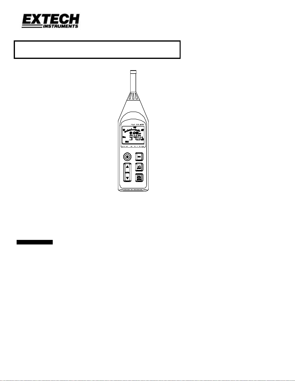
Model 407764
Datalogging Sound Level Meter
• Range: 30dB to 130dB
• 4-digit LCD Display with 0.1dB resolution
• A and C Frequency Weighting
• RS-232 PC Interface with
16,000 point datalogger and
Date / Time Stamp
• Auto-Ranging
1. INTRODUCTION
Congratulations on your purchase of Extech’s Sound Level Meter. This professional meter, with
proper care, will provide years of safe reliable service.
407764 Ver. 1.1 October 2000

2
2. SPECIFICATIONS
Applicable Standards IEC651 Type 2, ANSI S1. 4 Type 2
Accuracy ±1.5dB (under reference conditions)
Frequency range 31.5Hz - 8KHz
Measuring level 30 - 130dB
Frequency weighting A and C
Microphone 0.5” Electret condenser microphone
Display 4-digit LCD
Resolution: 0.1dB
Display period: 0.5 sec.
Bargraph 50dB scale (1dB steps). Display period: 50mS; Auto-ranging:
Sampling rate 50mS
Time weighting FAST: 125mS, SLOW: 1 sec.
MAX Maximum reading held
Level ranges 30-80dB, 40-90dB, 50-100dB, 60-110 dB, 70-120dB, 80-130dB
Auto range 30 to 130dB
Linearity range 50dB
Alarm function OVER indicator for readings higher than high limit.
UNDER indicator for readings lower than low limit.
AC output 0.707 Vrms at Full Scale
Output impedance approx. 600Ω
DC output 10mV / dB
Output impedance approx. 100Ω
Power supply Four 1.5V ‘AA’ batteries
Battery life Approx. 30 hrs continuous operation
AC adapter Voltage: 6VDC
Voltage Ripple: < 100mVpp
Supply Current: > 100mADC
Socket: Pin Ground
Casing: Positive
External Diameter: 3.5mm
Operating temperature 32 to 104oF (0 to 40oC)
Operating humidity 10 to 80%RH
Storage temperature 14 to 140oF (-10 to 60oC)
Storage humidity 10 to 80%RH
Memory size 16,000 data records with Date and Time Stamping
RS-232 Interface Baud rate: 9600bps
Dimensions 10.4 x 2.8 x 1.4” (265 × 72 × 35mm
Weight Approx. 11.5 oz. (358g) including battery
Accessories Batteries, carrying case, screwdriver , windscreen, 3.5mm plug, RS-232
100dB scale, 2dB steps
(Total of 6 ranges)
cable , 9- to 25-pin gender charger, WindowsTM Software.
407764 Ver. 1.1 October 2000
3
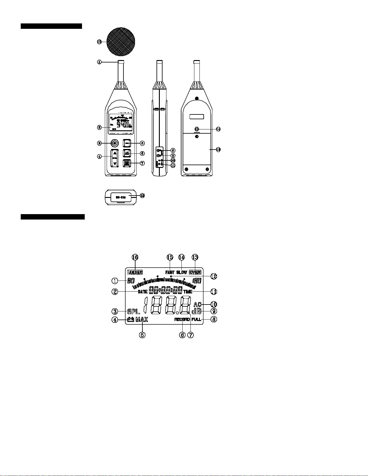
3. METER DESCRIPTION
1. Microphone
2. Display
3. Power Switch
4. Level range control switch
5. MAX hold switch
6. Frequency Weighting switch
7. Response Time select switch
8. AC output terminal
9. DC output terminal
10. CAL (Calibration) pot.
11. External DC 6V power
12. RS-232 Interface Connector
13. Battery Cover
14. Tripod mounting screw
15. Windscreen
(Figure 1)
4. DISPLAY DESCRIPTION
1. Range selection
2. Date information
3. SPL: Instantaneous sound pressure level
4. Low -Battery
5. MAX: Maximum SPL value is held
6. Data recording
7. Measurement value
8. Memory full
9. Units
10. Frequency weighting (A/C)
11. TIME function
12. 50dB level (Bargraph)
13. Over range
14. SLOW time response
15. FAST time response
16. Under range
(Figure 2)
407764 Ver. 1.1 October 2000
4
5. SAFETY AND MEASUREMENT PREPARATION
• Read the following safety information before attempting to operate the meter
• Use the meter only as specified or the meter's built-in protection may be impaired.
Maintenance & Cleaning
• Service not covered in this manual should be performed by qualified personnel
• Periodically wipe the case with a dry cloth. Do not use abrasives or solvents.
Safety symbols
Meter is protected throughout by double insulation or
reinforced insulation.
When servicing, use only specified replacement parts.
CE
Battery Loading
Remove the battery cover on the rear of the instrument and install four 1.5V AA batteries
Battery Replacement
When the battery voltage drops to a critical level, the appears on the LCD. Replace
batteries as soon as possible after the battery symbol appears.
6. MEASUREMENTS
1. Power the meter and select the desired Response Time (Fast or Slow) and
Frequency Weighting (A or C). If the sound source consists of short bursts or the
application calls for capturing only sound peaks, set response to FAST. To measure
average sound level, use the SLOW setting. Select A-weighting for averaged,
flat-response sound level readings or C-weighting for human ear response
simulation where the tests are conducted for personnel safety analysis.
2. Select the desired range manually or enable the Autorange function (Range:
30-130dB).
3. Hold the instrument comfortably in hand or position on tripod. Point the microphone
toward the noise source, the sound pressure level will be displayed on the meter’s
LCD display.
4. When MAX (maximum hold) mode is selected by pressing the MAX key, the
instrument captures and holds the maximum noise level reading on the display.
Press the MAX key again to clear the MAX reading.
5. Turn OFF the instrument and remove battery when not in use.
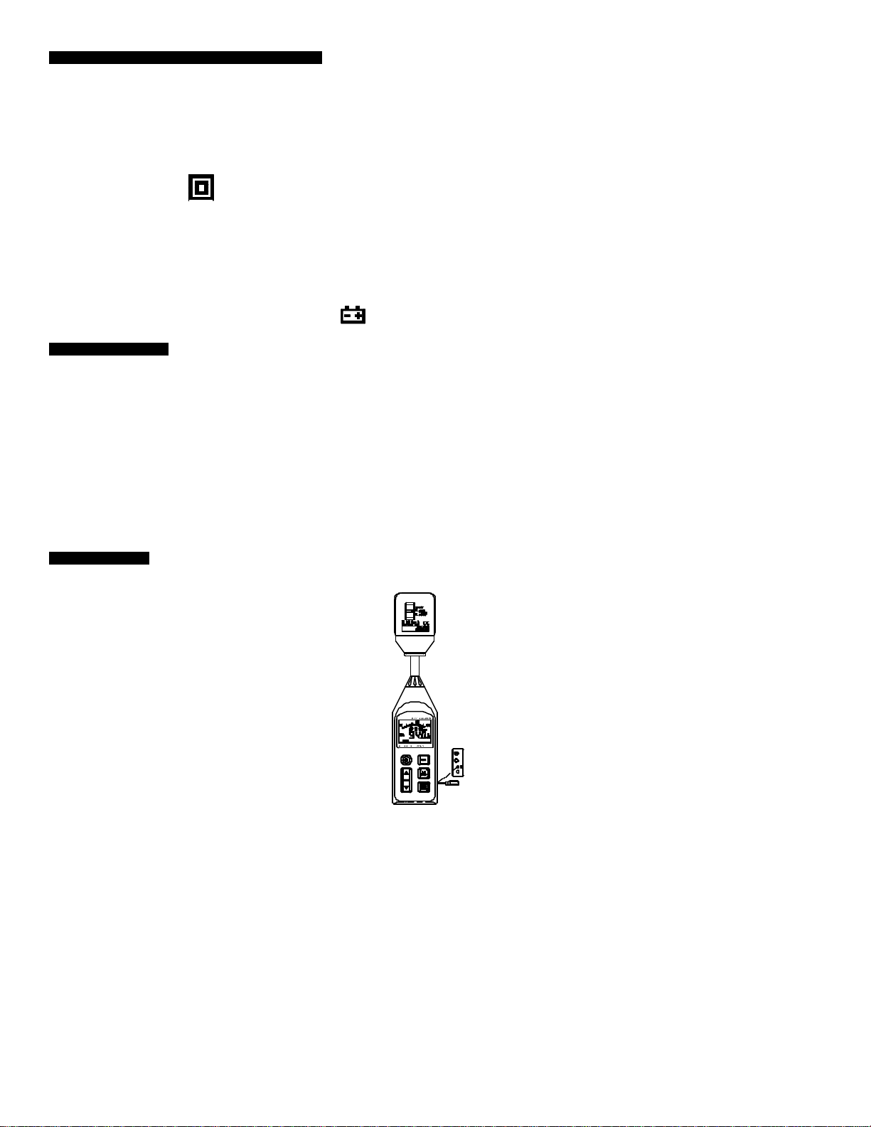
7. CALIBRATION
Note that a Sound Level Calibrator is required. Set up the meter as listed in Step 1 below.
Follow the remaining steps to Calibrate the meter.
1. Display: SPL (dBA)
Response Time: FAST
Disable the MAX function
Range: 70 to 120dB.
2. Insert the microphone carefully into the sound level
calibrator.
3. Power the calibrator and adjust the Sound Level
Meter’s CAL potentiometer (as shown in figure at
right) to match the Calibrator’s output.
4. Typically a Sound Level Calibrator will supply 94dB
at 1KHz. Adjust the Sound Level Meter’s CAL
potentiometer for a 94dB LCD display.
(Figure-3)
Complies with EMC
407764 Ver. 1.1 October 2000

5
8. DATALOGGING
TIP (AC)
RING (DC)
Sleeve (GND)
(Figure 5)
1. To record data, press & hold the RECORD key for 3 seconds until the “RECORD” symbol
flashes once per second on the LCD. Press the Record key again to stop recording data.
2. If the recording memory is full, the “FULL” symbol will appear on the LCD.
3. To Clear the recording memory press and hold the RESET key and power the meter. The
LCD will show the “dEL” icon letting the user know that the datalog memory has been
cleared.
4. To Dump or Record data via a PC refer to the PC Interface section below.
9. ANALOG OUTPUT
The 407764 has an AC/DC analog output jack located on the right side. The meter transmits
10mvDC / dB (for AC the full scale value is 0.707VAC). The output impedance is 600Ω for AC
and 100Ω for DC. Use the supplied 3.5mm stereo mini-plug (tip-ring-sleeve) (schematic is
shown below). The output can be connected to a chart recorder, datalogger, or other data
storage device.
(Figure 4)
10. PC INTERFACE
10.1 Connecting the Meter to a PC
Refer to Figure 5. Connect the 9-pin
male connector to the Sound Level
Meter, and connect the 9-pin female
connector to the 9-pin COM1 PC port. If
COM1 is used by the mouse, connect
the 25-pin female connector to the
25-pin COM2 PC port (you’ll need to use
the included 9- to 25-pin adapter).
10.2 PC Requirements
— 486 IBM compatible PC or better
— One 3.5" high density disk drive
— Two serial ports (one for mouse, one for Meter).
— 4M Bytes H.D. storage space
— EGA or VGA monitor
— Windows 95/98 Operating System
— 3-button or 2-button Microsoft compatible mouse. At least a 486 PC is recommended
for displaying all software windows with a fast sampling rate (such as 1 second). If a
386/25 PC is used, you can only open one window (LIST, GRAPH, ANALOG) at a time
when using fast sampling rates.
10.3 Installing the Windows Application Program
407764 Ver. 1.1 October 2000
a). Start Microsoft Windows
b). Close all applications
c). Insert Program disk to the floppy drive
d). From the START menu select Run
e). Type a:\setup and press the Enter key.
6
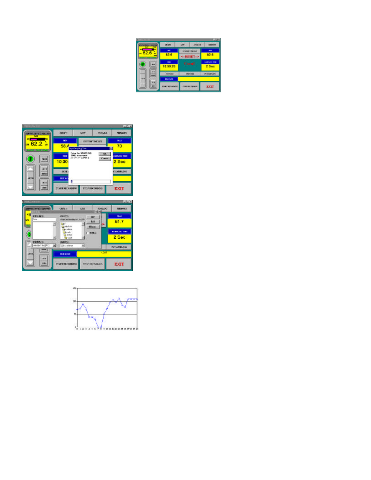
10.4 Software Displays Figures 6 through 15
TIME: Real Time Clock Setting
PC SAMPLING: Datalog Sampling Rate
MIN: The minimum value recorded.
RESET: Clear min and max stored readings
MAX: The maximum value recorded
SYS. TIME SET: Set the Real Time Clock
SAVE AS: Click here to Save the file
OPEN FILE: Open a data file (*.dat)
FILE NAME: When a file is open, the file name will display here
START RECORDING: After opening a file, click to start recording.
STOP RECORDING: Stop recording and close the file
— The Control Panel (Figure 6)
(Figure-7)
Selecting the datalog sample rate
(Figure-8)
Opening a datalog file (*.dat)
10.5 Menu functions
q Displays
Graph
(Figure-9)
407764 Ver. 1.1 October 2000

7
List
(Figure-10)
Commands:
Pause The listing of the data will halt until Continue is selected
Continue Resumes datalogging listing
Save Saves list data to file
Exit Exit current window
— Analog Display Simulation
10.6 DATA DOWNLOAD
q Memory
(Figure-11)
(Figure-12)
In the example for Figure 12, there are 3
sets of recorded data in memory. Set No.
3 has 246 records.
Note: If you want to change the ID
CODE or the SAMPLING Time, click
on the desired parameter and type the
changes.
Memory size: 16,000 readings max.
407764 Ver. 1.1 October 2000

8
To Download the contents of the meter
Step 1: Click the MEMORY icon on the Main software screen.
Step 2: click the NUMBERS OF SETS button, the number of sets will appear.
Step 3: Click on the TIME OF RECORDING button to view each recorded set.
Step 4: Click on the desired set. The number of records in the set will appear and the
Step 5: Click the SHOW DATA button for details on each record. Figure 13 shows the
(Figure-13) – List of data records
(Figure-14) – Graph of datalog records
data will be downloaded from meter to PC. Save to disk if desired.
data list. Select SAVE, PRINT, GRAPH, or EXIT from the menu choices.
(Figure-15) – Selecting a range of datalog records
407764 Ver. 1.1 October 2000

9
11. CALIBRATION / REPAIR SERVICES
Extech offers complete repair and calibration services for all of the products we sell. For
periodic calibration, NIST certification or repair of any Extech product, call customer service
for details on services available. Extech recommends that calibration be performed on an
annual basis to insure calibration integrity.
12. WARRANTY
EXTECH INSTRUMENTS CORPORATION warrants this instrument to be free of defects
in parts and workmanship for one year from date of shipment (a six month limited warranty
applies on sensors and cables). If it should become necessary to return the instrument for
service during or beyond the warranty period, contact the Customer Service Department
at (781) 890-7440 for authorization. A Return Authorization (RA) number must be issued
before any product is returned to Extech. The sender is responsible for shipping charges,
freight, insurance and proper packaging to prevent damage in transit.
This warranty does not apply to defects resulting from action of the user such as misuse,
improper wiring, operation outside of specification, improper maintenance or repair, or
unauthorized modification. Extech specifically disclaims any implied warranties or
merchantability or fitness for a specific purpose and will not be liable for any direct, indirect,
incidental or consequential damages. Extech's total liability is limited to repair or
replacement of the product.
The warranty set forth above is inclusive and no other warranty, whether written or oral, is
expressed or implied.
Copyright © 2000 Extech Instruments Corporation. All rights reserved
including the right of reproduction in whole or in part in any form.
APPENDIX - TYPICAL ‘A’ WEIGHTED SOUND LEVELS
dB
50HP Siren (100')
Jet takeoff (200')
Riveting machine
Subway (20')
Pneumatic drill (50')
Vacuum cleaner (10')
Large store
Small office
Night residential area
Whisper (5'0)
Threshold of hearing
140
130
120
110
100
90
80
Freight train (100')
70
60
50
40
30
20
10
0
Chain saw
Boiler room
Speech (1')
Large Office
Residence
Sound studio
407764 Ver. 1.1 October 2000
 Loading...