

Page 1
Instruction Manual
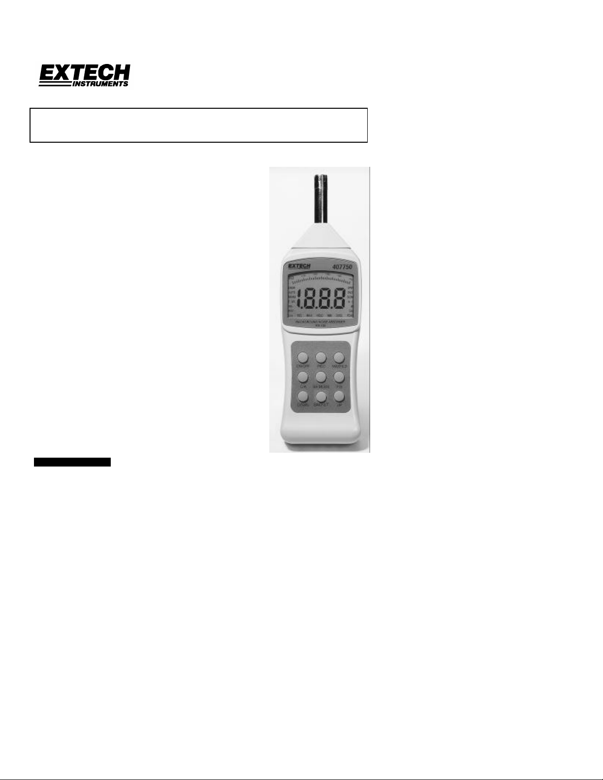
MODEL 407750
Digital Sound Level Meter
q Auto/Manual Ranging
q A/C weighting & Fast/Slow response
q Background noise absorption
q RS-232 PC Interface
q The frequency spectral curves of this high resolution
(0.1dB) meter meet ANSI and IEC-651 Type II standards
1. INTRODUCTION
Congratulations on your purchase of the Extech Model 407750 Digital Sound Level Meter.
This professional meter wilth proper care will provide years of safe reliable service.
1 407750 Ver. 1.03 6/99
Page 2
2. SPECIFICATIONS
Display Backlit Super Large 3-1/2 digit (1999 count) LCD
with 0.8” digits plus analog bargraph and
multifunction displays
Display update rate Main LCD: 0.5 seconds; Bargraph: 50mS
Analog Bargraph 1dB steps with 50dB display range
Microphone Electret condensor (6mm diameter)
Measurement
31.5Hz to 8KHz
Bandwidth
Measurement Range A weighting: 30 to 130dB; C weighting: 35 to 130dB
6 ranges in 10 dB steps: 30 to 80dB, 40 to 90dB, 50
to 100dB, 60 to 110dB, 70 to 120dB, 80 to 130dB
Accuracy / Resolution ± 1.5dB / 0.1dB
Time response
Fast/Slow
selections
Analog output 0.707Vac rms at full scale; 10mVdc/dB
Power 9V Battery (006P or 6F22)
Dimensions/weight 80x256x38mm / 240g
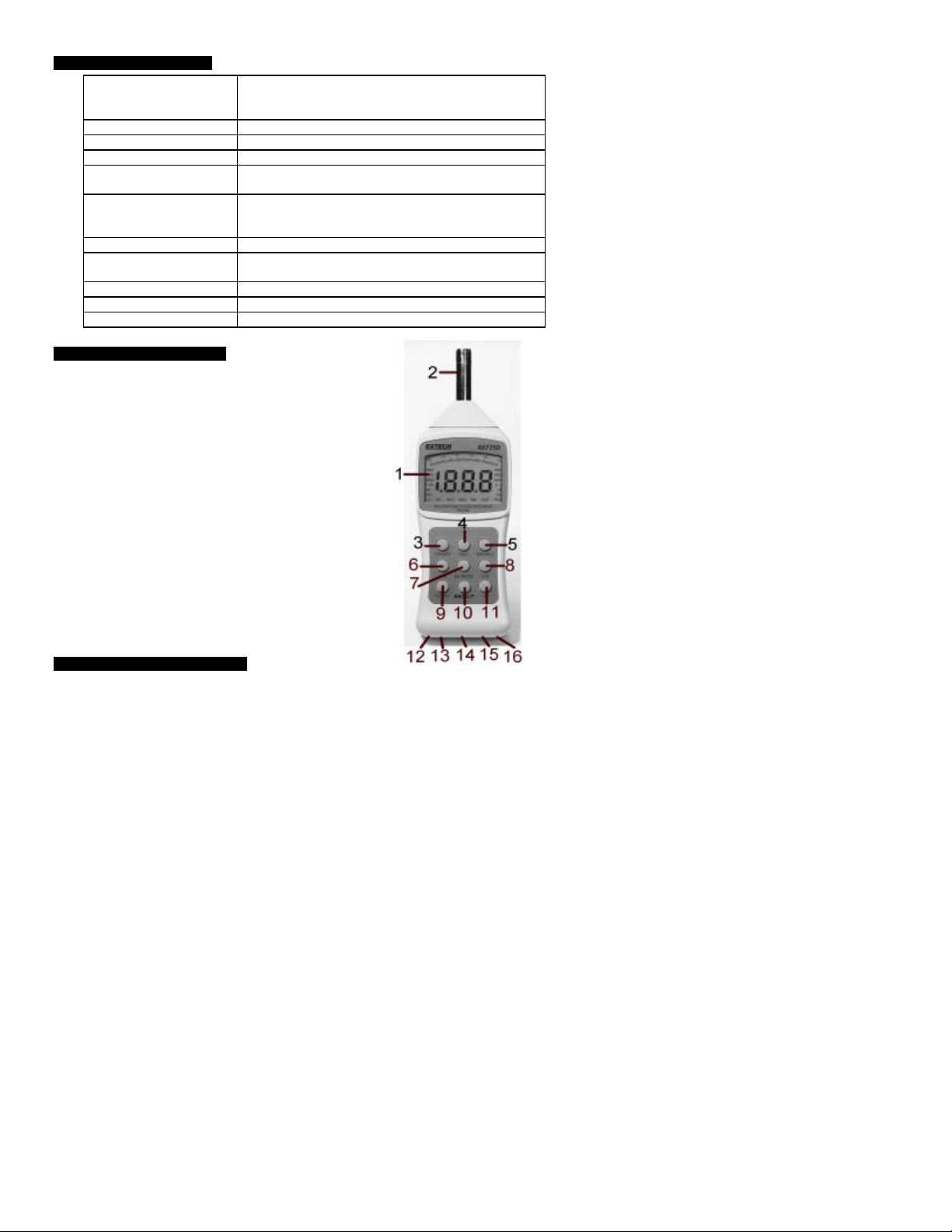
3. METER DESCRIPTION
1. LCD Display
2. Microphone
3. ON/OFF key
4. REC (Record) key
5. MAXHLD (Max Hold) key
6. C/A Weighting Select key
7. BA (Background Absorber) key
8. F/S Fast / Slow Response select key
9. DOWN
10. Backlit (LCD backlighting) key
11. UPPER
12. AC adaptor jack
13. Calibration screw adjust
14. AC analog output jack
15. DC analog output jack
16. RS-232 output jack
17. Battery Compartment (not pictured)
18. Threaded Tripod mount access (not pictured)
4. METER OPERATION
4.1 Quick Start
1. Power the meter by pressing the ON/OFF key. The meter’s LCD will count down
to zero (99.9, 88.8, 77.7 etc.) and then begin measuring sound levels. If the LCD
does not display after pressing the ON/KEY check the 9V battery (see section 5).
2. Place the meter on a tripod via the tripod mount on the rear of the meter or hold
the meter in hand to take noise measurements.
3. Point the microphone toward the source of the sound level to be measured and
view the reading on the meter’s LCD.
4.2 ‘A’ and ‘C’ Weighting. Select ‘A’ or ‘C’ Weighting via the C/A key. The LCD will reflect
which weighting mode is currently selected. Use ‘A’ weighting to have the meter
respond as the human ear would with regard to frequency response (the human ear
boosts and cuts amplitude over the frequency spectrum therefore it is not ‘flat’
responding). ‘A’ weighting is used for environmental measurements, OSHA regulatory
testing, law enforcement, and workplace design. Select ‘C’ weighting for flat response
2 407750 Ver. 1.03 6/99
Page 3

measurements (no amplitude boost or cut across the frequency spectrum). ‘C’
weighting is suitable for the sound level analysis of machines, engines, etc.
4.3 FAST/SLOW Response Time. Select either FAST or SLOW measurement response
mode via the F/S key. The LCD will reflect the currently selected mode. Selection of
Fast or Slow is determined by the application and any directives or standards related to
that application. For example, most hearing conservation or OSHA related testing is
done using SLOW and A weighting.
4.4 MAX HOLD. The meter is capable of taking continuous measurements and only
updating the LCD when a higher reading, than the one presently on the display, is
detected. The bargraph display continues to change while the main LCD waits for a
higher reading however. Press the MAXHLD key to activate the MAX HOLD mode. The
LCD will reflect the MAX HOLD function. Press the MAXHLD key again to return to
normal mode.
4.5 Record (REC) Function. To Record the Maximum and Minimum sound level
measurements over a programmable period of time, press the REC key. The REC
indicator will appear on the LCD. Once the REC key is pressed, the meter begins
keeping track of the highest (MAX) and lowest (MIN) readings. Press the REC again
and the MIN indicator will appear on the LCD next to the REC along with the lowest
sound level reading since the REC key was pressed. Press the REC again and the
MAX indicator will appear along with the highest reading the meter has encountered
since the REC key was first pressed. Press and hold the REC until the REC indicator
extinguishes to exit the RECORD mode.
4.6 BA (Background Noise Absorber) Mode. The Background Noise Absorber function
provides the capability to accurately measure equipment noise even in the presence of
a high background noise. The Sound Level Meter permits the user to initially store the
background noise level as a reference level and then run a machine or other device
measuring its sound level referenced to the stored background noise value. To operate
the meter in BA mode, follow these steps:
1. Power the meter.
2. Press the MAXHLD key and the MAX HOLD icon will appear on the LCD.
3. Press the BA key and an ‘F” will appear to left of the SPL display icon.
4. Press the MAX HOLD key again and the MAX HOLD icon will reappear on the
LCD.
5. The meter is now displaying the background, reference noise.
6. Power the device under test and note the new sound level meter reading.
7. If the reading changes, the new reading is the sound level of the device. If the
reading does not change, the noise produced from the device is either equal to or
less than the background noise.
8. Press the BA key again to return to the normal mode of operation.
4.7 Auto and Manual Ranging. The meter powers up in the Auto Range mode, meaning
that the display will automatically find the most correct range for a specific
measurement display in order to produce the best accuracy. However, if it is desired to
set the range manually, follow these steps:
1. Power the meter
2. Notice the two (2) digit number to the immediate left of the analog bargraph. This
number informs the user as to the low end of the presently selected range (see
the specifications for the range listings).
3. To change the range press the UP key to raise the range or press the DOWN key
to lower the range. The two digit number on the left of the bargraph will change
with each keypress.
4. An advantage of Manual mode is that it takes less time for the meter to take a
reading. In Auto Range mode the meter must first hunt for the correct range
before displaying a measurement. Auto Range is certainly more convenient but it
depends on the application at hand to determine which mode to use.
4.8 LCD Backlighting. Press the BACKLIT key to illuminate the LCD for a period of 5
seconds. This is handy in dimly lit or dark measurement areas. The automatic backlight
extinguishing preserves battery life.
3 407750 Ver. 1.03 6/99
Page 4

4.9 Auto Power Off
This meter includes an automatic power down feature which preserves battery life. If the
unit is not used for approximately 20 minutes, the meter shuts off automatically. To
override this function, follow these steps:
1. From a power OFF condition, press and hold the ON/OFF and MIN/MAX keys
simultaneously.
2. When ‘n’ appears on the display release first the MIN/MAX and then the ON/OFF
keys.
3. The Auto Power Off feature is now disabled. The Auto Power Off feature is reactivated the next time the meter is powered down.
4.10 Analog Outputs. The meter includes an AC and a DC analog retransmitted output
for use with chart recorders, dataloggers, etc. The AC output is 0.707V rms full scale
and the DC output is 10mV per dB. The 3.6mm output mini-plugs are located and
labeled on the bottom of the instrument.
4.11 RS-232 Output. The meter includes an RS-232 PC interface jack. The interface
permits the capture of sound level data on a PC. The cable and software for data
acquisition can be purchased separately and includes instructions.
5. BATTERY REPLACEMENT
When the low battery message appears on the LCD, the 9V battery has fallen to a
critically low voltage level and should be replaced as soon as possible. The battery
compartment cover resides at the rear of the meter. Remove the rear battery compartment
screw and remove the battery compartment cover, change the battery, and replace the
compartment cover.
6. CALIBRATION
The meter includes a Calibration Screw Adjustment labeled on the bottom of the meter. A
calibrator device that fits over the microphone must be used. Extech can supply these.
Once the Calibrator is affixed on the microphone, adjust the calibration screw for the
proper reading.
7. REPAIR AND CALIBRATION SERVICES
Extech offers complete repair and calibration services for all of the products we sell. For
periodic calibration, NIST certification or repair of any Extech product, call customer
service for details on services available. Extech recommends that calibration be performed
on an annual basis to insure calibration integrity.
8. WARRANTY
EXTECH INSTRUMENTS CORPORATION warrants the basic instrument to be free of
defects in parts and workmanship for one year from date of shipment (a six month limited
warranty applies on sensors and cables). If it should become necessary to return the
instrument for service during or beyond the warranty period, contact the Customer Service
Department at (781) 890-7440 for authorization. A Return Authorization (RA) number
must be issued before any product is returned to Extech. The sender is responsible
for shipping charges, freight, insurance and proper packaging to prevent damage in
transit. This warranty does not apply to defects resulting from action of the user such as
misuse, improper wiring, operation outside of specification, improper maintenance or
repair, or unauthorized modification. Extech specifically disclaims any implied warranties
or merchantability or fitness for a specific purpose and will not be liable for any direct,
indirect, incidental or consequential damages. Extech's total liability is limited to repair or
replacement of the product. The warranty set forth above is inclusive and no other
warranty, whether written or oral, is expressed or implied.
4 407750 Ver. 1.03 6/99
 Loading...