

Page 1
INSTRUCTION MANUAL
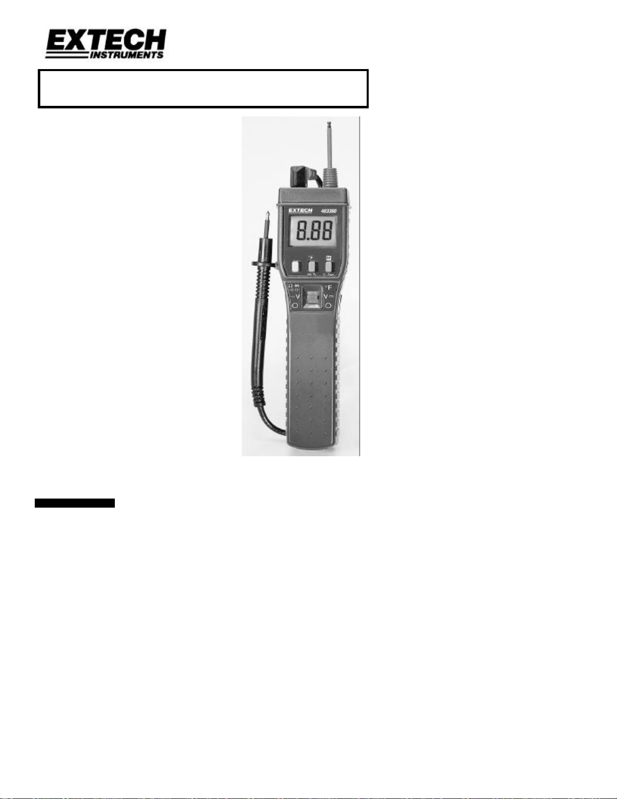
Model 403380
Autoranging DMM ProbeMeterTM
• Measures voltage, resistance, frequency,
capacitance, temperature, and duty cycle.
• Back lit LCD with Autorange and full function
displays
• Audible continuity and diode tests
1. INTRODUCTION
Congratulations on your purchase of Extech’s Autoranging DMM ProbemeterTM. This
professional meter, with proper care, will provide years of safe reliable service.
1 403380 Ver. 1.01 7/99
Page 2
2. SPECIFICATIONS
2.1 General Specifications
Display 2500 count backlit LCD
Polarity Automatic, positive implied, negative polarity indication
Overrange "OL" or "-OL" is displayed
Low battery indication The low battery icon is displayed when the battery voltage
drops below the operating level
Measurement rate 2.5 times per second, nominal
Operating conditions 32 oF to 104oF (0 to 40oC) at <70% relative humidity
Storage Temperature -4oF to 140oF (-20 to 60oC), 0 to 80% R.H.
Accuracy Stated accuracy at 73.4oF ±9oF, <75% relative humidity
Auto Power off After 30 minute period of non-use
Safety EN61010-1 protection class II over-voltage category
(CAT II 600V) pollution degree 2
Power 4 x 1.5V (AAA size) batteries
Battery life 500 hours typical with alkaline
Dimensions 6.7 (H) x 1.7 (W) x 1.6 (D)” (170mm x 44mm x 40mm)
Weight 4.5 oz. (140g) including batteries.
2.2 Function Specifications
Function Range Resolution Accuracy
DC Volts
Input impedance: 10MΩ
Overload protection:
600VAC/DC
AC Volts (50-500Hz)
Input impedance: 10MΩ
Overload protection:
600VAC/DC
Resistance
Open ckt. V: 0.4VDC
Overload protection:
500VAC/DC
Capacitance
(Autoranging)
Overload protection:
250mV 100uV ±(0.25% rdg + 5dgts)
2.5V 1mV
±(0.25% rdg + 1dgt)
25V 10mV
250V 0.1V
600V 1V
250mV 100uV not specified
2.5V 1mV
±(0.75% of rdg + 4dgts)
250V 0.1V
600V 1V
250Ω 0.1Ω
2.5kΩ 1Ω
±(0.3% rdg + 3dgts)
±(0.3% rdg + 1dgts)
25kΩ 10Ω
250kΩ 0.1kΩ
2.5MΩ 1kΩ
25MΩ 10kΩ
250nF 0.1nF
±(3.5% rdg + 4 dgts)
±(5.0% rdg + 10dgts)
2.5uF 1nF
25uF 10nF
500VAC/DC
Frequency
(Autoranging)
Sensitivity: 1.0V min.
Overload protection:
500VAC/DC
(Type K thermocouple)
Duty Cycle (2Hz-1kHz)
Overload protection:
5Hz 0.001Hz
±(0.05% rdg + 2dgts).
50Hz 0.01Hz
500Hz 0.1Hz
5kHz 1Hz
-4oF to
2498oF
0.1oF/1oF
±(2.0% rdg + 6oF) –4oF to 923oF Temperature
±(3.0% rdg + 4oF) 923oF to 2498oF
10%-90% 0.1% ±5dgts@2Vrms min
Pulse Width : 50uSec
500VAC/DC
Continuity
Audible alert <100Ω; Overload protection: 500VDC/AC
Diode Accuracy: ±(3.0% rdg + 3dgts); Resolution: 1mV.
Test current: 0.25A ±0.2mA; Test voltage: <1.6V.
2 403380 Ver. 1.01 7/99
Page 3
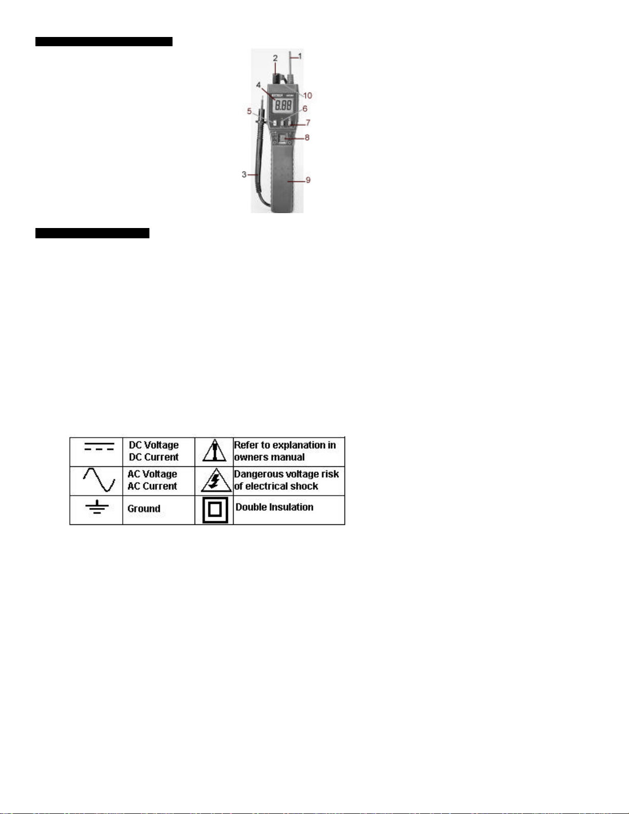
3. FRONT PANEL DESCRIPTION
1 Positive test lead (in meter jack)
2 Negative test lead (in meter jack)
3 Negative test lead (test end)
4 LCD Display
5 Select key
6 Temperature, duty cycle, Hz key
7 Data Hold / Backlight key
8 Function switch
9 Handle
10 Thermocouple input socket (top)
4. SAFETY INFORMATION
The following safety information must be observed to insure maximum personal safety
during the operation of this meter:
1. Do not use the meter if the meter/test leads appear damaged or if you suspect that the
meter is not operating properly.
2. This meter is not recommended for high voltage industrial use; for example, not for
measurements of 440 VAC or 600 VAC industrial power mains. The unit is intended
for use with low energy circuits to 600V AC/DC or high energy circuit to 250VAC or DC.
3. Use caution when working > 60V dc / 30V ac rms. Such voltages pose a shock hazard.
4. When using the probes, keep your fingers behind the finger guards on the probes.
5. Measuring voltage which exceeds the limits of the meter may cause damage and
expose the operator to a shock hazard. Always respect the voltage limits as stated on
the meter.
6. If the equipment is used in a manner not specified by the manufacturer, the protection
provided by the instrument may be impaired.
7. Refer to the following International Safety Symbols
3 403380 Ver. 1.01 7/99
Page 4

5. PREPARATION FOR MEASUREMENT
Before attempting measurements, read the Safety Information in Section 4. Always
examine the instrument for damage, contamination (excessive dirt, grease, etc.) and
defects. Examine the test leads for cracked or frayed insulation. If any abnormal
conditions exist do not attempt any measurements.
5.1 Auto Power-OFF mode
If unused for about 30 minutes, the meter will power down automatically. To disable
Auto Power-OFF mode, press the SELECT key while powering the meter.
5.2 Backlight / Data-Hold key
Press this key briefly to activate the Data Hold mode. The "H" annunciator will appear on
the LCD and the measurement data will freeze. Press and hold this key for 2 seconds to
turn the LCD backlighting on. Briefly press the key to return to normal display. To turn
the Backlight off press and hold again for 2 seconds.
5.3 Function Switch
Lower position (O) is power off mode, center position is voltage mode, and top position
is diode, continuity, capacitance, temperature, and resistance mode.
5.4 SELECT key
Press the yellow SELECT key to choose AC or DC volts when the voltage mode is
selected via the FUNCTION key. Press the SELECT key to choose the desired
measurement function when the FUNCTION switch is set to the
diode/continuity/ohms/capacitance mode. For reference, observe the display icons as
each mode is selected.
5.5 Hz, oF, % key
When the Function switch is in the upper position
(diode/continuity/ohms/capacitance/temperature modes), the Hz (frequency), oF
(Temperature), % (Duty Cycle) key permits the user to select the temperature function. If
the FUNCTION switch is set to the voltage position, the Hz/oF/% key permits the
selection of Frequency, Duty Cycle, or Voltage. Observe the LCD function icons to be
sure of which function is currently selected.
4 403380 Ver. 1.01 7/99
Page 5

6. OPERATION
6.1 Voltage Measurements
1. Connect the red test lead to the "V" jack and the black test lead to the "COM" jack.
2. Set the FUNCTION switch to voltage and press the yellow Select key to choose AC
or DC (the AC icon will appear on the LCD, the DC mode is implied).
3. Connect the test leads to the device or circuit being measured.
4. For dc, a (-) sign is displayed for negative polarity; positive polarity is implied.
6.2 Frequency Measurements
1. Set the FUNCTION switch to voltage and press the Hz/%/oF key to scroll through
the voltage/frequency/duty cycle modes. Select Frequency (Hz will appear on the
LCD).
2. Connect the red test lead to the "V" jack and the black test lead to the "COM" jack.
3. Connect the test leads to the point of measurement and read the LCD.
6.3 Duty Cycle Measurements
1. Set the FUNCTION switch to voltage and press the Hz/%/oF key to scroll through
the voltage/frequency/duty cycle modes. The % mode represents duty cycle.
2. Connect the red test lead to the "V " jack and the black test lead to the "COM" jack.
3. Connect the test leads to the point of measurement. The display will indicate 0.1%
to 99.9% duty cycle.
6.4 Resistance Measurements
1. Set the FUNCTION switch to the Ω position.
2. Remove power from the equipment under test.
3. Connect the red test lead to the "V" jack and the black test lead to the "COM" jack.
4. Touch the probes to the test points and read the resistance display.
6.5 Diode Tests
1. Set the FUNCTION switch to the diode position.
2. Remove power from the equipment under test.
3. To scroll through the continuity/diode/capacitance/resistance modes, press the
yellow SELECT key. Select diode by observing the diode symbol on the LCD while
scrolling.
4. Touch probes to the diode (Red lead to Anode, Black lead to Cathode of diode). A
correct forward-voltage drop is about 0.6V (silicon diode) or 0.3V (germanium).
5. Reverse the probes. If the diode is good, "OL" will display. If the diode is shorted,
".000" or another small number will display. If the diode is open, "OL" is displayed,
in both directions.
6. If a diode’s junction is measured in circuit and a low reading is obtained, the
junction may be shunted by a resistance of less than 1k. In this case the diode
must be disconnected from the circuit for accurate testing.
6.6 Continuity Measurements
1. Set the FUNCTION switch to the continuity position (same position as diode).
2. Remove power from the equipment under test.
3. To scroll through the continuity/diode/capacitance/resistance modes, press the
SELECT key.
4. Connect the test leads to the two points for which continuity is to be tested. The
audible tone will sound if the resistance is less than approximately 100 Ω.
5 403380 Ver. 1.01 7/99
Page 6

6.7 Capacitance Measurements
1. Set the FUNCTION switch to the capacitance position.
2. Remove power from the equipment under test.
3. To scroll through continuity/diode/capacitance/resistance modes, press the SELECT
key.
4. Discharge capacitors before trying to measure them.
5. Connect the "+" lead to the "V" jack and the "-" lead to the "COM" jack.
6. Touch the test leads to the capacitor, observing polarity of electrolytic capacitors,
and read the capacitance value on the LCD.
6.8 Temperature Measurements
1. Set the FUNCTION switch to the "oF" position and press the "oF” key to toggle the
ohms/oF modes.
2. Connect a Type-K thermocouple to the jack on the instrument. Place the probe or
thermocouple tip on or in the material to be measured and read the temperature on
the display.
6 403380 Ver. 1.01 7/99
Page 7

7. MAINTENANCE
7.1 Battery Replacement
Power is supplied by four 1.5V (AAA size) batteries. The low battery icon (symbol of a
battery on lower left corner of LCD) appears on the LCD display when replacement is
necessary. To replace the batteries, remove the rear screw and open the battery
compartment with your thumb. Remove and replace with fresh batteries. Reinstall
battery compartment cover.
7.2 Cleaning
Periodically wipe the case with a damp cloth and detergent, do not use abrasives or
solvents.
8. CALIBRATION / REPAIR SERVICES
Extech offers complete repair and calibration services for all of the products we sell. For
periodic calibration, NIST certification or repair of any Extech product, call customer
service for details on services available. Extech recommends that calibration be performed
on an annual basis to insure calibration integrity.
9. WARRANTY
EXTECH INSTRUMENTS CORPORATION warrants this instrument to be free of defects in parts and
workmanship for one year from date of shipment (a six month limited warranty applies on sensors and
cables). If it should become necessary to return the instrument for service during or beyond the warranty
period, contact the Customer Service Department at (781) 890-7440 for authorization. A Return
Authorization (RA) number must be issued before any product is returned to Extech. The sender is
responsible for shipping charges, freight, insurance and proper packaging to prevent damage in transit.
This warranty does not apply to defects resulting from action of the user such as misuse, improper wiring,
operation outside of specification, improper maintenance or repair, or unauthorized modification. Extech
specifically disclaims any implied warranties or merchantability or fitness for a specific purpose and will not
be liable for any direct, indirect, incidental or consequential damages. Extech's total liability is limited to
repair or replacement of the product. The warranty set forth above is inclusive and no other warranty,
whether written or oral, is expressed or implied.
7 403380 Ver. 1.01 7/99
 Loading...