

Page 1
User's Guide
Datalogging Light Meter
with PC Interface
Model 401036
Page 2
Warranty
EXTECH INSTRUMENTS CORPORATION warrants this instrument to be free of defects
in parts and workmanship for one year from date of shipment (a six month limited warranty
applies to sensors and cables). If it should become necessary to return the instrument for
service during or beyond the warranty period, contact the Customer Service Department at
(781) 890-7440 ext. 210 for authorization or visit our website www.extech.com for contact
information. A Return Authorization (RA) number must be issued before any product is
returned to Extech. The sender is responsible for shipping charges, freight, insurance and
proper packaging to prevent damage in transit. This warranty does not apply to defects
resulting from action of the user such as misuse, improper wiring, operation outside of
specification, improper maintenance or repair, or unauthorized modification. Extech
specifically disclaims any implied warranties or merchantability or fitness for a specific
purpose and will not be liable for any direct, indirect, incidental or consequential damages.
Extech's total liability is limited to repair or replacement of the product. The warranty set
forth above is inclusive and no other warranty, whether written or oral, is expressed or
implied.
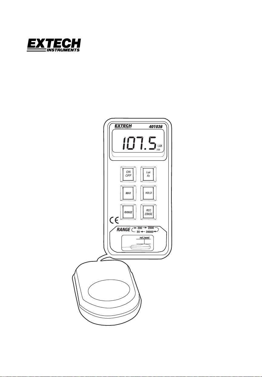
Introduction
Congratulations on your purchase of the Extech 401036 Datalogging Light Meter. This
device measures light intensity to 20,000 Foot-candles (Fc) or Lux. 16,000 measurement
readings can be logged by the meter and later transferred to PC using the RS-232
interface. Real-time meter/PC logging is also supported. Careful use of this meter will
provide years of reliable service.
Specifications
Display 3 ½ digit (2000 count) multifunction LCD display
Sensor
Ranges / Resolution 19.99, 199.9, 1999, and 1999 x 10 Fc and Lux
Accuracy ± (3% reading + 5 digits)
Repeatability ± 2%
Datalogger memory 16,000 readings max.
PC Interface RS-232C Serial Communications at 9600 bps
Range status indication 'OL' is displayed for measurement exceeding published limits
Sampling time 2.5 readings per second
Power Supply 9V battery (display includes low battery indicator);
Operating temperature 32 to 104oF (0 to 40oC)
Operating Humidity < 80% RH
Weight 9.6 oz. (300g)
Dimensions Meter: 5.7 x 2.8 x 1.5" (146 x 70 x 39mm);
Accessories Carrying case, WindowsTM software, PC Interface cable, &
Silicon Photo-diode meets C.I.E. photopic curve V (
50 hour typical battery life
Probe: 3.4 x 2.4 x 1.1" (87.5 x 60 x 29mm)
9V battery
λ)
Model 401036 Version 3.1 9/07 2
Page 3

Meter Description
1. 2000 Count LCD includes LUX, Fc, low battery, MAX, H (hold), & x10 indicators
2. ON/OFF key
3. Max. Hold key
displays only the maximum reading
4. Lux/Fc key
unit of measure. The LCD shows the
unit
5. Light Sensor
Collects light. Note that a tripod mount
is located on the rear of the sensor
6. Range key
desired range: 20, 200, 2,000, 20,000
7. Data Hold key
displayed measurement
8. Record/Erase key
store one reading; Press and hold for 3
seconds to activate the continuous
recording mode. Press again to end
recording
9. RS-232 jack
connection cable
10. Zero adjust
supplied lens cap and adjust the zero
pot for a 0.0 Fc/LUX display
Note that the battery compartment, tilt stand, and hanging mount are located on the rear of
the meter
Turns the meter on or off
When pressed, the LCD
Press to toggle the displayed
(Lens cover not shown)
Press repeatedly to select
Press to freeze the
Press momentarily to
Stereo jack for PC to Meter
Cover the sensor with
1
2
3
4
6
7
8
9
10
5
Spectral Sensitivity Curve
= Light Meter
= V (
Relative
Sensitivity (%)
Wavelength (nm)
100
80
60
40
20
400 450 500 550 600 650 700
Model 401036 Version 3.1 9/07 3
λ)
Page 4

Operation
1. Turn the meter ON or OFF with the ON/OFF key.
2. Press the Lux/Fc key to select the unit of measure for light intensity.
3. With the lens cap completely covering the light sensor, zero the meter by adjusting the
screw on the right side of the meter for an LCD reading of 0.0.
4. Remove the lens cap to allow the sensor to collect light.
5. Read the light intensity measurement on the LCD.
6. For over-range conditions, the ‘OL’ icon will display. Select a higher range by pressing
the Range key until a valid reading replaces the ‘OL’ display.
7. For the 20,000 range, multiply the displayed reading by a factor of 10.
Data Hold
Press the HOLD key to freeze the displayed reading. Press HOLD again to return to the
normal operating mode.
Maximum (MAX) reading
Press the MAX key to display only the highest reading. As higher measurements are made
the display updates accordingly. The ‘MAX’ icon appears on the LCD in this mode of
operation. To return to normal operation, press the MAX key again and the MAX indicator
will extinguish.
Range selection
Press the RANGE key to select the appropriate measurement range. Start with the lowest
range (20) and work up to higher ranges as needed. If ‘OL’ (overload) is displayed, press
the range key until a valid reading is displayed.
Datalogger
REC/ERASE Key
The REC/ERASE key is used to record and erase data. Press the REC/ERASE key once
to log one reading (REC icon flashes once on the LCD). To automatically datalog readings
at programmable intervals (continuous recording mode), press and hold the REC/ERASE
key for 3 seconds (REC icon begins flashing repeatedly).
Press the REC/ERASE key any time while recording to exit the record mode. When the
memory is full (16,000 readings or 255 sets), the LCD will display ‘FULL’ and recording
ends. To download and view the stored data, connect the meter to a PC and perform the
steps provided in the ‘PC Interface’ section of this manual.
To erase stored data, perform these steps:
1. With the meter turned off, press and hold the REC/ERASE key.
2. Turn the meter on by pressing the ON/OFF key and then immediately release the
ON/OFF key.
3. Continue to hold the REC/ERASE key until ‘del’ flashes 3 times on the LCD. The meter
automatically returns to normal operation after the data are erased.
Model 401036 Version 3.1 9/07 4
Page 5

Sampling Rate
The sampling rate is the interval of time between logged readings. Note that there are two
sampling rate selections for two separate datalogging scenarios described below:
1. PC Sampling Rate
The PC sampling rate is the rate at which measurements are recorded by the PC
while the meter is connected to the PC. This is known as real-time recording since
the readings are being taken by the meter and recorded by the PC at the same
time. Set the rate in the supplied software program as described in the PC
SAMPLING paragraph on page 6.
2. Datalogger Sampling Rate
This is the meter’s internal sampling rate used when the meter is logging readings
remotely in continuous recording mode (disconnected from the PC). The default
rate is 1 second. Change the rate in software by following the steps on page 6 for
SAMPLING TIME with the meter connected to the PC.
PC Interface
Connect the supplied interface cable to the phono jack on the right side of the light meter
and to the PC 9-pin COM port.
TM
Windows
Refer to separate instructions supplied on the Software Program disk for the operation of
the Windows
Software
TM
Software.
Model 401036 Version 3.1 9/07 5
Page 6

Battery Replacement
The meter uses a 9V battery for its operational power and it has a 50 hour typical life span.
Replace the battery when the low battery icon appears on the meter’s LCD display.
1. Remove the three (3) Phillips screws on the rear of the meter.
2. Open the meter housing and replace the battery
3. Close the meter housing and secure the rear screws
Calibration and Repair Services
Extech offers repair and calibration services for the products we sell. Extech also
provides NIST certification for most products. Call the Customer Service Department for
information on calibration services available for this product. Extech recommends that
annual calibrations be performed to verify meter performance and accuracy.
All rights reserved including the right of reproduction in whole or in part in any form.
Technical support: Extension 200; E-mail: support@extech.com
Repair & Returns: Extension 210; E-mail: repair@extech.com
Product specifications subject to change without notice
For the latest version of this User’s Guide, Software updates, and other
up-to-the-minute product information, visit our website: www.extech.com
Extech Instruments Corporation, 285 Bear Hill Rd., Waltham, MA 02451
Copyright © 2005 Extech Instruments Corporation
Support line (781) 890-7440
Model 401036 Version 3.1 9/07 6
 Loading...