

Page 1
User Guide
Digital AC/DC Clamp Meter
Model 38394
Page 2
Introduction
Congratulations on your purchase of Extech’s 38394 AC/DC Clamp Meter. This clamp
meter measures AC/DC Current to 600A, DC/AC Voltage, Resistance, Frequency,
Diode, and Continuity. This meter is shipped fully tested and calibrated and, with proper
use, will provide years of reliable service.
Safety
Safety Symbols
This symbol, adjacent to another symbol or terminal, indicates the user must
refer to the manual for further information.
This symbol, adjacent to a terminal, indicates that, under normal use, hazardous
voltages may be present
Double insulation
WARNING: This indicates that a potentially hazardous condition which, if not avoided,
CAUTION: This indicates that a potentially hazardous condition which, if not avoided,
Safety Precautions
WARNING: Improper use of this meter can cause damage, shock, injury or death. Read and
1. Always remove the test leads before making current measurements
2. Always remove the test leads before replacing the batteries
3. Inspect the condition of the clamp jaw, test leads and the meter for any damage
4. Do not exceed the maximum rated input limits
5. Use great care when making measurements, especially when the voltages are
6. Always discharge capacitors and remove power from the DUT (device under test)
7. Remove the batteries from the meter if the meter is to be stored for long periods
8. Ensure that the selected meter function matches the measurement to be taken
9. If the measured current is higher than the range selected for long periods,
10. To avoid discharge risks and erroneous readings, do not measure current on high
could result in death or serious injury.
could result in injury or damage to the meter.
understand this User Guide before operating the meter.
before operating the meter. Repair any damage or replace meter before use
greater than 25VAC rms or 35VDC. These voltages are considered a shock hazard
before performing Resistance or Continuity tests
overheating may occur compromising the safety and the operation of the meter’s
internal circuits
voltage conductors (>600V)
2
Model 38394 Version 3.0 11/07
Page 3
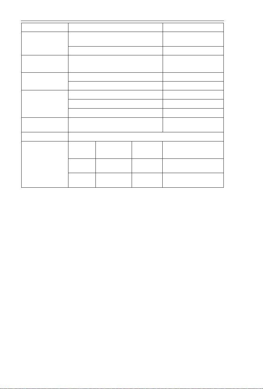
Specifications
Function Range Accuracy
AC/DC Current
AC Voltage 4.000V, 40.00V, 400.0V, 600.0V ±(1.2% rdg + 5d)
Resistance
Frequency (≥ 5V)
Continuity
Input Limits
Conductor Size 1.18" (30mm) maximum
Battery type Two (2) 1.5V AA batteries
Range Selection Automatic ranging
Display 5000 Count LCD
Overload Indication "1" or “-1”
Low Battery Indication Battery icon
Environmental conditions Installation Category III (clamp); Category II (DMM),
Operating Temperature/Humidity 32º to 122ºF (0
Storage Temperature/Humidity 14º to 140ºF (-10
Dimensions 7.0 x 4.2 x 1.3” (178 x 64 x 33mm)
Weight 8.3 oz. (230g)
Zero Adjust REL (Relative) push button
Diode Short/Open, Good/Defect Test
Sample Time 0.35 sec approx.
Input Impedance 10MΩ for ACV & DCV
400.0A (AC Amps 0.5 to 400.0A) ±(2% rdg + 5d)
600A ±(2% rdg + 8d)
400.0mV ±(0.5% rdg +2d) DC Voltage
4.000V, 40.00V, 400.0V, 600V ±(1.0% rdg + 2d)
400.0Ω, 4.000kΩ, 40.00kΩ, 400.0kΩ
4.00MΩ
40.00MΩ
5.00Hz, 50.0Hz, .500kHz, 5.00kHz,
50.0kHz, 100.0kHz
Audible tone <10Ω approximately
Function
V DC/AC 600V DC or
A DC/AC 600A DC/AC,
Maximum
Input
AC Peak
fused
Pollution degree 2; Altitude: 2000 meters, Indoor use
only
Function
Frequency 250V DC or AC peak
Resistance 400V DC or AC peak
o
C to 50oC) / <80% RH
o
(AC @ 50/60Hz)
(AC @ 50/60Hz)
±(1% rdg + 5d)
±(2% rdg + 2d)
±(3.5% rdg + 5d)
±(1% rdg + 5d)
Maximum
Input
(<10 seconds)
C to 60oC) / <80% RH
3
Model 38394 Version 3.0 11/07
Page 4

Meter Description
Front panel
1. Current Jaws
2. Jaw opening trigger
3. Rotary function switch
4. REL key
5. DATA HOLD key
6. Function key
7. Range key
8. LCD display
9. COM & V/Ω input jacks
Symbols and Units of Measure
AC Current or Voltage
DC Voltage
•))) Audible Continuity
Diode test
Hold Display Data Hold
Auto Auto Range
Low Battery icon
V Volt (voltage)
Ω Ohm (resistance)
A Ampere (current)
REL Relative Mode
Hz, KHz Hertz, kilohertz (frequency)
4
Model 38394 Version 3.0 11/07
Page 5

OPERATING INSTRUCTIONS
AC/DC Current Measurements
WARNING: Ensure that the test leads are disconnected from
1. Set the Function switch to the 600A range.
2. Press the FUNC key to select AC or DC (the AC/DC icons
3. Press the trigger to open jaw. Fully enclose one conductor
4. The clamp meter will display the reading and automatically
Note: When the meter is set to the DCA mode (clamp jaws
empty) and auto range is active, the meter’s display digits may
show arbitrary readings; this is normal. For best results, use the
ZERO procedure (explained later in this guide) before taking
DCA measurements.
AC/DC Voltage Measurements
1. Set the Function Switch to the V position.
2. Press the FUNC key to select AC or DC Voltage. The meter will display the
3. Insert the black test lead to the COM input jack and the red test lead to the V jack.
4. Connect the test leads in PARALLEL with the circuit to be measured.
5. Read the displayed measurement value on the LCD display.
Manual Range
This meter automatic selects the range. However, the range can be manually held and
selected. To manually hold the range, momentarily press the RANGE key the
appropriate number of times to select the desired range. The units of measure and
decimal positioning will change with each press of the RANGE key.
Resistance Measurements
CAUTION: Before taking an in-circuit resistance measurement, remove power from the
1. Insert the black test lead to the COM input jack and the red test lead to the Ω input
2. Set the Function switch to the •))) Ω position, press the FUNC key if necessary
3. Connect the test leads to the device under test and read the measured value on
the meter before making current clamp
measurements.
will toggle on the LCD with each key press).
to be measured.
select the proper range
selected unit of measure (AC or DC) on the left side of the LCD.
circuit under test and discharge all capacitors.
jack.
to display the Ω icon.
the LCD display.
5
Model 38394 Version 3.0 11/07
Page 6

Continuity Test
CAUTION: Before taking measurements, remove power from the circuit under test and
1. Insert the black test lead to the COM input jack and the red test lead to the Ω input
2. Set the Function switch to the •))) Ω position.
3. Press the FUNC key until the “•)))” icon appears in the upper right-hand area of the
4. Connect the test lead tips to the device under test.
5. If the resistance is < 10Ω (approx.) a tone will sound.
Frequency Measurements
CAUTION: Before taking an in-circuit measurement, remove power from the circuit
1. Insert the black test lead to the COM input jack and the red test lead to the VΩ
2. Set the Function switch to the Hz position.
3. Connect the test lead tips to the device under test.
4. Read the measured value on the LCD display.
Diode Test
CAUTION: Before taking measurements, remove power from the circuit under test and
1. Insert the black test lead to the COM input jack and the red test lead to the V/Ω
2. Set the Function switch to the •))) Ω position
3. Press the FUNC key until the icon appears in the upper right-hand side of the
4. Connect the test lead tips to the device to be measured
5. Note the displayed reading
6. Reverse the test lead polarity by swapping the red and black lead connection; note
discharge all capacitors
jack.
LCD display.
under test and discharge all capacitors.
input jack.
discharge all capacitors
input jack
LCD.
this reading also.
a. If one reading displays a value and the other reading displays “OL”, the
diode is good
b. If both readings display “OL”, the device is open
c. If both readings are very small or zero, the device is shorted
6
Model 38394 Version 3.0 11/07
Page 7

Data Hold
Press the HOLD key momentarily to freeze the present reading on the LCD. Hold will
appear in the display. Press the H key again to return to normal operation.
Relative Mode
The Relative mode permits the user to store a reference reading and compare all
subsequent readings to the stored reference value. Subsequent readings will display a
value that is the difference between the actual reading and the stored reference value.
1. Press the REL key when the desired valued is displayed on the meter. This
becomes the stored reference. The REL symbol will appear on the LCD.
2. Take measurements and note that the meter displays the actual reading minus the
reference reading.
3. Press the REL key to return to normal operation. The REL symbol will switch off.
Display Zero Mode
1. Press the REL key to zero the meter (the AUTO display symbol will switch off
indicating that the meter is now in the Manual Range mode)
2. To toggle between the 400A and 600A ranges, use the RANGE button
3. Ensure that the test leads and clamp jaw are not connected to any circuit while
doing so
4. The display will read zero and all subsequent readings will be displayed relative to
zero. Zero as often as necessary
Note: When the meter is set to the DCA mode (clamp jaws empty) and auto range is
active, the meter’s display digits may show arbitrary readings; this is normal. Use the
ZERO procedure above before taking DCA measurements for best results.
7
Model 38394 Version 3.0 11/07
Page 8

Maintenance
WARNING: To avoid electrical shock or damage to the meter, keep moisture from entering
Cleaning
Battery Replacement
the meter housing. Also, remove the test leads before opening the meter
housing.
Periodically wipe the case with a damp cloth and mild detergent. Do not use abrasives
or solvents.
When the LCD display shows the battery symbol, replace the two ‘AA’ 1.5V batteries.
Accurate readings are possible for a short period of time after the battery symbol
appears, but it is recommended that the batteries be replaced immediately to ensure
accurate results. To replace the batteries, remove the rear battery compartment cover.
8
Model 38394 Version 3.0 11/07
Page 9

WARRANTY
EXTECH INSTRUMENTS CORPORATION warrants this instrument to be free of defects
in parts and workmanship for one year from date of shipment (a six month limited warranty
applies to sensors and cables). If it should become necessary to return the instrument for
service during or beyond the warranty period, contact the Customer Service Department at
(781) 890-7440 ext. 210 for authorization or visit our website www.extech.com for contact
information. A Return Authorization (RA) number must be issued before any product is
returned to Extech. The sender is responsible for shipping charges, freight, insurance and
proper packaging to prevent damage in transit. This warranty does not apply to defects
resulting from action of the user such as misuse, improper wiring, operation outside of
specification, improper maintenance or repair, or unauthorized modification. Extech
specifically disclaims any implied warranties or merchantability or fitness for a specific
purpose and will not be liable for any direct, indirect, incidental or consequential damages.
Extech's total liability is limited to repair or replacement of the product. The warranty set
forth above is inclusive and no other warranty, whether written or oral, is expressed or
implied.
Calibration and Repair Services
Extech offers repair and calibration services for the products we sell. Extech also
provides NIST certification for most products. Call the Customer Care Department for
information on calibration services available for this product. Extech recommends that
annual calibrations be performed to verify meter performance and accuracy.
All rights reserved including the right of reproduction in whole or in part in any form.
Technical Support: Extension 200; E-mail: support@extech.com
Repair & Returns: Extension 210; E-mail: repair@extech.com
Product specifications subject to change without notice
For the latest version of this User Guide, Software updates, and other
up-to-the-minute product information, visit our website: www.extech.com
Extech Instruments Corporation, 285 Bear Hill Road, Waltham, MA 02451
Copyright © 2007 Extech Instruments Corporation
Support line (781) 890-7440
9
Model 38394 Version 3.0 11/07
 Loading...