

Page 1
User's Guide
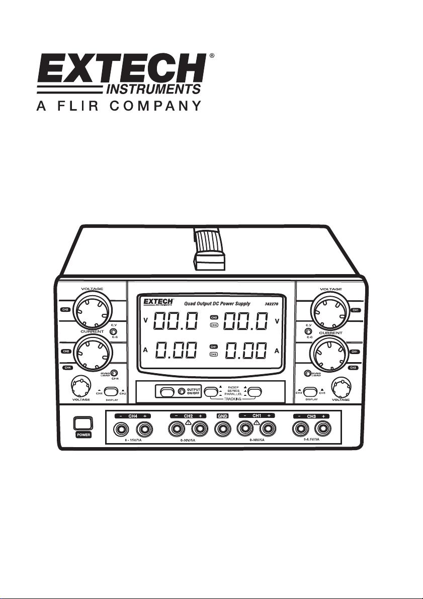
Model 382270
High Precision Quad Output
DC Power Supply
Page 2

Introduction
Congratulations on your purchase of the Extech 382270 DC Power Supply. The Model 382270 can be
used for many applications including bench testing, field service, hobby, educational, maintenance,
and telecommunication equipment use.
The Model 382270 is a high-precision DC regulated power supply with four outputs. Of which, two are
completely adjustable and two are semi-adjustable. The two adjustable outputs can be configured for
constant voltage or constant current. The two adjustable outputs can be connected in parallel or in
series. The 3 digit LED display indicates each of the two adjustable outputs.
The two semi-adjustable outputs (one is 3~6.5V/3A and the other is 8~15V/1A) have good stability and
ripple factor, and reliable overload protection to protect the unit against overloads or short circuits.
This power supply is shipped fully tested and calibrated and, with proper use, will provide years of
reliable service.
Safety Information
Safety Precautions
To ensure safe operation of the equipment and eliminate the danger of serious injury due to shortcircuit (arcing), the following safety precautions must be observed.
• Prior to connection of the equipment to the mains outlet, check that the available mains
voltage corresponds to the voltage setting of the equipment.
• Connect the mains plug of the equipment only to a mains outlet with an earth ground
connection.
• Do not place the equipment on damp or wet surfaces.
• Do not subject the equipment to direct sunlight or extreme temperatures.
• Do not subject the equipment to extreme humidity or dampness
• Replace a defective fuse only with a fuse of the original rating. Never short circuit the fuse or
the fuse housing
• Do not exceed the maximum permissible input rating.
• Comply with the warning labels and other info on the equipment.
• Do not insert metal objects into the equipment by way of the ventilation slots
• Do not place water-filled containers on the equipment
• Do not operate the equipment near strong magnetic fields (motors, transformer etc.)
• Do not subject the equipment to shocks or strong vibrations
• Keep hot soldering irons away from the equipment
• Allow the equipment to stabilize at room temperature before use
• Do not modify the equipment in any way
• Do not place the equipment face-down on any surface, table or work bench
• All service and repair must be performed by qualified service personal.
Cleaning the meter housing
Prior to cleaning the meter housing, disconnect the mains plug from the power outlet. Clean only
with a damp, soft cloth and a commercially available mild household cleaner. Ensure that no water
gets inside the equipment to prevent possible shorts and damage to the equipment.
2 382270-EU-EN-V2.2-1/12
Page 3

Power Supply Description
1. POWER button
2. Channel 4 Voltage adjustment
3. Channel 4 overload status LED
4. Channel 2 Current adjust knob
5. Constant Current / Voltage
status LED for CH 4
6. Channel 2 Voltage adjust knob
7. Voltage output display (CH 2/4)
8. Current output display (CH 2/4)
9. Current output display (CH 1/3)
10. Voltage output display (CH 1/3)
11. Channel 1 voltage output adjust
knob
12. Constant Voltage / Current
status LED for Channel 1
13. Current output adjust knob for Channel 1
14. Channel 4 overload status LED
15. Voltage output adjust knob for Channel 3
16. Positive terminal CH 3
17. CH1 / CH 3 display select button
18. Negative terminal CH 3
19. Positive terminal CH 1
20. SERIES / PARALLEL / INDEPENDENT tracking select button
21. Negative terminal CH 1
22. GND terminal
23. SERIES / PARALLEL / INDEPENDENT tracking select button
24. Positive terminal CH 2
25. Output ON-OFF status LED
26. Negative terminal CH 2
27. Output ON-OFF button
28. Positive terminal CH 4
29. Negative terminal CH 4
30. CH2 / CH 4 display select button
6
5
4
3
2
1
78 910
29
28
30 23
11
12
13
14
15
16
2224
252627
18
17
192021
3 382270-EU-EN-V2.2-1/12
Page 4

Operation
Independent Connections (Channels 1 and 2, adjustable outputs)
Set the tracking switches (19) and (22) to the spring out position (INDEP). Set the Output On/Off
switch (27) to the On position.
Constant Voltage (CV) Mode
1. Rotate the CC knob (4) for CH 2 or (13) for CH 1 to maximum and then turn on the power
supply.
2. Adjust CV knob (6) or (11) for the desired output.
3. The color of the CV/CC status LED (5) or (12) will turn green.
4. Current Limiting Note: For CV outputs in general, the CC adjustment should be set to
maximum, but, for this unit, the current limiting protection point can also be set arbitrarily. To
do so:
a) Turn on power
b) Rotate CC adjustment counter-clockwise to minimum
c) Short the positive and negative terminals
d) Rotate the CC adjustment clockwise to the desired current-limiting protection point.
Constant Current (CC) Mode
1. Turn on the power supply.
2. Rotate the CV knob (6) or (11) to maximum.
3. Rotate the CC adjustment (4) or (13) to minimum
4. Connect the required load.
5. Rotate CC adjust knob clockwise to reach the desired current value.
6. The color of the CV/CC status LED (5) or (12) will turn red.
4 382270-EU-EN-V2.2-1/12
Page 5

Series Connection (Channels 1 and 2, adjustable outputs)
1. Set the tracking switch (20) to the spring out position. Press in tracking switch (23).
2. In Series mode, the slave output will strictly track the master output voltage when the user
turns the master voltage adjust knob (11). The output voltage in Series mode can be set up to
double the maximum voltage available in Independent mode (voltage between terminals 19 &
26).
3. Ensure that both channels’ negative terminals are NOT connected to case ground. If they are,
a short circuit will occur.
4. When the two outputs are configured in Series, the voltage is controlled by the master output
knob, but the current adjustment for the two outputs is still independent. Therefore, ensure that
the CC adjust knob is rotated fully clockwise to maximum for the Series circuit to work
correctly.
5. The user must physically short the negative terminal of the Master output with the positive
terminal of the Slaved output.
Parallel Connection (Channels 1 and 2 adjustable outputs)
1. Press in both tracking switch (19) and tracking switch (23).
2. In Parallel mode, the two outputs will always be the same for any setting of the master voltage
knob (11). The slave CC indicator (5) will switch on.
3. In Parallel mode the CC adjustment (4) for the slave is not active. The user must adjust the CC
for the master output. The current available in parallel mode is up to twice the amount available
in other modes.
4. The user must short the two positive terminals.
5. The user must also short the two negative terminals.
5 382270-EU-EN-V2.2-1/12
Page 6

Specifications
Range Specifications
Electrical Specifications
Input voltage: 110~127VAC±10%; 220~240VAC±10% (switchable)
Output voltage and current: See table above
Line regulation:
For Two adjustable outputs:
CV: ≤ 1 x 10¯
CC ≤ 2 x 10¯
Two semi-adjustable outputs: ≤ 5mV
Load regulation:
Two adjustable outputs:
CV ≤ 5 x 10¯
CC ≤ 2 x 10¯
CH3 ≤30mV
CH4 ≤15mV
Ripple and noise:
Two adjustable outputs:
CV ≤ 1mV rms
CC ≤ 3mA rms
Fixed output: ≤ 2mV rms
Protection: current-limit
Display accuracy:
Volt-indication: LED ± (0.5%rdg+2 digits)
Amp-indication: LED ± (0.5%rdg+2 digits)
General Specifications
Display: Four 3-digit color-coded LED displays and four status LED lights
Dimensions: 260 x 160 x 370mm (10.2 x 6.3 x 14.6") (W x H x D)
Weight: 12 kg (26.4lbs)
Copyright © 2012 Extech Instruments Corporation (a FLIR company)
All rights reserved including the right of reproduction in whole or in part in any form.
Output1
(CH1)
Output2
(CH2)
Output3
(CH3)
0~30V/0~5A 0~30V/0~5A 3~6.5V/3A 8~15V/1A
4
+ 3mV
3
+ 3mA
4
+ 5mV
3
+ 5mA
www.extech.com
Output4
(CH4)
6 382270-EU-EN-V2.2-1/12
 Loading...