

Page 1
User's Guide
1000A 3-Phase Power Analyzer/Datalogger
Model 382090 (60Hz)
Model 382091 (50Hz)
Page 2

Warranty
EXTECH INSTRUMENTS CORPORATION warrants this instrument to be free of defects
in parts and workmanship for one year from date of shipment (a six month limited warranty
applies to sensors and cables). If it should become necessary to return the instrument for
service during or beyond the warranty period, contact the Customer Service Department at
(781) 890-7440 ext. 210 for authorization or visit our website www.extech.com for contact
information. A Return Authorization (RA) number must be issued before any product is
returned to Extech. The sender is responsible for shipping charges, freight, insurance and
proper packaging to prevent damage in transit. This warranty does not apply to defects
resulting from action of the user such as misuse, improper wiring, operation outside of
specification, improper maintenance or repair, or unauthorized modification. Extech
specifically disclaims any implied warranties or merchantability or fitness for a specific
purpose and will not be liable for any direct, indirect, incidental or consequential damages.
Extech's total liability is limited to repair or replacement of the product. The warranty set
forth above is inclusive and no other warranty, whether written or oral, is expressed or
implied.
Introduction
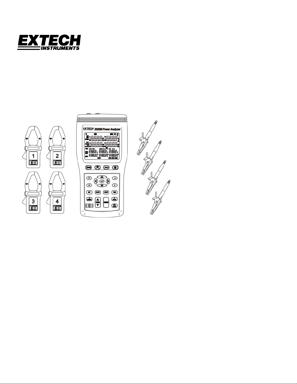
Congratulations on your purchase of the Extech 382090/382091 1000A 3-Phase Power
Analyzer Datalogger. Model 382090 is for use with 60Hz power systems. Model 382091
is for use with 50Hz power systems. This package includes four (4) clamp-on meters and
four (4) alligator clip leads that connect to the analyzer/datalogger. When the clamps and
test leads are connected to the circuit under test the user can view up to ten power
measurement displays. Also, up to 20,000 data sets can be automatically stored by the
analyzer/datalogger. Stored readings can later be transferred to a PC. Real-time logging
(readings recorded and transferred to PC at the same time) is also supported. Careful
use of these instruments will provide years of reliable service.
Features
• Ten display LCD screens capable of showing a multitude of power quality
parameters simultaneously
• Up to four current probes can be connected to the analyzer
• Measure single-phase 2-wire, single-phase 3-wire, three-phase 3-wire and three-
phase 4-wire systems
• True-RMS sensing for V, A, KW, KVAR, KVA, PF, θ, Hz, KWh, KVARh and KVAh
measurements
• Phase sequence indicator
• Backlit display
• Manual and Automatic Datalogging
• PC interface with 3-phase voltage/current waveform display & harmonic analysis
• Easy-to-use push-button operation
• Light weight and portable
2
382090 382091 V4.0 09/07
Page 3
Safety
This Operation Manual provides information and warnings essential for operating the
Model 382090/382091 in a safe manner. Before using this meter, be sure to carefully read
the following safety information.
DANGER
During high voltage measurements, incorrect measurement procedures could result in
injury or death, as well as damage to the meter. Please read this manual carefully and be
sure to understand its contents before using the meter.
• Do not use the meter if the test leads appear damaged
• Use extreme caution when working around bare conductors or bus bars,
Accidental contact with the conductor could result in electric shock
• To avoid damage to the meter do not exceed the specified maximum input limits
• Use the meter only as specified in this manual to ensure that the protection
provided by the meter is not impaired
SAFETY SYMBOLS
This symbol printed on the meter alerts the operator to consult
corresponding manual topics before using related meter functions
Dangerous voltages
Meter is protected throughout by double insulation or reinforced insulation.
When servicing, use only specified replacement parts.
Complies with EN-61010-1, IEC 1010-2-32
DANGER: Indicates that incorrect operation presents extreme danger of
accident resulting in death or serious injury to the user.
WARNING: Indicates that incorrect operation presents significant danger of
accident resulting in death or serious injury to the user.
CAUTION:
Indicates that incorrect operation presents possibility of injury to the
user or damage to the meter.
NOTE: Denotes items of advice related to the performance of the meter or to its
correct operation.
3
382090 382091 V4.0 09/07
Page 4

Installation Safety
CAUTION
• The meter is designed for indoor use and can be safely used at temperatures
ranging from 32 to 104
• Do not store or use the meter where it will be exposed to direct sunlight, high
temperature, high humidity, or condensation. If exposed to such conditions, the
meter may be damaged, the insulation may deteriorate, and/or the meter may
no longer meet the published specifications.
• The meter is not waterproof or dustproof
• Do not use the unit where it may be exposed to corrosive or explosive gases
Preparation Safety
o
F (0 to 40oC).
WARNING
• To prevent electrical shock, do not allow the meter to become wet and do not
handle the meter with wet hands.
• When working with live circuits, take all suitable precautions against accidents,
including the use of electrical safety gear such as rubber gloves, rubber boots,
and safety helmets.
Connection Safety
WARNING
• To prevent electrical shock, turn the power off before connecting the test leads.
• In order to prevent electrical shock and short-circuits, shut off the power to the
line under test before connecting the line under test to the voltage input
terminals.
CAUTION
The measurement input and synchronizing input are not isolated from each other.
Connecting either one means that the other is exposed and live with a danger of
electrical shock present. To avoid electrical shock, connect both terminals.
WARNING
To avoid electrical shock and/or meter damage, use caution when connecting test
leads to live components. The jaws of alligator clips can create a short circuit
between closely spaced live parts. Avoid making connections to feeder conductors or
bus bars at elevated potentials.
• Follow all city, state, and local codes. Obey posted instructions.
• Never assume that a circuit is de-energized, check it first.
• Always set up the measurement first and then connect test leads to the circuit.
• Make connections to the meter first, before connecting leads to a live circuit.
• Connect the ground lead first, then the voltage leads and the current probe.
Disconnect in reverse order.
4
382090 382091 V4.0 09/07
Page 5
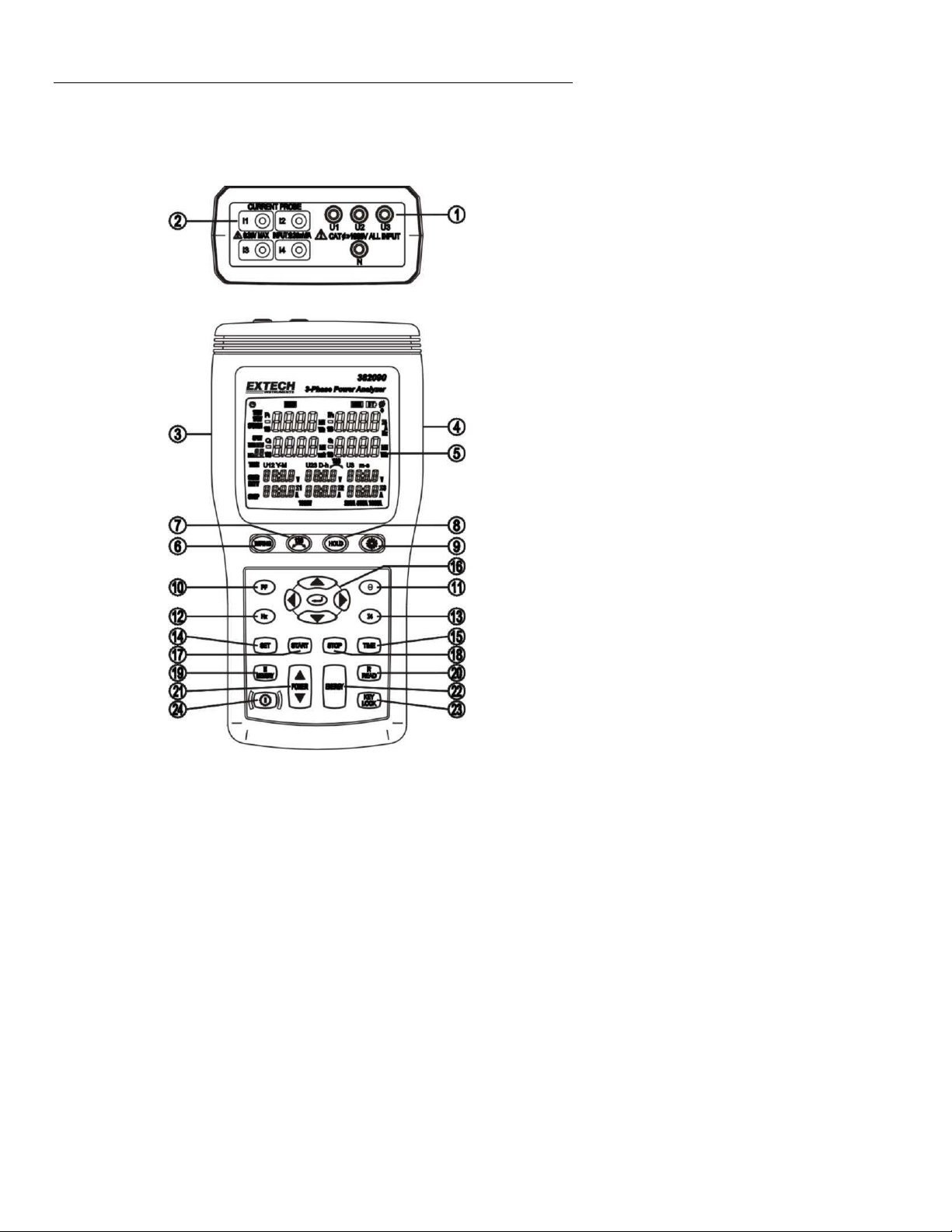
Analyzer Description
5
382090 382091 V4.0 09/07
Page 6
1. Input jacks for test leads (U1, U2, U3, N)
2. Input jacks for current probes (I1, I2, I3, I4)
3. Plug for external AC adaptor
4. Optical RS232 PC interface output
5. LCD display
6. WIRING key Select the type of electrical system under test using the WIRING key.
Select 1P2W (for signal-phase two-wire power lines), 1P3W (for signalphase three-wire power lines), 3P3W2M (for three-phase three-wire power
line without neutral using the two power meter method; use this selection
when measuring three-phase power with 2-current probe measurement
only) and 3P4W (for three-phase four-wire power lines with neutral)
7.
8. HOLD key Data hold function key, press HOLD key to freeze displayed reading (the
9. key Backlight function key, press to turn backlight on or off. The backlight will
10. PF key Press to view the power factor value (the PF icon is displayed)
11. Θ key Press to view the measured phase angle value (ψ icon is displayed)
12. Hz key Press to display the measured frequency (the Hz icon is displayed)
13. I4 key Press to display the I4 current probe value (the I4 icon is displayed)
14. SET key Press and hold the TIME key then press the SET key to enter the time set
15 TIME key Press to display the current date and time
16. ↵ Used when setting the date and time. Also used to recall manually
17. START key Press to start the automatic datalogging function
18. STOP key Press to stop/pause the automatic datalogging function. Press START to
19. MEMORY Press key to store one reading (set), the ‘M’ icon and the memory address
20. READ key Press to recall a manually stored data set
21. POWERPress to display the measured power. Use this button to cycle through the
22. ENERGY Press to display the total integrated power energy
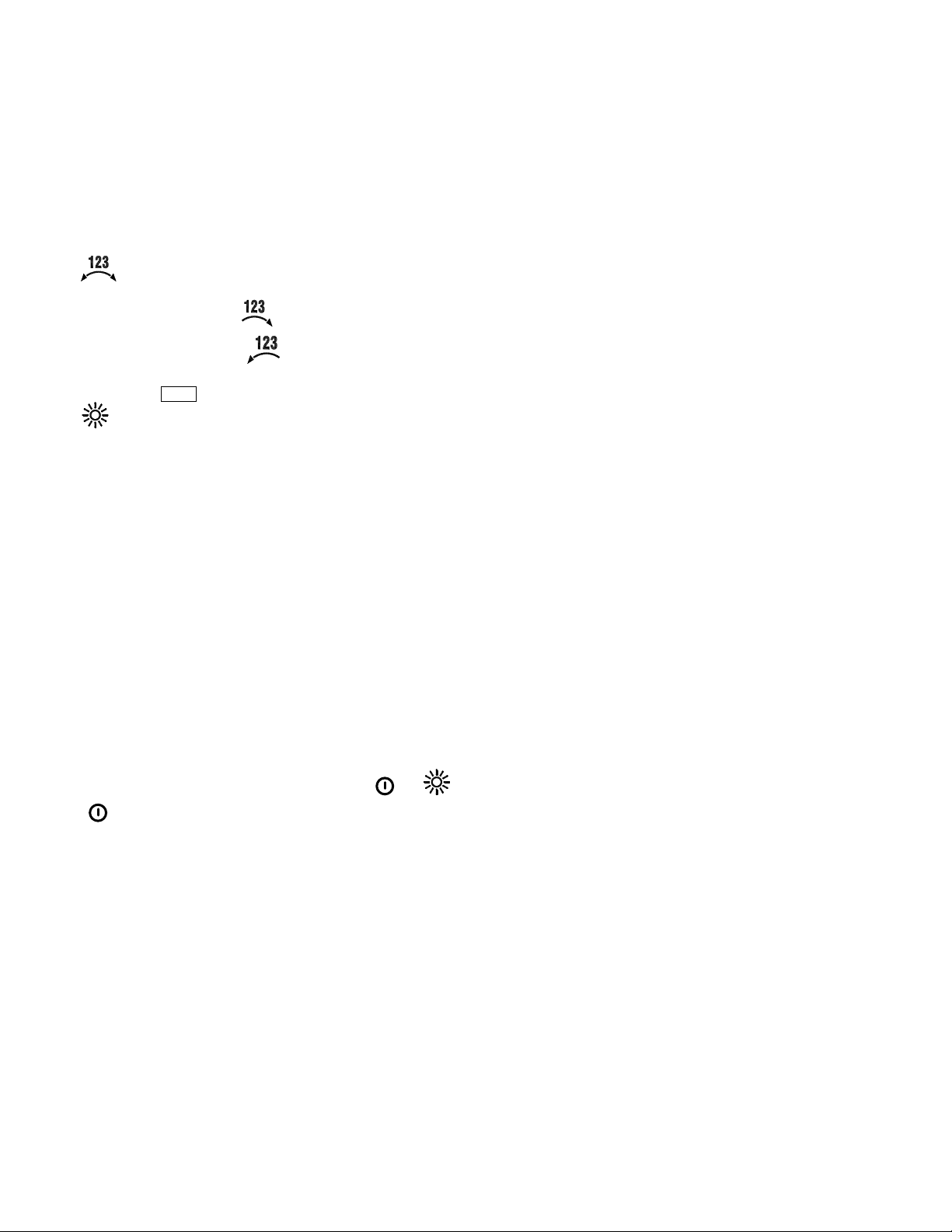
key Phase sequence detection function key. In the 3P4W mode, press and
hold this key to display the phase detection results as follows:
Normal phase
Reverse phase
HOLD icon will appear). Press HOLD again to exit Hold function.
switch off automatically after 30 seconds.
mode and datalogger sampling rate set mode
recorded data
resume recording.
will display (total manual memory size is 99 sets)
Pt123, Qt123 and St123 displays
23. KEY Lock Press to lock all of the keys except the
key Power on-off key
24.
6
and
keys
382090 382091 V4.0 09/07
Page 7
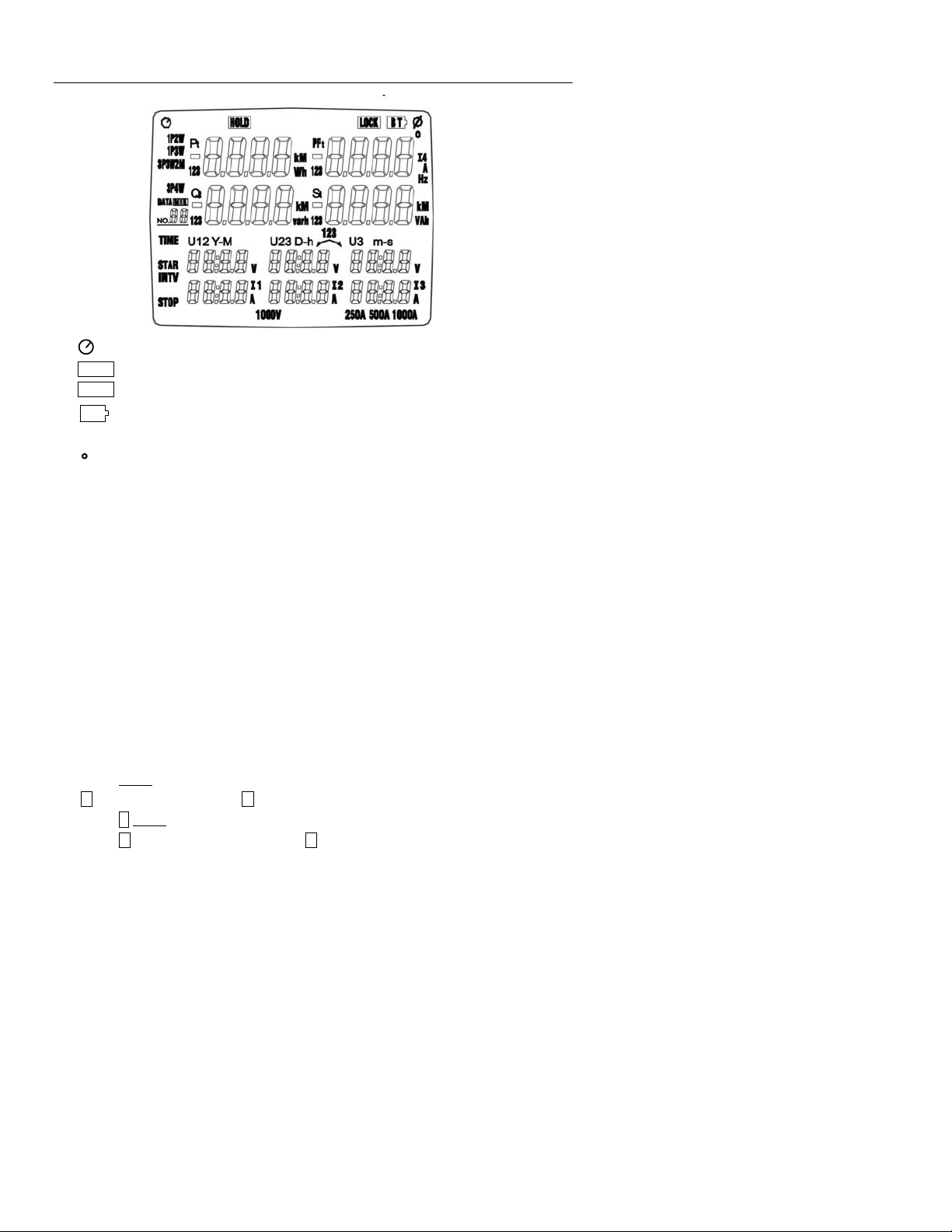
Display Description
: Auto power off indicator
HOLD : Display hold mode
LOCK : Lock-out mode
BT
: Low battery indication
ψ: Phase angle display
: Phase angle unit of measure (degrees)
1P2W: Single-phase two-wire power line indicator
1P3W: Single-phase three-wire power line indicator
3P3W2M: Three-phase three-wire power line indicator
3P4W: Three-phase four-wire power line indicator
P1: Phase 1 active power indicator
P2: Phase 2 active power indicator
P3: Phase 3 active power indicator
Pt: Total active power indicator and total active energy indicator
KW: Active power unit of measure (kilo-watt)
KWh, MWh: Active energy units of measure (kilo-watt hours and Mega-watt hours)
PF1: Phase 1 power factor indicator
PF2: Phase 2 power factor indicator
PF3: Phase 3 power factor indicator
PFt: Total power factor indicator
I4: Current probe No. 4 measurement indicator
Hz: Frequency unit of measure (hertz)
DATA No.××
M : Datalog record indicator; M displays momentarily each time a data set is recorded
DATA R No.××: Memory address for recalled reading
DATA M ××: Auto datalogging indicator; M flashes each time a data set is recorded.
: Manually datalogged memory address (01~99)
01 ~ 10: Memory blocks (20,000 max. data sets can be stored)
FF: Memory full indicator (when 10 memory blocks or 20,000 readings are filled)
7
382090 382091 V4.0 09/07
Page 8

Q1: Phase 1 reactive power indicator
Q2: Phase 2 reactive power indicator
Q3: Phase 3 reactive power indicator
Qt: Total reactive power indicator and total reactive energy indicator
Kvar: Reactive power unit of measure
Kvarh, Mvarh: Reactive energy unit of measure
S1: Phase 1 apparent power indicator
S2: Phase 2 apparent power indicator
S3: Phase 3 apparent power indicator
St: Total apparent power indicator and total apparent energy indicator
KVA: Apparent power unit of measure (Kilo-volt/amps)
KVAh: Apparent energy unit of measure (kilo-volt amp hours)
MVAh: Apparent energy unit of measure (mega-volt amp hours)
TIME: Current date and time indication
Y-M D-h m-s: Date and time
INTV: Automatic datalogging sampling interval setting indicator
START: Energy calculation start-time indicator
STOP: Energy calculation stop-time indicator
U1, V, A: Single-phase two-wire (1P2W) U1 voltage and I1 current measurement
U1, V, A, U2, V, A: Single-phase three-wire (1P3W) U1, U2 voltage and I1, I2 current
U12, V, I1, A, U23, V, I2, A: Three-phase, three-wire, two-power method (3P3W2M);
U1, V, A, U2, V, A, U3, V, A: Three-phase, four-wire (3P4W) U1, U2, U3 voltage and I1,
V: Voltage unit of measure
A: Current unit of measure (ampere)
1000V: Voltage range indication
250A, 500A, 1000A: Current range indication (Autoranging)
measurement
U12, U23 voltage and I1, I2 current measurement
I2, I3 current measurement
8
382090 382091 V4.0 09/07
Page 9

Operation
CAUTION: Turn the meter off before connecting to the equipment under test.
DANGER: Voltage input connectors U1 to U3 are common to input connector
N. Input connectors are not insulated; remove all unnecessary test leads.
DANGER: Voltage input connectors U1 to U3 are common to input connector
N. Input connectors are not insulated; remove all unnecessary test leads.
DANGER: Voltage input connectors U1 to U3 are common to input connector
N. Input connectors are not insulated; remove all unnecessary test leads.
WARNINGS
• Always set up the measurement first and then connect the test leads to the circuit.
• Make connections to the instrument first, before connecting leads to a live circuit.
• Connect the ground lead first and then the voltage leads and current probe;
disconnect in reverse order.
• Remove all test leads that are not in use.
Single-Phase 2-Wire (1P2W) Power System Measurement
U1 must be connected to the voltage source during the measurement of U2, U3, I1, I2 and I3
since U1 is the main signal source for the entire meter measurement system.
A: Line, N: Neutral, G: Ground; ¨ Face the arrow toward the load.
1P2W Wiring Connection Diagram
1. Press
2. Press the WIRING key to select 1P2W, the 1P2W annunciator will be displayed.
3. Connect the voltage test leads and current probe to the meter.
Connect the black voltage test lead to the “N” terminal.
Connect the red voltage test lead to the “U1” terminal.
Connect the I1 current probe output plug to the “I1” jack.
To measure ground leakage current, connect the I4 current probe output plug to the
key to turn the meter on
“I4” jack.
9
382090 382091 V4.0 09/07
Page 10

4. Connect the voltage test leads and current probe to the electrical equipment under test.
Connect the black voltage alligator clip to the Neutral Line “N”.
Connect the red voltage alligator clip to Line “A”.
Press the I1 current probe trigger to open the jaw and then fully enclose Line “A”.
To measure ground leakage current, press the I4 current probe trigger to open the
jaw and then fully enclose the Ground Line “G”.
5. To measure frequency, press the “Hz” key.
To measure the phase angle, press the “Θ” key.
To measure the ground leakage current, press the “I4” key.
To measure the power factor, press the “PF” key.
6. To measure energy, press the “ENERGY” key, the “Pt”, “Qt”, “St” and “PFt” or “ψt”
annunciators and energy integration start time will display.
The energy integration value and the current time will continually update. Press the “ ↵ ”
key to pause the energy calculation; the HOLD annunciator will display. Press the
HOLD key to exit the energy measurement mode.
CAUTION: Turn the meter off before connecting the voltage test leads
and the current probe to the electrical equipment under test.
10
382090 382091 V4.0 09/07
Page 11

Single-Phase 3-Wire (1P3W) Power System Measurement
U1 must be connected to the voltage source during the measurement of U2, U3, I1, I2 and I3
since U1 is the main signal source for the entire meter measuring system.
A, B: Line, N: Neutral, G: Ground; ¨ Face the arrow toward the load.
1P3W Wiring Connection Diagram
1. Press the
key to turn the meter on
2. Press the WIRING key to select 1P3W, the 1P3W annunciator will display.
3. Connect the voltage test leads and the current probe to the meter.
Connect the black voltage test lead to the “N” terminal.
Connect the red voltage test lead to the “U1” terminal.
Connect the yellow voltage test lead to the “U2” terminal.
Connect the I1 current probe output plug to the “I1” jack.
Connect the I2 current probe output plug to the “I2” jack.
To measure ground leakage, connect the I4 current probe output plug to the “I4” jack.
4. Connect the voltage leads and current probe to the electrical equipment to be tested.
CAUTION: Turn the meter off before connecting the voltage test leads and
the current probe to the electrical equipment under test.
Connect the black voltage alligator clip to the neutral line “N”.
Connect the red voltage alligator clip to line “A”.
Connect the yellow voltage alligator clip to line “B”.
Press the I1 current probe trigger to open the jaw and then fully enclose Line “A”.
11
Press the I2 current probe trigger to open the jaw and then fully enclose Line “B”.
12
To measure ground leakage current, press the I4 current probe trigger to open the
jaw and then fully enclose the ground line “G”.
5. Use the POWER key to select (P1, Q1, S1, PF1), (P2, Q2, S2, PF2) and (Pt, Qt, St,
PFt).
11
382090 382091 V4.0 09/07
Page 12

6. To measure frequency, press the “Hz” key.
To measure phase angle, press the “Θ” key.
To measure ground leakage current, press the “I4” key.
To measure power factor, press the “PF” key.
7. To measure energy, press the “ENERGY” key, the “Pt”, “Θt”, “St” and “PFt” or “ψt”
annunciators and the energy integration start time will display. The energy integration
value and the current time will be continually updated, press the “ ↵ ” key to pause the
energy calculation; the HOLD annunciator will display. Press HOLD to exit the energy
measurement mode.
12
382090 382091 V4.0 09/07
Page 13

Three-Phase 3-Wire (3P3W) Power System Measurement
U1 must be connected to the voltage source during the measurement of U2, U3, I1, I2 and I3
since U1 is the main signal source of the entire meter measurement system.
A, B, C: Line, G: Ground; ¨ Face the arrow toward the load
3P3W Wiring Connection Diagram
1. Press the
2. Press the WIRING key to select 3P3W2M; the 3P3W2M annunciator will display.
3. Connect the voltage test leads and current probe to the meter.
Connect the black voltage test lead to the “N” terminal.
Connect the red voltage test lead to the “U1” terminal.
Connect the yellow voltage test lead to the “U2” terminal.
Connect the I1 current probe output plug to the “I1” jack.
Connect the I2 current probe output plug to the “I2” jack.
4. Connect the voltage test leads and current probe to the electrical equipment to be tested.
Connect the black voltage alligator clip to the line “B”.
Connect the red voltage alligator clip to the line “A”.
Connect the yellow voltage alligator clip to the line “C”.
Press the I1 current probe trigger to open the jaw, and then fully enclose Line “A”.
Press the I2 current probe trigger to open the jaw, and then fully enclose the Line “C”.
5. Use the POWER key to select (P1, Q1, S1, PF1), (P2, Q2, S2, PF2) & (Pt, Qt, St,
PFt)
key to turn the meter on.
CAUTION: Turn the meter off before connecting the voltage test leads and
the current probe to the electrical equipment under test.
13
382090 382091 V4.0 09/07
Page 14

6. To measure frequency, press the “Hz” key.
To measure phase angle, press the “Θ” key.
To measure power factor, press the “PF” key.
7. To measure energy, press the “ENERGY” key, the “Pt”, “Θt”, “St” and “PF” or “ψt”
annunciators and the energy integration start time will display. The energy integration
value and the current time will continually update, press “ ↵ ” key to pause the energy
calculation; the HOLD annunciator will display. Press HOLD to exit the energy
measurement mode.
14
382090 382091 V4.0 09/07
Page 15

Three-Phase 4-Wire (3P4W) Power System Measurement
U1 must be connected to the voltage source during the measurement of U2, U3, I1, I2 and I3
since U1 is the main signal source of the entire meter measuring system.
A, B, C: Line, N: Neutral, G: Ground; ¨ Face the arrow toward the load.
3P4W Wiring Connection Diagram
1. Press the
key to turn the meter on.
2. Press the WIRING key to select 3P4W; the 3P4W annunciator will display.
3. Connect the voltage test leads and the current probe to the meter.
Connect the black voltage test lead to the “N” terminal.
Connect the red voltage test lead to the “U1” terminal.
Connect the yellow voltage test lead to the “U2” terminal.
Connect the blue voltage test lead to the “U3” terminal.
Connect the I1 current probe output plug to the “I1” jack.
Connect the I2 current probe output plug to the “I2” jack.
Connect the I3 current probe output plug to the “I3” jack.
Connect the I4 current probe output plug to the “I4” jack.
4. Connect the voltage test leads and current probe to the electrical equipment to be tested.
CAUTION: Turn the meter off before connecting the voltage test leads and the
current probe to the electrical equipment under test.
Connect the black voltage alligator clip to the neutral line “N”.
Connect the red voltage alligator clip to line “A”.
11
Connect the yellow voltage alligator clip to line “B”.
12
Connect the blue voltage alligator clip to line “C”.
13
Press the I1 current probe trigger to open the jaw and then fully enclose Line “A”.
14
Press the I2 current probe trigger to open the jaw and then fully enclose Line “B”.
15
Press the I3 current probe trigger to open the jaw and fully enclose Line “C”.
16
Press the I4 current probe trigger to open the jaw and fully enclose neutral line “N”.
15
382090 382091 V4.0 09/07
Page 16

5. Press the POWER key to select (P1, Q1, S1, PF1), (P2, Q2, S2, PF2), (P3, Q3, S3,
PF3) or (Pt, Qt, St, PFt) groups.
6. To measure frequency, press the “Hz” key.
To measure phase angle, press the “Θ” key.
To measure neutral line current, press the “I4” key.
To measure power factor, press the “PF” key.
7. To measure energy, press the “ENERGY” key, the “Pt”, “Θt”, “St” and “PF” or “ψt”
annunciators and the energy integration start time will display. The energy integration
value and the current time will continually display, press the “ ↵ ” key to pause the
energy calculation; the HOLD annunciator will display. Press the HOLD key to exit the
energy measurement mode.
I4 Current Measurement
1. Press the
2. Press the “I4” key.
3. Connect the I4 current probe output plug to the “I4” jack.
4. Press the I4 current probe trigger to open the jaw and then fully enclose the desired measured
wire.
5. Read the I4 value, if the measured current value is greater than 250A, the “OL” symbol will
appear.
key to turn the meter on.
16
382090 382091 V4.0 09/07
Page 17

Manual Datalogger Record and Recall Mode
Clear memory data
1. Press the
2. Press and hold the MEMORY key and then press the
on; the “CLr” annunciator will display and all the manually logged data will be erased.
Manually record data
1. Press the MEMORY key once to store one reading (1 set). The M annunciator will
display momentarily along with the memory address.
2. Memory size for the manually recorded data is 99 sets max.
Recall manually stored data
1. Press the READ key and the R annunciator will display.
2. Use the keys to scroll through the stored data; the location (address) for each data
will also display.
3. Press the “ ↵ ” key to exit the recall mode.
Automatic Datalogging
Clearing memory data
As a safeguard against accidentally deleted logged data the Power Analyzer memory
can only be cleared through the software.
Please refer to the software operation section for instructions to clear the data.
Setting the Calendar Clock and the Automatic Datalogging Sampling Interval
1. Press the TIME key and then quickly press the SET key. Seconds will start blinking.
2. Use the keys to set the current YEAR-month, DAY-hour, minutes-seconds
3. Press the “ ↵ ” key to access the sampling interval mode; the “INTV” annunciator will
display.
4. Use the keys to select the sampling interval (5 seconds, 30 seconds, 1 minute or
2 minutes).
5. Press the ↵ key to exit this mode.
key to turn the meter off.
key again to turn the meter
Automatic Datalogging Operation
1. Press the START key to begin automatic datalogging: DATA M×× (block number) will
display. The M annunciator will appear each time a reading is recorded.
2. Press the STOP key to pause logging; press START to resume.
3. Data can be recorded in up to 10 memory blocks; the current block number is
displayed while logging (the maximum recording capacity is 20,000 readings).
4. When the maximum block or maximum reading limit is reached, the “FF” annunciator
will be displayed and datalogging will stop.
Downloading Data to a PC
Please refer to the software operation section for data download instructions..
17
382090 382091 V4.0 09/07
Page 18

Phase Sequence Measurements
1. Press the
2. Use the WIRING key to select 3P4W.
3. Connect the voltage test leads to the meter.
Connect the red voltage test lead to the “U1” terminal.
Connect the yellow voltage test lead to the “U2” terminal.
Connect the blue voltage test lead to the “U3” terminal.
4. Connect the voltage test leads to the electrical equipment to be tested.
CAUTION: Turn the meter off before connecting the voltage test leads and the
current probe to the electrical equipment under test.
Connect the red voltage alligator clip to power line “A” phase.
Connect the yellow voltage alligator clip to power line “B” phase.
Connect the blue voltage alligator clip to power line “C” phase.
5. U1, U2 and U3 measured voltages must be greater than 30V.
key to turn the meter on.
Press and hold the “
If the phase sequence is clockwise, the “
If the phase sequence is counter-clockwise, the “ ” annunciator is displayed.
Release the “
Voltage/Current Waveform and Harmonic Analyzer
Please refer to the software operation section for waveform and harmonic measurement
details.
Disabling the Auto Power-Off Feature
The meter automatically enters the sleep mode after approx. 30 minutes to conserve
battery power.
1. To disable this feature:
Press the
Press and hold the HOLD key and then press the
auto power off symbol “
2. The Auto power off mode is enabled each time the meter is turned on. It is automatically
disabled in the following modes:
ENERGY mode
Automatic datalogging
When Meter is connected to PC
key to turn the meter off.
” key.
” annunciator is displayed.
” key to exit this measurement mode.
key to turn the meter on. The
” will switch off indicating Auto Power off is disabled.
18
382090 382091 V4.0 09/07
Page 19

RS-232 PC Interface
Connect the Optical Interface connector to the 382090 Power Analyzer (middle pin is keyed
for correct orientation). Connect the 9-pin female connector to the 9-pin serial PC port (COM1
or COM2).
PC Requirements
• 486-33 IBM compatible PC or better
• One CD-ROM drive
• Available serial port.
• Windows 95, 98, 2000, NT, ME, XP Operating System
Installing the Windows Application Program
1. Place the supplied software CD in the PC CD-ROM drive
2. Wait for “Autorun” to start and follow the on-screen instructions
3. If “Autorun” does not start, click on “Start” then “Run”. Type the drive letter of the CDROM and :\VB\Disk1\Setup.exe and click OK (To install the LabVIEW version, type the
drive letter and :\LV\installer\Setup.exe and click OK).
4. Change the path if necessary or choose install the program to its default location.
5. Launch the program by double clicking the program file in the location where it was
saved during installation.
6. Remember not to run the supplied software until the meter is properly connected to the
PC as described earlier.
Software Operation
Instructions on using the software are included on the CD-ROM.
Open the file called 382090 Software Manual.pdf
to access the manual.
19
382090 382091 V4.0 09/07
Page 20

Specifications
General Specifications
Maximum voltage between voltage input terminals and earth ground: 1000 Vrms
Maximum rated working voltage for current input: 0.35Vrms
Maximum current for current probe: 1000A rms
Display: Ten (10) 4-digit LCD displays (maximum reading 9999)
Batteries 8pcs, 1.5VAA
Battery life: approx. 50 hours
AC Adaptor 12V DC, 300mA
Auto power off: After approx. 30 minutes
Low battery indication:
Backlight display time: Automatically turns off approx. 30 seconds
Sampling rate: Approx. 1 display update every 2 seconds (digital display)
Waveform and harmonic analyzer: 54 samples per period
Current probe jaw opening diameter: Cables ψ40mm
Operating temperature and humidity: 32 to 104
Temperature coefficient: 0.1 × (specified accuracy) / <64 or >82
Storage temperature and humidity: 14 to 140
Dimensions (meter): 9.2(L) x 4.6(W) x 2.1(H)”; [235(L) × 117(W) × 54(H)mm]
Dimensions (Current probes): 7.6(L) x 3.5(W) x 1.6(H)”; [193(L) × 88(W) × 40(H)mm]
Weight: Meter: approx. 25.8 oz (730g); Current probe: approx. 11.6oz (333g)
This meter is intended for indoor use and protected, against the users,
Safety
by double insulation per EN61010-1 and IEC61010-1 2nd Edition (2001)
to CAT III 1000V; Pollution Degree 2. The meter also meets UL 61010A1, First Edition
UL Listed The UL mark does not indicate that this product has been evaluated for
the accuracy of its readings.
Per IEC1010 Measurement Installation Category
MEASUREMENT CATEGORY I: Equipment of OVERVOLTAGE CATEGORY I is equipment for connection to
circuits in which measures are taken to limit the transient overvoltages to an appropriate low level. Note
– Examples include protected electronic circuits.
MEASUREMENT CATEGORY II: Equipment of OVERVOLTAGE CATEGORY II is energy-consuming
equipment to be supplied from the fixed installation.
Note – Examples include household, office, and laboratory appliances.
MEASUREMENT CATEGORY III: Equipment of OVERVOLTAGE CATEGORY III is equipment in fixed
installations.
Note – Examples include switches in the fixed installation and some equipment for industrial use with
permanent connection to the fixed installation.
MEASUREMENT CATEGORY IV: Equipment of OVERVOLTAGE CATEGORY IV is for use at the origin of the
installation.
Note – Examples include electricity meters and primary over-current protection equipment
BT
is displayed when battery voltage falls low
o
F (0 to 40oC); R.H. <80% non-condensing
o
F (-10 to 60oC); R.H. < 70% non-
condensing
o
F (<18 or >28oC)
20
382090 382091 V4.0 09/07
Page 21

Electrical Specifications
Accuracy: ± (% of reading + number of digits) at 64 to 82
o
F (18 to 28oC) with relative
humidity to 80%
AC Voltage True rms measurements (V)
Range Resolution Accuracy
± (0.5%rdg + 10d)
(>80V)
999.9V
0.1V
Input
impedance
2MΩ 1000Vrms
Overload
protection
Nominal
frequency
50Hz (382091)
60Hz (382090)
Note: Minimum Voltage; 50V (0V displayed below 50V)
• Display: RMS voltage value for each channel
AC Current True rms Measurement (A) Autoranging
Ranges Resolution
250.0A
500.0A
0.1A
999.9A
Accuracy
(including current
probe)
±(2%rdg + 20d)
Current probe
output
0.35mV/A 1000Arms
Overload
protection
Nominal
frequency
50Hz (382091)
60Hz (382090)
Note: Minimum Current; 3A (0A displayed below 3A)
Display: RMS current value for each channel
•
Active Power measurement P (KW)
Range Resolution Accuracy (PF=1) Power factor influence (PF=0.5)
999.9KW 0.1KW ± (1.5%rdg + 20d) ± (1%rdg + 10d)
Display: Active power of each channel and the sum of multiple channels
•
Polarity display: For influx (consumption) no symbol; For outflow (regenerative) “ - ” sign
•
Apparent Power measurement S (KVA)
Range Resolution Accuracy (PF=1) Power factor influence (PF=0.5)
999.9KVA 0.1KVA ± (1.5%rdg + 20d) ± (1%rdg + 10d)
Measurement method: Calculated from RMS voltage U and RMS current I.
•
Displays: Apparent power of each channel and the sum of multiple channels.
•
• Polarity display: Positive assumed
Reactive Power measurement Q (KVAR)
Range Resolution Accuracy (PF=1)
Power factor influence
(PF=0.5)
999.9KVAR 0.1KVAR ± (1.5%rdg + 20d) ± (1%rdg + 10d)
Measurement method: Calculated from apparent power S and active power P.
•
Displays: Reactive power of each channel and the sum of multiple channels.
•
Polarity display: For phase lag (LAG) current is behind voltage: No symbol. For LEAD
•
phase (LEAD: current ahead of voltage): “-” sign
21
382090 382091 V4.0 09/07
Page 22

Power Factor measurement (COSψ)
Range Resolution Accuracy
-1 ~ 0 ~ +1 0.001 ± (3%rdg + 30d)
Measurement method: Calculated from apparent power S and active power P.
•
Displays: Power factor of each channel and the sum of multiple channels.
•
Polarity display: For phase lag (LAG) current is behind voltage: No symbol; for phase
•
lead (LEAD) current is ahead of voltage: “-” sign
Phase angle measurement (ψ)
Range Resolution Accuracy
>50A: ± 3°+ 30digits,
±11° to 90° 0.1°
25 to 50A: ± 4° + 40digits
(<25A unspecified)
Measurement method: Calculated from power factor COSψ
•
Display item: Phase angle of each channel and the sum of multiple channels.
•
Polarity display: For phase lag (LAG: current is behind voltage): No symbol. For phase
•
lead (LEAD: current is ahead of voltage): “-”.
Frequency measurement (Hz)
Range Resolution Accuracy Measurement source
60HZ 0.01Hz
Measurable input range : > 30V
•
(0.5%rdg + 1d)
±
Voltage U1 > 80V
Three Phase Sequence Detection
Input voltage range Normal phase indication Reverse phase indication Meas. source
3P > 30V
U1, U2 and U3
Active Power Energy measurement (KWh)
Range Resolution
Active power
accuracy
Timer interval Timer Accuracy
3.999KWh 0.001KWh
39.99KWh 0.01KWh
399.9KWh 0.1KWh
3.999MWh 0.001MWh
± (1.5%rdg + 20d) 1 sec
± 50ppm at 77
o
C)
(25
39.99MWh 0.01MWh
119.3MWh 0.1MWh
Measurement display: Displays total active power consumption
•
Apparent Power Energy measurement (KVAh)
Range Resolution
Apparent power
accuracy
Timer interval Timer Accuracy
3.999KVAh 0.001KVAh
39.99KVAh 0.01KVAh
399.9KVAh 0.1KVAh
3.999MVAh 0.001MVAh
± (1.5%rdg + 20d) 1 sec
± 50ppm at 77
o
C)
(25
39.99MVAh 0.01MVAh
119.3MVAh 0.1MVAh
Measurement display: Displays total apparent power energy (sum of absolute values).
•
22
382090 382091 V4.0 09/07
o
F
o
F
Page 23

Reactive Power Energy measurement (Kvarh)
Range Resolution
Reactive power
accuracy
3.999Kvarh 0.001Kvarh
39.99Kvarh 0.01Kvarh
Timer interval Timer Accuracy
399.9Kvarh 0.1Kvarh
(1.5%rdg + 20d)
±
1 sec ±50ppm at 77
3.999Mvarh 0.001Mvarh
39.99Mvarh 0.01Mvarh
119.3Mvarh 0.1Mvarh
Measurement display: Displays total reactive power consumption
•
Harmonic measurement (for use with PC on-line analyzer only)
Order Accuracy Harmonic Source
1 ~ 27
3%THD
±
U1, U2, U3 > 100V; I1, I2, I3 > 50A 54
Probes and Accessories
Current Clamp (4pcs)
Input 1000A AC maximum
Output 0.35mV/A
Safety CAT III 600V per IEC61010-1, Pollution Degree2.
: IEC 61010-1 2nd Edition and IEC61010-2-032
Voltage Test Leads (4pcs)
Safety CAT III, 1000V, AC 10A Max
Alligator Clips (4pcs)
Safety CAT III, 1000V, AC 10A Max
o
F (25oC)
No. of samples
per period
23
382090 382091 V4.0 09/07
Page 24

Maintenance
Cleaning
Periodically wipe the case with a dry cloth. Do not use abrasives or solvents.
Battery Replacement
WARNING: To avoid electrical shock, remove the test leads and current probe
before replacing the batteries.
1. The LCD will display
operating levels.
2. Disconnect all test leads and current probes and press the
3. The battery cover is secured at the bottom of the meter case by two screws. Remove
these screws to access the battery compartment.
4. Replace the batteries observing polarity and reassemble the meter.
BT
(low battery) when the battery power falls below proper
key to turn the meter off.
Calibration and Repair Services
Extech offers repair and calibration services for the products we sell. Extech also
provides NIST certification for most products. Call the Customer Service Department for
information on calibration services available for this product. Extech recommends that
annual calibrations be performed to verify meter performance and accuracy.
All rights reserved including the right of reproduction in whole or in part in any form.
Support Hotline (781) 890-7440
Tech support: Ext. 200; Email: support@extech.com
Repair/Returns: Ext. 210; Email: repair@extech.com
Website: www.extech.com
Copyright © 2004 Extech Instruments Corporation
24
382090 382091 V4.0 09/07
 Loading...