

Page 1
User Manual
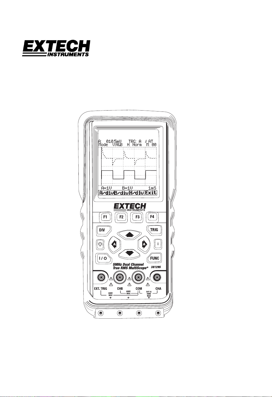
Model 381295 and 381295-220
5MHz Dual Channel
True RMS Handheld Oscilloscope
Page 2

Table of Contents
Introduction ........................................................................................ 3
Main Features .........................................................................................................3
Safety................................................................................................... 3
Safety Precautions .................................................................................................. 3
Safety Symbols .......................................................................................................3
Quick-Start Manual.............................................................................4
Power on and off ..................................................................................................... 4
Division, Trigger and Function key..........................................................................4
Input Terminals ........................................................................................................4
Command (F1-F4), Arrow, Backlight and Help key ................................................. 4
Primary Menu Map..................................................................................................5
Positioning the waveform on the screen .................................................................5
Division key map ..................................................................................................... 6
Changing Vertical (A/div or B/div) division ..............................................................7
Changing Horizontal division................................................................................... 7
Trigger key map ......................................................................................................8
Trigger level control................................................................................................. 8
Function key map....................................................................................................9
Specifications...................................................................................10
General Specifications ..........................................................................................10
Oscilloscope Function ........................................................................................... 11
Digital Multimeter Functions..................................................................................12
Product Description.........................................................................14
LCD Area............................................................................................................... 14
Keys Area..............................................................................................................15
Terminal Area ........................................................................................................17
Operation .......................................................................................... 18
Powering the Meter ............................................................................................... 18
Changing Backlight ...............................................................................................18
Making Selections in a Menu ................................................................................18
Frequency measurements for CHA....................................................................... 19
Freezing the screen ..............................................................................................19
Changing the Graphic Representation..................................................................20
Acquiring the Waveform........................................................................................21
Triggering on a Waveform..................................................................................... 22
Setting Trigger level (on NORmal trigger mode)...................................................22
Making a single acquisition ................................................................................... 23
Setting Trigger mode (Tmode) .............................................................................. 23
Setting AUTO Trigger Level .................................................................................. 24
Setting Normal Trigger mode ................................................................................ 24
Setting Trigger Slope............................................................................................. 25
Storing and Recalling Screens..............................................................................25
Storing Screen.......................................................................................................25
Recalling Screen ................................................................................................... 26
PC Interface and Datalogging Sof tware......................................... 27
Maintaining the Meter ......................................................................30
Battery Replacement........................................................................................... 269
Appendices....................................................................................... 32
Troubleshooting guide........................................................................................... 32
Warranty, Repair, and Technical Support….............................…...32
2
381295 V1.4V 10/06
Page 3
Introduction
Main Features
• Rechargeable batteries and AC Adaptor:
Model 381295 (120V, 60Hz)
Model 381295-220 (240V, 50Hz)
• RS-232C PC interface for viewing, saving, and printing measurement and
waveform data.
• Dual Channel operation plus Auto Calibration features.
• Automatic settings for horizontal and vertical divisions.
• DC to 5MHz bandwidth
• Built-in auto ranging True-RMS digital MultiMeter
• Auto ranging
• Data hold and run modes.
• Backlit display with Low battery indication.
• Display Type: Super-Twist 132 x 128 pixels.
• Designed to comply with safety standards: UL3111 and CSA C22.2 No.1010-1
Safety
Attention
Carefully read the following safety information before using this instrument.
Safety Precautions
Specific warning and caution statements, where they apply, will be found throughout the
manual.
A ‘Caution’ identifies conditions and actions that may damage the instrument. A
‘Warning’ identifies conditions and actions that pose hazard(s) to the user.
Symbols used on this instrument and in this manual are explained in the next table.
Warning
To avoid electrical shock, use only the supplied power supply.
See explanation in manual
Dangerous Voltage
Double Insulation (Protection Class)
Earth (Ground)
Either AC or DC
DC – Direct Current
AC – Alternating Current
Fuse
3
381295 V1.4V 10/06
Page 4
Quick-Start
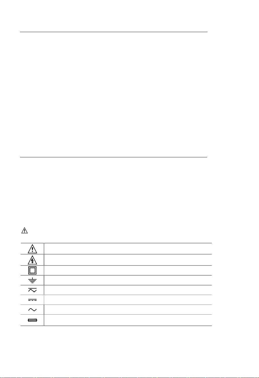
Power On and Off
1.Pressing and holding this button for 2 to 3
seconds will turn the unit on. Pressing this
button again will turn the power off.
Division, Trigger and Fu nction key
1 Division key:
Adjusts vertical division or Horizontal
division.
2 Trigger key:
Adjusts Trigger level.
Selects Single shot mode.
Selects trigger setup.
3 Function key:
Selects Scope Setup.
Selects general setup.
Input Terminals
1 Channel A:
Always use the red channel A input for single
input measurements.
2 Channel B:
For measuring two signals, use Channel B with
Channel A.
3 Common:
Use the black common as signal ground for low frequency measurements and for
ACV, DCV, Ohm, and Continuity measurements.
4 External trigger:
The EXT.TRIG input accepts external trigger signals.
Command (F1-F4), Arrow, Backlight and Help key
1
Function Command keys:
F1 through F4 are command ‘soft’ keys.
Their functions change with each screen.
2 Four arrow keys:
These keys serve as the primary means
of navigating the instrument’s menus and
operating displays.
3 Help key:
General information for the meter is available with a press of this key.
4 Display back light:
Press this button to turn on the backlight. To turn the back light off, press this button
again.
4
381295 V1.4V 10/06
Page 5
Quick-Start
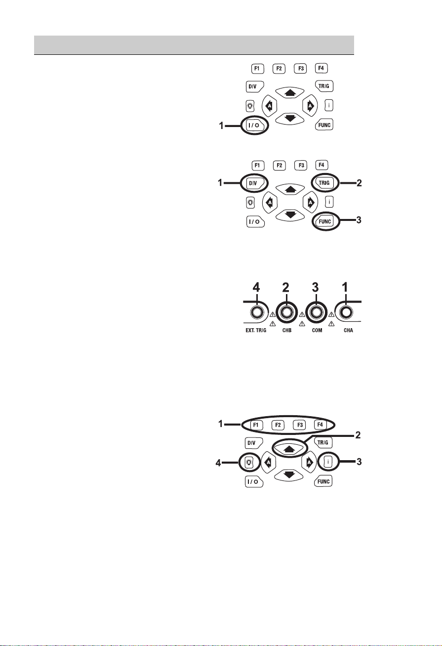
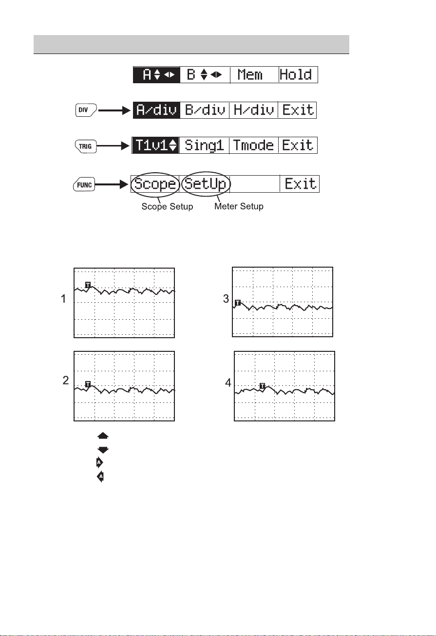
Primary Menu Map
Default Menu
Division Menu
Trigger Menu
Function Menu
Positioning the Waveform on the Screen
1. Pressing
2. Pressing
3. Pressing
4. Pressing
¸
moves the waveform up.
moves the waveform down.
moves the waveform left.
moves the waveform right.
5
381295 V1.4V 10/06
Page 6
Quick-Start
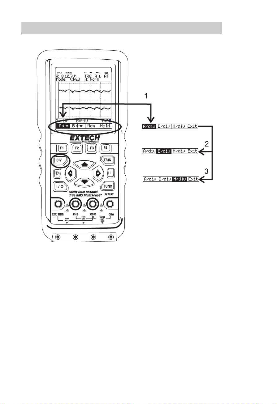
Division key map
1
Pressing DIV calls up the default division menu.
2 Press F2 to control the Channel B Vertical Division.
3 Press F3 to change the Horizontal Division.
4 Press F4 to exit.
6
381295 V1.4V 10/06
Page 7
Quick-Start
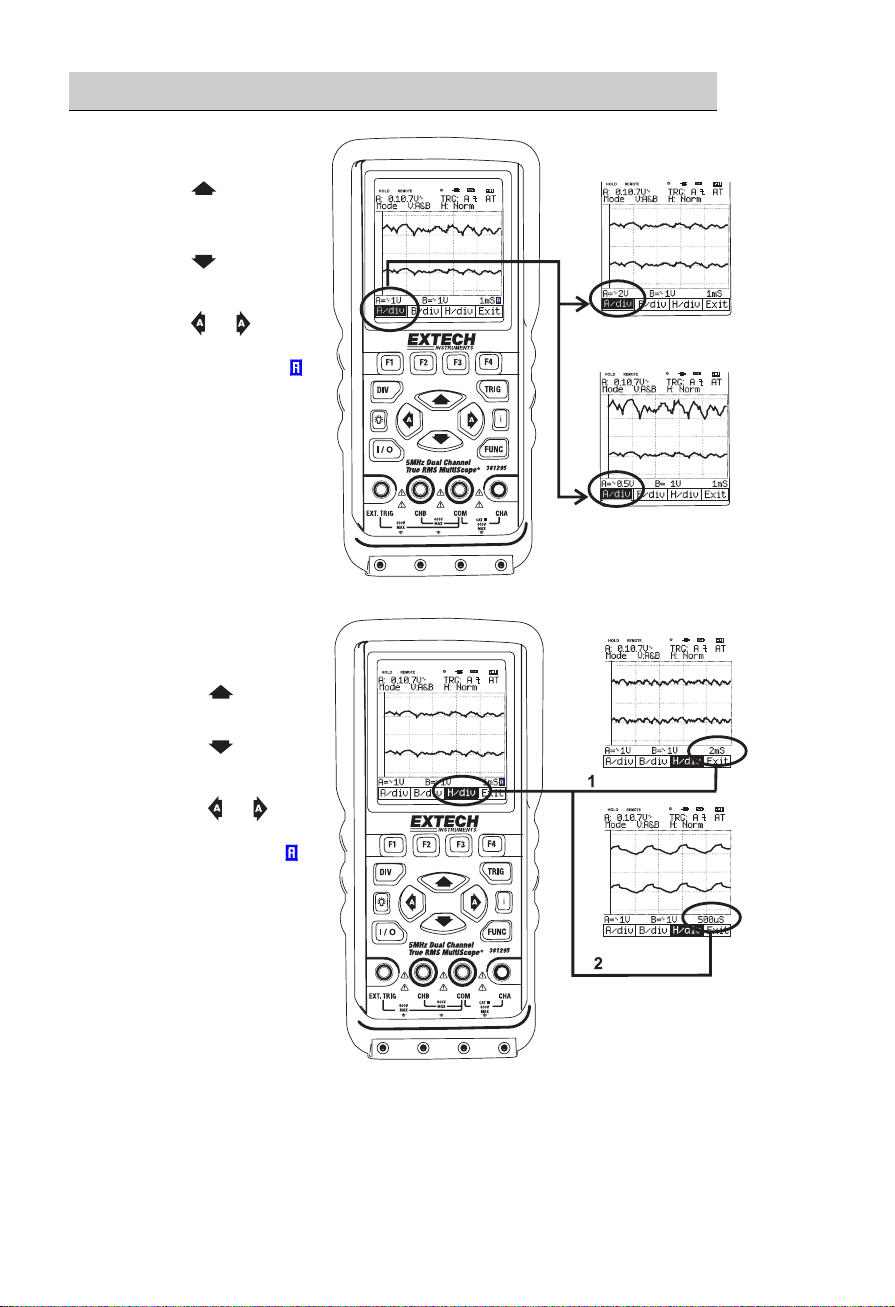
Changing Ve rtical (A/div or B/div) division
1 Pressing increases
CHA vertical division
(A/div).
2 Pressing
CHA vertical division
(A/div).
3 Pressing
change Div from
MANUAL to AUTO(
Changing Horizontal
division
1 Pressing increases
Horizontal division
(H/div).
2 Pressing
decreases Horizontal
division (H/div).
3 Pressing
change Div from
MANUAL to AUTO(
decreases
or will
).
or will
).
7
381295 V1.4V 10/06
Page 8
Quick-Start
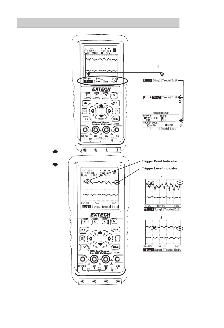
Trigger key map
1
Press TRIG to
display the
TRIGGER
default menu.
2 Press F2 for
Single shot mode.
3 Press F3 for
TRIGGER
SETUP.
4 Press F4 to exit.
Trigger level control
1 Pressing
increases the
Trigger level.
2 Pressing
decreases the
Trigger level.
8
381295 V1.4V 10/06
Page 9
Quick-Start
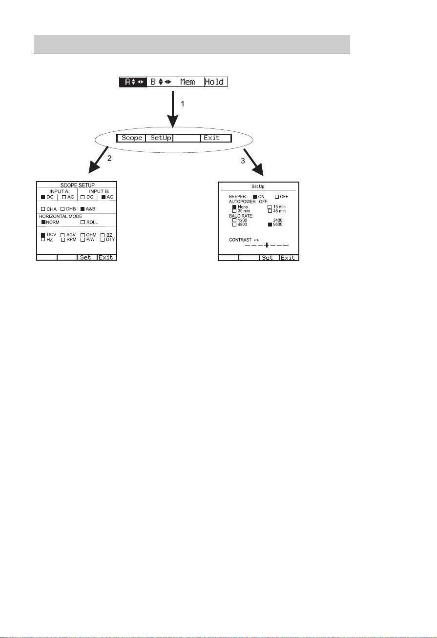
Function key map
1 Press FUNC to display the FUNCtion default menu.
2 Press F1 for SCOPE SETUP.
3 Press F2 for General SETUP. Press F4 to exit.
9
381295 V1.4V 10/06
Page 10

Specifications
General Specifications
Operational Temperature: +32°F to +122°F (0°C to +50°C)
Operational Relative Humidity: < 75%
Storage conditions: -4°F to 140°F (-20°C to +60°C); < 75%RH
Temperature Coefficient: 0.1 x (Specified Accuracy) per °C for temperature
Max. Voltage Input and Ground: DC or AC 600Vrms
Basic DC Accuracy: 0.3%
Scope Bandwidth: 5 MHz
MultiMeter AC Bandwidth: 20 kHz
Power Supply: Ni-MH Battery 4.8V (1.2V x 4 cell)
Battery Life: 4 Hours with Backlight OFF, 3 Hours with Backlight
Battery Charge Time: 3 Hours approx.
AC Adaptor/Charger: Class-2 transformer,
Display Type: Super-Twist 132 x 128 pixels
Equipment Dimensions: 3.5” (90mm) width x 7.7” (195mm) depth x 1.6”
Equipment Weight: 1.0 lbs
<64.4°F (18°C) to >82.4°F (28°C)
ON
Input: 120V AC 60Hz (381295)
Input: 240V AC 50Hz, (381295-220)
Output: 9V DC 1A
(40mm) height
. (460g) approx.
10
381295 V1.4V 10/06
Page 11

Oscilloscope Function
Horizontal
Sample Rate
Record Length
Sample / Division 25
Modes Single shot, Roll, Normal
Accuracy 0.01%
Sweep Rate 1uS to 5S in 1, 2, 5 sequence
25 MS/s (Dual CH mode)
50 MS/s (Single CH mode)
512 single shot mode
256 in all modes
Vertical
Bandwidth 5MHz
Resolution 8 Bit
Channels Dual
Coupling AC, DC
Input impedance
Accuracy ±3% reading + 0.1 x range; (“0” reference at center scale)
Max. Input Volts DC or AC 600Vrms
Volts / Division 50 mV to 500V in 1, 2, 5 sequence
1 MΩ
Triggering
Type CHA, CHB, External
Coupling AC, DC
Slope
Internal Trigger
Sensitivity
Rising (↑) or Falling (↓) edge
2 / 20 Division
Waveform Memory
Waveform Memory 16 Screen shots
11
381295 V1.4V 10/06
Page 12

Digital MultiMeter Function
DC V
Scope
V/Div
50m,100m,200m 500mV 0.1mV
500m, 1, 2 5V 0.001V
5, 10, 20 50V 0.01V
50, 100, 200 500V 0.1V
500 1000V 1V
DMM
Range
Resolution Accuracy Impedance
±(0.3%+3)
±(0.5%+5)
AC V
+5)
Accuracy (Hz)
±(2.5%
±(2%+5)
Scope
V/Div
50m,100m,200m 300mV 0.1mV
500m, 1, 2 3V 0.001V
5, 10, 20 30V 0.01V
50, 100, 200 300V 0.1V
500 750V 1V
DMM
Range
Resol.
50~450 0.45k~5k 5k~20k
±(0.75%
OHM
Range Resolution Accuracy Over Load Protection
5 kΩ 0.001 kΩ
50 kΩ 0.01 kΩ
500 kΩ 0.1 kΩ
5 MΩ 0.001 MΩ
±(0.5%+5)
±(0.75%+10)
600V DC or
Continuity Buzzer
Test Voltage Threshold Over Load Protection
1.7V 100 digits 600V DC or AC rms
Frequency
Range Resolution Accuracy Overload protection
100 Hz 0.01 Hz
1 kHz 0.0001 kHz
10 kHz 0.001kHz
100 kHz 0.01kHz
1 MHz 0.0001MHz
10 MHz 0.001MHz
±(0.05%+5)
12
381295 V1.4V 10/06
+5)
N/A
AC rms
600V DC
or AC rms
1 MΩ
Imped.
1 MΩ
Page 13

RPM
Range Resolution Accuracy
240 - 60,000 1 RPM ±(0.05%+5)
Pulse Width
% Duty
Range
2uS-500mS (Pulse Width > 2uS)
Range
25% - 75%
13
381295 V1.4V 10/06
Page 14

Product Description
In this section, the LCD, front panel buttons, controls and terminals are described.
LCD Area
The screen is divided into five areas: INDICATOR, READING, WAVEFORM,
SETTING and MENU areas. Refer to the Figure below.
[LCD Display]
1) Indicator
▪ HOLD: Freezes displayed reading
▪ REMOTE: RS-232 PC interface indicator
▪ BACKLIGHT(
▪ Charging LINE(
▪ BATTERY(
▪ BUZZER(
2) Primary Numerical Field (DMM Function): Displays numerical readings
3) Trigger selection: Channel A, B and External
3-1) Trigger level indicator
3-2) Trigger Cursor
4) Trigger Slope: Rising or Falling edge
5) Trigger mode: Normal or AUTO
6) Channel mode status
Verticle mode: CHA, CHB, A&B
Horizontal mode: Normal, Roll
7) Memory Address: 0 to 15
8) Live Scope Display (Channel A): Displays real time waveforms and freezes held
captures.
9) Channel B
10) Channel A Vertical Division
11) Channel B Vertical Division
12) Horizontal Division (Time base)
13) Command Menu Field
): Backlight indicator
): Charging Battery indicator
): Low battery indicator
): Buzzer indicator
14
381295 V1.4V 10/06
Page 15

Keys Area
14) Command Menu keys
The F1 – F4 soft keys’ functions change with each display screen.
Default (Command Menu)
A/div B/div H/div Exit
15)
Arrow keys: Use the arrow keys to highlight an item.
Press to move the cursor upward. This button also increases the value of a
selection.
Press to move the cursor downward. This button also decreases the value of a
selection.
Move the cursor to the left with this button.
Pressing this button changes Vertical division or horizontal division from MANUAL
to AUTO.
Move the cursor to the right with this button.
Pressing this button changes Vertical division or horizontal division from MANUAL
to AUTO.
16) DIV Division key: Set Channel A and B Horizontal Division
A/div B/div H/div Exit
15
381295 V1.4V 10/06
Page 16

7) TRIG Trigger key: Set Trigger level, Single mode and Setup
Tlvl
Singl Tmode Exit
F1 F2 F3 F4
F3
TRIGGER SETUP
SOURCE:
■ CHA □ CHB
□ EXT
TRIGGER MODE:
□ AUTO ■ NOR
Set Exit
F1 F2 F3 F4
18) Back Light Key: Activates Back Light for the LCD, Toggles backlight ON and
19)
20) I/O Power switch: Turns the instrument ON or OFF (hold for 3 seconds to turn on)
OFF.
i Help key: Provides meter model number, firmware version, serial number,
calibration date and manufacture date.
21) FUNC Function Key: Set Scope, Auto Scope and Setup of the METER
Scope Setup Exit
F1 F2 F3 F4
Scope Setup
FUNCF1 (Scope)
SLOPE:
□
■
SCOPE SETUP
INPUT A: INPUT B:
■ DC □ AC ■ DC □ AC
VERTICAL MODE:
□ CHA □ CHB □ A&B
HORIZONTAL MODE:
■ NORM □ ROLL
MEASUREMENTS A:
■ DCV □ ACV □ OHM □ BZ
□ HZ □ RPM □ P/W □ DTY
Set Exit
F1 F2 F3 F4
16
381295 V1.4V 10/06
Page 17

Terminal Area
22) Terminals description
The METER provides 4 input jacks.
① CHA: Channel A
Use the red channel A terminal for all single input measurements.
② COM: Common
Use the black COMMON terminal as signal ground for DCV, ACV, Ohm, Continuity,
frequency and RPM measurements.
③ CHB: Channel B
When measuring two signals, use channel B and channel A.
④ EXT. TRIG
External trigger.
17
381295 V1.4V 10/06
Page 18

Operation
Powering the METER
Follow the steps below to power the Meter from a standard ac outlet.
1. Insert Power Adaptor into AC outlet.
2. Connect the Power Adaptor to the Meter.
3. I/O Turn the Meter on by holding this button for about 3 seconds.
4. The meter powers up configured as it was at last power down.
Changing Backlight
1. Press Backlight ON.
2. Press Backlight OFF.
Note: Using the meter without the backlight increases battery life by 1 hour
approximately.
Selecting items in a Menu
Follow steps ① through ⑤ to open a menu and choose an item.
Press FUNC to open the FUNCTION menu.
Scope SetUp Exit
F1 F2 F3 F4
Press F1 to open the Scope Setup menu.
SCOPE SETUP
INPUT A: INPUT B:
■ DC □ AC ■ DC □ AC
VERTICAL MODE:
□ CHA □ CHB ■ A&B
HORIZONTAL MODE:
■ NORM □ ROLL
MEASUREMENTS A:
■ DCV □ ACV □ OHM □ BZ
□ HZ □ RPM □ P/W □ DTY
Set Exit
F1 F2 F3 F4
Use the arrow keys to highlight an item
Press F3 to select an item
Press F4 to Exit
18
381295 V1.4V 10/06
Page 19

Frequency measurement for CHA:
Plug the black test lead into the COM input jack and plug the red test lead into the CHA
input jack
Press FUNC to open the FUNCTION menu.
Scope SetUp Exit
F1 F2 F3 F4
Press F1 to open the Scope Setup menu.
SCOPE SETUP
INPUT A: INPUT B:
■ DC □ AC ■ DC □ AC
VERTICAL MODE:
□ CHA □ CHB □ A&B
HORIZONTAL MODE:
■ NORM □ ROLL
MEASUREMENTS A:
■ DCV □ ACV □ OHM □ BZ
□ HZ □ RPM □ P/W □ DTY
Set Exit
Press to Highlight Hz (□ Hz )
F3 Set
Exit
F4
Observe that Hz is now the main reading.
Holding (freezing) the display screen
You can freeze the screen (all readings and waveforms) at any time.
Default (Command Menu) Display:
A B
Mem Hold
F1 F2 F3 F4
F4 freeze the screen. Highlighted Hold appears at the bottom of the Command Menu
area.
A B
Mem Hold
F1 F2 F3 F4
F4 Resume your measurement
A B
Mem Hold
F1 F2 F3 F4
19
381295 V1.4V 10/06
Page 20

Changing the Graphic Representation
Changing the vertical division
DIV Open the Command Menu.
A/div
B/div H/div Exit
F1 F2 F3 F4
F1 or F2 Change the vertical division. (CH A or CH B)
Increase the vertical division, Div is changed to manual mode
Decrease the vertical division, Div is changed to manual mode.
or Change Div from Manual mode to AUTO mode
Changing the Time Base
DIV Open the Command Menu.
A/div B/div H/div Exit
F1 F2 F3 F4
F3 Change the Horizontal division
A/div B/div H/div Exit
F1 F2 F3 F4
Increase the number of periods.
Div is changed to manual mode
Decrease the number of periods.
Div is changed to manual mode
or Change Div from Manual mode to AUTO mode
20
381295 V1.4V 10/06
Page 21

Acquiring the Waveform
FUNC Open the FUNCTION menu.
Scope SetUp Exit
F1 F2 F3 F4
F1 Open the Scope Setup menu.
SCOPE SETUP
INPUT A: INPUT B:
■ DC □ AC ■ DC □ AC
VERTICAL MODE:
□ CHA □ CHB □ A&B
HORIZONTAL MODE:
■ NORM □ ROLL
MEASUREMENTS A:
■ DCV □ ACV □ OHM □ BZ
□ HZ □ RPM □ P/W □ DTY
Set Exit
F1 F2 F3 F4
Recording Slow Signals over a Long Period of Time
Highlight ROLL MODE.
F3 Set ROLL MODE.
F4 Exit.
The roll mode function supplies a visual log of waveform activity and is especially useful
when measuring lower frequency waveforms.
Note: ROLL MODE operates when the horizontal division is between 1s and 5s
Selecting AC-Coupling for INPUT A
Highlight AC for INPUT A.
F3 SET
F4 Exit.
21
381295 V1.4V 10/06
Page 22

Triggering on a Waveform
Triggering tells the Meter when to begin displaying a waveform. The instructions that
follow explain how to:
• Select a Channel
• Select rising or falling edge on which to trigger
• Define the condition for a new update of the waveform.
The display icons on the top line (right side) of the LCD identify the trigger parameters
currently used. Trigger icons on the screen indicate the trigger level and slope.
(1) Trigger Channel: Channel A or B
(2) Slope: rising or falling
(3) Trigger mode: Trigger setting mode
(Auto or Normal)
(4) Trigger Level indicator
(5) Trigger Cursor
(6) Command Menu: Trigger level
(7) Command Menu: Single shot
(8) Command Menu: Trigger mode (Setup)
Setting Trigger lev el (on NORmal trigger mode)
TRIG Open the Trigger menu
Tlvl
Singl Tmode Exit
F1 F2 F3 F4
Adjust the Trigger Level continuously. Observe the horizontal trigger icon on the
rightmost time division line.
F4 Exit.
22
381295 V1.4V 10/06
Page 23

Making a single acquisition
To catch single events, perform a single shot. (One time screen update.) To set up the
Meter for a single shot on the input Channel A waveform:
Connect the probe to the signal to be measured.
TRIG Open the Trigger menu
Tlvl
Singl Tmode Exit
F1 F2 F3 F4
F2 Highlight Singl (SINGLE SHOT)
Tlvl
Singl Tmode Exit
F1 F2 F3 F4
Meter performs a single shot. (One time screen update)
F2 Return to normal Trigger mode.
Setting Trigger mode (Tmode)
TRIG Open the Trigger menu
Tlvl
Singl Tmode Exit
F1 F2 F3 F4
F3 Open the Trigger Setup
TRIGGER SETUP
SOURCE:
■ CHA □ CHB
□ EXT
SLOPE:
□
■
TRIGGER MODE:
Set Exit
F1 F2 F3 F4
Highlight an ITEM.
F3 Set the ITEM.
F4 Exit.
□ AUTO ■ NOR
23
381295 V1.4V 10/06
Page 24

Setting AUTO Trigger Level
For fast trigger operation, use the AUTO trigger mode to trigger on
nearly all signals automatically. To optimize the trigger slope manually:
F3 Open the Trigger Setup
TRIGGER SETUP
SOURCE:
■ CHA □ CHB
□ EXT
TRIGGER MODE:
□ AUTO ■ NOR
Set Exit
F1 F2 F3 F4
Highlight AUTO.
F3 Set AUTO.
F4 Exit.
Setting Normal T rigger mode
Highlight NOR.
F3 Set NOR.
F4 Exit.
Adjust the Trigger Level continuously. Observe the horizontal trigger icon on the
rightmost time division line.
SLOPE:
□
■
24
381295 V1.4V 10/06
Page 25

Setting Trigger Slope
Highlight
F3 Set
F4 Exit.
or .
or . Trigger on either positive Slope or negative Slope of the chosen waveform.
or .
Storing and Recalling Screens
The meter can store setups and waveforms to memory for later recall. Sixteen (0-15) setup
and waveform memories are available.
Storing a Screen
F3 Open the memory (Mem) menu
Sto
Rcl
Exit
F1 F2 F3 F4
Memory field (M:00) appears at the top-right corner of the display area.
Select the memory address where the screen is to be stored.
F1 Store the actual screen
25
381295 V1.4V 10/06
Page 26

Recalling Screen
F3 Open the memory menu
Sto
Rcl
Exit
F1 F2 F3 F4
Memory field (M:00) appears at the topright corner of the display area.
Select the memory address from
which to recall the screen.
Recall the screen.
26
381295 V1.4V 10/06
Page 27

PC Interface and Datalogging Software
Introduction
With the Meter connected to a PC, measurements can be viewed on the computer
screen as they are taken. Graphical (scope) as well as numerical (DMM) data can be
viewed. Measurement data can then be stored in a file and/or printed. Data files can be
opened in spreadsheets as ‘text files’ if desired. The PC interface also allows the meter
to be remotely controlled using the on-screen virtual push-buttons.
Connecting the Meter to a PC
Connect the meter to the PC using the supplied communication cable. The TRS
(tip/ring/sleeve phono plug) end of the cable connects to the meter (top) and the 9-pin
end connects to the PC serial port.
Installing the Supplied Datalogging So ftware
Install the software by placing the supplied diskette in the PC floppy drive. Run the
SETUP.EXE file from the list of files on the diskette. Follow the on-screen instructions for
installation. The supplied software should be installed on the PC hard drive first and the
program should be launched from the version on the hard drive. Do not run the software
program straight from the supplied disk.
Main Software Screen
After the program is installed, open the program to view the main software screen:
27
381295 V1.4V 10/06
Page 28

Menu Bar in Main Software Window
The Menu Bar includes FILE, SETUP, and WINDOW selections, explained below:
FILE
Under FILE click on EXIT to close the program
SETUP
Under SETUP select COMM to choose the PC COMM port and the baud rate. Select
PRINTER to configure the line printer. Select COLOR to choose the display color
configuration.
WINDOW
Select DATALOGGER to open the Data View recording window (see below)
28
381295 V1.4V 10/06
Page 29

Communicating with the PC
Once the program is running and the meter is connected, shut the meter off and turn it
back on. This will initiate communication between the meter and PC.
Under the SETUP menu on the main software screen, select the appropriate Serial
Comm Port and Baud Rate and then click the OK button.
To select the sampling time (rate at which data points are recorded), click on the S /
TIME button and type the desired sampling time.
Open the Data View window by clicking the DATA LOGGER button on the main software
screen. Click the “START” button to begin recording. Press ‘STOP’ to end recording.
The data points should appear in the Data View window. If not, check that the proper
COMM PORT is selected under SETUP.
Once the datalogger is started and the data points are appearing in the Data View
window, the software program’s remote control virtual pushbuttons can be used.
Data View Window Operation
In the Data View window (shown above), the data points can be stored in a file using the
SAVE button. When the SAVE button is RED the program is storing readings in the file
shown in the OPEN FILE NAME field. Click on the SAVE button until the letters appear
in red, the readings are now being stored. When the SAVE button is not RED, readings
can still be viewed in the data list but the readings are not being saved.
To open a file of previously stored data, use the BROWSER button. When the file is
found and opened, use the LOAD button to recall the data points to the Data View
Window.
29
381295 V1.4V 10/06
Page 30

Maintaining the Meter
Cleaning the Meter
Clean the Meter with a damp cloth and a mild soap. Do not use abrasives, solvents, or
alcohol.
Storing the Meter
If you are storing the Meter for an extended period of time, charge the NI-MH battery
pack before storing. It is not necessary to remove the battery pack.
Replacing and Disposing of the NI-MH Battery Pack
Warning
To avoid electrical shock, remove the test leads and probes before replacing the battery
pack.
Note
This instrument contains a NI-MH battery pack. Do not dispose of this battery pack with
other solid waste. Used batteries should be disposed of by a qualified recycler or
hazardous materials handler.
To replace the battery pack:
1. Disconnect the test leads and probes both at the source and at the meter.
2. Loosen the screws with a screwdriver.
3. Lift the rear cover away from the Meter.
4. Take the battery pack out of the battery compartment.
5. Remove the battery plug from the connector.
6. Install a new battery pack.
7. Reinstall the rear cover and secure the screws.
30
381295 V1.4V 10/06
Page 31

Replacing the Battery
31
381295 V1.4V 10/06
Page 32

Appendices
Troubleshooting guide
If you experience a problem with the meter, try the corrective actions below before
concluding that the instrument needs repair.
1. Make sure you are using a fresh NI-MH battery pack or fully charged rechargeable
battery pack. If you are using the AC/DC power adapter, make sure the adapter is
plugged into an appropriate live power source.
2. If the buttons do not respond or the contrast is set such that the display is unreadable,
remove the power source while the instrument is on. Wait 15 minutes and then
restore power and retry.
3. If you still experience difficulty, check your connections and reread this instruction
manual.
4. If the meter’s display is frozen when trying to control the trigger level:
• In normal (NOR) mode, the trigger level must be the same level as the waveform.
The Meter does not trigger if the trigger level is set above or below the waveform
level.
• In Auto (AT) mode, the trigger level does not have to be adjusted.
• In rare cases, the instrument may require servicing. There are no internal user-
serviceable parts.
32
381295 V1.4V 10/06
Page 33

Warranty, Repair, and Technical Support
Warranty
EXTECH INSTRUMENTS CORPORATION warrants this instrument to be free of defects
in parts and workmanship for one year from date of shipment (a six month limited warranty
applies to sensors and cables). If it should become necessary to return the instrument for
service during or beyond the warranty period, contact the Customer Service Department at
(781) 890-7440 ext. 210 for authorization or visit our website www.extech.com for contact
information. A Return Authorization (RA) number must be issued before any product is
returned to Extech. The sender is responsible for shipping charges, freight, insurance and
proper packaging to prevent damage in transit. This warranty does not apply to defects
resulting from action of the user such as misuse, improper wiring, operation outside of
specification, improper maintenance or repair, or unauthorized modification. Extech
specifically disclaims any implied warranties or merchantability or fitness for a specific
purpose and will not be liable for any direct, indirect, incidental or consequential damages.
Extech's total liability is limited to repair or replacement of the product. The warranty set
forth above is inclusive and no other warranty, whether written or oral, is expressed or
implied.
Calibration and Repair Services
Extech offers repair and calibration services for the products we sell. Extech also provides
NIST certification for most products. Call the Customer Service Department for information
on calibration services available for this product. Extech recommends that annual
calibrations be performed to verify meter performance and accuracy.
Technical support: Extension 200; E-mail: support@extech.com
Repair & Returns: Extension 210; E-mail: repair@extech.com
Product specifications subject to change without notice
For the latest version of this User’s Guide, Software updates, and other
up-to-the-minute product information, visit our website: www.extech.com
Extech Instruments Corporation, 285 Bear Hill Rd., Waltham, MA 02451
Support line (781) 890-7440
All rights reserved including the right of reproduction in whole or in part in any form.
Copyright © 2005 Extech Instruments Corporation
33
381295 V1.4V 10/06
 Loading...