

Page 1
INSTRUCTION MANUAL
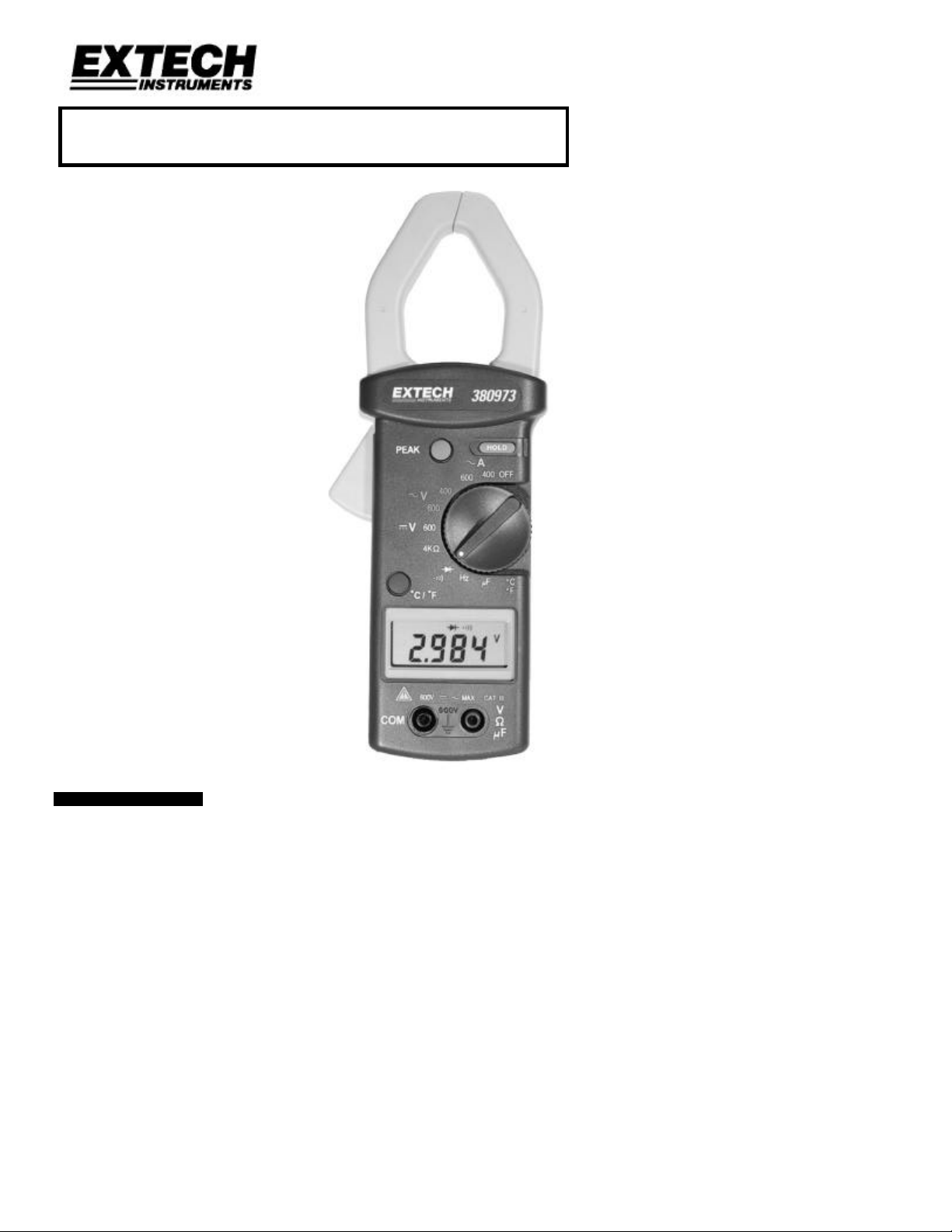
Model 380973
True RMS AC Clamp-on DMM
• True RMS AC measurements enable
precision distorted or non-sinusoidal
waveform measurements
• Peak Hold and Data Hold
• Selectable temperature measurement units
• Frequency measurements using the current
jaws or using the test leads.
1. INTRODUCTION
Congratulations on your purchase of Extech’s 380973 True RMS AC Clamp-on DMM. This
professional meter, with proper care, will provide years of safe reliable service.
1 380973 Ver. 1.01 8 /99
Page 2
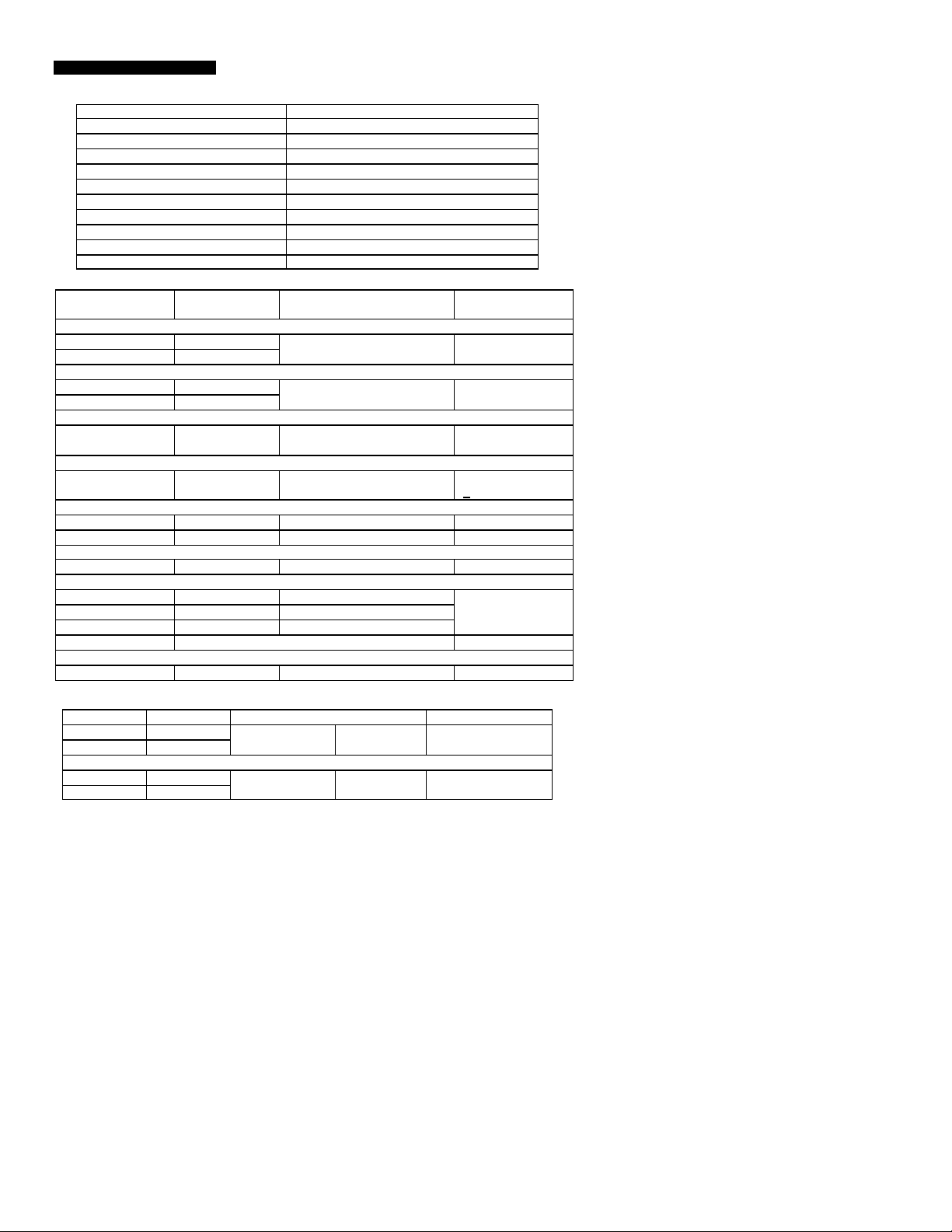
2. SPECIFICATIONS
2.1 General Specifications
Clamp jaw opening diameter 1.6” (40mm)
Battery type 9V
Range Selection Manual
Display 3 ¾ digit (4000 count) LCD
Overload Indication ‘OL’ displays on LCD
Low Battery Indication ‘BT’ displays on LCD
Sampling rate 2.5 readings/sec
Operating Temp. / RH 32 to 104oF (0oC to 40oC); <80%
Storage Temp. / RH 14 to 140oF (-10oC to 60oC); <70%
Dimensions 9 x 3 x 1.5” (228 x 76 x 39mm)
Weight 12.4 oz. (385g)
2.2 Electrical Specifications
Resolution Accuracy
Overload Protect
(% of reading + digits))
AC Current (True RMS)
400A 0.1A
±(2.0% + 5d) (40 to 450Hz) 800A rms
600A 1A
AC Voltage (True RMS)
400V 0.1V
600V 1V
±(1.2% + 5d) (40 to 450Hz) 660V rms
input imp. 1MΩ
DC Voltage
600V 1V ±(0.75% + 2d) 660V rms
input imp. 1MΩ
Resistance
4KΩ 0.001kΩ
±(1.0% + 5d) 660V rms
< 3.2VDC open cir
Frequency
4KHz (clamp test) 1Hz ±(0.5%rdg + 5d) 800A (sensitiv.5A)
4KHz (lead test) 1Hz ±(0.5%rdg + 5d) 660V (sensitiv.1V)
Capacitance
2000uF 1uF ±(3% + 5d) 250V rms
Type-K Therm.
-20 to 300oC 1oC ±(2% + 3oC)
660 Vrms
300 to 1200oC 1oC ±(3.5% + 2oC)
-4 to 2192oF 1oF ±(3% + 8oF)
Continuity Buzzer <40 ohms (oc V=3V, sc A=0.8mA) 660 V rms
Diode Test
3V 0.001V ±(1%rdg + 2d) 660V rms
2.3 100mS PEAK HOLD (True RMS) Specifications
AC Voltage Resolution Accuracy (of reading) Overload
400V 0.1V
±(1.5% + 10d) 50 to 60Hz 660V rms
600V 1V
AC Current
400A 0.1A
±(2.0% + 10d) 50 to 60Hz 800A rms
600A 1A
SPECIFICATION NOTE: Accuracy is tested in a 64 to 82oF (18 to 28oC) <80% Relative
Humidity environment. The accuracy specs apply to measurements taken in the largest
circle inside the clamp jaw (refer to the diagram in Section 3).
2 380973 Ver. 1.01 8 /99
Page 3
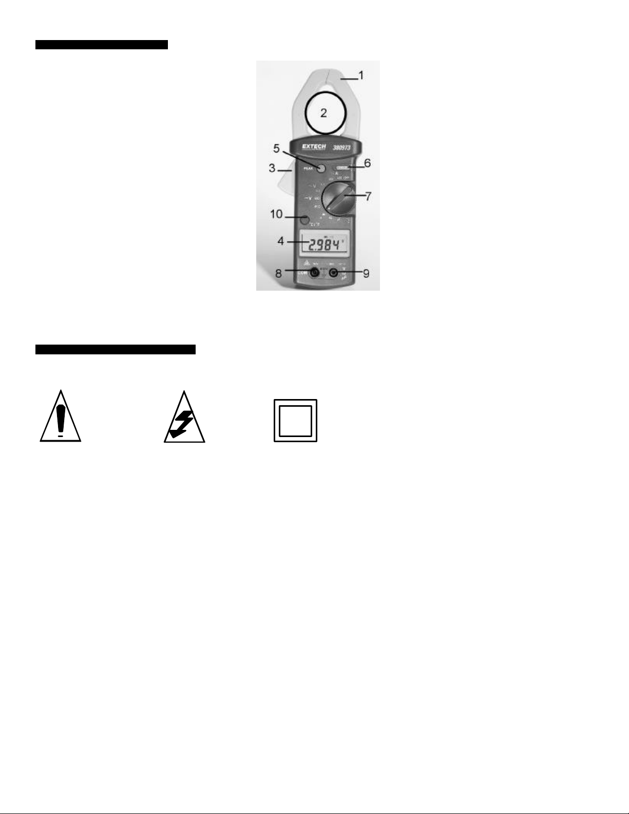
3. FRONT PANEL DESCRIPTION
1 Clamp jaw
2 Clamp measurement area
3 Jaw trigger – Press to open transformer jaw
4 LCD Display – Displays data, units, polarity,
decimal, peak/data hold icons, overload and low
battery indication.
5 Peak Hold key – Press to activate, press again to
deactivate.
6 Data Hold key - Press to activate, press again to
deactivate.
7 Rotary selector switch – Powers meter while
selecting function and range.
8 Negative input terminal – Black test lead
connection (COM).
9 Positive input terminal – Red test lead connection
for voltage, resistance, frequency, capacitance,
temperature, diode, and continuity tests.
10 Temperature units select key – Press to select
desired units
4. INTERNATIONAL SAFETY SYMBOLS
CAUTION:
Refer to
documentation
CAUTION:
Risk of
Electrical
Double
Insulation
Shock
3 380973 Ver. 1.01 8 /99
Page 4

5. OPERATION
5.1 True RMS Measurements
The 380973 incorporates True RMS technology meaning that non-sinusoidal (triangle,
sawtooth, etc.) or distorted waveforms can be measured more accurately than averaging
meters. The degree of distortion that the meter can accurately measure is determined by
the ‘crest factor’ of a waveform (ratio of peak value to rms value).
5.2 Measurement Preparation
1. Use the Rotary Selector switch (7) to select the appropriate range and function. Ensure
that the selected range is suitable for the measurement to be taken.
2. If the measured current is higher than the selected range for long periods of time,
overheating can result which may damage the meter.
3. Do not measure current on high voltage conductors (> 600V).
5.3 AC Current Measurements
WARNING: Ensure that all test leads are disconnected
from the meter’s terminals before proceeding.
1. Set the Rotary Selector switch to the 400 or 600 Amps
AC (~) range.
2. Clamp the transformer jaw around one of the
conductors under test. Open the jaw via the jaw trigger
(3). Ensure that the clamp closes completely around
the conductor.
3. Read the displayed measurement value on the display.
5.4 DC Voltage Measurements
Warning: Maximum DC input voltage is 600V. To avoid
electrical shock or damage to the instrument, do not attempt
to measure any voltage exceeding this limit.
1. Set the Rotary Selector switch to the 600Volts DC (----)
range.
2. Connect the black test lead to the COM terminal and red
test lead to the V/Ω/uF terminal.
3. Connect the test leads to the circuit, component, or other
device under test (refer to figure at right).
4. Read the displayed measurement value on the LCD.
5.5 AC Voltage Measurements
Warning: Maximum AC input voltage is 600V. To avoid
electrical shock or damage to the instrument, do not attempt
to measure any voltage exceeding this limit.
1. Set the Rotary Selector switch to the AC Volts (~) range.
2. Connect the black test lead to the COM terminal and red
test lead to the V/Ω/uF terminal.
3. Connect the test leads to the circuit, component, or other
device under test (refer to figure at right).
4. Read the displayed measurement value on the LCD.
4 380973 Ver. 1.01 8 /99
Page 5

5.6 Frequency Measurements
Note: Clamp (ammeter) and test lead (voltage) frequency measurements can both be
made. Check the specifications for differences in sensitivity. When reading frequency via
the clamp jaw the current must be at least 5A (minimum threshold).
1. Set the Rotary Selector switch to the Hz function.
2. Connect the black test lead to the COM terminal and red test lead to the V/Ω/uF terminal
and connect the other ends of the test leads to the circuit, component, or other device
under test for test lead measurements; otherwise use the clamp jaw for current
measurements.
3. Read the displayed measurement value on the LCD.
5.7 Resistance Measurements
Warning: Before attempting any in-circuit resistance measurements remove power from
the circuit under test and discharge any capacitors.
1. Set the Rotary Selector switch to the Ω function.
2. Connect the black test lead to the COM terminal and red test lead to the V/Ω/uF terminal
and connect the other ends of the test leads to the circuit, component, or other device
under test.
3. Read the displayed measurement value on the LCD.
5.8 Capacitance Measurements
Warning: Discharge capacitors and circuit before testing.
1. Set the Rotary Selector switch to the uF function.
2. Remove at least one leg of a capacitor from its circuit before testing.
3. Connect the black test lead to the COM terminal and red test lead to the V/Ω/uF terminal
and connect the other ends of the test leads to the circuit, component, or other device
under test.
4. If measuring a polarity sensitive electrolytic capacitor, touch red test lead to the positive
side of the cap. and the black test lead to the negative side.
5. Read the displayed measurement value on the LCD.
5.9 Temperature Measurements
1. Set the Rotary Selector switch to the “C / F” function.
2. Set the temperature units with the temperature units key.
3. Insert the type-K thermocouple adapter into the meter (positive end to the V/Ω/uF meter
terminal).
4. Insert the thermocouple into the thermocouple adapter.
5. Secure the beaded end of the K-type thermocouple to the surface to be measured.
6. Read the displayed temperature value on the LCD.
5.10 Continuity Measurements
Warning: Before attempting any in-circuit measurements remove power from the circuit
under test and discharge any capacitors.
1. Set the Rotary Selector switch to the diode/continuity function (diode symbol).
2. Connect the black test lead to the COM terminal and red test lead to the V/Ω/uF
terminal and connect the other ends of the test leads to the circuit, component, or other
device under test.
3. When the resistance measured is lower than 40Ω, the meter will sound an audible tone.
5 380973 Ver. 1.01 8 /99
Page 6

5.11 Diode Measurements
Warning: Before attempting any in-circuit measurements remove power from the circuit
under test and discharge any capacitors.
1. Set the Rotary Selector switch to the diode/continuity function (diode symbol).
2. Connect the black test lead to the COM terminal and red test lead to the V/Ω/uF
terminal.
3. Connect the red test lead to the anode side of the diode, and the black test lead to the
cathode side of the diode under test.
4. Read the forward voltage value on the LCD.
5. If the test leads are connected in reverse of step 3 above, the meter should read open
circuit voltage if the diode is in working condition.
5.12 Peak Hold / Data Hold Modes
1. Peak Hold allows the meter to capture fast voltage or current peaks.
2. Data Hold freezes the reading on the display when the Data Hold key is pressed.
3. Set the Rotary Selector switch to the AC Voltage or Current function position for Peak
Hold measurements. For Data Hold, set the switch to any function position.
4. Set the clamp meter to the Peak Hold or Data Hold mode by pressing the Peak Hold or
Data Hold key once.
5. The display will now indicate “P” for Peak Hold or ‘H’ for Data Hold.
6. For Peak Hold, the display will show the maximum peak of a measured signal surge. For
example, in-rush current during a motor start-up can be easily detected using Peak Hold
mode. For Data Hold, the LCD reading is frozen.
7. To return to normal operation press the Peak or Data Hold key again.
6. MAINTENANCE
6.1 Battery Replacement
Warning: To prevent electrical shock or hazard, remove power to the meter and remove
the test leads before removing back cover.
1. The meter displays ‘BT’ when the battery voltage falls critically low. Replace battery as
soon as possible when this icon appears on the meter LCD.
2. Set the rotary switch to the OFF position and remove all test leads.
3. Unscrew the three back cover screws to access the battery compartment. Note that the
screw nearest the meter jaw is a shorter machined screw. Be sure to install the same
screws in the same screw holes after replacing battery.
4. Replace battery and reinstall back cover.
6.2 Cleaning
Warning: To avoid electrical shock or damage to the meter, do not allow water or other
liquids to enter the meter case. Remember to remove power and test leads before
opening meter case.
Periodically wipe the case with a damp cloth and mild detergent. Do not use abrasives or
solvents.
6 380973 Ver. 1.01 8 /99
Page 7

7. CALIBRATION / REPAIR SERVICES
Extech offers complete repair and calibration services for all of the products we sell. For
periodic calibration, NIST certification or repair of any Extech product, call customer
service for details on services available. Extech recommends that calibration be performed
on an annual basis to insure calibration integrity.
8. WARRANTY
EXTECH INSTRUMENTS CORPORATION warrants this instrument to be free of defects in parts and
workmanship for one year from date of shipment (a six month limited warranty applies on sensors and
cables). If it should become necessary to return the instrument for service during or beyond the warranty
period, contact the Customer Service Department at (781) 890-7440 for authorization. A Return
Authorization (RA) number must be issued before any product is returned to Extech. The sender is
responsible for shipping charges, freight, insurance and proper packaging to prevent damage in transit.
This warranty does not apply to defects resulting from action of the user such as misuse, improper wiring,
operation outside of specification, improper maintenance or repair, or unauthorized modification. Extech
specifically disclaims any implied warranties or merchantability or fitness for a specific purpose and will not
be liable for any direct, indirect, incidental or consequential damages. Extech's total liability is limited to
repair or replacement of the product.
The warranty set forth above is inclusive and no other warranty, whether written or oral, is expressed or
implied.
Copyright © 1999 Extech Instruments Corporation. All rights reserved including the
right of reproduction in whole or in part in any form.
7 380973 Ver. 1.01 8 /99
 Loading...