

Page 1
INSTRUCTION MANUAL
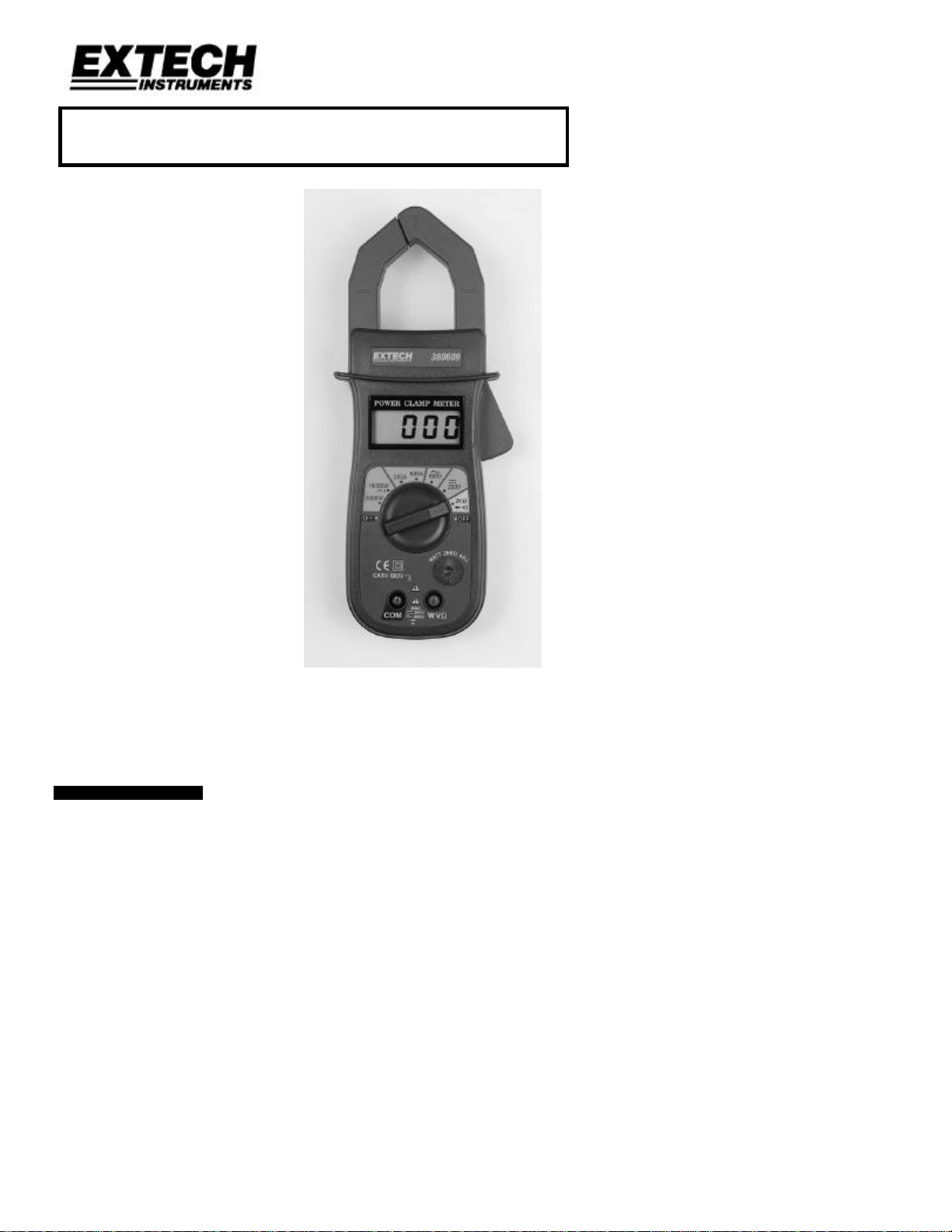
Model 380609
AC Clamp Watt Meter
• Measure Watts, ACV, DCV, ACA,
Ohms, Diode
• Large 3 ½ digit LCD
• Zero adjustment for Watt readings
• AC current to 600A
• AC power to 10000 Watts
1. INTRODUCTION
Congratulations on your purchase of Extech’s Watt Clamp Meter. This professional meter,
with proper care, will provide years of safe reliable service.
1 380609 Ver. 1.00 1/99
Page 2
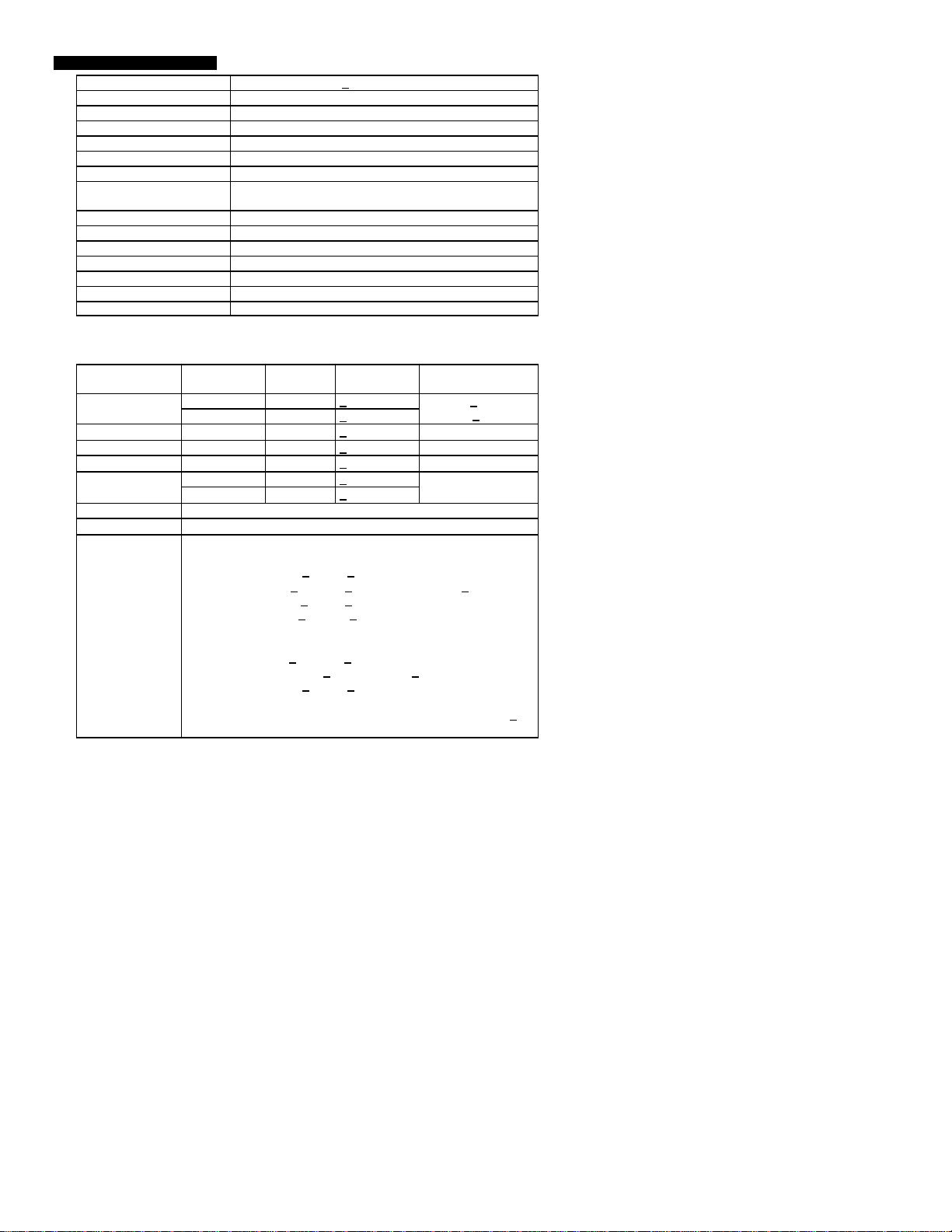
2. SPECIFICATIONS
Display 3 ½ Digit 0.5” LCD (+1999 count)
Functions Watts, DCV, ACV, ACA, Ohms, Diode
Polarity “-“ indicates negative polarity
Current sensor Hall effect sensors
Overload Display indicates “1” or “-1”
Watt zero adjustment Built-in adjustment knob
Display rate Approximately 0.4 seconds
Battery Heavy duty or alkaline 9VDC (006P, MN1604 or
equivalent)
Operating temperature 320F to 1220F (00C to 500C)
Operating Humidity < 80% RH
Power consumption Approximately 15mA DC
Weight 1lb (450gm) including battery
Dimensions 9.1 x 2.9 x 1.5” (230 x 74 x 38mm) (HWD)
Jaw opening 1.5” (38mm)
Standards IEC 1010 Category III 600V
Function (model) Measurement
Range
2,000 Watts 1 Watt +(2.5%+8d) AC Watts
(true power)
10,000 Watts 10 Watts +(3%+8d)
Resolution Accuracy
FS. + digits
Voltage < 600VAC
Current: < 50ACA
DC Voltage 200V 0.1V +(0.8%+1d) 600VDC
AC Voltage 600V 1V +(1%+2d) 600VAC
Ohms
2kΩ 1Ω
200A 0.1A +(2%+10d) AC Current
+(1%+1d) 250VAC & VDC
1000ACA
600A 1A +(2%+5d)
Diode 2.8V open circuit
Continuity
Notes:
Beeper sounds if the resistance is less than 50Ω
ACV and DCV input impedance: 10MΩ
Watt measurement allowable input signal:
1) Power factor: > 0.5 to < 1.0
2) AC Current: > 0.5A to < 30A when ACV is < 250V
> 2A to < 30A when ACV is > 250V
3) ACV must be > 20V to < 500V
4) Frequency range: 45Hz to 65Hz
Watt accuracy is specified under the following conditions:
1) AC current: > 3.0A to < 30A
2) AC voltage: 110V + 15% or 220V + 15%
3) Power factor: > 0.8 to < 1.0
4) Frequency: 50Hz or 60Hz
ACA and ACV specifications stated at 50/60Hz and 23oC + 5oC
ACA and ACV frequency response: 40Hz to 400Hz
Overload
Protection
2 380609 Ver. 1.00 1/99
Page 3

3. FRONT PANEL DESCRIPTION
1 Current sense jaw
2 LCD display
3 Trigger
4 Function switch
5 Watt zero adjust
6 Input terminals
7 Battery cover (rear)
4. PREPERATION FOR MEASUREMENT
1. Ensure that the battery is correctly connected and secured in the battery
compartment.
2. Insert the RED test lead into the WVΩ jack and the BLACK test lead into the COM
jack for watt, voltage or resistance measurements.
3. Disconnect the test leads from the test circuit when changing ranges or function.
4. Do not exceed the maximum rated voltage to the input terminals.
5. Always set the Function switch to the OFF position when the meter is not in use.
6. Remove the battery if the meter is not to be used for a long period of time.
7. Make sure no voltage is applied to the circuit under test when using the Ohm or
Continuity function.
4.1 International Symbols
3 380609 Ver. 1.00 1/99
Page 4

5. OPERATION
5.1 AC Current Measurements
1) Rotate the Function switch to the 200A or 600A range. If the value of the current
to be measured is unknown, set the switch to the highest range.
2) Press the jaw trigger and clamp around a single conductor.
3) Read the ACA value on the LCD display.
5.2 AC Voltage measurements
1) Connect the red test lead into the “V” input terminal and the black test lead into
the “COM” input terminal.
2) Rotate the Function switch to the “AC 600V” position.
3) Connect the test leads to the circuit under test and read the value on the LCD
display.
4) Do not exceed 600V AC.
5.3 DC Voltage measurements
1) Connect the red test lead into the “V” input terminal and the black test lead into
the “COM” input terminal.
2) Rotate the Function switch to the “DC 200V” position.
3) Connect the test leads to the circuit under test and read the value on the LCD
display.
4) Do not exceed 200V DC.
5.4 Resistance measurements
1) Connect the red test lead into the “Ω” input terminal and the black test lead into
the “COM” input terminal.
2) Rotate the Function switch to the “2k ohm” position.
3) Remove any power to the circuit under test and discharge any capacitors.
4) Connect the test leads to the circuit under test and read the value on the LCD
display. If the resistance is less than 50Ω, the continuity beeper will sound.
5) Do not exceed 600V AC.
5.5 Watt (power) measurements
1) Rotate the Function switch to the “2,000W” or the “10,000W” position.
2) Adjust the “Watt Zero” adjust until the display indicates zero.
3) Connect the test leads as described in the AC Voltage paragraph.
4) Connect the jaw as described in the AC current paragraph.
5) The LCD display will indicate the AC Watt value (true power)
NOTE: Observe the voltage and current limitations stated in the specifications.
NOTE: On the 10000 Watt range, the displayed reading must be multiplied by 10
(i.e. A reading of 600 = 6000 watts).
5.6 Continuity Beeper
1) Connect the red test lead into the “Ω” input terminal and the black test lead into
the “COM” input terminal.
2) Rotate the Function switch to the “ ” position.
3) Remove any power to the circuit under test and discharge any capacitors.
4) If the resistance is less than 50Ω, the continuity beeper will sound.
4 380609 Ver. 1.00 1/99
Page 5

5.7 Diode Test
1) Connect the red test lead into the “V/Ω” input terminal and the black test lead into
the “COM” input terminal.
2) Rotate the Function switch to the “ ” position.
3) Remove any power to the circuit under test and discharge any capacitors.
4) Connect the test leads to the circuit under test.
5) When connected in the forward direction the diode forward voltage will be
displayed. For short circuits, a near zero reading will be displayed and for open
circuits, a "1" will be displayed. Reverse connections will display near ".000" for a
good diode and "1" for a bad diode
6. MAINTENANCE
6.1 Battery Replacement
Note: Remove the test leads before replacing the battery
1) When “LOBAT” appears in the lower left-hand area of the display the battery
should be replaced.
2) Open the rear battery cover using a flat tipped screwdriver or a coin.
3) Replace the 9volt battery and reinstall the cover.
6.2 Cleaning
Caution: Use only a dry cloth to clean the plastic case.
7. CALIBRATION / REPAIR SERVICES
Extech offers complete repair and calibration services for all of the products we sell. For
periodic calibration, NIST certification or repair of any Extech product, call customer
service for details on services available. Extech recommends that calibration be performed
on an annual basis to insure calibration integrity.
8. WARRANTY
EXTECH INSTRUMENTS CORPORATION warrants this instrument to be free of defects in parts and
workmanship for one year from date of shipment (a six month limited warranty applies on sensors and
cables). If it should become necessary to return the instrument for service during or beyond the warranty
period, contact the Customer Service Department at (781) 890-7440 for authorization. A Return
Authorization (RA) number must be issued before any product is returned to Extech. The sender is
responsible for shipping charges, freight, insurance and proper packaging to prevent damage in transit.
This warranty does not apply to defects resulting from action of the user such as misuse, improper wiring,
operation outside of specification, improper maintenance or repair, or unauthorized modification. Extech
specifically disclaims any implied warranties or merchantability or fitness for a specific purpose and will not
be liable for any direct, indirect, incidental or consequential damages. Extech's total liability is limited to
repair or replacement of the product.
The warranty set forth above is inclusive and no other warranty, whether written or oral, is expressed or
implied.
Copyright © 1999 Extech Instruments Corporation. All rights reserved including the
right of reproduction in whole or in part in any form.
5 380609 Ver. 1.00 1/99
 Loading...