

Page 1
User Guide
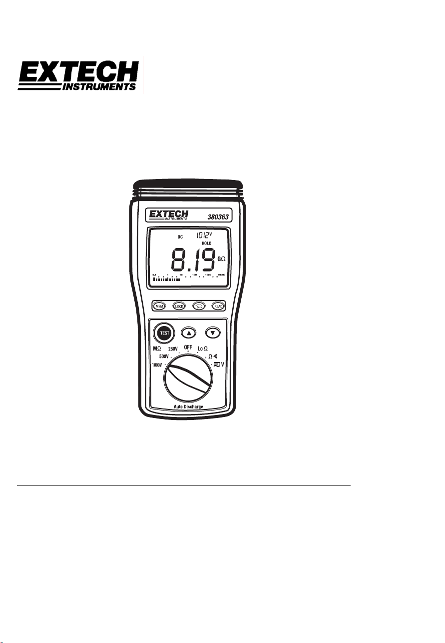
Model 380363
Insulation Tester / Megohmmeter
Introduction
Congratulations on your purchase of Extech’s Insulation Tester/Megohmmeter. The Model
380363 provides three test ranges plus continuity and AC/DC voltage measurement. Manual
datalogging stores up to 9 data sets. This professional meter, with proper care, will provide
years of reliable service.
Page 2
Safety
1. Circuits under test must be de-energized and isolated before connections are made
(except for voltage measurements).
2. Circuit connections must not be touched during a test. Use extreme caution when
working near bare conductors and bus bars. Accidental contact with conductors could
result in electrical shock.
3. Use caution when working near voltages above 60VDC or 30VACrms.
4. After insulation tests, capacitors must be discharged.
5. Test leads (including alligator clips) must be in good working order, clean and without
broken or cracked insulation.
6. When servicing, use only specified replacement parts.
International Safety Symbols
Caution, refer to this manual before using this meter
Dangerous Voltages
Meter is protected throughout by double or reinforced insulation
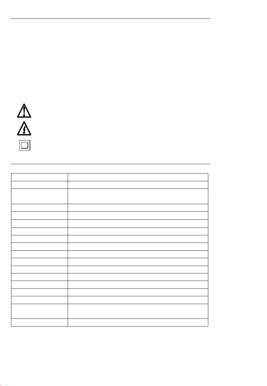
Specifications
General specifications
Display 3-3/4 digit (4000 count) LCD
Sampling rate 1 reading per second
Test ranges
AC/DC Voltage range 999V
Resistance range
Lo Resistance range
Over range indicator ‘OL’ displayed when measurement exceeds range
Zero adjust Automatic
Memory Nine (9) data records
Low battery indicator ‘BT’ symbol displayed when battery voltage is low
Power source Six (6) 1.5 ‘AA’ batteries
Power consumption 20 to 95mA (depending upon function)
Fuse protection 0.5A / 600V fast blow fuse
Operating conditions 32 to 122oF (0 to 50oC); 80% RH
Dimensions 9.3 x 4.6 x 2.1” (235 x 116 x 54mm)
Weight 1.15 lbs (520g)
Safety ratings Pollution degree 2; indoor use; CE marked;
Category Rating CAT III-1000V
Resistance: 4MΩ, 40MΩ, 400MΩ, 4000MΩ, 10GΩ
Test Voltages: 250V, 500V, 1000V
9999Ω
40Ω
Meets IEC 61010-1 and IEC 61557 standards
2
Model 380363 Version 2.0 July 2005
Page 3
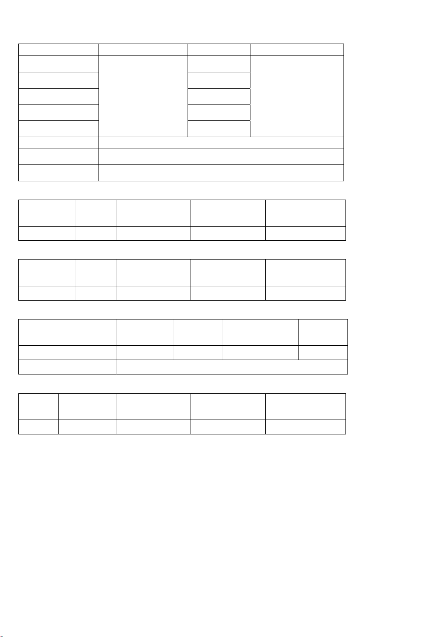
Range Specifications
MEGOHMMETER RANGES
Range Test Voltages Resolution Accuracy
4MΩ 0.001MΩ
40MΩ 0.01MΩ
400MΩ 0.1MΩ
4000MΩ 1MΩ
10GΩ
250V (+30% ~ -0%)
500V (+30% ~ -0%)
1000V (+30% ~ -0%)
00.01GΩ
3%+5 (<1000M)
5%+5 (>1000M)
(% reading + digits at
o
23
C ± 5oC < 80% RH)
Analog Bar Graph 0 to 10G
Nominal Current
Circuit Protection
≧ 1mA
Test inhibited if input ≧ 30V AC or DC
AC VOLTAGE (40Hz-500Hz)
Range Res. Accuracy Input impedance Overload
Protection
999VAC 1V ±2% + 2d
9MΩ
1000Vrms
DC VOLTAGE
Range Res. Accuracy Input impedance Overload
Protection
999VDC 1V ±1% + 2d
9MΩ
1000Vrms
RESISTANCE & CONTINUITY
Range Res. Accuracy Max. open circuit
Resistance: 999.9Ω 0.1Ω
Continuity
±1% + 3d 3V 1000Vrms
100Ω ± 80Ω)
Volt
Overload
Protect.
LOW RESISTANCE Ω
Range Res. Accuracy Max. open
circuit Volt
40Ω 0.01Ω
±2% + 2d 6V >30V AC/DC
Overload
Protection
3
Model 380363 Version 2.0 July 2005
Page 4

Meter Description
1. LCD Display
2. LOCK button
3. MEMORY control button
4. UP arrow key
5. TEST button
6. Rotary switch
7. DOWN arrow key
8. READ memory button
9. ZERO adjust button
10. Input terminals
The tilt stand and battery compartment are
located at the rear of the instrument
1
2
3
4
5
6
Warning
Ensure that the circuit under test does not include components that can be damaged by 1000VDC; such
devices include power factor correction capacitors, low voltage mineral insulated cables, electronic light
dimmers, and ballasts/starters for fluorescent lamps.
10
9
8
7
Operation
Connecting Test Leads
For all measurements connect the red test lead to the VΩ input terminal and the black test
lead to the COM input terminal.
Test Lead Check
1. Set the rotary switch to the Ω range.
2. Touch the test lead tips together.
3. Resistance should read less than 0.5Ω and the audio tone should sound.
4. With the leads not touching, the display should read OL indicating over-range.
5. Readings displayed other than the readings described above are evidence of a
problem and the test leads must be replaced before using the meter. Failure to do so
could result in damage to equipment and electrical shock. If replacing the test leads
does not solve the problem, return the instrument for repair.
4
Model 380363 Version 2.0 July 2005
Page 5

Insulation Resistance Measurements (Megohmmeter Tests)
Warning: Do not perform Insulation Resistance measurements if AC Voltage is present on the
device under test.
1. Connect the red test lead to the VΩ input terminal; black lead to the COM terminal.
2. Set the function switch to the desired MΩ test voltage position.
3. Connect the tips of the test leads to the equipment under test. If there is a voltage
present, it will be displayed. A repetitive beep and the flashing high voltage symbol
will be displayed if the voltage is over 30V.
4. The display will show “----“ until the TEST button is pushed. Press and hold the TEST
button. The upper right display shows the test voltage applied. The main display
shows the resistance. If the display reads OL, the measurement is beyond the range
of the instrument.
5. Keep the test leads connected to the equipment under test and release the TEST
button. The circuit will discharge through the meter. Keep the test leads connected
until the circuit is completely discharged and the upper right display shows 0 volts.
Test Lock Function
For hands-free operation, use the TEST LOCK feature.
1. With the test leads connected to the equipment under test, press the LOCK key to
enter the LOCK mode. The LOCK icon “ “ will appear on the display.
2. Press the TEST key to start the test. A beeper will sound every 2 seconds to indicate
that the meter is in Lock mode.
3. Press LOCK or TEST to disable the Lock function and end the test.
Notes on IR (Megohmeter) testing:
1. The maximum measurement range for the 380363 is 10G. Frequently, insulation
resistance will exceed this value and the meter will show the overload display
symbol OL, indicating that the insulation under test is good.
2. If the device being tested is highly capacitive, the display will indicate an increasing
resistance value over time. Allow the reading to stabilize before ending a test.
Manual Data Store and Read Mode
To Clear Memory
1. Turn the meter off.
2. Press and hold down the MEM key, and turn the meter on.
3. The display will show “MEM0” in the upper left hand corner - indicating that the
memory has been erased.
Entering data into memory
1. Press the MEM key to enter the displayed data into memory (a beep will sound).
2. The display will show “MEM” and the memory address number in the upper left
hand corner. Total memory size is 9 sets.
3. When memory is full, the meter will sound two quick beeps.
Reading memory data
1. Press the READ key to enter Read Mode. The display will show the “READ” icon
and the memory address number in the upper left hand corner.
2. Use the and arrow keys to scroll through the stored readings.
3. Press the READ key again to exit this mode.
5
Model 380363 Version 2.0 July 2005
Page 6

AC/DC Voltage Measurement
1. Set the Rotary switch to the ~V position.
2. Connect the red test lead to the VΩ terminal and the black test lead to the COM
terminal.
3. Connect the test leads to the circuit under test.
4. Read the voltage value on the LCD. The meter shows DC voltage in the upper right
and AC voltage on the main display.
Resistance Measurement and Audible Continuity Test
Do not run this test unless ACV = 0. Do not use this mode to check diodes.
1. Set the Rotary switch to the Ω position.
2. Connect the red test lead to the VΩ terminal and the black lead to the COM terminal.
3. Connect the tips of the test leads to the circuit under test.
4. Read the resistance value on the display. When the resistance of a circuit is less than
approx. 100Ω ± 80Ω, the audible tone will sound.
WARNING
LOΩ Low Resistance Measurement
1. Set the Rotary switch to the Lo position.
2. Connect the red test lead to the VΩ terminal and the black lead to the COM terminal.
3. Touch the test leads together and press the
4. Connect the probes to the ciruit under test. If there is a voltage present, it will be
displayed. A repetitive beep and the flashing high voltage symbol will be displayed if
the voltage is over 30V. Remove the voltage before proceeding to the next step.
5. Press and hold the TEST key until a stable reading is displayed.
6. Release the TEST key. The upper right hand display will hold the reading until a new
test is started or a different function is selected.
7. Swap the red and black probes to reverse the polarity of the test current. The reading
should remain the same. This test is useful to detect corroded connections which can
cause different readings in both polarities.
6
key to zero the display.
Model 380363 Version 2.0 July 2005
Page 7

Using the LOCK Function to measure resistance
The Lock function can be used to make several resistance measurements in succession
without the need to push and hold the TEST key for each measurement.
1. Press the LOCK key to enter the LOCK mode, and then press the TEST key.
2. Zero out the test lead resistance.
3. Connect the probes to the test locations in succession.
4. Press the LOCK key to disable the lock function.
Note: The meter cannot indicate if the circuit is live in this mode. Ensure that the circuit is deenergized before connecting the test leads or the fuse may blow.
Auto Power Off
To conserve battery life, the meter will automatically turn off after 15 minutes of non-use.
To turn the meter back on, turn the rotary switch to OFF, then to the desired function.
Analog Bar Graph
The analog bar graph displays resistance on a logarithmic scale and voltage on a linear
scale. The value always tracks the main display.
Maintenance
Battery Replacement
When the low battery symbol appears (BT) on the LCD the six 1.5V ‘AA’ batteries must be
replaced.
1. Turn the meter off and remove the test leads
2. Remove the four (4) Phillips head screws on the rear of the meter
3. Remove the meter’s rear cover
4. Replace the batteries observing polarity
5. Affix the rear cover and secure the rear screws
Fuse Replacement
If the meter turns ON but does not measure correctly, check the internal fuse.
1. Turn the meter off and remove the test leads
2. Remove the four (4) Phillips head screws on the rear of the meter
3. Remove the meter’s rear cover
4. Check and replace the fuse if necessary (0.5A / 600V fast blow)
5. Affix the rear cover and secure the rear screws
Cleaning
Periodically wipe the case with a dry cloth. Do not use solvents or abrasives to clean this
instrument.
7
Model 380363 Version 2.0 July 2005
Page 8

Applications
Measuring Power Tools and Small Appliances
This section applies to any device under test that uses a
line cord. For double insulated power tools, the meter’s
leads should be connected to the device’s housing (chuck,
blade, etc.) and to the lines of the power cord. Refer to the
diagram.
Testing AC Motors
Disconnect the motor from the line by disconnecting the wires from the motor terminals or
opening the mains switch.
If the mains switch is opened, and the motor also has a motor-starter, then the starter must
be held in the ON position. With the mains switch opened, the measured resistance will
include the resistance of the motor wire and all other components between the motor and
the main switch. If a weakness is indicated, the motor and other components should be
checked individually. If the motor is disconnected at the motor terminals, connect one
meter lead to the grounded motor housing and the other lead to one of the motor leads.
Refer to diagram at below.
Motor
Starter
GND
Mains
Switch
Notes:
1. The STARTER must be in the ON position during the
8
Line
Model 380363 Version 2.0 July 2005
Page 9

Testing DC Motors
1. Disconnect the motor from the line.
2. To test the brush rigging, field coils and armature, connect one meter lead to the
grounded motor housing and the other lead to the brush on the commutator.
3. If the resistance measurement indicates a weakness, raise the brushes off of the
commutator and separately test the armature, field coils and brush rigging (one at a
time). Leave one lead connected to the grounded motor housing while testing the
motor components. This also applies to DC Generators.
Testing Cables
1. Disconnect the cable under test from the line.
2. Disconnect the opposite end of the cable to avoid errors as a result of leakage from
other equipment.
3. Check each conductor to ground and/or lead sheath by connecting one meter lead to
ground and/or lead sheath and the other meter lead to each of the conductors in turn.
4. Check insulation resistance between conductors by connecting meter leads to
conductors in pairs. Refer to diagram. In the diagram, note that the 3-conductor cable
has two wires shorted to the ground shield. This two-wire/shield connection is then
connected to one side of the meter. The remaining conductor is connected to the
other side of the meter.
9
Model 380363 Version 2.0 July 2005
Page 10

Repair and Calibration
Extech offers repair and calibration services for the products we sell. Extech also provides
NIST certification for most products. Call the Customer Service Department for information
on calibration services available for this product. Extech recommends that annual
calibrations be performed to verify meter performance and accuracy.
Technical support: Extension 200; E-mail: support@extech.com
Repair & Returns: Extension 210; E-mail: repair@extech.com
Product specifications subject to change without notice
For the latest version of this User’s Guide, Software updates, and other
up-to-the-minute product information, visit our website: www.extech.com
Support line (781) 890-7440
Warranty
EXTECH INSTRUMENTS CORPORATION warrants this instrument to be free of defects in parts and
workmanship for one year from date of shipment (a six month limited warranty applies on sensors and
cables). If it should become necessary to return the instrument for service during or beyond the warranty
period, contact the Customer Service Department at (781) 890-7440 ext. 210 for authorization or visit our
website at www.extech.com (click on ‘Contact Extech’ and go to ‘Service Department’ to request an RA
number). A Return Authorization (RA) number must be issued before any product is returned to Extech. The
sender is responsible for shipping charges, freight, insurance and proper packaging to prevent damage in
transit. This warranty does not apply to defects resulting from action of the user such as misuse, improper
wiring, operation outside of specification, improper maintenance or repair, or unauthorized modification.
Extech specifically disclaims any implied warranties or merchantability or fitness for a specific purpose and
will not be liable for any direct, indirect, incidental or consequential damages. Extech's total liability is limited
to repair or replacement of the product. The warranty set forth above is inclusive and no other warranty,
whether written or oral, is expressed or implied.
Copyright © 2005 Extech Instruments Corporation.
All rights reserved including the right of reproduction in whole or in part in any form.
10
Model 380363 Version 2.0 July 2005
 Loading...