

Page 1
User's Guide
Oyster Meter
pH-Conductivity-TDS-Salinity-ORP(mV)
Model 341350A
Page 2
INTRODUCTION
Congratulations on your purchase of the Extech's Oyster Series meter. This device measures
pH, Conductivity, TDS, ORP and Salinity. These meters are intended for routine laboratory
and field testing. Accurate measurements are provided in a battery operated, portable meter
with a hinged display that can be adjusted to any viewing angle.
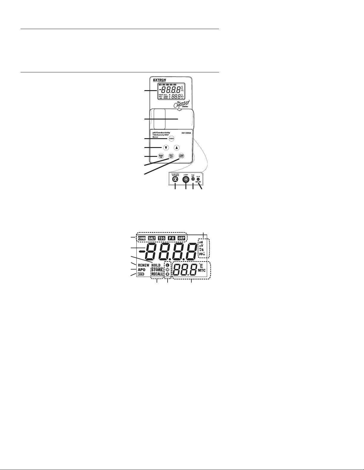
METER DESCRIPTION
Front and Side panels
1. LCD display
2. Battery compartment
3. Power button
4. Up/Down arrow buttons
5. MODE/CAL button
6. UNIT/SET button
7. STORE/RECALL button
8. Connector, Conductivity probe
9. Connector, pH probe
10. Connector, Temperature probe
11. Connector, AC adapter
Display
1. Mode indicators
2. Primary display
3. Data held indicator
4. Probe renew indicator
5. Auto Power Off indicator
6. Low battery indicator
7. Memory status indicators
8. Calibration status indicators
9. Temperature display
10. Unit indicators
1
2
3
4
5
6
7
891011
10
1
2
3
4
5
6
7
89
2
341350A V1.1 1/09
Page 3
OPERATING INSTRUCTIONS
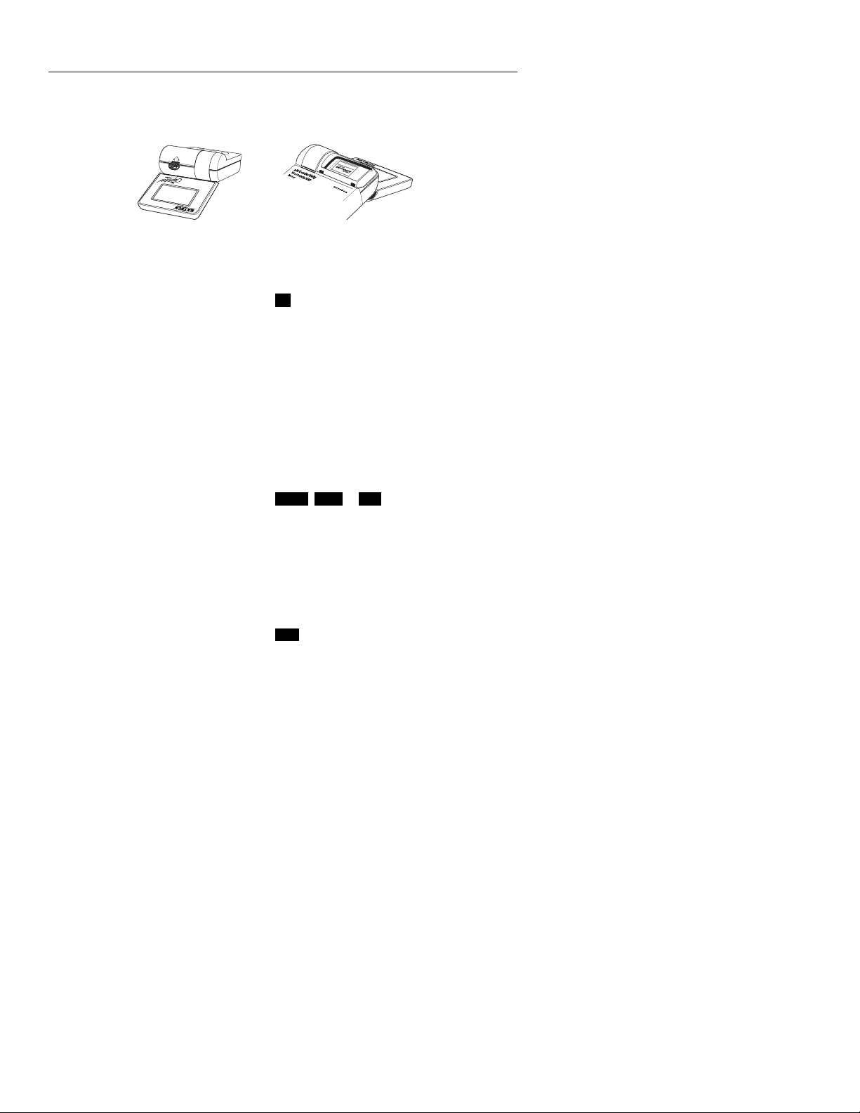
Battery Installation/Replacement
Open the battery cover by inserting a small coin into the latch slot and pressing downward.
The cover will release in the direction of the arrow. Install the new battery and replace the
cover.
pH Measurements
1. Press the POWER button to turn the meter on. (the meter will cycle through a self
check)
2. Press the MODE/CAL button until the PH icon is on.
3. Press the UNIT/SET button to select ºC or ºF.
4. Connect the pH electrode to the side pH BNC connector.
5. Adjust the ▲▼buttons to the temperature of the solution (or use the external
temperature probe).
6. If required, calibrate the electrode. (see pH Calibration)
7. Place the electrode in the sample solution and read the pH value on the display.
8. When all measurements have been taken, unplug the electrode and rinse in distilled
water, shake and store in the wetting cap or a pH 4 buffer solution.
Conductivity/TDS/Salt Measurements
1. Press the POWER button to turn the meter on.
2. Press the MODE/CAL button until the COND, SALT or TDS icon is on.
3. Connect the conductivity electrode to the side conductivity connector.
4. If required, calibrate the electrode. (see Conductivity Calibration)
5. Place the electrode in the sample solution and read the value on the display.
6. When finished, unplug the electrode and rinse in distilled water.
ORP (mV) Measurements
1. Press the POWER button to turn the meter on.
2. Press the MODE/CAL button until the ORP icon is on.
3. Connect the ORP electrode to the side ORP BNC connector.
4. Place the electrode in the sample solution and read the mV value on the display.
5. When all measurements have been taken, unplug the electrode and rinse in distilled
water.
3
341350A V1.1 1/09
Page 4

Data Memory
25 readings can be stored to and recalled from the internal memory.
Storing readings
1. With the reading on the display, momentarily press the STORE/RECALL button. The
STORE and HOLD display icons will appear on the LCD and the reading will freeze.
2. Momentarily press the STORE/RECALL button again to confirm and return to the
normal operation mode.
3. Up to 25 readings can be stored in this fashion.
Recalling Readings
1. Press and hold the STORE/RECALL button. The RECALL icon and the memory
location number will appear followed by the data in the displayed memory location. .
2. Press the ▼or ▲button to scroll through the memory locations and to view the stored
data.
3. Momentarily press the STORE/RECALL button to exit the Recall Readings mode.
End will appear in the display and then the meter will return to the normal
measurement mode.
Clearing the memory
With the meter on, press and hold the ▼ and ▲ buttons for 2 seconds. CLr will appear on
the display indicating that the memory has been erased.
Temperature Units
Press the UNIT button to switch between a ºF or ºC display.
Manual Temperature Compensation
In the pH mode, the solution temperature can be set by using the optional external
temperature probe or by adjusting the temperature display when the probe is not used.
Press the ▲▼buttons to set the temperature when MTC icon is displayed. The
Conductivity probe has a built-in temperature sensor so manual temperature
compensation does not apply for those measurements.
Auto Power off (APO)
The meter is equipped with an Automatic Power Off feature. The meter will turn off 10minutes after the last button-press. This feature can be disabled by pressing and holding
the POWER button for 2 seconds (the APO display icon indicates that this feature is
enabled). Next time the meter is powered up, Auto Power off will be engaged again.
Reset to Default settings
The meter can be reset to its factory default configuration by following these steps.
1. With the meter OFF, press and hold the POWER and STORE/RECALL buttons
simultaneously until dFLt rSt appears in the display.
2. Release the buttons and the meter will continue with a normal startup.
3. Default values include: Calibration values, Conductivity mode, ºC, MTC, APO and
RENEW off.
4
341350A V1.1 1/09
Page 5

pH Calibration (1, 2, or 3 points)
A two point calibration with a buffer of 7 plus 4 or 10 (whichever is nearest to the expected
sample value) is always recommended. A one point calibration (choose the value closest
to the expected sample value) or a three point calibration is also valid. For best accuracy,
always calibrate at the sample temperature. Frequency of calibration is dependent on how
often the meter is used, care of the electrode and strength of the samples tested. Typically,
it is recommended that calibration be performed once a day or before each use if the meter
is not used on a daily basis.
1. Connect the pH probe and place it into a pH7 buffer.
2. Press the POWER button to turn the meter on and press the MODE/CAL button until
the PH icon appears. (Note: disable the Auto Power Off feature to avoid an automatic
power off during calibration)
3. If MTC icon appears next to the temperature display, press the ▼ or ▲ buttons to set
the temperature of the pH buffer. If the optional temperature probe is used, insert the
probe into the buffer solution.
4. Press and HOLD the MODE/CAL button until the display begins to flash 7.00. The
meter automatically recognizes the buffer and calibrates itself to that value. At the end
of the calibration cycle, SA and End will briefly appear on the display and then the
meter returns to the normal operating mode
5. When a calibration is performed, the calibration icons
be cleared (calibration data is not erased) and will be replaced when a successful
calibration is performed for each buffer within one power on cycle. These icons
indicate what calibration levels were last performed. They do not indicate how
recently the calibration was performed or if the calibrations are still valid.
6. Remove the electrode from the pH7 buffer, rinse in a rinse solution and insert it into
the pH4 or pH10 buffer solution.
7. Repeat step 4 for the second calibration point and then the third point if desired.
Note: If the output of the electrode falls outside predetermined limits, the meter will
cancel the calibration, indicate End and the RENEW icon will flash. This typically
happens when the electrode has aged and needs replacement.
Note: To avoid cross contamination, always rinse the electrode in a rinse solution
when changing from one buffer or sample to the next buffer or sample.
(pH10) (pH7) (pH4) will
5
341350A V1.1 1/09
Page 6

Conductivity (TDS & Salt) Calibration
Conductivity accuracy verification should be performed on a periodic basis. Once per
month is the recommended cycle for normal use. If calibration is required, a conductivity
standardizing solution must be obtained. The meter can be calibrated in any or all of the
three ranges. Standardizing solutions of 84µS/cm, 1413µS/cm or 12.88mS/cm
(12,880µS/cm) are used for the automatic calibration recognition procedure. No other
calibration values are permitted.
Calibration is always done in conductivity mode. Since salinity and TDS values are
calculated from conductivity values, this procedure also calibrates the Salinity and TDS
ranges.
1. Fill a sample cup with the standardizing solution.
2. Turn the meter ON and insert the electrode into the solution. Tap or move the
electrode in the sample to dislodge any air bubbles.
3. Press and hold the MODE/CAL button (approximately 2 seconds) until the main
display starts flashing.
4. The meter will automatically recognize and calibrate to the standardizing solution. At
the end of the calibration, the display will briefly indicate “SA”, “End” and then return
to the measurement mode.
Note: The “SA” will not appear if the calibration fails.
5. The “range calibrated” symbol will appear in the display for each range that is
calibrated during that power on cycle.
Low range, 84µS/cm
Medium range, 1413µS/cm
High range, 12.88mS/cm (12,880µS/cm)
Note: The meter allows for a 1, 2 or 3 point calibration. If calibration is done for more than
one point, the lowest value standard should be done first to obtain the best accuracy.
ORP Calibration
The ORP electrode does not require calibration.
Temperature (pH and Conductivity) Offset Calibration
This procedure allows for error correction of the external temperature probe (pH) or the
conductivity probe’s built-in temperature sensor.
1. Switch to pH or Conductivity (Salt/TDS) mode.
2. Place the temperature probe or conductivity cell in the sample and allow the
temperature reading to stabilize.
3. Press and hold the UNIT/SET button until the ºC or ºF icon begins flashing.
4. Adjust the ▼ or ▲ buttons to set the display to indicate the known temperature of the
sample.
5. Momentarily press the UNIT/SET button to save the change and return to the
measurement mode.
6
341350A V1.1 1/09
Page 7

pH Troubleshooting Chart
Symptom Cause Recommended Solution
Long response
time or reading
drift
Dry Bulb Long term storage without wetting Soak electrode tip in wetting cap filled
Static Charge Wiping electrodes Rinse electrode in 7.0 buffer and blot.
Same readings
in different
buffers and
samples
Erratic LCD
display
Notes on pH measurements and electrodes
1. The Electrode should be stored in its wetting cap until used. Use a pH 4 buffer solution
or tap water as the storage medium.
2. If bubbles are seen in the bulb area, hold the electrode by its cap and shake
downwards until bubbles are removed.
3. To improve speed of response, vigorously stir the electrode in the sample, buffer, or
rinse solution.
4. After exposure to a sample, buffer, or rinse solution, shake the electrode with a snap
motion to remove residual drops of solution.
5. When possible, use part of the next sample/buffer to be measured as a rinse solution,.
6. Keep buffers and samples at the same temperature to avoid temperature effects.
7. pH readings stabilize faster in some solutions than others; allow time to stabilize.
8. Electrodes deteriorate over time. If accuracy falls to 10% the electrode should be
cleaned. If no improvement is observed, replace the electrode.
Clogged Junction Soak in 4.07 M KCL @ 60oC for 30
Oil, paint, dyes, suspended solids
on sensor
Cracked or broken bulb Replace electrode. Use bulb guard.
Samples have low ionic strength
(lacks salt); e.g. distilled, deionized, boiled, lake water (high
pressure)
minutes
Rinse electrode alternately with
materials solvent then buffer 7.00
with 1ml 7.00 buffer for 24 to 48 hours
Do no wipe electrode.
Avoid plunging electrode to bottom of
container and spinning bars. A
wetting cap will protect bulb between
measurements.
For each 50 ml of sample add 1 drop
(50uL) of SAT.KCL No alteration in
pH will occur by inert KCL.
Notes on the Conductivity/TDS/Salt Cell
1. Cell Storage: On sheathed cells, replace the sheath over the cell when storing. For
non-sheathed versions, soak the cell tip in de-ionized water for storage.
2. Cell Cleaning: After each use, the cell tip should be rinsed with de-ionized water. If
solids build up inside the cell carefully remove with a cotton swab soaked in solvent
taking care not to touch the metal parts of the inner cell.
7
341350A V1.1 1/09
Page 8

SPECIFICATIONS
Ranges Resolution Accuracy
pH 0.00 to 14.00pH 0.01pH ± 0.02pH
Conductivity
TDS 0.0 to 134.0ppm
Salinity 0.0 to 100.0ppm
ORP -1500 to 1500mV 1mV ± 3mV
Temperature 32 to 194ºF
Display 9999 count LCD
MTC temperature range 32.0 to 194.0ºF (0.0 to 90.0ºC)
pH calibration points 4.00, 7.00 and 10.00pH
Conductivity calibration points 84.0µS, 1413µS, 12.88mS
TDS conversion ratio 0.67 fixed
Salinity conversion ratio 0.5 fixed
Auto Power OFF 10 minutes, with disable
Overrange indication “OL”
Operating Temperature 41ºF to 104ºF (5ºC to 40ºC)
Storage Temperature -4ºF to 140ºF (-20ºC to 60ºC)
Operating Humidity Max 80% up to 87ºF (31ºC) decreasing linearly to
Storage Humidity <80%
Operating Altitude 7000ft. (2000meters) maximum.
Power 9V alkaline battery or AC adapter
Dimensions 4.7x3.8x1.8” (118x96x45mm) closed
Weight 12oz. (340g)
0.0 to 200.0µS
200 to 2000µS
2.00 to 20.00mS
134 to 1340ppm
1.34 to 13.40ppt
100 to 1000ppm
1.00 to 10.00ppt
0.0 to 90.0ºC
0.1µS
1µS
0.01mS
0.1ppm
1ppm
0.01ppt
0.1ppm
1ppm
0.01ppt
0.1º ≤ 99.9º
1º ≥ 100º
50% at 104ºF (40ºC)
± 2% FS
(calculated from Conductivity)
(calculated from Conductivity)
± 2ºF/1ºC (meter+probe)
8
341350A V1.1 1/09
Page 9

MAINTENANCE
Calibration / Repair Services
Extech offers complete repair and calibration services for all of the products we sell. For
periodic calibration or repair of any Extech product, call customer service for details on
services available. Extech recommends that calibration be performed on an annual basis
to insure calibration integrity.
WARRANTY
EXTECH INSTRUMENTS CORPORATION (a FLIR company) warrants this instrument to be free of defects
in parts and workmanship for one year from date of shipment (a six month limited warranty applies on
sensors and cables). If it should become necessary to return the instrument for service during or beyond the
warranty period, contact the Customer Service Department at (781) 890-7440 ext. 210 for authorization or
visit our website at www.extech.com
RA number). A Return Authorization (RA) number must be issued before any product is returned to Extech.
The sender is responsible for shipping charges, freight, insurance and proper packaging to prevent damage
in transit. This warranty does not apply to defects resulting from action of the user such as misuse, improper
wiring, operation outside of specification, improper maintenance or repair, or unauthorized modification.
Extech specifically disclaims any implied warranties or merchantability or fitness for a specific purpose and
will not be liable for any direct, indirect, incidental or consequential damages. Extech's total liability is limited
to repair or replacement of the product. The warranty set forth above is inclusive and no other warranty,
whether written or oral, is expressed or implied.
Copyright © 2009 Extech Instruments Corporation (a FLIR company)
All rights reserved including the right of reproduction in whole or in part in any form.
Technical support: Extension 200; E-mail: support@extech.com
Repair & Returns: Extension 210; E-mail: repair@extech.com
Product specifications subject to change without notice
For the latest version of this User Guide, Software updates, and other
up-to-the-minute product information, visit our website: www.extech.com
Extech Instruments Corporation, 285 Bear Hill Road, Waltham, MA 02451
(click on Contact Extech and go to Service Department to request an
Support line (781) 890-7440
9
341350A V1.1 1/09
Page 10

10
341350A V1.1 1/09
 Loading...