

Page 1
EXPERT
DUC/DDC SDR Series
ELECTRONICS
Key Features:
- Direct Digital conversion
- High Dynamic Range
- Wide band bandscope
up to 80MHz
- HF/6M/VHF
- Output power 20W (HF)
- Output power 10W
(6M, VHF)
19 Febrary 2013
DUC/DDC HF/6M/VHF
SDR transceiver
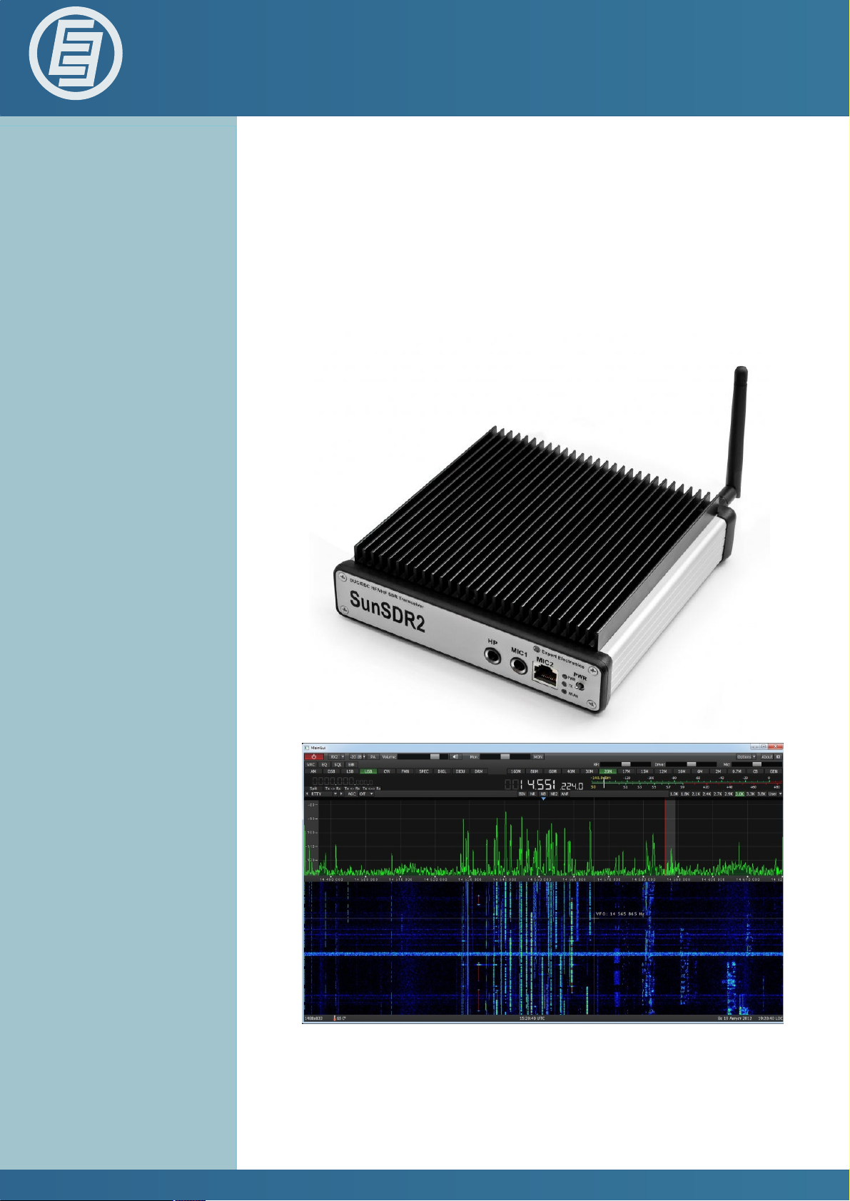
SunSDR2
- LAN interface
- Embedded WLAN router
- Remote control
- Small size
Expert Electronics LLC.
Quick Start
Version 1
www.sunsdr.com
Page 2

Expert Electronics DUC/DDC SDR Transceivers Series
Contents
Introduction ............................................................................................................... 2
1. Connection ............................................................................................................ 3
2. Transceiver Ethernet-connection setting .............................................................. 4
3. IP address setting in Windows Vista/7 ................................................................. 6
4. IP address setting in Windows XP ........................................................................ 8
5. Transceiver IP address change .......................................................................... 10
6. WLAN unit IP address change ............................................................................ 11
7. SunSDR2 WLAN – unit setting in AP Client mode ............................................. 12
8. Software interface description ............................................................................ 13
Conclusion .............................................................................................................. 17
1
Page 3

Expert Electronics DUC/DDC SDR Transceivers Series
Introduction
software. The same process is observed while
transmitting. Forming of necessary signal modulation
type is made by digital method right at the required
Please, spend 5 minutes on reading this document and
you will be able to start quickly to work with SunSDR2
transceiver and broadcast in a new way today. This
document gives answers to the majority of first
questions, appearing at a new user who starts working
with a transceiver of a new type.
You have bought the most up-to-date radio amateur
equipment which can be imagined for today. This
transceiver is a compound software defined radio,
allowing to provide high quality of signal processing both
in receiving and transmitting mode by modern digital
methods. PC use in transceiver allows to provide
qualitative service not only in receiving/transmitting, but
also to use the HAM LOGs and DIGI software without
wires.
Effective and quick mastering of SundSDR2 computer
transceiver is possible on condition that user has basic
frequency. From all the classical nodes there is only
preselector, power amplifier and low frequency filter for
PA in the scheme.
skills in using PC. It’s considered that computer terms
used in this manual on quick start are familiar to the user
and won’t cause any difficulties in searching one or
another tab in Windows 7 or Windows XP. For
visualization and simplicity, screenshots of dialogue
windows will be given here, necessary functions and
fields for editing will be outlined with coloured contour.
SunSDR2 transceiver is a software defined radio. It
means that you will need PC or laptop for work with
transceiver. PC controls transceiver, RX/TX modes,
band switching and data rate processing, coming from
and to transceiver. These rates by PC at the input and
output gives audio signal and receive microphone signal
and by transceiver they give HF-signal, transmitting into
the air.
The main feature of this transceiver and its basic
distinction from all the other recent output transceivers is
the use of absolutely new principle of radio signal
processing.
There is no frequency converting units in its classical
variant. The signal is converted almost from the
antenna, all the further signal processing is in the
2
Page 4

Expert Electronics DUC/DDC SDR Transceivers Series
1. Connection
Information about OpenGL support by video card can be
got at the sellers when buying the PC.
For starting SunSDR2 transceiver work the following
components are required:
· Transceiver power supply unit;
· PC;
· CW key (if it’s required);
· Microphone or telephone headset;
· Computer net LAN – cable;
· Antenna, tuned into radio amateur frequencies.
Let’s have a look at each component.
Power Supply unit must have power not less than 75
W, provide constant voltage of 15 V at the output with 5
Amperes load current. Under 15 V supply voltage
transceiver gives full output power of 20 W.
PC or laptop can be of any modern configuration,
produced during last 2-3 years. Recommended
configuration:
· 2 or 4 cores CPU Intel Core i3 or Core i5
· 2, 4 or 8 Gb RAM
· 40 Gb of available space in hard disk for transceiver
Microphone or Telephone headset can be either of the
simplest and cheapest as, for example, by Genius, or
developed specially for radio amateurs by Heil Sounds.
On the transceiver front panel there is a usual 6,3 mm
slot for electret microphone connecting. And also there
is a jack, compatible with Yaesu PTT-switches of MH-31
type. This jack allows to connect PTT-switches of such
popular transceiver as Yaesu FT-817/857/897 to
transceiver.
Receiving/transmitting modes control is produced by
pushing the PTT-footswitch (e.g. ЕЕ-РС-01), connected
to “PTT” jack on the back panel of the transceiver.
Computer net LAN – cable performs transceiver
connection to PC by ETHERNET-connection. PC
connection is also possible “by air”, via wireless net. The
easiest and quickest transceiver connection to PC is by
LAN-cable, supplied with the transceiver.
Antenna, tuned into radio amateur frequencies must
have impedance close to 50 Ohm at those bands where
work is planned.
and accompanying software.
· 17 – 24” of monitor screen.
· Video card with OpenGL 1.5 or more updated
support.
Transceiver software will work with less powerful PC
with Core2Duo and Dual Core, but it will cause
increased load level and it’s not always good. The more
powerful the PC the less resource the software will
occupy and the easier and more colourful “waterfall” and
panadapter will be painted.
OS must Windows XP 32/64bit or Windows 7 32/64bit.
3
Page 5
Expert Electronics DUC/DDC SDR Transceivers Series
mode and connection to WLAN access point, making
wireless connection out of one or several computers.
2. Transceiver Ethernet-connection setting
There are several ways of transceiver connecting to PC.
Let’s have a look at each in detail.
Connection by wire net connection is possible in 2
variants – direct connection to PC by wire Ethernet(LAN)
interface and by already working local net via router.
Direct connection to PC by wire Ethernet(LAN) interface.
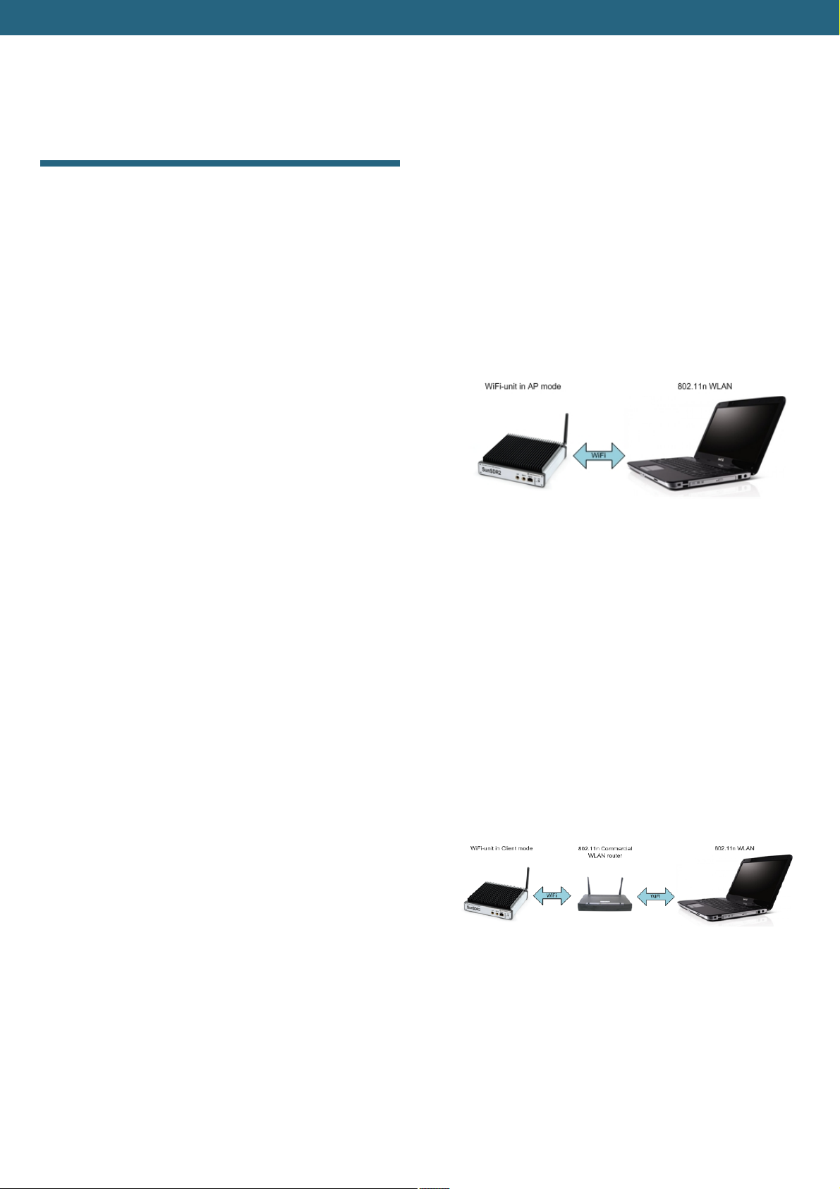
Direct connection to PC via built-into transceiver WLAN-
unit(without access point) as it is showed in Figure 2.1.
Standard 802.11n support with 150 Mbps data rate by
wireless PC card is compulsory for connection. Data
stream sampling rate recommended frequency from the
transceiver is 39062,5 Hz in this case. This rate is set up
in ExpertSDR2 software settings at Options->SDR tab.
1) Connect your transceiver to PC by LAN-cable,
supplied with transceiver.
2) Switch on the transceiver.
3) Set IP address in Windows XP or Windows Vista/7 as
it will be showed in section 3 and section 4.
4) Launch ExpertSDR2 software and push «Start».
If you have already local net with IP address not
192.168.16.ххх and you need to change IP address in
SunSDR2.
1) Connect your transceiver to PC by LAN-cable,
supplied with transceiver.
2) Switch on the transceiver.
3) Set static IP address in Windows XP or Windows
Vista/7 as it will be showed in section 3 and section 4
4) Launch ExpertSDR2 software and push «Start».
Figure 2.1 – Direct wireless connection to PC
1) Switch on the transceiver.
2) Push «L/W» (LAN/WLAN) at the back panel of the
transceiver
3) Wait till yellow led WLAN is lit on the front panel of
the transceiver.
4) Connect to SunSDR2 wireless net. Make sure that
connection rate on wireless net is 150 Mbps or more.
5) Launch ExpertSDR2 software and push «Start».
Connection to PC or to the net by access point as it is
showed in figure 2.2.
5) Change IP address in SunSDR2 as it is showed in
section 5.
6) Connect transceiver by LAN-cable to local net..
Now at any PC in local net ExpertSDR2 software can be
launched.
Transceiver connection by wireless interface.
In wireless variant of connection there are also two ways
of connection – direct connection to PC in a “point-point”
Figure 2.2 – Connection to PC by access point (router)
This scheme is used if you need to work with several
devices by wireless connection or you have already
wireless net, set according to your requirements. In this
4
Page 6

Expert Electronics DUC/DDC SDR Transceivers Series
case you will need to change SunSDR2 transceiver IP
address.
In this scheme computer is a WLAN access point (or Wi-
Fi router) in Access Point (AP) mode, SunSDR2 WLAN-
unit in AP Client mode.
If you have already WLAN net with IP address not
192.168.1.ххх and you need to change IP address in
SunSDR2.
1) Switch on the transceiver.
2) Connect SunSDR2 by LAN-cable.
3) Change IP address in the device as it is showed in
section 5.
4) Push «L/W» (LAN/WLAN) at the back panel of the
transceiver.
5) Wait till yellow led WLAN is lit on the front panel of
the transceiver.
6) Put SunSDR2 Wi-Fi unit into AP Client mode.
7) Launch ExpertSDR2 software and push «Start».
5
Page 7
Expert Electronics DUC/DDC SDR Transceivers Series
3) Choose network connection with SunSDR2
connected to it as it is showed in Figure 3.3., then
3. IP address setting in Windows Vista/7
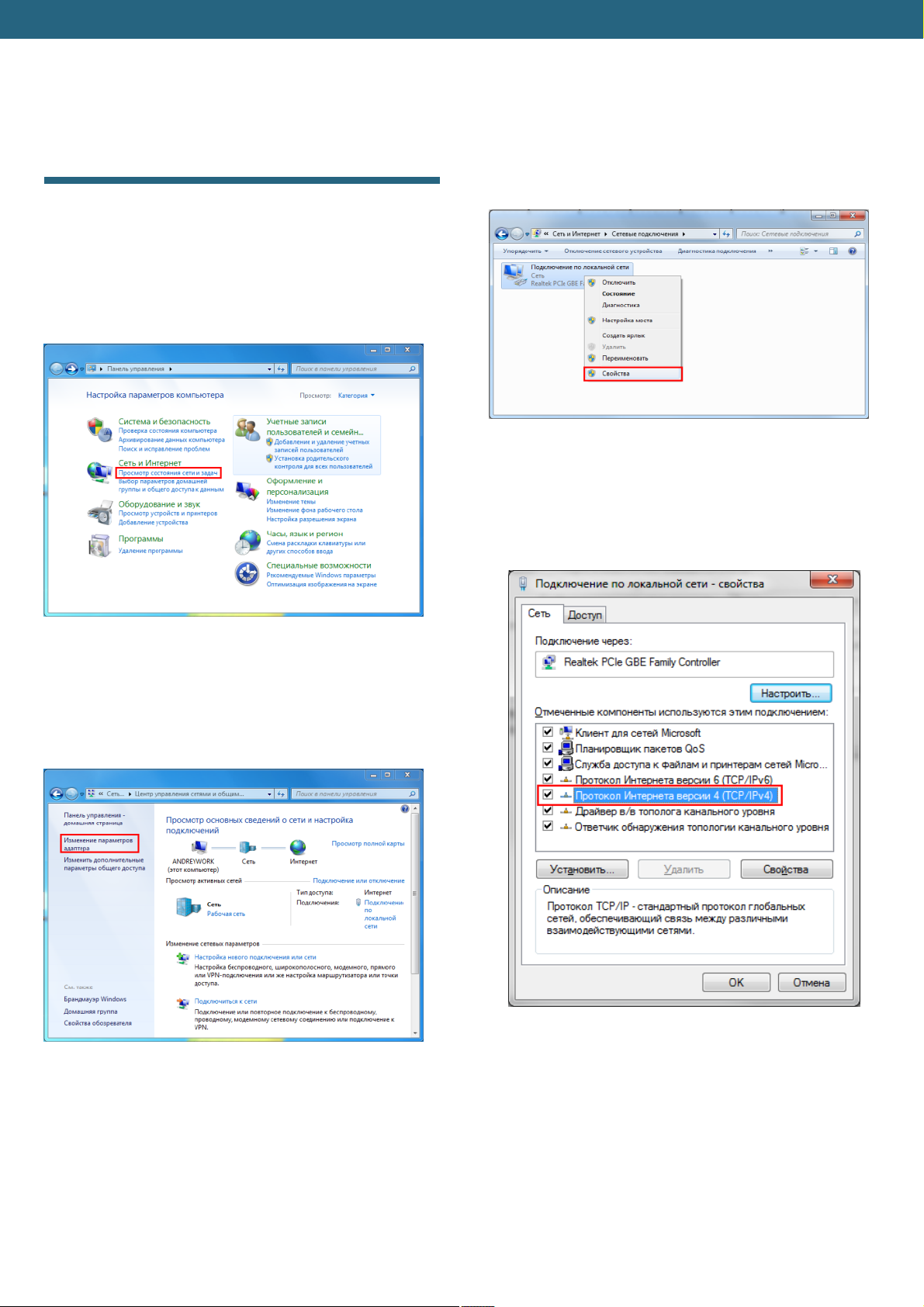
1) Push Start in the left lower corner in Windows and
choose Control panel. There will be a menu, shown
in figure3.1. In section Network and Internet choose
Tasks and networks status scan.
push the right button of the mouse on the icon and
choose Properties in the drop down window.
Figure 3.3 – Properties of connection by local net
4) In the new window put cursor on Internet protocol
version 4 and push Properties (view Figure 3.4.).
Figure 3.1 – PC parameters settings window
2) In the appeared window (view figure 3.2) choose
Adapter parameters change.
Figure 3.4 – Network settings properties window
Figure 3.2 – Viewing network data and connections
settings window
6
Page 8
Expert Electronics DUC/DDC SDR Transceivers Series
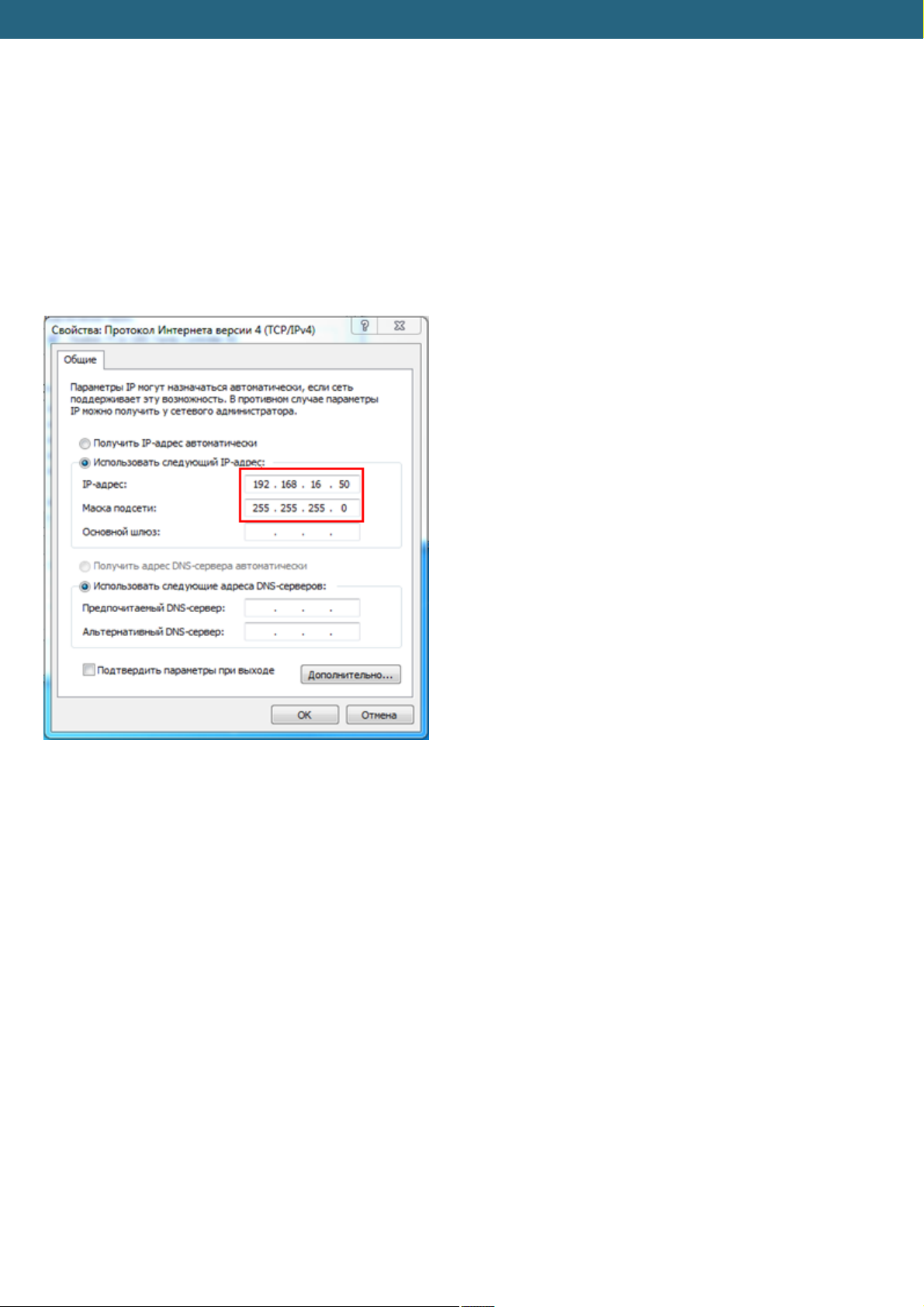
5) Set IP-address 192.168.16.50 and subnet mask
255.255.255.0 as it is showed in Figure 3.5. These
parameters are spread to the network card of PC.
Instead number 50 of IP-address you can set any
number, except 255 and 200. Transceiver IP-address
is 192.168.16.200 by default. After setting push OK.
Here IP-address setting is over.
Figure 3.5 – IP-address setting window
7
Page 9
Expert Electronics DUC/DDC SDR Transceivers Series
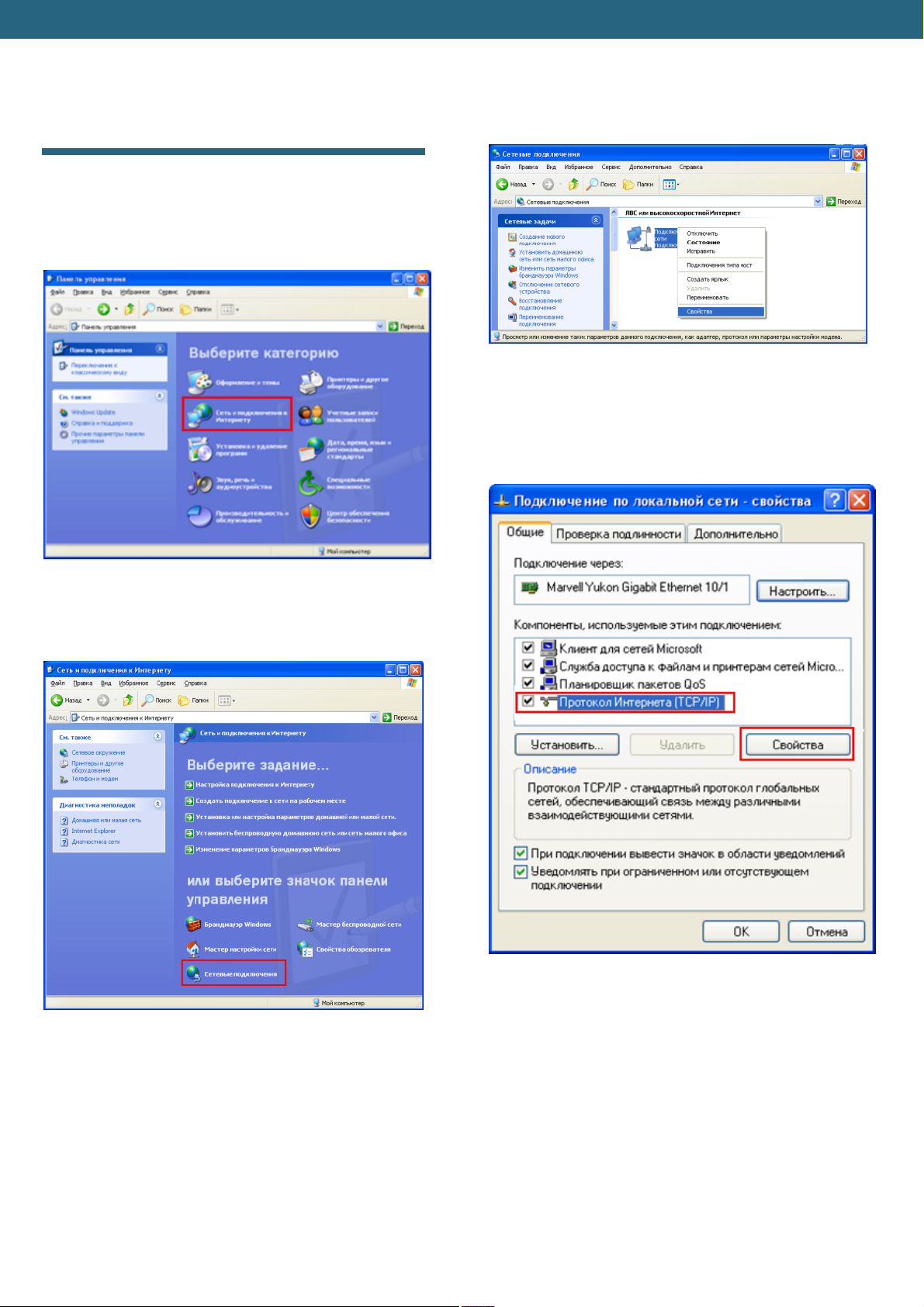
the icon and choose Properties in the drop down
menu (view Figure 4.3).
4. IP address setting in Windows XP
1) Push Start in the left lower corner in Windows and
choose Control panel. Then Network and Internet
connection. (view Figure 4.1.).
Figure 4.3 – Network connections
4) In the new window put cursor on Internet protocol
version 4 and push Properties (view Figure 4.4.).
Figure 4.1 - Windows XP control panel
2) Choose Network connection (view Figure 4.2)
Figure 4.4 – Connection by local net properties window
Figure 4.2 – Network connection choice
3) Choose network connection with SunSDR2
connected to it, push the right button of the mouse on
8
Page 10
Expert Electronics DUC/DDC SDR Transceivers Series
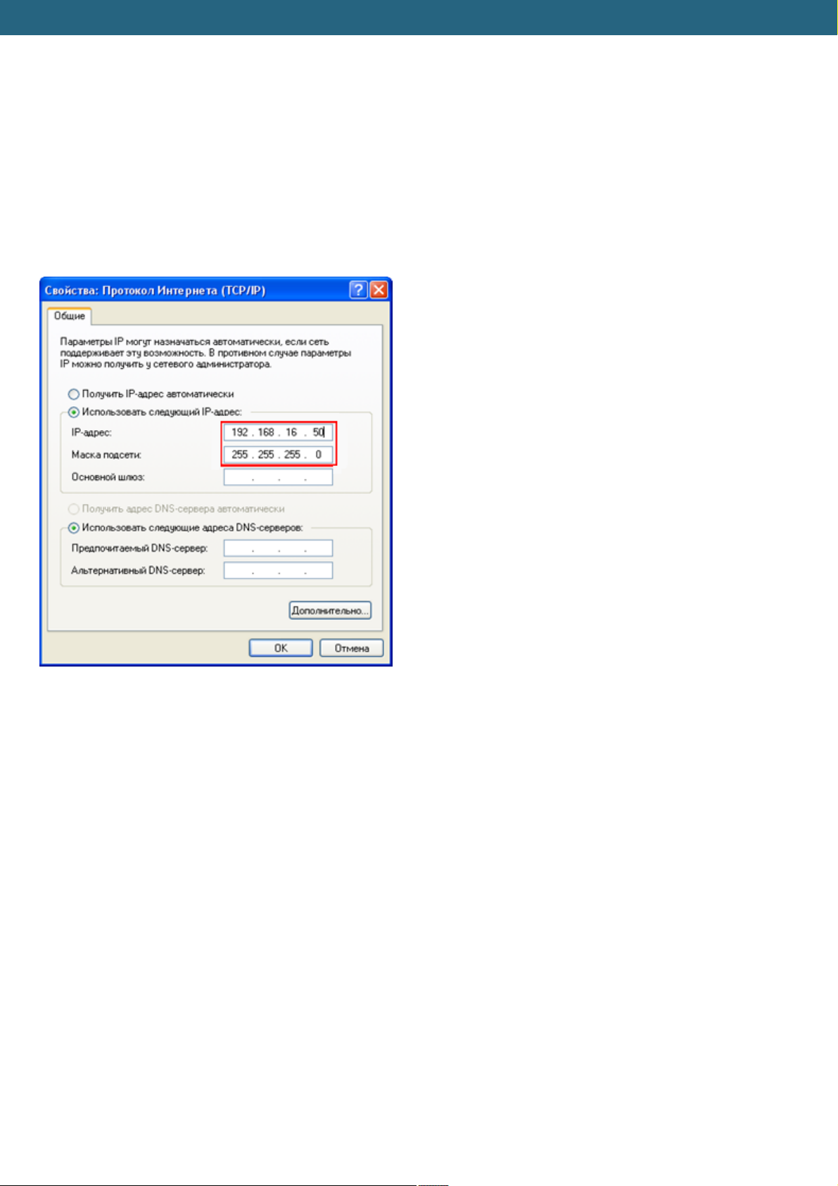
5) Set IP-address 192.168.16.50 and subnet mask
255.255.255.0 as it is showed in Figure 3.5. These
parameters are spread to the network card of PC.
Instead number 50 of IP-address you can set any
number, except 255 and 200. Transceiver IP-
address is 192.168.16.200 by default. After setting
push OK. Here IP-address setting is over.
Figure 4.5 – IP-address setting window
9
Page 11
Expert Electronics DUC/DDC SDR Transceivers Series
5. Transceiver IP address change
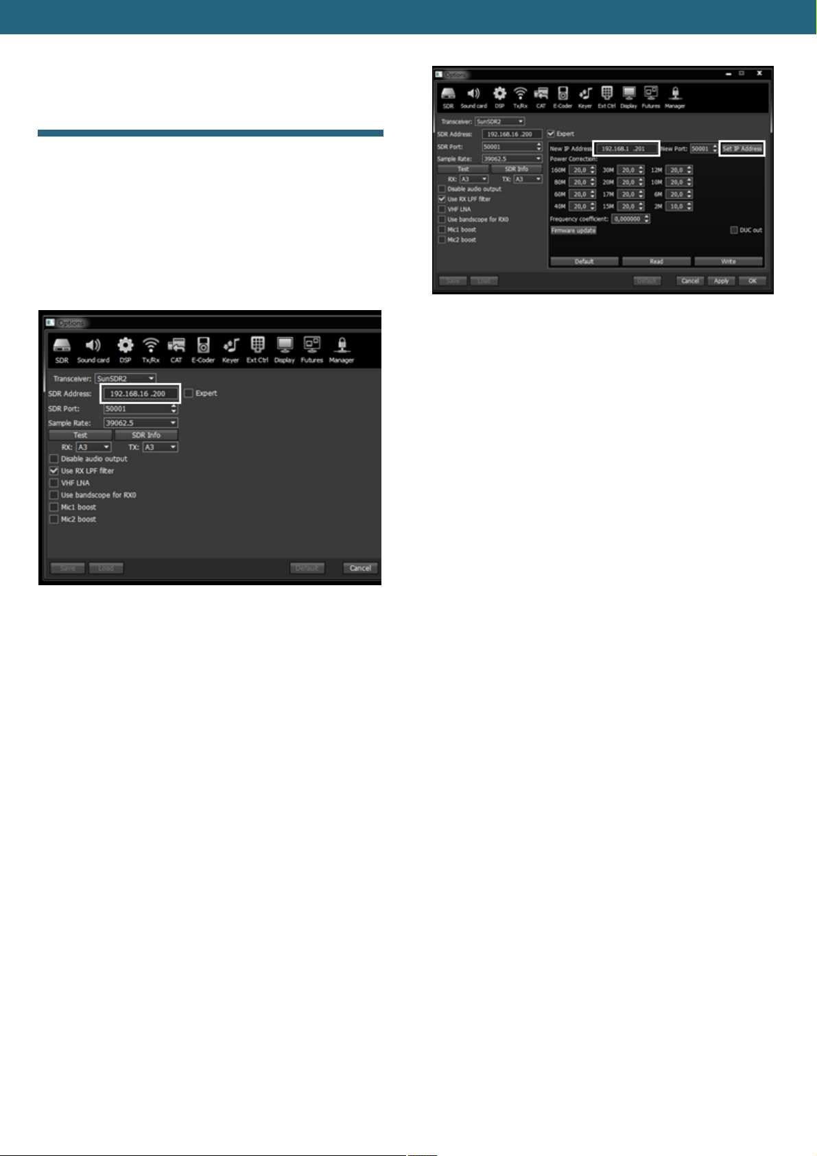
1) Launch ExpertSDR2 software and open settings
menu Options -> SDR. Put the current transceiver
IP-address in the field SDR Address, it’s
192.168.16.200 by default. Settings window is
showed in Figure 5.1.
Figure 5.2 – New IP-address setting in SunSDR2
transceiver
Figure 5.1 – Transceiver current IP-address setting in
ExpertSDR2 software
2) Tick off Expert. Then in the field New IP
Address put new IP-address, in our case it’s
192.168.1.200, and push Set IP Address. After this
action transceiv er will be available by new address
192.168.1.200 (view Figure 5.2).
10
Page 12
Expert Electronics DUC/DDC SDR Transceivers Series
6. WLAN unit IP address change
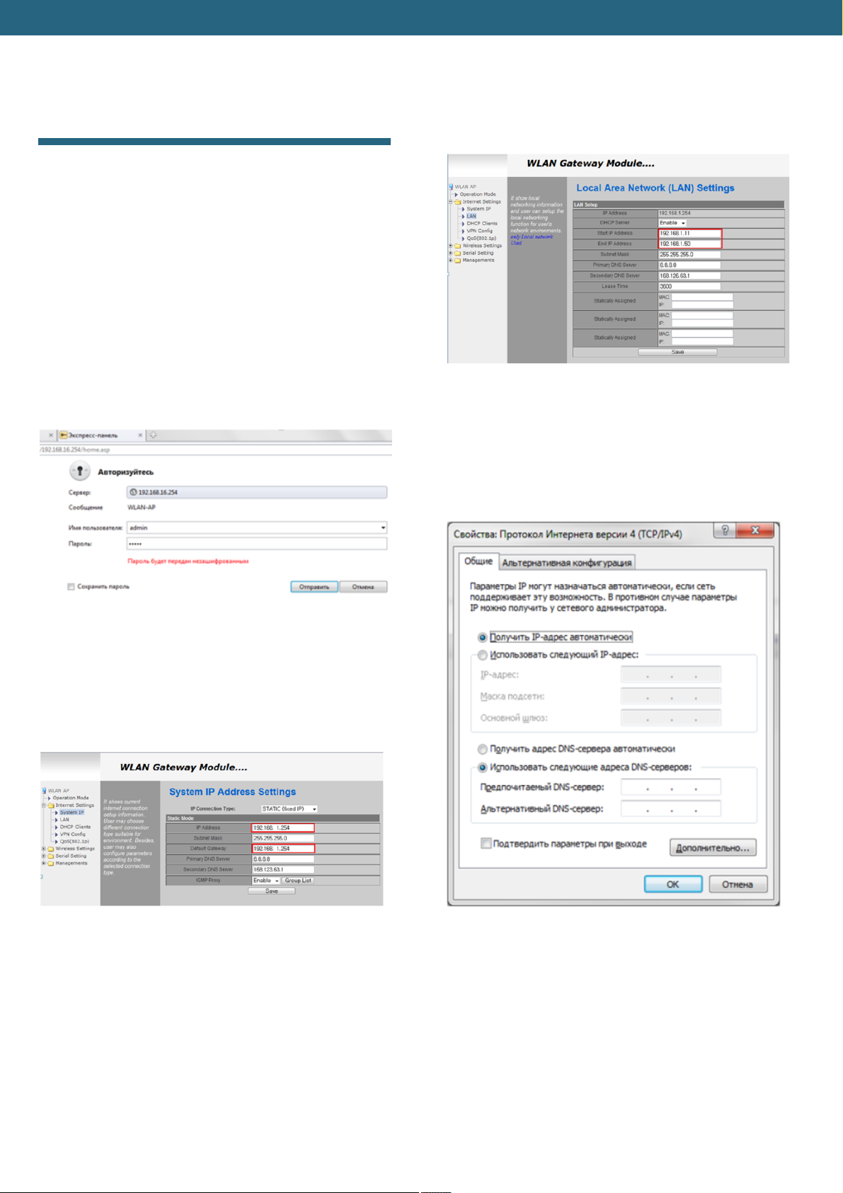
WLAN unit IP – address by default is 192.168.16.254. In
this part two examples how to change IP-address for
192.168.1.254 will be showed.
1) Connect to SunSDR2 wireless net and enter in
internet browser, for example Opera or Internet
Explorer, address field the following line
http://192.168.16.254. Then Login and Password
input field will appear, as it is showed in Figure 6.1. In
the appeared window we put user name admin,
password admin, and push Send.
write network addresses range. For example we put
them as it is showed in Figure 6.3 (outlined in red)
and push Save.
Figure 6.3 - DHCP service IP-addresses range setting
4) Disconnect SunSDR2 net. Enter PC WLAN card
properties and tick off «Get IP-address
automatically» (View Figure 6.4). Then connect
again to SunSDR2 net.
Figure 6.1 – User name and password input window
2) Enter the menu Internet Settings -> System IP. For
our example we give IP-address 192.168.1.254 to
WLAN-unit. Default Gateway is 192.168.1.254 and
push Save (View figure 6.2).
Figure 6.2 - WLAN unit IP-address input window
3) Disconnect SunSDR2 net. Give static IP-address
192.168.1.1 to Wi-Fi card and connect again to
SunSDR2 net. Now WLAN-unit is available by
192.168.1.254 address. Enter line
http://192.168.1.254 into browser and enter the
menu Internet Settings -> LAN. Here we should
Figure 6.4 - IP-address automatic receiving setting
11
Page 13
Expert Electronics DUC/DDC SDR Transceivers Series
7. SunSDR2 WLAN – unit setting in AP Client mode
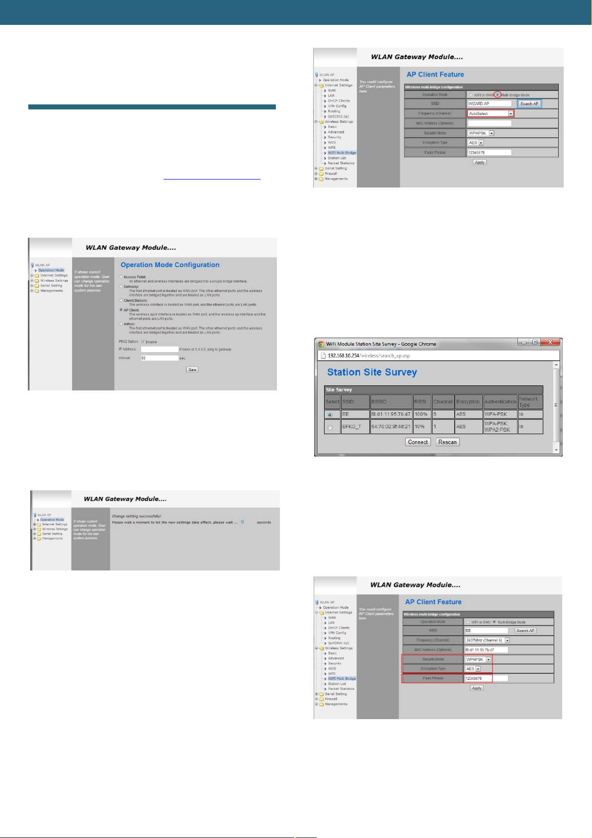
1) Set transceiver IP-address in access point local net
range.
2) Connect to transceiver SunSDR2 via WiFi.
3) Enter WLAN-unit settings http://192.168.16.254 via
internet browser. Login: admin, password: admin.
4) In Operation Mode menu tick off AP Client and
push Save (View figure 7.1)
Figure 7.1 - AP Client mode installation
5) If everything is done correctly there will be a window
as it is shown in figure 7.2. Wait till the countdown
finishes.
Figure 7.3 – AP-Client mode setting
7) In the appeared window choose access point
required and save Encryption and Authentication
parameter. For our example (View figure 7.4) EE
access point is chosen with the following parameters:
Encryption: AES
Authentication: WPA-PSK
Figure 7.4 – Access point choosing
Рисунок 7.2 – Information window about successful
setting change
6) In Wireless settings -> WiFi Multi Bridge menu tick
off Multi-Bridge Mode and in the channel stage drop
down списке list set AutoSelect (View figure 7.3).
Then push Search AP (access point search).
8) Then in AP Client Feature window set additional
Encryption and Authentication parameters for
chosen access point. In Pass Phrase field enter net
password. (View figure 7.5)
Figure 7.5 – Access point choosing
Note: Password 12345678, shown in figure above is
given as an example. It can differ.
12
Page 14
Expert Electronics DUC/DDC SDR Transceivers Series
8. Software interface description
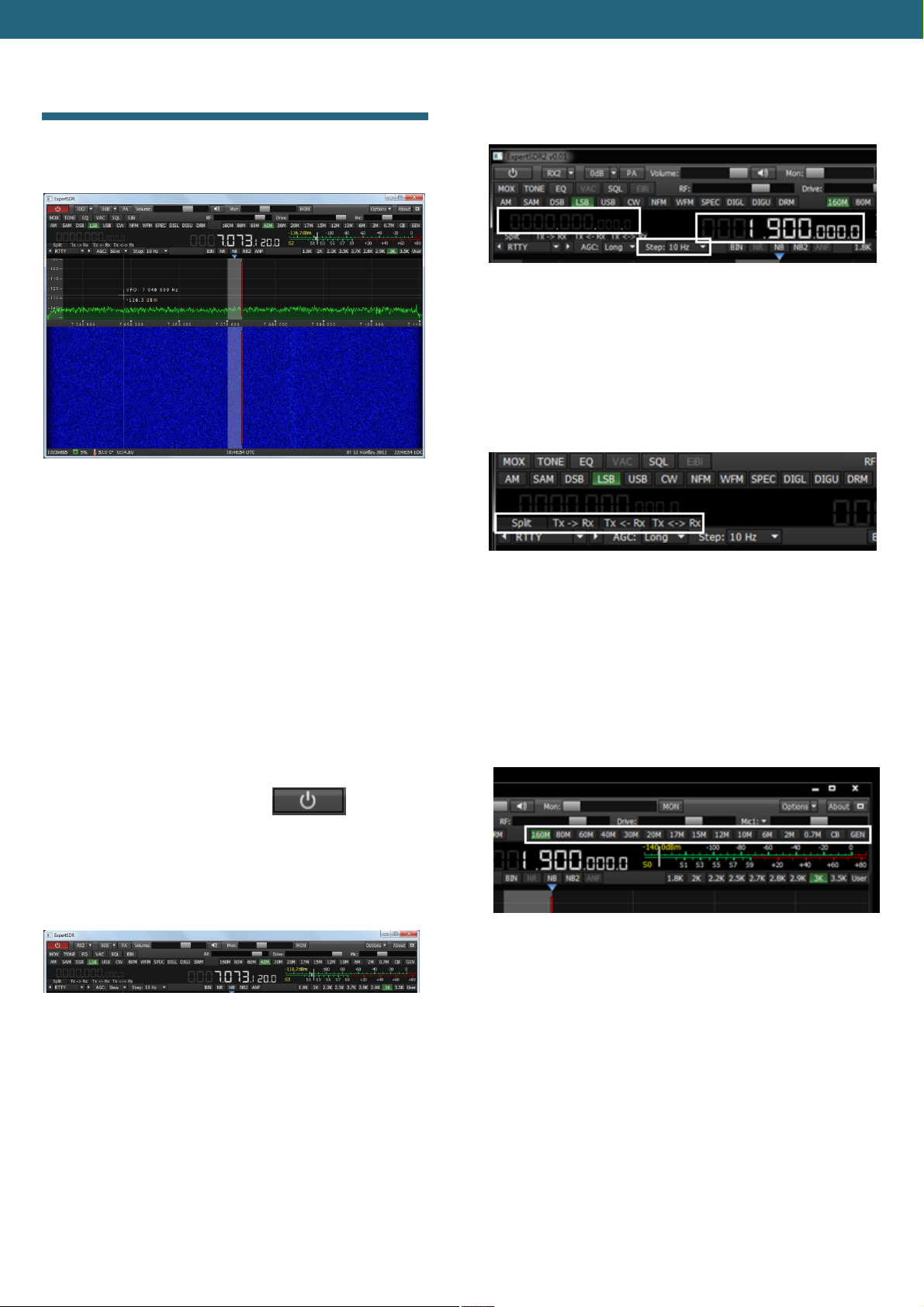
In figure 8.1 there is a working software panel.
prominent letters . Next to «STEP» button you can
choose frequency tuning step (view Figure 8.3).
Figureк 8.3 – Places on the panel, showing transceiver
frequency tuning
· RX-TX and «SPLIT» buttons are responsible for
switching VFO number and staggering (view Figure
8.4).
Figure 8.1 – Basic transceiver software panel
3\4 of software panel size is spectrum analyzer
panadapter field and “waterfall” field. Waterfall is a
convenient function, allowing to watch the signal change
dynamics with time.
1\4 of panel space occupy transceiver functions control
buttons, settings parameters and transceiver status
panels in the current situation.
Have a thorough look at buttons and power plants
appointment:
· Left upper button switches
transceiver on and off. «Options» button opens
general settings and preliminary parameters setting
windows. (view Figure 8.2).
Figure 8.4 – Places on the panel. responsible for
frequency exchange between VFO-A and VFO-B
· In the control panel showed below, in Figure 8.5,
there are band switching buttons. There is also quick
CB band opening button - “CB” button and possibility
to open general coverage - “GEN” button.
Figure 8.2 –General look of control panel with
transceiver parameters and status
· In the middle and from the left side of the basic panel
there are setting frequencies. In the middle of the
panel there is basic frequency VFO-A, frequency
VFO-B is from the left side written with less
Figure 8.5 – Band choice buttons
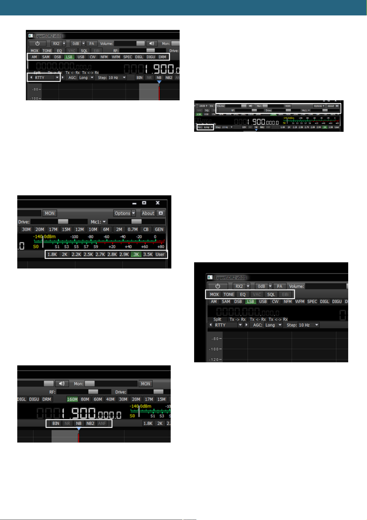
· In the place showed below, in Figure 7.6., there are
buttons for choosing a type of modulation used. In
the lower part of control panel one can set a type of
filter used for the required modulation mode.
13
Page 15
Expert Electronics DUC/DDC SDR Transceivers Series
· The following buttons are functions of transceiver
parameters operating control: volume control -
«Volume»; microphone level - «Mic»; output power
level - «Drive»; monitoring - «Mon»; HF manual
amplification – RF. AGC rate is regulated by a
separate field «AGC».(view Figure 8.9)
Figure 8.6 – Modulation type choosing buttons
· In the place showed below, in Figure 8.7, there are
Figure8.9 – Basic transceiver statuses power plants
receiving signal band pass filter choosing buttons.
For each modulation type one can choose required
band pass or tune their own band pass by pushing
«User»
Figure 8.7 – Band pass filter choosing buttons
· In the place showed below, in Figure 8.8, there are
special DSP buttons. They are noise reduction «NR»,
short time impulse noise blanker «NB» and «NB2»
and carrier signal automatic notch filter «ANF». As a
· In the place showed below, in Figure 8.10, there are
rare use functions buttons shortcuts. They are SQL
button, transmitting button - «MOX», virtual audio
cables setting and equalizer menu.
By «TONE» button transceiver is put into transmitting
mode and puts a carrier one.
«EiBi» button is now desactivated and reserved for
future functions.
separate DSP function pseudo stereo reception “BIN”
can be singled out.
Figure 8.8 – DSP – processing buttons
Figure 8.10 – Secondary regulations buttons
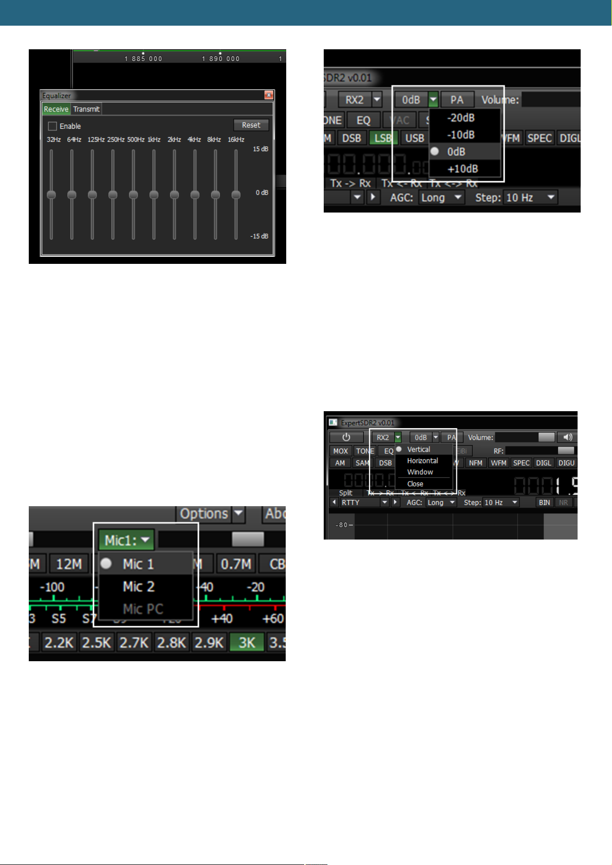
· In transceiver there is equalizer, activated by «EQ»
button. It has separate settings for receiving mode
(Receive) and separate settings for transmitting
mode (Transmit). (view Figure 8.11)
14
Page 16
Expert Electronics DUC/DDC SDR Transceivers Series
Figure 8.13 – Attenuator and preliminary amplifier
Figure 8.11 – Equalizer parameters settings window
Equalizer window can be moved easily along the screen
or can be fixed in a required panel place of transceiver
software.
· Transceiver has two microphone jacks, chosen by
pushing «MIC» button (view Figure 8.12). «Mic 1» is
chosen when electret microphone is connected to the
corresponded jack on the front panel of transceiver.
«Mic 2» is chosen when Yaesu transceiver PTT –
switch is connected. PC or laptop microphone
headset can be used, chosen as «Mic PC».
Transceiver gives a possibility to watch simultaneously
two radio bands and also receive signals simultaneously
from two receivers.
For the second receiver activation push «RX2» button,
next to software launching button (view Figure 8.14).
activation
Figure 8.12 – Microphone choosing buttons
· Attenuator on or preliminary amplifier is activated by
corresponded button within -20 dB up to +10 dB with
10 dB step (view Figure 8.13)
Figure 8.14 – Second receiver activation button
Operating controls arrangement and second receiver
panel duplicate completely first receiver window.
Receiver can be also put in different parts of the screen
or even in two different monitors.
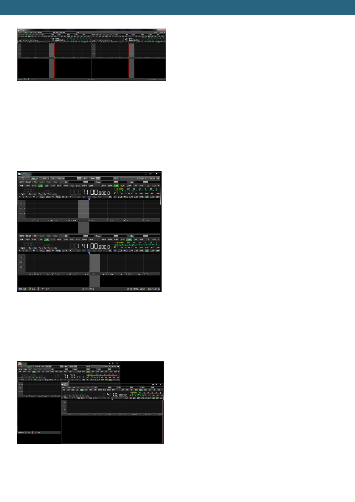
In figures below three possible configuration types of
receivers windows are given.
· In Figure 8.15 horizontal arrangement of two
receivers is showed. Such order is convenient if
operator’s work place equipped with one or better two
big monitors by diagonal from 22” and more.
15
Page 17
Expert Electronics DUC/DDC SDR Transceivers Series
Figure 8.15 – Horizontal arrangement of receivers’
windows
· In Figure 8.16 vertical arrangement of one receiver
above the other is showed. Such arrangement is
convenient when an old big monitor with 4:3 side
correlation is used or a modern monitor is put
vertically deliberately.
Figure 8.16 – Vertical arrangement of receivers’
windows
· In Figure 8.17 there is two receivers configuration
when each of them is in their own window and can be
moved easily along the screen.
Figure 8.17 – Two independent receivers’ windows
16
Page 18

Expert Electronics DUC/DDC SDR Transceivers Series
Conclusion
This brief description of transceiver connection to PC
and basic controls will allow you to master quickly this
up-to-date transceiver, learn its work and broadcast
quickly with it. More thorough description of all settings
and capabilities will be described in the full user manual.
Wish you success in mastering SDR\DDC-radio!
19.02.2013 Expert Electronics LLC.
17
 Loading...