


3002878-2011-01-14
GB
EBC20
Instructions for fitting, installation and operation
Job name: __________________________________
Fitter: ______________________________________
Installation date: ______________________________
EXHAUSTO CDT A/S www.exhausto-cdt.com
3002878-2011-01-14
1. |
Product information..................................................................................................................... |
|
|
|
4 |
|||
|
1.1 |
Delivery.............................................................................................................................................. |
|
|
|
5 |
||
|
1.2 |
Accessories....................................................................................................................................... |
|
|
|
5 |
||
|
1.3 |
Fitting................................................................................................................................................. |
|
|
|
5 |
||
|
|
1.3.1 Cable length...................................................................................................................... |
|
|
|
5 |
||
|
|
1.3.2 Connection diagram.......................................................................................................... |
|
|
|
6 |
||
|
1.4 |
Layout of the user interface............................................................................................................. |
|
|
|
7 |
||
|
|
1.4.1 Panel................................................................................................................................. |
|
|
|
7 |
||
|
|
1.4.2 Light emitting diodes and terminal board.......................................................................... |
|
|
|
8 |
||
|
|
1.4.3 Display............................................................................................................................... |
|
|
|
9 |
||
|
1.5 |
Introduction to the user interface.................................................................................................. |
|
|
|
10 |
||
|
1.6 |
Set-up............................................................................................................................................... |
|
|
|
11 |
||
|
|
1.6.1 Setting the chimney draft................................................................................................. |
|
|
|
11 |
||
|
1.7 |
Service menu................................................................................................................................... |
|
|
|
12 |
||
|
|
1.7.1 Overview of the service menu......................................................................................... |
|
|
|
13 |
||
|
|
1.7.2 Changing between the operating functions ( |
- |
- |
) |
..............................14 |
||
2. Pressure-controlled regulation of EXHAUSTO CDT chimney fan........................................ |
|
|
15 |
|||||
|
2.1 |
Use.................................................................................................................................................... |
|
|
|
15 |
||
|
2.2 |
Method of operation........................................................................................................................ |
|
|
|
15 |
||
|
2.3 |
Electrical connection...................................................................................................................... |
|
|
|
15 |
||
|
2.4 |
Sample wiring diagrams................................................................................................................. |
|
|
|
16 |
||
|
|
2.4.1 Singleor two boiler application...................................................................................... |
|
|
|
17 |
||
|
|
2.4.2 Single boiler application with potential free contact in boiler |
........................................... |
|
18 |
|||
|
|
2.4.3 Single boiler application with extra fail-safe protection using PDS.................................. |
|
19 |
||||
|
|
2.4.4 Single boiler application with a frequency converter....................................................... |
|
|
20 |
|||
|
|
2.4.5 2 boiler application with continuous operation of chimney fan........................................ |
|
21 |
||||
|
2.5 |
User menu........................................................................................................................................ |
|
|
|
22 |
||
|
|
2.5.1 Layout of the user menu.................................................................................................. |
|
|
|
22 |
||
|
|
2.5.2 Operating the user menu................................................................................................. |
|
|
|
22 |
||
|
2.6 |
Set-up............................................................................................................................................... |
|
|
|
22 |
||
|
2.7 |
Commissioning............................................................................................................................... |
|
|
|
23 |
||
3. 2-stage speed regulation of EXHAUSTO CDT chimney fan................................................... |
|
|
|
24 |
||||
|
3.1 |
Use.................................................................................................................................................... |
|
|
|
24 |
||
|
3.2 |
Method of operation........................................................................................................................ |
|
|
|
24 |
||
|
3.3 |
Electrical connection...................................................................................................................... |
|
|
|
24 |
||
|
3.4 |
Sample wiring diagrams................................................................................................................. |
|
|
|
24 |
||
|
|
3.4.1 1 x 2-stage boiler............................................................................................................. |
|
|
|
25 |
||
|
|
3.4.2 2 x 1-stage boilers........................................................................................................... |
|
|
|
26 |
||
|
3.5 |
User menu........................................................................................................................................ |
|
|
|
27 |
||
|
|
3.5.1 Layout of the user menu.................................................................................................. |
|
|
|
27 |
||
|
|
3.5.2 Operating the user menu................................................................................................. |
|
|
|
27 |
||
|
3.6 |
Set-up.............................................................................................................................................. |
|
|
|
28 |
||
|
|
3.6.1 Setting the chimney fan output........................................................................................ |
|
|
|
28 |
||
|
3.7 |
Commissioning............................................................................................................................... |
|
|
|
29 |
||
4. Pressure-controlled regulation of EXHAUSTO CDT supply air fan |
...................................... |
|
30 |
|||||
|
4.1 |
Use.................................................................................................................................................... |
|
|
|
30 |
||
|
4.2 |
Method of operation........................................................................................................................ |
|
|
|
30 |
||
|
4.3 |
Electrical connection...................................................................................................................... |
|
|
|
30 |
||
|
4.4 |
Sample wiring diagram................................................................................................................... |
|
|
|
30 |
||
|
|
4.4.1 Connection of frequency converter/MPR relay................................................................ |
|
|
|
31 |
||
|
4.5 |
User menu........................................................................................................................................ |
|
|
|
32 |
||
|
|
4.5.1 Operating the user menu................................................................................................. |
|
|
|
32 |
||
|
4.6 |
Set-up............................................................................................................................................... |
|
|
|
33 |
||
|
4.7 |
Commissioning............................................................................................................................... |
|
|
|
33 |
||
5. List of alarms and troubleshooting.......................................................................................... |
|
|
|
34 |
||||
|
5.1 |
Alarm handling................................................................................................................................ |
|
|
|
34 |
||
|
|
5.1.1 Resetting a current alarm................................................................................................ |
|
|
|
34 |
||
|
|
5.1.2 Resetting the alarm log................................................................................................... |
|
|
|
34 |
||
|
|
5.1.3 Alarm overview................................................................................................................ |
|
|
|
35 |
||
|
5.2 |
More troubleshooting..................................................................................................................... |
|
|
|
36 |
||
|
|
5.2.1 Program running.............................................................................................................. |
|
|
|
36 |
||
|
|
5.2.2 Communication error....................................................................................................... |
|
|
|
36 |
||
6. |
Technical specifications............................................................................................................ |
|
|
|
37 |
|||
7. |
EU declaration of conformity.................................................................................................... |
|
|
|
38 |
|||
|
|
|
|
|
|
|
||
|
|
|
|
2 / 40 |
|
|
|
|
|
|
|
|
|
|
|
|
|
|
|
|
|
|
|
|
|
|
3002878-2011-01-14
Symbol Legend:
The following terms are used throughout this manual to bring attention to the presence of potential hazards or to important information concerning the product.
Prohibition symbol:
Failure to observe instructions marked with a prohibition symbol may result in serious injury or death.
Danger symbol:
!personal injury and/or damage to the unit.
!TO REDUCE THE RISK OF FIRE, ELECTRICAL SHOCK OR INJURY TO PERSONS, OBSERVE THE FOLLOWING:
•Use this unit in the manner intended by the manufacturer. If you have questions, contact the supplier at the address or telephone number listed on the back of the manual.
•Before servicing or cleaning the unit, switch off at service panel and lock service panel to prevent power from being switched on accidentally.
•Installation work and electrical wiring must be done by a qualified person(s) in accordance with applicable codes and standards.
•Follow the appliance manufacturer’s guidelines and safety standards and the local code authorities
•This unit must be grounded.Failure to observe instructions marked with a danger symbol may result in
No special requirements. Disposal should be carried out in accordance with statutory regulations related to the disposal of electronic waste.
3 / 40
Product information
3002878-2011-01-14
1. Product information
Description
The EBC20 (EXHAUSTO CDT Boiler Control) is a specially designed control component for constant pressure regulation of chimney draft.
By changing the operating mode, the EBC20 can also:
•Act as a 2-stage speed regulator (see section 3).
•Control the supply of fresh air to the boiler room (see section 4).
Layout of the instructions
The EBC20 can control an EXHAUSTO CDT chimney fan or an EXHAUSTO CDT supply air fan.
There are seven sections to the instructions:
•Read section 1. ”Product information”.
•Read the section that deals with the required control methods:
››Section 2: Pressure-controlled regulation of EXHAUSTO CDT fans (factory-set). ››Section 3: Two-step speed regulation of EXHAUSTO CDT fans.
››Section 4: Pressure-controlled regulation of EXHAUSTO CDT supply air fan.
• Read sections 5–7.
Section 2,3, and 4 deals with the following:
Section 2: Pressure-controlled regulation of EXHAUSTO CDT chimney fans (default).
•The EBC20 ensures and monitors constant pressure in a chimney.
•The EBC20 is designed for use with boiler systems with 1- and 2-stage burners.
•The EBC20 can also be used for boiler systems with modulating burners.
•The control system monitors chimney draft and shuts down the burner in the event of errors (the alarmdiode on the EBC20 will turn on).
•The control system is intended for both solid fuel boilers, atmospheric gas boilers, condens and forced draft boilers for oil and gas.
•The EBC20 can control a chimney fan directly or indirectly via a frequency converter.
Section 3: 
 2-stage speed regulation of EXHAUSTO CDT chimney fans.
•The EBC20 can be used as a 2-stage speed regulator for EXHAUSTO CDT chimney fans.
•The EBC20 monitors chimney draft and shuts down the burner in the event of errors (the alarmdiode on the EBC20 will turn on).
•The control system is intended for 1- or 2-stage atmospheric gas boilers.
•The EBC20 can control a chimney fan directly or indirectly via a frequency converter.
Section 4: Pressure-controlled regulation of EXHAUSTO CDT supply air fans.
•The EBC20 can be used to control an EXHAUSTO CDT BESB or BESF box fan.
•The EBC20 ensures and monitors constant pressure in a boiler room.
•The control system monitors the pressure in the boiler room and shuts down the burner in the event of errors (the alarmdiode on the EBC20 will turn on).
•The EBC20 can control a supply air fan directly or indirectly via a frequency converter.
4 / 40
Product information
3002878-2011-01-14
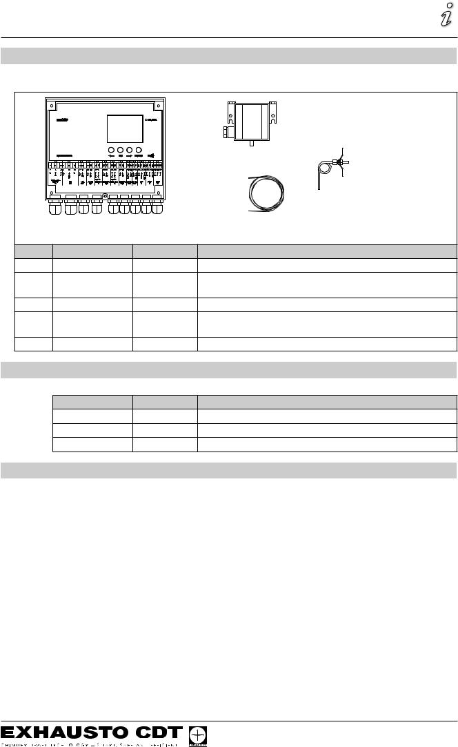
1.1 Delivery
The EBC20 is delivered with the following:
|
|
|
B |
|
|
|
C |
|
|
|
D |
A |
|
|
|
Pos. |
Part |
Item no. |
Function |
A |
EBC20 |
EBC20EU02 |
Controls EXHAUSTO CDT fans and chimney fans. |
B |
Pressure trans- |
0501022 |
Measures difference air pressure in the boiler room or chim- |
|
ducer (XTP) |
|
ney, or outdoor atmospheric pressure. |
C |
Measuring probe |
0500512 |
Measures pressure in the chimney. |
D |
2 m silicone hose |
2000335 |
Supplies the pressure transducer (XTP) with reference pres- |
|
|
|
sure from the measuring probe or from outdoors. |
|
Instructions |
3002878 |
Instructions for fitting, installation and operation. |
1.2 Accessories |
|
|
|
|
Part |
Item no. |
Function |
|
Relay |
ES12 |
If more than 2 boilers are connected. |
|
Extern PDS |
PDSBOX |
Measures pressure in chimney. |
|
Isolation switch |
REP-AFB |
Isolation switch |
1.3 Fitting
1.3.1 Cable length
Max. cable length between EBC20 and XTP: 100 m.
Max. cable length between EBC20 and chimney fan / fan: 100 m.
5 / 40
Product information
3002878-2011-01-14
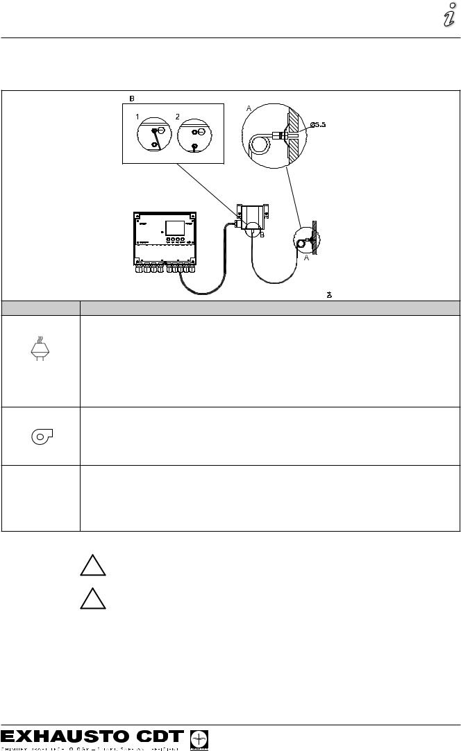
1.3.2 Connection diagram
The EBC20 is to be fitted and connected as shown in the diagram below.
Control of … |
Fitting procedure |
Chimney fan • Fit the EBC20 and the pressure transducer (XTP) in the boiler room.
•Fit the measuring probe(A) in the boiler flue or in the manifold. However, for atmospheric boilers, the probe must always be positioned after the draft hood.
•Connect the hose from the measuring probe to the negative terminal on the pressure transducer (B”1”).
Remark! • When the measuring probe is placed outside , it must be mounted in a way that prevents condensate or ice from being formed. If necessary the probe can be straigtened and placed so the condensate may run out.
Supply air fan • Fit the EBC20 and pressure transducer (XTP) in the boiler room.
•Connect the hose for measuring reference pressure (outdoor atmospheric pressure) to the negative terminal (B”1”) on the pressure transducer. Run the hose outside the building to a place that is not affected by wind, rain, etc. If appropriate, fit the free end of the hose in a box as described at the top of the next page.
Note |
Special aspects if you require positive pressure* in the chimney/boiler room: |
•Connect the hose to the positive terminal on the pressure transducer (B”2”)
•In menu 16 (see page 13) set the value to 2 (positive pressure). For operation of the service menu, see page 12
•Please note that the EBC20 is supplied with only 2 m of hose.
NB!
*The default setting of the EBC20 is for negative pressure regulation, but local
!authority requirements may state that positive pressure must be maintained.
!The pressure transducer cannot be mounted inside an air tight enclosure. It uses the atmospheric pressure as reference pressure.
6 / 40
Product information
3002878-2011-01-14
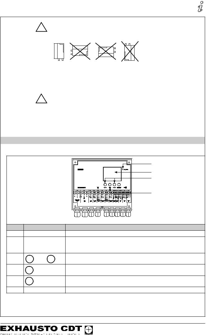
!Make sure to position the pressure transducer the right way up.
NB
Do not blow into the valves on the XTP.
Outdoor fitting of the pressure transducer (XTP)
When fitting the pressure transducer outdoors, make sure to position it in a place
!where it is not affected by wind, rain, etc. When fitted outdoors, the pressure transducer should ideally be positioned in a box with a hole (dia. 2 mm) in the bottom. The purpose of this box is to assure correct reference pressure – through the hole – and to keep water out.
If the pressure transducer is positioned in a place where insects have access to the free end, fitting a sinter filter is recommended.
1.4 Layout of the user interface
1.4.1 Panel
A
B
C
F 
 D
D
E
Pos.
A
B
C
D
E
F
Part
Alarm
Display
and
RESET
OK
Light emitting diodes
Function
•indicates alarms
•displays operation and changes in the user interface (menu system)
•indicates alarms
•shows normal operation status
•forward or back in the menu system
•increase/reduce set point
•reset alarm
•return to operation screen
•select menu item
•confirm/save changes of set point or parameters
•shows status of inputs and outputs
7 / 40
Product information
3002878-2011-01-14
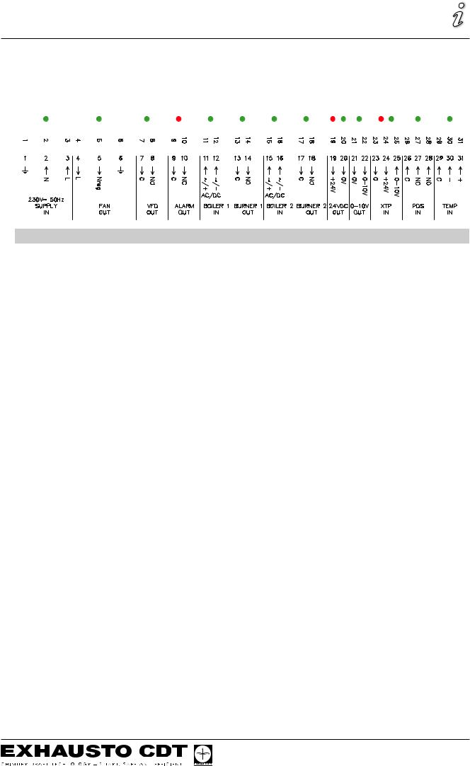
1.4.2 Light emitting diodes and terminal board
The chart below lists the connection options for the terminal boards and explains the various colours of the light emitting diodes.
|
|
|
|
|
|
|
|
|
|
|
|
|
|
|
|
|
|
|
|
|
|
|
|
|
|
|
|
|
|
|
|
|
|
|
|
|
|
|
|
|
|
|
|
|
|
|
|
|
|
|
|
|
|
|
|
|
|
|
|
|
|
|
|
|
|
|
|
|
|
|
|
|
|
|
|
|
|
|
|
|
|
|
|
|
|
|
|
|
|
|
|
|
|
|
|
|
|
|
|
|
|
|
|
|
|
|
|
|
|
|
|
|
|
|
|
|
|
|
|
|
|
|
|
|
|
|
|
|
|
|
|
|
|
|
|
|
|
|
|
|
|
|
|
|
|
|
|
|
|
|
|
|
|
|
|
|
|
|
|
|
|
|
|
|
|
|
|
|
|
|
|
|
|
|
|
|
|
|
|
|
|
|
|
|
|
|
|
|
|
|
|
|
|
|
|
|
|
|
|
|
|
|
|
|
|
|
|
|
|
|
|
|
|
|
|
|
|
|
|
|
|
|
|
|
|
|
|
|
|
|
|
|
|
|
|
|
|
|
|
|
|
|
|
|
|
|
|
|
|
|
|
|
|
|
|
|
|
|
|
|
|
|
|
|
|
|
|
|
|
|
|
|
|
|
|
|
|
|
|
|
|
|
|
|
|
|
|
|
|
|
|
|
|
|
|
|
|
|
|
|
|
|
|
|
|
|
|
|
|
|
|
|
|
|
|
|
|
|
|
|
|
No. |
Designation |
Max. load |
Meaning when the light diode is … |
||||||||||||||||||||||||||||||||||||||||||
1, 2 & 3 |
|
|
SUPPLY IN |
230-240VAC +/- 10% |
green: the EBC20 is connected to a power supply |
||||||||||||||||||||||||||||||||||||||||
4, 5 & 6 |
|
|
FAN OUT |
3A |
green: the triac output is active |
||||||||||||||||||||||||||||||||||||||||
7 & 8 |
|
|
|
VFD OUT |
250VAC, 8A, AC3 |
green: the relay is connected |
|||||||||||||||||||||||||||||||||||||||
9 & 10 |
|
|
ALARM OUT |
250VAC, 8A, AC3 |
red: the relay is open |
||||||||||||||||||||||||||||||||||||||||
11 & 12 |
|
|
BOILER 1 IN |
18 - 230VDC / VAC |
green: the input is active |
||||||||||||||||||||||||||||||||||||||||
13 & 14 |
|
|
BURNER 1 OUT |
250VAC, 4A, AC3 |
green: the relay is connected |
||||||||||||||||||||||||||||||||||||||||
15 & 16 |
|
|
BOILER 2 IN |
18 - 230VDC / VAC |
green: the input is active |
||||||||||||||||||||||||||||||||||||||||
17 & 18 |
|
|
BURNER 2 OUT |
250VAC, 4A, AC3 |
green: the relay is connected |
||||||||||||||||||||||||||||||||||||||||
19 & 20 |
|
|
24 VDC OUT |
100mA |
green: power supply OK |
||||||||||||||||||||||||||||||||||||||||
|
|
|
|
|
|
|
|
|
|
|
|
|
|
|
|
|
|
|
|
|
|
|
|
red: overload |
|||||||||||||||||||||
21 & 22 |
|
|
0 - 10 V OUT* |
20mA |
green: the output is active |
||||||||||||||||||||||||||||||||||||||||
23, 24 & 25 |
XTP IN |
|
|
|
|
|
|
|
|
|
|
green: XTP connected |
|||||||||||||||||||||||||||||||||
|
|
|
|
|
|
|
|
|
|
|
|
|
|
|
|
|
|
|
|
|
|
|
|
red: return voltage >12 VDC |
|||||||||||||||||||||
26, 27 & 28 |
PDS IN ** |
|
|
|
|
|
|
|
|
|
|
green: C & NO are connected |
|||||||||||||||||||||||||||||||||
29, 30 & 31 |
TEMP IN |
|
|
|
|
|
|
|
|
|
|
green: temperature sensor connected |
|||||||||||||||||||||||||||||||||
*Cable length between 0-10V output (terminal 21 & 22) must not exceed 100m and must be of a shielded cable 3x0,75 mm2.
**Terminals 26, 27 & 28 can however also be used for connecting other auxiliary surveillance equipment.
8 / 40

Product information
3002878-2011-01-14
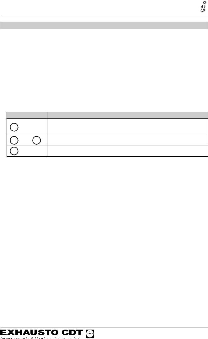
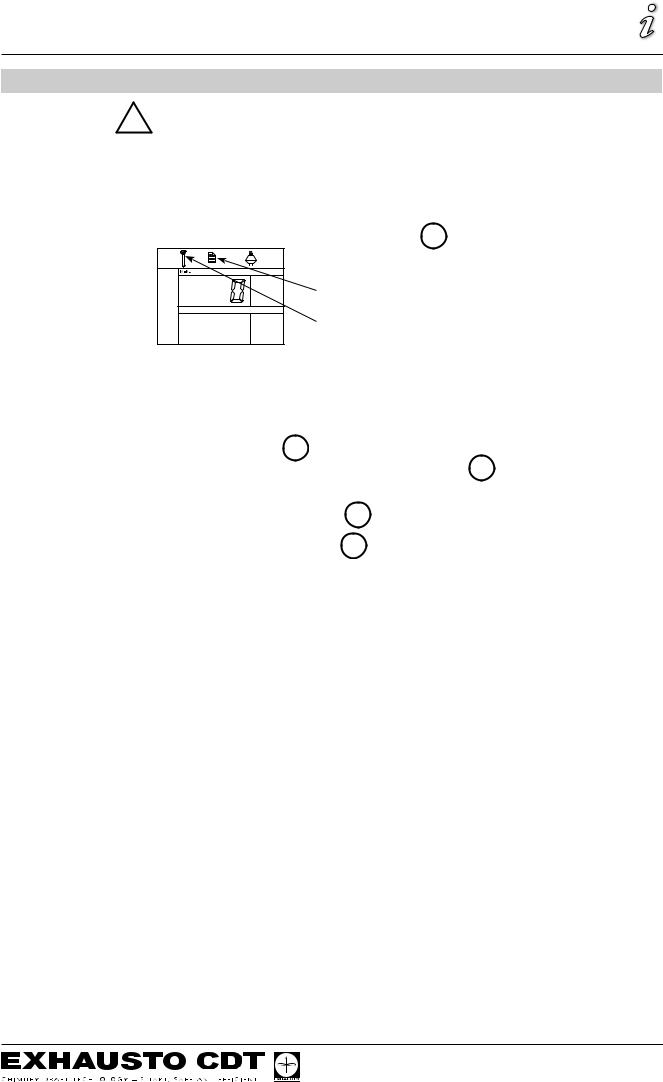
1.4.3 Display
The diagram below shows the layout of the display on the EBC20. All possible display values are stated:
1 |
2 |
3 |
4 |
5 |
6 |
7 |
8 |
9 |
14 |
10 |
|
|
||
15 |
11 |
|
|
||
16 |
12 |
|
17 |
||
13 |
Pos. |
Shows … |
1Symbol indicating the connection of Z-wave
2Symbol for service menu
3Symbol for alarms. Displayed in the event of an alarm, along with the illumination of the alarm diode.
4Symbol for the operational settings of the service menu (see section 1.6) and the alarm log.
5Symbol for overheating
6Symbol for 2-stage speed regulation of EXHAUSTO CDT chimney fan
7Symbol for pressure-controlled regulation of EXHAUSTO CDT chimney fan
8Symbol for pressure-controlled regulation of EXHAUSTO CDT supply air fan
9Symbol indicating:
•PDS error
•PDS check (flashing)
10• Operation screen: current pressure
•Menu screen: current menu
11Units
12Units
13Menu screen (“VALUE” and, in some cases, “SETPOINT” displayed): Setpoint for the menu item in question
14Temperature symbol, indicates:
•Operation screen: current temperature
•Menu screen: temperature parameter setting
15Timer indicator
16Pressure symbol indicating that:
•Operation screen: Pos. 10 is displaying pressure
•Menu screen: You are currently altering a pressure parameter
17Symbol for commissioning
9 / 40
Product information
3002878-2011-01-14
1.5 Introduction to the user interface
Display
The purpose of the display (see previous page) is to present:
•Operating information (pressure, etc.)
•Alarms
•Setpoints
•Parameters
Menu structure
The menu system in the EBC20 contains:
•User menu (for operation by daily users).
•Service menu (for operation by qualified technical staff).
Layout of the user interface
The user interface is operated through four buttons with the following functions:
Button
OK
and
RESET
Function
•Activate the user menu
•Edit and save settings
•Activate service menu (press and hold for 3 seconds)
•Go to menu item, and adjust value
•Return to operation screen from any point in the menu system
•Reset alarm when manual reset is selected in menu 25, see page 13
10 / 40
Product information
3002878-2011-01-14
1.6 Set-up
1.6.1 Setting the chimney draft
To set the pressure in the chimney, follow the procedure detailed below.
Step. Action... |
The display shows... |
1
•Start the heating system.
•The EBC20 displays the actual pressure (in this
example 30 Pa).
2
• Briefly press OK to enter the user menu.
3
• Press OK
• Press and
until the required pressure
appears in the lower display.
4
• Press OK to confirm the setting
5To finish and return to the operation screen, press RESET
NB
This procedure only applies to setting up the chimney draft.
If you wish to:
•Set the EBC20 up for 2-stage speed regulation of a chimney fan, see page 24.
•Set the EBC20 up for pressure control of a supply air fan, see page 30.
11 / 40
Product information
3002878-2011-01-14
1.7Service menu
!The service menu is only to be operated by qualified staff.
For an overview of the service menu, see page 13.
Operation of the user menus is described in sections 2, 3 and 4.
Navigation in the service menu
• To activate the service menu, press and hold OK for 3 seconds.
The service menu operation settings
Service menu
•Operation is carried out using the buttons as described in section 1.5 Introduction to the user interface, page 10.
•The upper display (pos. 10 on page 9) presents the number of the menu, with the set point for this menu being shown in the lower display (pos. 13 on page 9).
•Menus whose last digit is “0” are exit menus. These are used to navigate one level back. To do so, press OK .
•To activate the editing options for a menu item, press OK . The set point will start flashing.
•Confirm and save selection with OK .
•To exit the service menu, press RESET. This will take you back to the operation screen.
Alternatively, you can navigate back one level at a time if you wish to set multiple menu items.
For examples of how to use the service menu, see 1.7.2 on page 14.
12 / 40
 Loading...