

Page 1

PPM-350C
PON Power Meter
User Guide
Page 2

Copyright © 2009–2012 EXFO Inc. All rights reserved. No part of this publication may
be reproduced, stored in a retrieval system or transmitted in any form, be it
electronically, mechanically, or by any other means such as photocopying,
recording or otherwise, without the prior written permission of EXFO Inc. (EXFO).
Information provided by EXFO is believed to be accurate and reliable. However, no
responsibility is assumed by EXFO for its use nor for any infringements of patents or
other rights of third parties that may result from its use. No license is granted by
implication or otherwise under any patent rights of EXFO.
EXFO’s Commerce And Government Entities (CAGE) code under the North Atlantic
Treaty Organization (NATO) is 0L8C3.
The information contained in this publication is subject to change without notice.
Trademarks
EXFO’s trademarks have been identified as such. However, the presence or
absence of such identification does not affect the legal status of any trademark.
Units of Measurement
Units of measurement in this publication conform to SI standards and practices.
Patents
EXFO’s Universal Interface is protected by US patent 6,612,750.
The PPM-350C is protected by US patent no. 7,187,861, German Utility Patent no. 20
2004 021 208.0, and subject of several pending national entries in other countries
under the Patent Cooperation Treaty.
Version number: 4.0.0
ii
Page 3

Contents
Certification Information .................................................................................. v
European Community
Declaration of Conformity .......................................................................... vi
1 Introducing the PPM-350C PON Power Meter ......................... 1
Main Features ................................................................................................... 1
Available Models .............................................................................................. 3
Power Sources .................................................................................................. 3
Typical Applications .......................................................................................... 4
Conventions ...................................................................................................... 5
2 Safety Information ................................................................... 6
Laser Safety Information (Models with VFL) ...................................................... 6
Electrical Safety Information ............................................................................. 6
Ultra-High-Power™ Safety Information ............................................................. 7
3 Getting Started with Your PON Power Meter .......................... 8
Turning the Unit On and Off ............................................................................. 8
Activating Automatic Shutdown (Auto-Off) .................................................... 10
Installing the EXFO Universal Interface (EUI) ................................................... 10
Cleaning and Connecting Optical Fibers ......................................................... 11
Nulling Electrical Offsets ................................................................................. 12
4 Configuring Thresholds, Correction Factors, Wavelength List,
and Storage Details ................................................................ 13
5 Working in FTTx Mode ............................................................ 14
Selecting a Threshold Set ................................................................................ 14
Testing in Pass/Fail Mode or in Normal Mode .................................................. 16
6 Working in OPM Mode ............................................................ 18
7 Managing Test Results ............................................................ 19
Storing Data ................................................................................................... 19
Recalling Data ................................................................................................. 21
Deleting Data .................................................................................................. 22
Transferring Data to a Computer .................................................................... 22
8 Identifying Fiber Faults Visually ............................................. 23
9 Maintenance ............................................................................ 24
Cleaning EUI Connectors ................................................................................ 25
Replacing Disposable Alkaline Batteries .......................................................... 27
Recalibrating the Unit ..................................................................................... 27
Verifying the Integrity of User Information in Memory ................................... 28
Verifying the LEDs and LCD ............................................................................. 29
Recycling and Disposal (Applies to European Union Only) .............................. 29
10 Troubleshooting ...................................................................... 30
Solving Common Problems ............................................................................. 30
Error Codes and Descriptions .......................................................................... 31
Contacting the Technical Support Group ........................................................ 33
Transportation ................................................................................................ 34
PPM-350C iii
Page 4

Contents iv
11 Warranty .................................................................................. 35
General Information ....................................................................................... 35
Liability ........................................................................................................... 35
Exclusions ....................................................................................................... 36
Certification .................................................................................................... 36
Service and Repairs ......................................................................................... 37
EXFO Service Centers Worldwide .................................................................... 38
A Technical Specifications .......................................................... 39
Page 5

Certification Information
North America Regulatory Statement
This unit was certified by an agency approved in both Canada and the United States
of America. It has been evaluated according to applicable North American approved
standards for product safety for use in Canada and the United States.
Electronic test and measurement equipment is exempt from FCC part 15, subpart B
compliance in the United States of America and from ICES-003 compliance in
Canada. However, EXFO Inc. makes reasonable efforts to ensure compliance to the
applicable standards.
The limits set by these standards are designed to provide reasonable protection
against harmful interference when the equipment is operated in a commercial
environment. This equipment generates, uses, and can radiate radio frequency
energy and, if not installed and used in accordance with the user guide, may cause
harmful interference to radio communications. Operation of this equipment in a
residential area is likely to cause harmful interference in which case the user will be
required to correct the interference at his own expense.
Modifications not expressly approved by the manufacturer could void the user's
authority to operate the equipment.
PPM-350C v
Page 6

European Community
Page 1 of 1
DECLARATION OF CONFORMITY
Application of Council Directive(s): 2006/95/EC – The Low Voltage Directive
2004/108/EC – The EMC Directive
93/68/EEC – CE Marking
And their amendments
Manufacturer’s Name and Address:
EXFO Inc. EXFO Europe
400 Godin Avenue Omega Enterprise Park, Electron Way
Quebec City, Quebec Chandlers Ford, Hampshire
G1M 2K2 CANADA SO53 4SE ENGLAND
Tel.: +1 418 683-0211 Tel.: +44 2380 246810
Equipment Type/Environment: Test & Measurement / Industrial
Trade Name/Model No.: PON Power Meter / PPM-350B & PPM-350C
Standard(s) to which Conformity is declared:
EN 61010-1:2001 Edition 2.0
Safety requirements for electrical equipment for measurement,
control, and
laboratory use – Part 1: General requirements
EN 61326-1:2006
Electrical equipment for measurement, control and laboratory use –
EMC requirements
– Part 1: General requirements
EN 60825-1:2007 Edition 2.0
Safety of laser products – Part 1: Equipment classification and
requirements
I, the undersigned, hereby declare that the equipment specified above conforms to the above Directive and Standards.
Manufacturer:
Stephen Bull, E. Eng
Vice-President Research and Development
400 Godin Avenue,
Quebec City, Quebec
G1M 2K2 CANADA
January 09, 2009
Declaration of Conformity
vi
Page 7

1 Introducing the PPM-350C
PON Power Meter
The PPM-350C PON Power Meter was designed for two main purposes:
Suit FTTP testing needs and to be easy to use for people who are not necessarily
familiar with fiber optics in FTTx.
Be used as a standard optical power meter (OPM operation mode).
Main Features
FTTx Operation Mode
Supports:
Port 1: 1310 nm (ONT)
Port 2: 1490 nm (OLT)/1550 nm (video)
Pass-through device (spy mode): does not block communication between ONT
and OLT.
Allows triple-play testing (voice, video and data).
Measures each signal independently: Optical Network Terminal (ONT) -
1310 nm; central office (CO) - 1490 nm and 1550 nm.
Measures optical power of any type of signal:
Continuous (for example, TV signal at 1550 nm)
Framed (for example, ATM, Ethernet at 1490 nm or 1310 nm)
All baud rates (for example, 155 Mbps, 1 Gbps; synchronous or
asynchronous)
Measures all signals simultaneously.
Features visual Pass/Fail indicators (one indicator per wavelength; all signal
statuses are displayed simultaneously).
Displays all power levels simultaneously.
Contains up to 10 different threshold sets (you can configure thresholds on a
computer and transfer them to your PPM-350C with a USB cable).
PPM-350C 1
Page 8
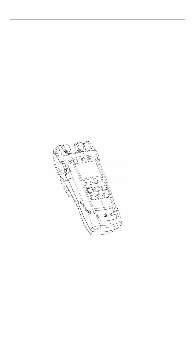
Introducing the PPM-350C PON Power Meter 2
Liquid crystal
display (LCD)DC connector
Keypad
Stand
Shoulder
strap eyelet
Status LEDs
Optical Power Meter (OPM) Operation Mode
3 calibrated wavelengths and up to 40 predefined wavelengths (from 1260 nm
to 1650 nm), each with their own correction factor.
Possible to take reference values for each of the available wavelengths.
Selectable unit (dB or dBm).
Other Useful Features
Automatically shuts down after 10 minutes of idle time (auto-off).
You can manage data directly on the unit (storing, recalling, deleting).
The Handheld Data Transfer (provided on your CD) enables you to create new
threshold sets and correction factors, define your list of favorite wavelengths, as
well as set storage and job options for better data management, or modify
values retrieved from your unit.
You can transfer the data (measurements) directly from your unit to a computer
using the USB port. This will allow you to view them with FastReporter, the
EXFO’s post-processing software.
Page 9

Available Models
Quick reference
label
USB connector
OLT/video port
Serial number
(under the stand)
Battery compartment
(3 alkaline batteries)
ONT port
The PON Power Meter is offered in two wavelength/ ports configurations:
1310 nm (FTTx) / 1490 nm (FTTx/OPM)
1310 nm (FTTx) and 1490 nm/1550 nm (FTTx/OPM)
An optional VFL is also available.
Power Sources
The PON Power Meter operates with the following power sources:
AC adapter (connected to standard power outlet—indoor use only)
AA alkaline batteries (automatically take over if you unplug the AC adapter)
The icon also indicates the battery charge.
IMPORTANT
If the battery level becomes too low, the unit turns itself off.
PPM-350C 3
Page 10

Introducing the PPM-350C PON Power Meter 4
Typical Applications
You can use your PON Power Meter in two modes:
FTTx mode: You can use your PPM-350C PON Power Meter during service
activation (at ONT) or to troubleshoot passive optical networks (at ONT, drop
terminal, fiber distribution hub or CO). This mode allows you to measure two or
three wavelengths simultaneously, depending on the configuration of the unit.
OPM mode: You can use your PPM-350C PON Power Meter to measure the
output power (in dBm) or loss (in dB) using one of the unit’s 40 CWDM
wavelengths available. This mode allows you to measure networks or devices
carrying only one wavelength.
Page 11

Conventions
Before using the product described in this guide, you should understand the
following conventions:
WARNING
Indicates a potentially hazardous situation which, if not avoided,
could result in death or serious injury. Do not proceed unless you
understand and meet the required conditions.
CAUTION
Indicates a potentially hazardous situation which, if not avoided,
may result in minor or moderate injury. Do not proceed unless you
understand and meet the required conditions.
CAUTION
Indicates a potentially hazardous situation which, if not avoided,
may result in component damage. Do not proceed unless you
understand and meet the required conditions.
IMPORTANT
Refers to information about this product you should not overlook.
PPM-350C 5
Page 12
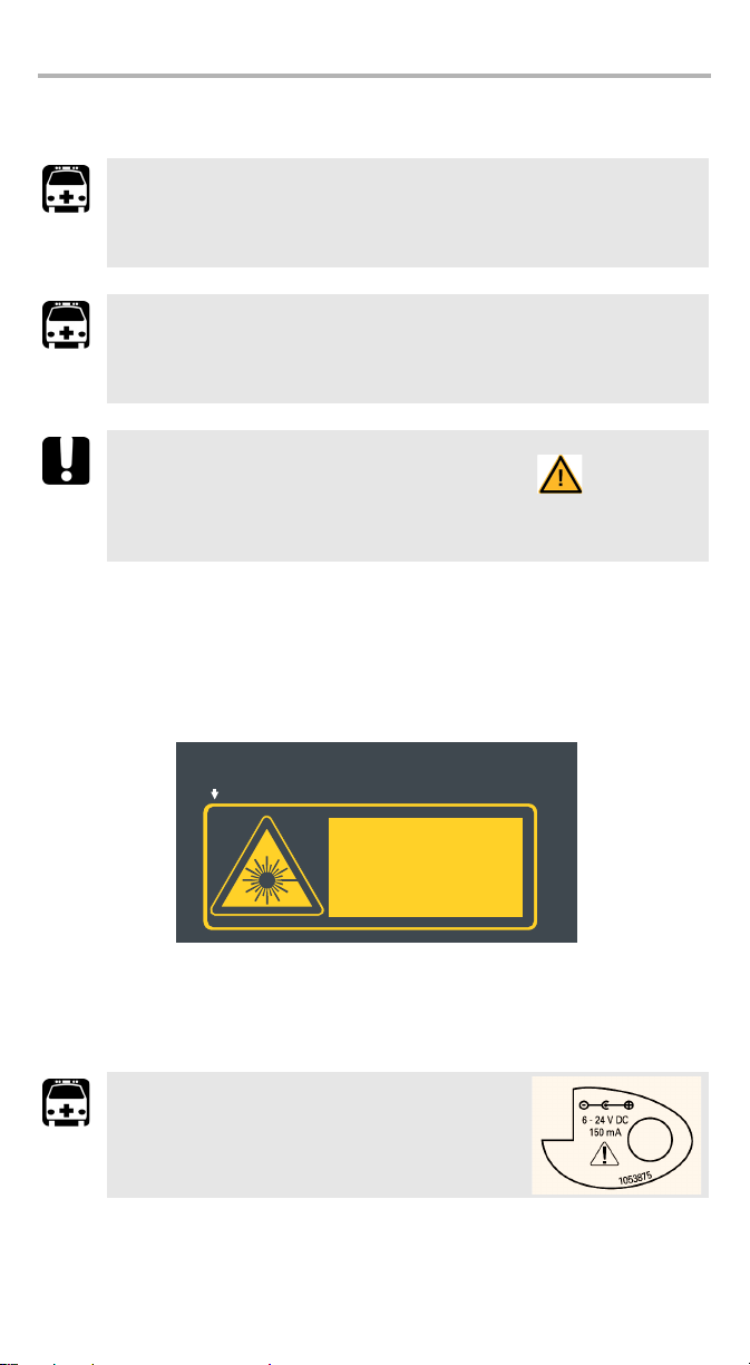
Safety Information 6
This product complies with 21 CFR 1040.10 and 1040.11 except
for deviations pursuant to Laser Notice No.50 dated 2001.
If VFL option is available
QST498C
LASER RADIATION
AVOID DIRECT EYE EXPOSURE
CLASS 3R LASER PRODUCT
IEC 60825-1:1993+A2:2001
21 CFR 1040.10
λ: 650 ±10 nm
P
out
maximum < 5mW (into free space)
2 Safety Information
WARNING
The use of controls, adjustments and procedures other than those
specified herein may result in exposure to hazardous situations or
impair the protection provided by this unit.
WARNING
Do not install or terminate fibers while a laser source is active. Never
look directly into a live fiber and ensure that your eyes are protected
at all times.
IMPORTANT
When you see the following symbol on your unit , make sure
that you refer to the instructions provided in your user
documentation. Ensure that you understand and meet the required
conditions before using your product.
Laser Safety Information (Models with VFL)
Your instrument is a Class 3R laser product in compliance with standards
IEC 60825-1 and 21 CFR 1040.10. It is potentially harmful in direct intrabeam
viewing.
The following label(s) indicate that the product contains a Class 3R source:
The label is affixed at the back of your unit if the VFL option is present.
Electrical Safety Information
WARNING
Use the AC adapter provided with this product
indoors only.
Page 13

Ultra-High-Power™ Safety Information
WARNING
When using high-power live fiber, use protective eyewear and
clothes to avoid contact with light or heat emanating from the
detector port. Refer to safety measures valid in your country for
more information.
To avoid personal injury or damage to your unit, connect high-power
live fiber to the detector port only.
CAUTION
Do not use plastic FOAs when manipulating high-power live fiber.
This will cause the plastic FOAs to melt.
WARNING
If a laser with a power of more than 25 dBm is connected to one of
the ports of the PPM-350C, light may come out from the other port,
even if the protective cap is on. Do not consider that the protective
cap is sufficient protection in such high-power laser cases.
Equipment Ratings
Te mp er at u re
Operation
Storage
Relative humidity %to 95 % non-condensing
Maximum operation
altitude
Pollution degree 2 (unit used inside; connected to AC mains or powered
Overvoltage category II
Power supply rating 6 - 24 V; 150 mA
-10°C to 50°C (14°F to 122°F)
-40 °C to 70 °C (-40 °F to 158 °F)
2000 m (6562 ft)
by batteries)
3 (unit used outside; powered by batteries)
a
b
a. Use the external power supply indoors only.
b. Equipment should be normally protected against exposure to direct sunlight, precipitations and
full wind pressure.
PPM-350C 7
Page 14

Getting Started with Your PON Power Meter 8
3 Getting Started with Your
PON Power Meter
Turning the Unit On and Off
When you turn the PON Power Meter off, it saves the current settings, which
include:
for the FTTx operation: the mode (Pass/Fail or Normal) and threshold set.
for the OPM operation: the unit, reference values, and wavelength.
IMPORTANT
If you remove batteries (and the AC adapter is unplugged), the unit
will turn off without saving the above values.
If batteries are low (and the AC adapter is unplugged), the unit will
save the above values and turn off.
Note: Offset nulling values are always returned to factory settings.
To t u rn t h e un i t o n :
Press . The unit displays EXFO for a few seconds and vertical bars move at the
top of the display, indicating the initialization is in progress. You may use your unit
immediately under normal conditions. The unit uses the settings as they were saved
last time you turned it off.
To turn the unit off:
Hold down a few seconds. The unit saves the current settings automatically.
Page 15
Batteries in use
(with level;
blinking when
weak)
Status; FTTx operation only
Signal (wavelength);
FTTx operation only
Power level
Reference values displayed;
OPM operation only
Display
Auto-off activated
AC adapter plugged in
Units
Storage mode either to save results
or recall settings.
Threshold selection mode activated;
FTTx operation only
Selected wavelength
corresponds to a calibration
wavelength;
OPM operation only
Indicates the presence of “keep-alive”
signal (which prevents
communication loss during periods of
idleness) or any other data packet
Correction factor not
equal to 0 dB
Information fields
that will be stored
PRESS: Turns unit on
Controls auto-off
Exits special modes
HOLD: Turns unit off
PRESS: Accesses the storage
mode; in selection mode, selects
the value.
HOLD: Accesses the data recall
mode; in Recall mode, accesses
the delete item function
PRESS: For FTTX
operation, accesses
threshold selection mode;
for OPM operation,
selects the next
wavelength in the list.
HOLD: For FTTx operation,
displays the current
threshold values.
PRESS: Activates/deactivates Pass/Fail mode
(not possible during nulling, threshold verification,
LEDs/LCD verification)
HOLD: Selects the FTTx or OPM measurement
Keypad
(available only for OPM)
PRESS: Switches between dBm
and dB units
HOLD: Takes the input power as
reference power
PRESS: In selection
mode, goes to the next
value; for OPM
operation, goes to the
next wavelength in the
list
HOLD: If VFL option is
present, changes the
VFL state between OFF,
ON CW and ON 1 Hz
PPM-350C 9
Page 16

Getting Started with Your PON Power Meter 10
Bare metal
(or blue border)
indicates UPC option
Green border
indicates APC
option
2 3 4
Activating Automatic Shutdown (Auto-Off)
When auto-off is activated, the unit will turn itself off
after 10 minutes of idle time.
Auto-off is activated by default when you turn unit on.
To deactivate/reactivate auto-off:
Press .
Installing the EXFO Universal Interface (EUI)
The EUI fixed baseplate is available for connectors with angled (APC) or non-angled
(UPC) polishing. A green border around the baseplate indicates that it is for
APC-type connectors.
To install an EUI connector adapter onto the EUI baseplate:
1. Hold the EUI connector adapter so the dust cap opens downwards.
2. Close the dust cap in order to hold the connector adapter more firmly.
3. Insert the connector adapter into the baseplate.
4. While pushing firmly, turn the connector adapter clockwise on the baseplate to
lock it in place.
Page 17

Cleaning and Connecting Optical Fibers
IMPORTANT
To ensure maximum power and to avoid erroneous readings:
Always clean fiber ends as explained below before inserting
them into the port. EXFO is not responsible for damage or errors
caused by bad fiber cleaning or handling.
Ensure that your patchcord has appropriate connectors. Joining
mismatched connectors will damage the ferrules.
To connect the fiber-optic cable to the port:
1. Inspect the fiber using a fiber inspection microscope. If the fiber is clean,
proceed to connecting it to the port. If the fiber is dirty, clean it as explained
below.
2. Clean the fiber ends as follows:
2a. Gently wipe the fiber end with a lint-free swab dipped in isopropyl alcohol.
2b. Use compressed air to dry completely.
2c. Visually inspect the fiber end to ensure its cleanliness.
3. Carefully align the connector and port to prevent the fiber end from touching the
outside of the port or rubbing against other surfaces.
If your connector features a key, ensure that it is fully fitted into the port’s
corresponding notch.
4. Push the connector in so that the fiber-optic cable is firmly in place, thus
ensuring adequate contact.
If your connector features a screwsleeve, tighten the connector enough to firmly
maintain the fiber in place. Do not overtighten, as this will damage the fiber and
the port.
Note: If your fiber-optic cable is not properly aligned and/or connected, you
will notice heavy loss and reflection.
EXFO uses good quality connectors in compliance with EIA-455-21A standards.
To keep connectors clean and in good condition, EXFO strongly recommends
inspecting them with a fiber inspection probe before connecting them. Failure to do
so will result in permanent damage to the connectors and degradation in
measurements.
PPM-350C 11
Page 18

Getting Started with Your PON Power Meter 12
Threshold/
Select
Nulling Electrical Offsets
Temperature and humidity variations affect the performance of electronic circuits
and optical detectors. Nulling the electrical offsets eliminates these effects. Your
unit has been designed not to require offset nulling under normal operation, but you
should perform it whenever environmental conditions change significantly or when
measuring very low power values.
IMPORTANT
If light reaches the detector when nulling offsets, LIGH appears on
the display and the nulling is not performed. You will need to press a
key to return to the previous display.
Note: Factory-defined values will be reinstated when you turn the unit off.
To perform an offset nulling:
Hold down and a few seconds.
The unit displays NULL and vertical bars move at
the top of the display, indicating the nulling is in
progress.
Note: Keypad is disabled during the operation.
The unit will then return to your previous mode (Pass/Fail or Normal).
Page 19

4 Configuring Thresholds,
Correction Factors,
Wavelength List, and
Storage Details
Your PPM-350C PON Power Meter has been configured by EXFO with predefined
information:
Threshold sets that you use in FTTx mode. Up to 10 sets are available.
A threshold set consists of the number of wavelengths (2 or 3) depending on
your unit. For each wavelength, you can select the pass, warning and fail
criteria.
Correction factors for the FTTx mode and OPM mode. These are set to 0 dB
since they were properly calibrated at EXFO.
Correction factors are added to the measured values. For this reason, once the
correction factors are applied, your PON Power Meter may display “HI” or “LO”,
indicating the power levels are no longer within the unit’s power limits.
If you need to define correction factors of more than 1 dB or less than –1 dB to
compensate for inaccuracies, it may be a good idea to send your PON Power
Meter for recalibration (see Recalibrating the Unit on page 27). This will ensure
the results remain accurate.
A wavelength list consisting of 1310 nm, 1490 nm and 1550 nm for OPM
operations. This list may contain up to 40 wavelengths (from 1260 nm to
1650 nm)
Predefined storage information used in FTTx and OPM operations such as OLT
names, ONT names and LOC ID names.
You may customize these parameters using the Handheld Data Transfer (HHDT)
software provided on your CD.
The Handheld Data Transfer enables you to create new threshold sets and
correction factors, define your list of favorite wavelengths, as well as set storage and
job options for better data management, or modify values retrieved from your PON
Power Meter. You can configure your PPM-350C with up to 32 OLTs, 255 ONTs,
16 LOCs and 32 JOBs. For more information, refer to the Handheld Data Transfer
online help.
IMPORTANT
Thresholds, correction factors, wavelength list, as well as storage
and job options will be transferred to your unit. Previous values will
be lost.
PPM-350C 13
Page 20

Working in FT Tx Mode 14
5 Working in FTTx Mode
You can use this mode during service activation (at ONT) or to troubleshoot passive
optical networks (at ONT, drop terminal, fiber distribution hub or CO). You can
measure two or three wavelengths simultaneously, depending on the configuration
of the unit.
Selecting a Threshold Set
You can select which threshold set will be used to determine the Pass/Warning/Fail
status. Your unit contains up to 10 threshold sets, but only one set can be selected at
a time.
Depending on the model of the unit, a threshold set comprises two or three
wavelengths (1310 and 1490 nm; 1310, 1490, and 1550 nm), each of them having
specific threshold values for pass, warning and fail.
Note: Thresholds are used in Pass/Fail mode only.
You can view thresholds directly on your unit. To modify threshold values, you must
use the Handheld Data Transfer (refer to the Handheld Data Transfer online help).
Page 21

To select a threshold set:
Threshold set number
Threshold set name
Current threshold set indicators
Threshold/
Threshold/
Next
Signal (wavelength)
Threshold/
Threshold/
Next
Select
1. Press . The unit enters the threshold
selection mode and displays the current
threshold set. If the threshold name has more
than 4 characters, it will scroll automatically.
2. Press or to switch between
available threshold sets.
3. If desired, display the Pass/Warning/Fail values of the threshold set as follows:
3a. Hold down for a few seconds. The
unit displays threshold values of the first
wavelength that has not been deactivated.
3b. Press or to switch to the next
wavelength.
Note: If a wavelength has been deactivated via
the Handheld Data Transfer (refer to the
Handheld Data Transfer online help), the
unit displays no threshold values.
3c. Press to return to threshold selection mode.
4. Press to make the displayed threshold set the current one.
The unit returns to Pass/Fail mode.
5. Press to exit without selecting a new threshold set. The unit returns to your
previous mode.
PPM-350C 15
Page 22

Working in FT Tx Mode 16
Pass/Fail Normal
Signal (wavelength)
Power levels (dBm)
Status
LEDs are on:
Green (Pass),
Yellow (Warning), Red (Fail)
When power is outside unit’s power limits
(see Technical Specifications on page 39)
Power levels (dBm only)
Testing in Pass/Fail Mode or in Normal Mode
Pass/Fail mode: status is indicated directly (screen and LEDs). Status is
determined according to the current threshold set (see Selecting a Threshold
Set on page 14).
Normal mode: only the power levels are shown and LEDs are off.
Note: If the result is greater than the Pass threshold, the word Fail and the LED
will flash. If the result is lower than the Fail threshold, the unit will only
display Fail and the LED will not flash.
At startup, the unit is in the same mode that was used during last test session.
Page 23

To test in Pass/Fail or Normal mode:
Test at the premises
Tes t j u mp e r
ONT port
Tes t j u mp e r
OLT/video port
Drop cable
Bulkhead connector
Test at the drop terminal
Tes t j u mp e r
ONT port
Tes t j u mp e r
OLT/video port
Bulkhead connector
Drop cable
ONT port
Tes t j u mp e r
OLT/video port
Splitter’s output pigtail
Bulkhead connector
Te s t ju m pe r
Test at the fiber distribution hub (FDH)
P/F
mode
1. Inspect your fibers and clean them properly if needed (see Cleaning and
Connecting Optical Fibers on page 11 for details).
2. Connect as shown:
3. Tu r n un i t on .
4. If you want to test in Pass/Fail mode:
Ensure that LEDs are on. If not, press .
Ensure that the desired threshold set is selected (see Selecting a Threshold
Set on page 14).
Results are now available.
PPM-350C 17
Page 24

Working in OPM Mode 18
P/F
mode
Threshold/
Next
dBm/dBdBm/
dB
6 Working in OPM Mode
Your unit can also be used as a standard optical power meter (in the OPM mode).
This is particularly useful if you want to measure networks or devices carrying only
one wavelength.
You can measure the output power (in dBm) or loss (in dB) using one of the
unit’s 40 CWDM wavelengths available.
You can select the wavelength that you want to use for your measurements. To
customize the list of available wavelengths, you must use HHDT (refer to the
online help of the HHDT application for more information).
You can set a specific reference value for each wavelength of the list. This
reference value will remain in memory until you store a new one for the same
wavelength.
When you use reference, your unit displays the loss created by the fiber under
test only, since it subtracts a reference value from the measured power.
To perform loss measurements:
1. Clean your fibers properly as explained in Cleaning and Connecting Optical
Fibers on page 11.
2. Connect the fiber to the OLT/video port.
3. Tu r n un i t on .
4. Select the OPM mode, by pressing and holding down a few seconds.
5. Select the test wavelength by pressing
or until the desired wavelength
is displayed.
6. Press to select dB, so that the loss is
expressed in dB.
7. Hold down for a few seconds to take the
reference.
The reference indicator is displayed, showing that the new reference value is
now stored in memory.
Loss measurement is displayed just under the reference value.
8. If desired, you can store the loss measurement in your unit (see Storing Data on
page 19).
Page 25

7 Managing Test Results
Store/
Select
OLT ID
number
OLT name
Next
Store/
Select
Next
Store/
Select
Next
Store/
Select
You can save up to 1000 results (FTTx or OPM) in your unit. You can recall this data
later according to the storage configuration you have set. It is also possible to delete
data directly from your unit.
If you prefer, you can also transfer your data from your unit to a computer using a
USB cable.
Storing Data
Using the Handheld Data Transfer (HHDT) application, you can set storage
configurations and then upload them to your unit using a USB cable. Refer to the
Handheld Data Transfer documentation for more information on uploading
configurations.
You can have configurations using the following modes selected by HHDT:
OLT and ONT IDs, with different locations.
Job, where the OLT and ONT are grouped with different locations.
To store data in OLT mode:
1. Press to access the data storage menu. The data you have selected is
temporarily stored to allow you to enter further information.
2. Press to access the available OLT
values. The OLT name is displayed next
to the Loc. indicator.
3. Press to select the OLT and switch
to the ONT selection.
4. Press to access the available ONT.
5. Press to select the ONT and switch to the Loc
ID selection.
6. Press to access the available Loc. IDs.
7. Press to select the location or to exit the
storage mode.
The data is stored. The Store indicator is highlighted to
show that the operation is complete.
PPM-350C 19
Page 26

Managing Test Results 20
Store/
Select
Job ID
number
Job name
Next
Store/
Select
Store/
Select
To store data in Job mode:
1. Press to access the data storage menu. The data you have selected is
temporarily stored to allow you to enter further information.
2. Press to access the available Job
ID values.
3. Press to select the job and access
the available Loc. IDs.
4. Press to select the location or to exit the
storage mode.
The data is stored. The Store indicator is highlighted to
show that the operation is complete.
Page 27

Recalling Data
Store/
Select
OLT ID
number
OLT name
Next
Store/
Select
Next
Store/
Select
Next
Store/
Select
Next
Store/
Select
Next
According to the storage configuration you have set using the Handheld Data
Transfer application, you can recall data you have previously stored.
You can recall files according to the following modes, depending on how your unit
was set:
OLT and ONT IDs, with different locations.
Job, where the OLT and ONT are grouped in different locations.
To recall data in OLT mode:
1. Press and hold down for a few seconds to access the data recall menu.
2. Press to access the available OLT
values. The OLT name is displayed next
to the Loc. indicator.
3. Press to select the OLT and switch to the ONT selection.
4. Press to access the available ONT.
5. Press to select the ONT or to exit the recall
mode.
The data is recalled. Press to go through the data
with the same OLT and ONT values.
To recall data in Job mode:
1. Press and hold down for a few seconds to access the data recall menu.
2. Press to access the available Job ID values.
3. Press to select the job or to exit the recall
mode.
The data is recalled. Press to go through the data
with the same Job ID values.
PPM-350C 21
Page 28

Managing Test Results 22
Store/
Select
Store/
Select
Store/
Select
Deleting Data
You can delete unwanted data directly from the unit when viewing your stored data.
To delete data:
1. Press and hold down for a few seconds to access the data recall menu.
2. Select the data you want to delete.
3. Press and hold down for a few seconds once again.
4. The del CONF (delete confirm) message appears.
5. Press to confirm your choice, or to cancel.
Transferring Data to a Computer
Using an appropriate USB cable and the Handheld Data Transfer software, you can
transfer saved data from your unit to a computer. This way, you can free memory
space, perform better analyses on your data and create reports.
To transfer data to a computer:
1. Using a USB cable, connect your unit to an available USB port of the computer.
2. Turn on both the computer and your handheld unit. Connect your unit to a
power outlet to ensure that your unit will remain on during the transfer.
3. On the computer, start the Handheld Data Transfer application and start the
operation.
The unit displays “REM” and temporarily deactivates the keyboard and auto-off.
Note: For details about setting up the software and transferring data, refer to
the Handheld Data Transfer online help.
IMPORTANT
Transferred data is not automatically deleted from your unit.
Page 29

8 Identifying Fiber Faults
Next
Next
Visually
Note: This feature is available only if your unit is equipped with a VFL port.
The visual fault locator (VFL) helps you identify bends, faulty connectors, splices
and other causes of signal loss.
From its dedicated port, the VFL emits a red signal which becomes visible at the
location of a fault on the fiber. This signal can be continuous (the default) or blinking
(1 Hz).
WARNING
When the VFL is active, the VFL port emits visible laser radiation.
Avoid exposure and do not stare directly into the beam. Ensure that
any unused port is properly protected with a cap.
When the VFL is on, the rightmost status LED will also be on.
To activate the VFL and inspect a fiber:
1. Connect the fiber under test to the VFL port (see Cleaning and Connecting
Optical Fibers on page 11).
2. Press and hold down for a few seconds to switch between ON CW
(continuous signal) and ON 1HZ (blinking signal).
3. Without looking directly into the beam, examine the fiber. If light is coming out
of the rubber jacket or on the side of the ferrule, the fiber is defective.
4. Deactivate the VFL by pressing and holding down for a few seconds to
switch between the signals (ON CW and ON 1HZ), until you reach OFF.
PPM-350C 23
Page 30

Maintenance 24
9 Maintenance
To help ensure long, trouble-free operation:
Always inspect fiber-optic connectors before using them and clean them if
necessary.
Keep the unit free of dust.
Clean the unit casing and front panel with a cloth slightly dampened with water.
Store unit at room temperature in a clean and dry area. Keep the unit out of
direct sunlight.
Avoid high humidity or significant temperature fluctuations.
Avoid unnecessary shocks and vibrations.
If any liquids are spilled on or into the unit, turn off the power immediately,
disconnect from any external power source, remove the batteries and let the
unit dry completely.
WARNING
The use of controls, adjustments and procedures other than those
specified herein may result in exposure to hazardous situations or
impair the protection provided by this unit.
Page 31

Cleaning EUI Connectors
Push
Tur n
Pull
3
4
5
Regular cleaning of EUI connectors will help maintain optimum performance. There
is no need to disassemble the unit.
IMPORTANT
If any damage occurs to internal connectors, the module casing will
have to be opened and a new calibration will be required.
To clean EUI connectors:
1. Remove the EUI from the instrument to expose the connector baseplate and
ferrule.
2. Moisten a 2.5 mm cleaning tip with one drop of isopropyl alcohol (alcohol may
leave traces if used abundantly).
3. Slowly insert the cleaning tip into the EUI adapter until it comes out on the other
side (a slow clockwise rotating movement may help).
4. Gently turn the cleaning tip one full turn, then continue to turn as you withdraw
it.
PPM-350C 25
Page 32

Maintenance 26
5. Repeat steps 3 to 4 with a dry cleaning tip.
Note: Make sure you don’t touch the soft end of the cleaning tip.
6. Clean the ferrule in the connector port as follows:
6a. Deposit one drop of isopropyl alcohol on a lint-free wiping cloth.
IMPORTANT
Since isopropyl alcohol is not absolutely pure, it may leave residues
if used abundantly or left to evaporate (about 10 seconds).
Avoid contact between the tip of the bottle and the wiping cloth,
dry the surface quickly, and use a bottle that distributes only a drop
of alcohol at a time.
6b. Gently wipe the connector and ferrule.
6c. With a dry lint-free wiping cloth, gently wipe the same surfaces to ensure
that the connector and ferrule are perfectly dry.
6d. Verify connector surface with a portable fiber-optic microscope (for
example, EXFO’s FOMS) or fiber inspection probe (for example, EXFO’s
FIP).
WARNING
Verifying the surface of the connector WHILE THE UNIT IS ACTIVE
WILL result in permanent eye damage.
7. Put the EUI back onto the instrument (push and turn clockwise).
8. Throw out cleaning tips and wiping cloths after one use.
Page 33

Replacing Disposable Alkaline Batteries
+
+
+
Your unit requires three AA alkaline batteries.
Note: The provided AC adapter is not a charger.
To replace disposable alkaline batteries:
1. Turn off the unit (if the AC adapter is plugged in, you
may replace batteries while unit is on).
2. Open the battery compartment door located at the
back of the unit.
3. Replace batteries, respecting the polarity as shown.
4. Close the battery compartment door.
WARNING
Do not throw batteries into fire or water and do not short-circuit
the batteries’ electrical contacts.
WARNING
Using the wrong type of battery can lead to product damage,
overheating, or even explosion.
CAUTION
EXFO guarantees the specifications and viability of the products
ONLY if they are used with chargers provided by EXFO.
Recalibrating the Unit
Manufacturing and service center calibrations are based on the ISO/IEC 17025
Standard, which states that calibration documents must not contain a
recommended calibration interval, unless this has been previously agreed upon
with the customer.
Validity of specifications depends on operating conditions. For example, the
calibration validity period can be longer or shorter depending on the intensity of use,
environmental conditions and unit maintenance. You should determine the
adequate calibration interval for your unit according to your accuracy requirements.
Under normal use, EXFO recommends calibrating your unit every three years.
Note: The FlexCare warranty program includes Calibration/Verification
PPM-350C 27
packages (see Service and Repairs on page 37).
Page 34

Maintenance 28
Yea rMonth/Day
Threshold/
Next
P/F
mode
Threshold/
To view the last calibration date:
1. Press and hold down and press at the
same time. The unit displays the main embedded
software version.
2. Press to display the calibration date of the unit.
3. Press to return to your previous mode.
Verifying the Integrity of User Information in Memory
You can verify the integrity of the memory to ensure that your unit will function
normally for threshold sets, correction factors, wavelength lists and storage
information.
If a problem is detected, error code 9, 10, or 12 will be displayed. If you turn the unit
off without correcting the problem, the error code will be displayed once the unit is
turned on again. For more information, see Error Codes and Descriptions on
page 31.
To verify memory integrity:
Hold down and a few seconds. The
unit displays CHKS and vertical bars move at the top of
the display, indicating the verification is in progress.
Note: Keypad is disabled during this operation.
The unit will then return to your previous mode.
Page 35

Verifying the LEDs and LCD
P/F
mode
You can verify that the LEDs function normally and that the screen can display all the
elements properly. The unit must be in Pass/Fail or Normal mode to perform the
verification.
To verify the LEDs and LCD:
1. Hold down and a few seconds. The unit
displays TEST and vertical bars move at the top of
the display, indicating the verification is in progress.
The three LEDs will light up briefly in the following
order: green, yellow, red. Once LEDs are turned off,
all the screen segments will be displayed at the
same time, allowing you to verify them.
Note: Keypad is disabled during the operation.
2. Press any key to return to your previous mode.
Recycling and Disposal (Applies to European Union Only)
For complete recycling/disposal information as per European Directive WEEE
2002/96/EC, visit the EXFO Web site at www.exfo.com/recycle.
PPM-350C 29
Page 36

Troubleshooting 30
P/F
mode
10 Troubleshooting
Solving Common Problems
Problem Possible Cause Solution
One of the LEDs remains
off.
OR
One of the LEDs remains
green or red even if the
status is Warning.
Pressing the button
does not activate Pass/Fail
mode.
LED is burnt.
Verify LEDs (see Verifying
the LEDs and LCD on
page 29).
Unit is currently
nulling offsets,
verifying thresholds or
verifying LEDs and
LCD.
The current threshold
set contains an
unusable (corrupted)
value.
No threshold sets have
been defined.
Contact EXFO.
Let the unit complete
the operation.
If the unit was
verifying LEDs and
LCD, press any key to
return to your previous
mode (Pass/Fail or
Normal).
See Error Codes and
Descriptions on
page 31.
See Error Codes and
Descriptions on
page 31.
Page 37

Problem Possible Cause Solution
The threshold set name is
not displayed correctly.
In Pass/Fail mode,
impossible to see all
wavelengths and some of
the LEDs are off.
Name contains characters
that your unit cannot
display. Unsupported
characters are replaced
with dashes, spaces or
“+”.
At least one signal is
deactivated (see Selecting
a Threshold Set on
page 14).
Rename the threshold set
using only supported
characters:
0 through 9
A through Z (both
lowercase and
uppercase)
- (dash) + / . < = > ?
[ \ ] _ (underscore)
and space
For more information on
renaming threshold sets,
see Configuring
Thresholds, Correction
Factors, Wavelength List,
and Storage Details on
page 13.
Reactivate the signal (see
Configuring Thresholds,
Correction Factors,
Wavelength List, and
Storage Details on
page 13).
Error Codes and Descriptions
ER: error code displayed until you press a key.
WR: warning code displayed for 3 seconds, then unit returns to normal.
Error
Code
EMPT Storage memory is empty, there is
nothing to recall.
FULL Storage memory is full. Free some storage space by
LIGH Light detected while nulling offsets.
Nulling is not performed.
ER 9 Configuration for storage information
is not usable (corruption problem).
PPM-350C 31
Description Solution
Store at least one measurement
before going in recall mode.
deleting measurements.
Correctly place protective cap on
ports, then retry. If the problem
persists, contact EXFO.
Download new storage
information (see Configuring
Thresholds, Correction Factors,
Wavelength List, and Storage
Details on page 13).
Page 38

Troubleshooting 32
Error
Code
Description Solution
ER 10 Configuration for wavelength list and
correction factors is not usable
(corruption problem).
ER 12/16 Threshold values are not usable
(corruption problem).
Would occur:
during unit initialization
after threshold verification (see
Verifying the Integrity of User
Information in Memory on
page 28)
after threshold set selection
ER 13 EEPROM corrupted (would occur
during unit initialization).
ER 17 No signal is activated for the selected
threshold.
The error is displayed again if you try
to activate the threshold. You must
enter the threshold selection mode to
select another threshold.
This error can be displayed at startup if
no threshold signal is selected when
shutting down the unit.
The threshold signal activation is done
through the threshold download
application.
WR 23 No threshold sets have been defined.
Pass/Fail mode cannot be activated.
WR 24 Date and time of the real-time clock
are not valid.
Download new wavelength list
and correction factors (see
Configuring Thresholds,
Correction Factors, Wavelength
List, and Storage Details on
page 13).
Download new threshold sets to
your unit. For more information,
see Configuring Thresholds,
Correction Factors, Wavelength
List, and Storage Details on
page 13.
Unit must be recalibrated.
Contact EXFO.
Enter the threshold selection
mode Activate another
threshold.
Download new threshold sets to
your unit. For more information,
see Configuring Thresholds,
Correction Factors, Wavelength
List, and Storage Details on
page 13.
Use HHDT to transfer date and
time of the real-time clock by
configuring the PPM-350C.
If the problem persists, you may
have to change the real-time
clock battery. Contact EXFO for
details.
Page 39

Contacting the Technical Support Group
Threshold/
To obtain after-sales service or technical support for this product, contact EXFO at
one of the following numbers. The Technical Support Group is available to take your
calls from Monday to Friday, 8:00 a.m. to 7:00 p.m. (Eastern Time in North America).
For detailed information about technical support, visit the EXFO Web site at
www.exfo.com.
Technical Support Group
400 Godin Avenue
Quebec (Quebec) G1M 2K2
CANADA
To accelerate the process, please have information such as the name and the serial
number (see the product identification label), as well as a description of your
problem, close at hand.
You may also be requested to provide the embedded software’s version numbers.
To display the embedded software version:
1. Hold down and press at the same time. The unit displays the main
software version.
2. Press to return to your previous mode.
1 866 683-0155 (USA and Canada)
Tel.: 1 418 683-5498
Fax: 1 418 683-9224
support@exfo.com
PPM-350C 33
Page 40

Troubleshooting 34
Transportation
Maintain a temperature range within specifications when transporting the unit.
Transportation damage can occur from improper handling. The following steps are
recommended to minimize the possibility of damage:
Pack the unit in its original packing material when shipping.
Avoid high humidity or large temperature fluctuations.
Keep the unit out of direct sunlight.
Avoid unnecessary shocks and vibrations.
Page 41

11 Warranty
General Information
EXFO Inc. (EXFO) warrants this equipment against defects in material and
workmanship for a period of three years from the date of original shipment. EXFO
also warrants that this equipment will meet applicable specifications under normal
use.
During the warranty period, EXFO will, at its discretion, repair, replace, or issue
credit for any defective product should the equipment need to be repaired. If the
equipment is sent back for verification of calibration during the warranty period and
found to meet all published specifications, EXFO will charge standard calibration
fees.
IMPORTANT
The warranty can become null and void if:
unit has been tampered with, repaired, or worked upon by
unauthorized individuals or non-EXFO personnel.
warranty sticker has been removed.
case screws, other than those specified in this guide, have been
removed.
case has been opened, other than as explained in this guide.
unit serial number has been altered, erased, or removed.
unit has been misused, neglected, or damaged by accident.
THIS WARRANTY IS IN LIEU OF ALL OTHER WARRANTIES EXPRESSED, IMPLIED,
OR STATUTORY, INCLUDING, BUT NOT LIMITED TO, THE IMPLIED WARRANTIES OF
MERCHANTABILITY AND FITNESS FOR A PARTICULAR PURPOSE. IN NO EVENT
SHALL EXFO BE LIABLE FOR SPECIAL, INCIDENTAL, OR CONSEQUENTIAL
DAMAGES.
Liability
EXFO shall not be liable for damages resulting from the use of the product, nor shall
be responsible for any failure in the performance of other items to which the
product is connected or the operation of any system of which the product may be a
part.
EXFO shall not be liable for damages resulting from improper usage or unauthorized
modification of the product, its accompanying accessories and software.
PPM-350C 35
Page 42

Warranty 36
Exclusions
EXFO reserves the right to make changes in the design or construction of any of its
products at any time without incurring obligation to make any changes whatsoever
on units purchased. Accessories, including but not limited to fuses, pilot lamps,
batteries and universal interfaces (EUI) used with EXFO products are not covered by
this warranty.
This warranty excludes failure resulting from: improper use or installation, normal
wear and tear, accident, abuse, neglect, fire, water, lightning or other acts of nature,
causes external to the product or other factors beyond the control of EXFO.
IMPORTANT
EXFO will charge a fee for replacing optical connectors that were
damaged due to misuse or bad cleaning.
Certification
EXFO certifies that this equipment met its published specifications at the time of
shipment from the factory.
Page 43

Service and Repairs
EXFO commits to providing product service and repair for five years following the
date of purchase.
To send any equipment for service or repair:
1. Call one of EXFO’s authorized service centers (see EXFO Service Centers
Worldwide on page 38). Support personnel will determine if the equipment
requires service, repair, or calibration.
2. If equipment must be returned to EXFO or an authorized service center, support
personnel will issue a Return Merchandise Authorization (RMA) number and
provide an address for return.
3. If possible, back up your data before sending the unit for repair.
4. Pack the equipment in its original shipping material. Be sure to include a
statement or report fully detailing the defect and the conditions under which it
was observed.
5. Return the equipment, prepaid, to the address given to you by support
personnel. Be sure to write the RMA number on the shipping slip. EXFO will
refuse and return any package that does not bear an RMA number.
Note: A test setup fee will apply to any returned unit that, after test, is found to
meet the applicable specifications.
After repair, the equipment will be returned with a repair report. If the equipment is
not under warranty, you will be invoiced for the cost appearing on this report. EXFO
will pay return-to-customer shipping costs for equipment under warranty. Shipping
insurance is at your expense.
Routine recalibration is not included in any of the warranty plans. Since
calibrations/verifications are not covered by the basic or extended warranties, you
may elect to purchase FlexCare Calibration/Verification Packages for a definite
period of time. Contact an authorized service center (see EXFO Service Centers
Worldwide on page 38).
PPM-350C 37
Page 44

Warranty 38
EXFO Service Centers Worldwide
If your product requires servicing, contact your nearest authorized service center.
EXFO Headquarters Service Center
400 Godin Avenue
Vanier (Quebec) G1M 2K2
CANADA
EXFO Europe Service Center
Omega Enterprise Park, Electron Way
Chandlers Ford, Hampshire S053 4SE
ENGLAND
EXFO Telecom Equipment
(Shenzhen) Ltd.
3rd Floor, Building 10,
Yu Sheng Industrial Park (Gu Shu Crossing),
No. 467,
National Highway 107,
Xixiang, Bao An District,
Shenzhen, China, 518126
1 866 683-0155 (USA and Canada)
Tel.: 1 418 683-5498
Fax: 1 418 683-9224
support@exfo.com
Tel.: +44 2380 246810
Fax: +44 2380 246801
support.europe@exfo.com
Tel: +86 (755) 2955 3100
Fax: +86 (755) 2955 3101
support.asia@exfo.com
Page 45

A Technical Specifications
Specifications
a
FTTx MODE
PPM-352C PPM-353C
Power measurement range—pass zone for continuous data stream (dBm)
1310 nm 8 to –40 8 to –40
1490 nm 12 to –40 12 to –40
1550 nm 25 to –40 N/A
Burst measurement capability CO to ONT CO to ONT
Burst measurement range
b
(dBm)
1310 nm 8 to –30 8 to –30
ORL
e
(dB)
1550 nm 55 55
Pass-through insertion loss
b
(dB) 1.5 1.5
Spectral passband (nm)
1310 nm 1260 to 1360 1260 to 1360
1490 nm 1480 to 1500 1480 to 1500
1550 nm 1539 to 1565 1539 to 1565
Power uncertainty
b, c, d
(dB) 0.5 0.5
Calibrated wavelengths (nm) 1310/1490/1550 1310/1490
Threshold sets 10 configurable threshold sets 10 configurable threshold sets
with threshold naming with threshold naming
GENERAL SPECIFICATIONS
Size (H x W x D) 195 mm x 100 mm x 57 mm ( 7 11/16 in x 4 in x 2 1/4 in)
Weight
f
0.4 kg (0.9 lb)
Temperature
Operating –10 °C to 50 °C (14 °F to 122 °F)
Storage
f
–40 °C to 70 °C (–40 °F to 158 °F)
Relative humidity 0 % to 95 % non-condensing
Autonomy
b
(hours)
FTTx mode (burst) 35
OPM mode (CW) 80
Number of ports 2
Warranty and recommended calibration interval (years)
g
3
Notes
a. At room temperature.
b. Typical.
c. Around –7 dBm, CW.
d. At calibrated wavelengths.
e. For APC connectors.
f. Without batteries.
g. Excluding connector wear.
CLASS 3R WITH VFL OPTION
IMPORTANT
The following technical specifications can change without notice.
The information presented in this section is provided as a reference
only. To obtain this product’s most recent technical specifications,
visit the EXFO Web site at www.exfo.com.
PPM-350C 39
Page 46

NOTICE
抩⛙
CHINESE REGULATION ON RESTRICTION OF HAZARDOUS SUBSTANCES
₼⦌␂ℝ☀⹂䓸德棟Ⓟ䤓屓⸩
NAMES AND CONTENTS OF THE TOXIC OR HAZARDOUS SUBSTANCES OR ELEMENTS
CONTAINED IN THIS EXFO PRODUCT
▔⚺⦷㦻 EXFO ℶ❐₼䤓㦘㹡㦘⹂䓸德㒥⏒侯䤓⚜䱿✛⚺摞
MARKING REQUIREMENTS
㪖㽷尐㻑
O
Indicates that this toxic or hazardous substance contained in all of the homogeneous
materials for this part is below the limit requirement in SJ/T11363-2006
嫷䯉年㦘㹡㦘⹂䓸德⦷年捷ↅ㓏㦘⧖德㧟㠨₼䤓⚺摞⧖⦷ SJ/T11363-2006 㪖屓⸩䤓棟摞尐
㻑ⅴₚᇭ
X
Indicates that this toxic or hazardous substance contained in at least one of the
homogeneous materials used for this part is above the limit requirement in SJ/T11363-2006
嫷䯉年㦘㹡㦘⹂䓸德咂⺠⦷年捷ↅ䤓㩟⧖德㧟㠨₼䤓⚺摞怔⒉ SJ/T11363-2006 㪖屓⸩䤓
棟摞尐㻑ᇭ
Par t Na me
捷ↅ⚜䱿
Toxic or hazardous Substances and Elements
㦘㹡㦘⹂䓸德✛⏒侯
Lead
杔
(Pb)
Mercury
㻭
(Hg)
Cadmium
椣
(Cd)
Hexavalent
Chromium
⏼ↆ杻
(Cr VI)
Pol yb ro mi na te d
biphenyls
⮩䅃勣啾
(PBB)
Pol yb r om in at ed
diphenyl ethers
⮩䅃ℛ啾搩
(PBDE)
Enclosure
⮥⮂
OO O O O O
Electronic and
electrical
sub-assembly
䟄✛䟄兓ↅ
XO X O X X
Optical
sub-assembly
a
⏘ⷵ兓ↅ
a
a. If applicable.
Ⱁ㨫抑䞷ᇭ
XO O O O O
Mechanical
sub-assembly
a
㧉㬿兓ↅ
a
OO O O O O
Pro duct
ℶ❐
Environmental protection use period (years)
䘾⬒≬㔳∎䞷㦮棟 ( )
Logo
㪖㉦
This Exfo product
㦻 EXFO ℶ❐
10
Battery
a
䟄㻯
a
a. If applicable.
Ⱁ㨫抑䞷ᇭ
5
Page 47

P/N: 1063122
CORPORATE
HEADQUARTERS
www.EXFO.com · info@exfo.com
400 Godin Avenue Quebec (Quebec) G1M 2K2 CANADA
Tel.: 1 418 683-0211 · Fax: 1 418 683-2170
EXFO AMERICA 3400 Waterview Parkway
EXFO EUROPE Omega Enterprise Park,
EXFO ASIA-PACIFIC 100 Beach Road,
EXFO CHINA Beijing Global Trade Center,
EXFO SERVICE
ASSURANCE
EXFO NETHAWK Elektroniikkatie 2 FI-90590 Oulu, FINLAND
TOLL-FREE (USA and Canada) 1 800 663-3936
© 2012 EXFO Inc. All rights reserved.
Printed in Canada (2012-06)
Suite 100
Electron Way
#22-01/03 Shaw Tower
Tower C, Room 1207,
36 North Third Ring Road
East, Dongcheng District
270 Billerica Road Chelmsford MA, 01824 USA
Richardson, TX 75080 USA
Tel.: 1 972-761-927 · Fax: 1 972-761-9067
Chandlers Ford, Hampshire S053 4SE ENGLAND
Tel.: +44 2380 246810 · Fax: +44 2380 246801
SINGAPORE 189702
Tel.: +6563338241 · Fax: +6563338242
Beijing 100013 P. R. CHINA
Tel.: +86 (10) 5825 7755
Fax: +86 (10) 5825 7722
Tel.: 1 978 367-5600 · Fax: 1 978 367-5700
Tel.: +358 (0) 403 010 300
Fax: +358 (0) 8 564 520 3
 Loading...