

Page 1

USER GUIDE
PON POWER METER
PPM-350B
NETWORK TESTING
Advanced Test Equipment Rentals
www.atecorp.com 800-404-ATEC (2832)
®
E
s
t
a
b
l
i
s
h
e
d
1
9
8
1
Page 2

ii
Copyright © 2006 EXFO Electro-Optical Engineering Inc. All rights reserved. No part
of this publication may be reproduced, stored in a retrieval system or transmitted in
any form, be it electronically, mechanically, or by any other means such as
photocopying, recording or otherwise, without the prior written permission of EXFO
Electro-Optical Engineering Inc. (EXFO).
Information provided by EXFO is believed to be accurate and reliable. However, no
responsibility is assumed by EXFO for its use nor for any infringements of patents or
other rights of third parties that may result from its use. No license is granted by
implication or otherwise under any patent rights of EXFO.
EXFO’s Commerce And Government Entities (CAGE) code under the North Atlantic
Treaty Organization (NATO) is 0L8C3.
The information contained in this publication is subject to change without notice.
Trademarks
EXFO’s trademarks have been identified as such. However, the presence or
absence of such identification does not affect the legal status of any trademark.
Units of Measurement
Units of measurement in this publication conform to SI standards and practices.
Patents
The PPM-350B is the subject of International Patent Appln. No. WO 2005/036783;
EXFO’s Universal Interface is protected by US patent 6,612,750.
Page 3

PPM-350B iii
Contents
Certification Information ................................................................................. iv
1 Introducing the PPM-350B PON Power Meter ......................... 1
Main Features ................................................................................................... 1
Available Models .............................................................................................. 3
Power Sources .................................................................................................. 3
Typical Applications .......................................................................................... 3
2 Safety Information ................................................................... 4
Electrical Safety Information ............................................................................. 4
Conventions ...................................................................................................... 4
3 Getting Started with Your PPM-350B PON Power Meter ........ 5
Turning the Unit On and Off ............................................................................. 5
Activating Automatic Shutdown (Auto-Off) ...................................................... 6
Installing the EXFO Universal Interface (EUI) ..................................................... 7
Cleaning and Connecting Optical Fibers ........................................................... 8
4 Configuring Thresholds and Correction Factors ..................... 9
5 Testing with Your PPM-350B PON Power Meter .................... 10
Nulling Electrical Offsets ................................................................................. 10
Viewing Correction Factors ............................................................................. 11
Selecting a Threshold Set ................................................................................11
Testing in Pass/Fail Mode or in Normal Mode .................................................. 13
Measuring Loss Between Two Points ............................................................... 16
6 Maintenance ............................................................................ 18
Cleaning EUI Connectors ................................................................................18
Replacing Disposable Alkaline Batteries .......................................................... 20
Recalibrating the Unit ..................................................................................... 20
Verifying Thresholds ....................................................................................... 21
Verifying the LEDs and LCD ............................................................................. 21
Recycling and Disposal (Applies to European Union Only) .............................. 22
7 Troubleshooting ...................................................................... 23
Solving Common Problems ............................................................................. 23
Error Codes and Descriptions .......................................................................... 24
Contacting the Technical Support Group ........................................................ 25
Finding Information on the EXFO Web Site .................................................... 26
Transportation ................................................................................................ 26
8 Warranty .................................................................................. 27
General Information ....................................................................................... 27
Liability ........................................................................................................... 27
Exclusions ....................................................................................................... 28
Certification .................................................................................................... 28
Service and Repairs ......................................................................................... 29
EXFO Service Centers Worldwide .................................................................... 30
A Technical Specifications .......................................................... 31
Page 4
Certification Information iv
Certification Information
F.C.C. Information
Electronic test equipment is exempt from Part 15 compliance (FCC) in the United
States. However, compliance verification tests are systematically performed on
most EXFO equipment.
Information
Electronic test equipment is subject to the EMC Directive in the European Union.
The EN61326 standard prescribes both emission and immunity requirements for
laboratory, measurement, and control equipment. This unit has undergone
extensive testing according to the European Union Directive and Standards.
Application of Council Directive(s): 73/23/EEC - The Low Voltage Directive
89/336/EEC - The EMC Directive
Manufacturer’s Name: EXFO ELECTRO-OPTICAL ENG.
Manufacturer’s Address: 400 Godin Avenue
Vanier, Québec
Canada G1M 2K2
(418) 683-0211
Equipment Type/Environment: Industrial Scientific Equipment
Trade Name/Model No.: PPM-350B PON Power Meter
Standard(s) to which Conformity is Declared:
EN 61326:
1997/ A2:
2001
Electrical Equipment for Measurement, Control and Laboratory
Use - EMC Requirements
EN 55022:
1998/ A1:
2000
Limits and methods of measurement of radio disturbance
characteristics of information technology equipment
I, the undersigned, hereby declare that the equipment specified above conforms to the above Directive and
Standards.
Manufacturer
Signature:
Full Name: Stephen Bull, E. Eng
Position: Vice-President Research and
Development
Address: 400 Godin Avenue Vanier, Quebec,
Canada
Date: September 15, 2004
DECLARATION OF CONFORMITY
Page 5

PPM-350B 1
1 Introducing the PPM-350B
PON Power Meter
The PPM-350B PON Power Meter was designed to suit FTTP testing needs and to be
easy to use for people who are not necessarily familiar with fiber optics.
Main Features
Details
1-port
Models
2-port
Models
Supports:
³ 1310 nm (ONT)
³ 1490 nm (OLT)
³ 1550 nm (video)
On 2-port models,
³ Port 1: 1310 nm (ONT)
³ Port 2: 1490 nm (OLT)/
1550 nm (video)
XX
Pass-through device (spy
mode): does not block
communication between
ONT and OLT
X
Allows triple-play testing
(voice, video and data)
XX
Measures each signal
independently
³ Optical network terminal
(ONT): 1310 nm
³ Central office (CO): 1490 and
1550 nm
XX
Measures optical power of
any type of signal
³ Continuous (e.g., TV signal at
1550 nm)
³ Framed (e.g., ATM, Ethernet at
1490 nm or 1310 nm)
³ All baud rates (e.g., 155 Mbps,
1 Gpps; synchronous or
asynchronous)
X
X
X
X
X
X
Measures all signals
simultaneously
Only way to measure ONT signal
(ONT does not transmit when
disconnected)
X
Features visual Pass/Fail
indicators
³ One indicator (LED) per
wavelength
³ All 3 signal status are displayed
simultaneously
XX
X
Displays all power levels
simultaneously
X
Page 6
Introducing the PPM-350B PON Power Meter 2
Contains up to 10 different
threshold sets
³ You can select any of the
predefined threshold sets
³ You can configure thresholds
on a computer and transfer
them to your PPM-350B PON
Power Meter via RS-232
XX
Automatically shuts down
after 10 minutes of idle
time (auto-off)
XX
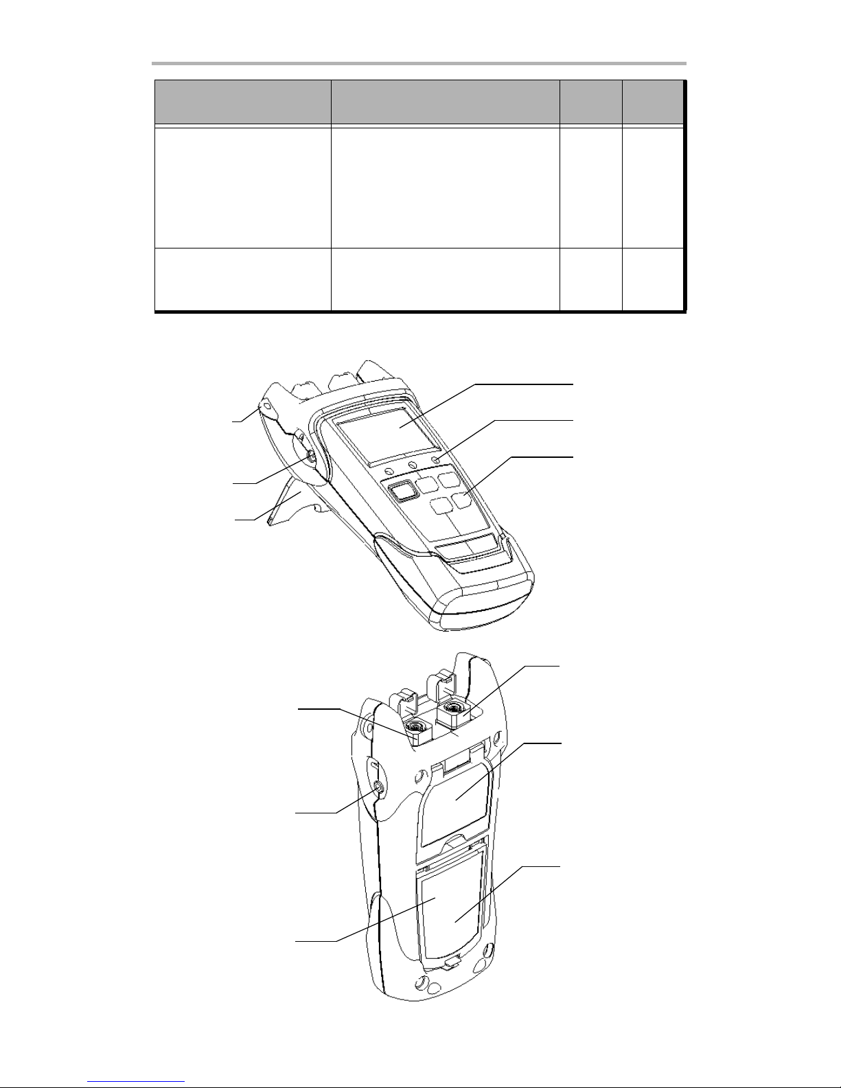
Details
1-port
Models
2-port
Models
Liquid crystal
display (LCD)
DC connector
Keypad
Stand
Shoulder
strap eyelet
Status LEDs
Quick reference
label
RS-232 connector
On 1-port models:
ONT and OLT/video port
On 2-port models:
OLT/video port
Serial number
(under the stand)
Battery compartment
(3 alkaline batteries)
ONT port (on 2-port
models only)
Page 7

PPM-350B 3
Available Models
The PPM-350B PON Power Meter is offered in one- and two-port configurations with
normal or extended measurement range. The extended range allows testing at the
central office and before the splitter.
Some models support relative-power measurement allowing you to measure loss
between two locations.
Power Sources
The PPM-350B PON Power Meter operates with the following power sources:
³ AC adapter (connected to standard power outlet—indoor use only)
³ AA alkaline batteries (automatically take over if you unplug the AC adapter)
The icon also indicates the battery charge.
Typical Applications
You can use your PPM-350B PON Power Meter during service activation (at ONT) or
to troubleshoot passive optical networks (at ONT, drop terminal, fiber distribution
hub or CO).
IMPORTANT
If the battery level becomes too low, the unit turns itself off.
Extended-range model
Page 8
Safety Information 4
2 Safety Information
Electrical Safety Information
Conventions
Before using the product described in this manual, you should understand the
following conventions:
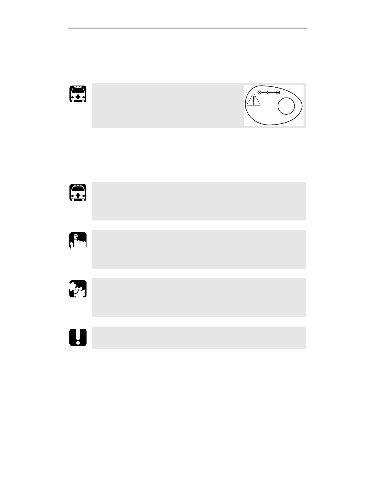
WARNING
Use the AC adapter provided with this product
indoors only.
WARNING
Indicates a potentially hazardous situation which, if not avoided,
could result in death or serious injury. Do not proceed unless you
understand and meet the required conditions.
CAUTION
Indicates a potentially hazardous situation which, if not avoided,
may result in minor or moderate injury. Do not proceed unless you
understand and meet the required conditions.
CAUTION
Indicates a potentially hazardous situation which, if not avoided,
may result in component damage. Do not proceed unless you
understand and meet the required conditions.
IMPORTANT
Refers to information about this product you should not overlook.
Q
S
T
5
1
9
A
150 mA
6 -16 V DC
Page 9
PPM-350B 5
3 Getting Started with Your
PPM-350B PON Power
Meter
Turning the Unit On and Off
When you turn the PPM-350B PON Power Meter off, it saves the current mode
(Pass/Fail or Normal) and threshold set. On models supporting relative-power
measurement, unit and reference values are also kept in memory.
Note: Offset nulling values are always returned to factory settings.
To t u r n t h e un i t on :
Press . The unit displays EXFO for a few seconds and vertical bars move at the
top of the display, indicating the initialization is in progress. You may use your unit
immediately under normal conditions. The unit is in Pass/Fail or Normal mode,
depending on which mode was used last time.
To turn the unit off:
From Pass/Fail or Normal modes (not threshold selection mode or correction factor
mode), hold down a few seconds.
IMPORTANT
If you remove batteries (and the AC adapter is unplugged), the unit
will turn off without saving the above values.
If batteries are low (and the AC adapter is unplugged), the unit will
save the above values and turn off.
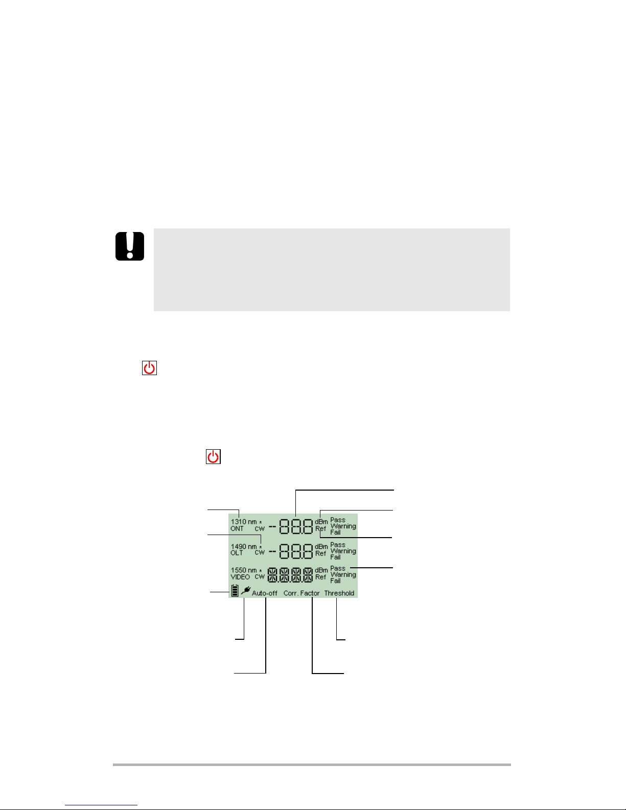
Batteries in use
(with level;
blinking when
weak)
Status
Signal (wavelength)
Power level
Reference values displayed
(models supporting this
feature)
Display
Auto-off activated
AC adapter plugged in
Units
Correction factors displayed
Threshold selection mode
activated
Correction
factor not
equal to 0 dB
Page 10

Getting Started with Your PPM-350B PON Power Meter 6
Activating Automatic Shutdown (Auto-Off)
When auto-off is activated, the unit will turn itself off
after 10 minutes of idle time.
Auto-off is activated by default when you turn unit on.
To deactivate/reactivate auto-off:
Press .
PRESS: Turns unit on
Controls auto-off
Exits special modes
HOLD: Turns unit off
PRESS: Switches between
measurement units and
deactivates Pass/Fail mode
HOLD: Displays correction factors
PRESS: Displays reference values for a few
seconds, then switches units to dB and
deactivates Pass/Fail mode.
HOLD: Sets input power as reference power
for all wavelengths
Accesses threshold selection
mode
Activates/deactivates Pass/Fail mode
(not possible during nulling, threshold
verification, LEDs/LCD verification)
Keypad (models that can measure relative power)
PRESS: Turns unit on
Controls auto-off
Exits special modes
HOLD: Turns unit off
PRESS: Switches between ONT and
OLT/video signals (on 1-port models)
HOLD: Displays correction factors
Accesses threshold selection
mode
PRESS: Activates/deactivates Pass/Fail mode
(not possible during nulling, threshold
verification, LEDs/LCD verification)
Keypad (other models)
Page 11
PPM-350B 7
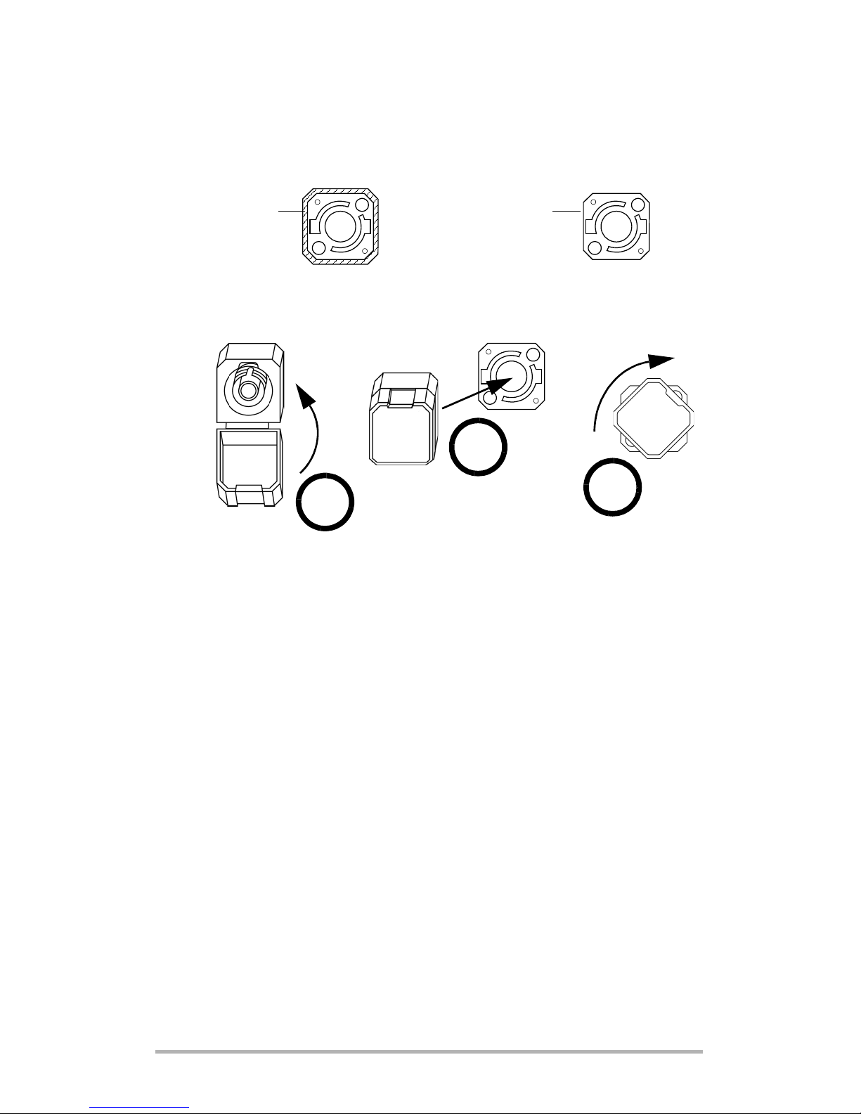
Installing the EXFO Universal Interface (EUI)
The EUI fixed baseplate is available for connectors with angled (APC) or non-angled
(UPC) polishing. A green border around the baseplate indicates that it is for
APC-type connectors, as shown below:
To install an EUI connector adapter onto the EUI baseplate:
1. Hold the EUI connector adapter so the dust cap opens downwards.
2. Close the dust cap in order to hold the connector adapter more firmly.
3. Insert the connector adapter into the baseplate.
4. While pushing firmly, turn the connector adapter clockwise on the baseplate to
lock it in place.
Bare metal
(or blue border)
indicates UPC option
Green border
indicates APC
option
2
4
3
Page 12

Getting Started with Your PPM-350B PON Power Meter 8
Cleaning and Connecting Optical Fibers
To connect the fiber-optic cable to the port:
1. Clean the fiber ends as follows:
1a. Gently wipe the fiber end with a lint-free swab dipped in isopropyl alcohol.
1b. Use compressed air to dry completely.
1c. Visually inspect the fiber end to ensure its cleanliness.
2. Carefully align the connector and port to prevent the fiber end from touching the
outside of the port or rubbing against other surfaces. If your connector features
a key, ensure that it is fully fitted into the port’s corresponding notch.
3. Push the connector in so that the fiber-optic cable is firmly in place, thus
ensuring adequate contact.
If your connector features a screwsleeve, tighten the connector enough to firmly
maintain the fiber in place. Do not overtighten, as this will damage the fiber and
the port.
Note: If your fiber-optic cable is not properly aligned and/or connected, you
will notice heavy loss and reflection.
IMPORTANT
To ensure maximum power and to avoid erroneous readings:
³ Always clean fiber ends as explained below before inserting
them into the port. EXFO is not responsible for damage or errors
caused by bad fiber cleaning or handling.
³ Ensure that your patchcord has appropriate connectors. Joining
mismatched connectors will damage the ferrules.
Page 13

PPM-350B 9
4 Configuring Thresholds
and Correction Factors
Your PPM-350B PON Power Meter offers 3 correction factors (one per wavelength)
and up to 10 threshold sets. On a properly calibrated PPM-350B PON Power Meter,
correction factors are set to 0 dB.
Correction factors are added to the measured values. For this reason, once the
correction factors are applied, your PPM-350B PON Power Meter may display “HI” or
“LO”, indicating the power levels are no longer within the unit’s power limits.
If you need to define correction factors of more than 1 dB or less than –1 dB to
compensate for inaccuracies, it may be a good idea to send your PPM-350B PON
Power Meter for recalibration (see Recalibrating the Unit on page 20). This will
ensure the results remain accurate.
The Handheld Data Transfer (provided on your CD) enables you to create new
threshold sets and correction factors or modify values retrieved from your PPM-350B
PON Power Meter. For more information, refer to Handheld Data Transfer online
help.
IMPORTANT
Both threshold sets and correction factors will be transferred to your
unit. Previous values will be lost.
Page 14

Testing with Your PPM-350B PON Power Meter 10
5 Testing with Your
PPM-350B PON Power
Meter
In this chapter, some instructions are identified as “Models measuring relative
power”. A quick way to confirm that your unit can measure relative power is to
verify if the keypad has a button.
Nulling Electrical Offsets
Temperature and humidity variations affect the performance of electronic circuits
and optical detectors. Nulling the electrical offsets eliminates these effects. Your unit
has been designed not to require offset nulling under normal operation, but you
should perform it whenever environmental conditions change significantly or when
measuring very low power values.
Note: Factory-defined values will be reinstated when you turn the unit off.
To perform an offset nulling:
³ [Models measuring relative power] Hold down
and a few seconds.
³ [Other models] Hold down and a
few seconds.
The unit displays NULL and vertical bars move at
the top of the display, indicating the nulling is in progress.
Note: Keypad is disabled during the operation.
The unit will then return to your previous mode (Pass/Fail or Normal).
IMPORTANT
If light reaches the detector when nulling offsets, LIGH appears on
the display and the nulling is not performed. You will need to press a
key to return to the previous display.
dBm/
dB
dBm/
dB
REF/
SEL
Threshold Select
Page 15

PPM-350B 11
Viewing Correction Factors
Applying a correction factor to measured power compensates for known power
gains or losses, or inaccuracies at specific wavelengths.
By default, correction factors
are set to 0 dB, because
properly calibrated units do not
require any correction factor.
Correction factors are added to
the values that are read. For this
reason, once the correction
factors are applied, your
PPM-350B PON Power Meter may display “HI” or “LO”, indicating the power levels
are no longer within the unit’s power limits.
Note: The unit takes correction factors into account in both Pass/Fail and
Normal modes.
To modify correction factors, you must use the Handheld Data Transfer (refer to the
Handheld Data Transfer online help).
To view correction factors on your unit:
1. [Models measuring relative power] Hold down
for a few seconds.
[Other models] Hold down for a few
seconds.
The unit displays correction factors (one per
wavelength).
2. Press to return to your previous mode (Pass/Fail or Normal).
Selecting a Threshold Set
You can select which threshold set will be used to determine the Pass/Warning/Fail
status. Your unit contains up to 10 threshold sets, but only one set can be selected at
a time.
A threshold set comprises three wavelengths (1310, 1490 and 1550 nm), each of
them having specific threshold values for pass, warning and fail.
Note: Thresholds are used in Pass/Fail mode only.
You can view thresholds directly on your unit. To modify threshold values, you must
use the Handheld Data Transfer (refer to the Handheld Data Transfer online help).
Correction
factor not
equal to 0 dB
Signal (wavelength)
dBm/
dB
Select
Page 16

Testing with Your PPM-350B PON Power Meter 12
To select a threshold set:
1. Press . The unit enters the threshold
selection mode and displays the current
threshold set. If the threshold name has more
than 4 characters, it will scroll automatically.
2. Press to switch between available
threshold sets.
3. If desired, display the Pass/Warning/Fail values of the threshold set as follows:
3a. Hold down for a few seconds. The
unit displays threshold values of the first
wavelength that has not been deactivated.
3b. Press to switch to next wavelength.
Note: If a wavelength has been deactivated via
the Handheld Data Transfer (refer to the
Handheld Data Transfer online help), the
unit displays no threshold values.
3c. Press to return to threshold selection mode.
4. [Models measuring relative power] Press to make the displayed threshold
set the current one.
[Other models] Press to make the displayed threshold set the current
one.
The unit returns to Pass/Fail mode.
5. Press to exit without selecting a new threshold set. The unit returns to your
previous mode (Pass/Fail or Normal).
Threshold set number
Current threshold set indicators
Threshold set name
Threshold
Threshold
Signal (wavelength)
Threshold
Threshold
REF/
SEL
Select
Page 17

PPM-350B 13
Testing in Pass/Fail Mode or in Normal Mode
³ Pass/Fail mode: status is indicated directly (screen and LEDs). Status is
determined according to the current threshold set (see Selecting a Threshold
Set on page 11).
³ Normal mode: only the power levels are shown and LEDs are off.
Note: If the result is greater than the Pass threshold, the word Fail and the LED
will flash. If the result is lower than the Fail threshold, the unit will only
display Fail and the LED will not flash.
Note: On 1-port units, you will only see values at 1490 nm and 1550 nm.
At startup, the unit is in the same mode that was used during last test session.
You may activate the Pass/Fail mode at any time (except during nulling, threshold
verification, and LEDs and LCD verification).
Pass/Fail Normal
Signal (wavelength)
Power levels (dBm; dB only
possible with models
measuring relative power)
Status
LEDs are on:
Green (Pass),
Yellow (Warning), Red (Fail)
Correction factor not
equal to 0 dB
When power is outside unit’s power limits
(see Technical Specifications on page 31)
Power levels (dBm only)
Page 18

Testing with Your PPM-350B PON Power Meter 14
To test in Pass/Fail or Normal mode with a 1-port model:
1. Clean your fibers properly as explained in Cleaning and Connecting Optical
Fibers on page 8.
2. Connect as shown:
3. Tu r n unit on.
4. Press to select OLT/video signal.
5. If you want to test in Pass/Fail mode:
³ Ensure that LEDs are on. If not, press .
³ Ensure that the desired threshold set is selected (see Selecting a Threshold
Set on page 11).
Results are now available.
Test at the premises
Te s t j u m pe r
Drop cable
Bulkhead connector
OLT/Video signal
Test at the drop terminal
Tes t j u m p e r
OLT/Video signal
Splitter’s output pigtail
Bulkhead connector
Tes t j u m p e r
Test at the f iber d istribution hub (FDH)
Select
P/F
mode
Page 19

PPM-350B 15
To test in Pass/Fail or Normal mode with a 2-port model:
1. Clean your fibers properly as explained in Cleaning and Connecting Optical
Fibers on page 8.
2. Connect as shown:
3. Tu r n unit on.
4. If you want to test in Pass/Fail mode:
³ Ensure that LEDs are on. If not, press .
³ Ensure that the desired threshold set is selected (see Selecting a Threshold
Set on page 11).
Results are now available.
Test at the premises
Tes t j u m p e r
ONT port
Tes t j u m p e r
OLT/video port
Drop cable
Bulkhead connector
Test at the drop terminal
Tes t j u m p e r
ONT port
Tes t j u m p e r
OLT/video port
Bulkhead connector
Drop cable
ONT port
Tes t j u m p e r
OLT/video port
Splitter’s output pigtail
Bulkhead connector
Te s t j u m pe r
Test at the fiber distribution hub (FDH)
P/F
mode
Page 20

Testing with Your PPM-350B PON Power Meter 16
Measuring Loss Between Two Points
You can measure loss between two locations using a single PPM-350B PON Power
Meter.
Note: This type of test is only possible with models measuring relative power.
To measure loss between two points:
1. Clean your fibers properly as explained in Cleaning and Connecting Optical
Fibers on page 8.
2. At location A, connect as shown:
Test at the premises
Tes t j u m p e r
ONT port
Tes t j u m p e r
OLT/video port
Drop cable
Bulkhead connector
Test at the drop terminal
Tes t j u m p e r
ONT port
Tes t j u m p e r
OLT/video port
Bulkhead connector
Drop cable
ONT port
Tes t j u m p e r
OLT/video port
Splitter’s output pigtail
Bulkhead connector
Te s t j u m pe r
Test at the fiber distribution hub (FDH)
Page 21

PPM-350B 17
3. Tu r n unit on.
4. Hold down for a few seconds to take reference
(all 3 wavelengths simultaneously).
5. If desired, press once to view reference values.
6. Press to select dB. You should see 0 dB at
each wavelength.
7. When you are done, disconnect and turn unit off.
8. Repeat steps 1 to 3 at location B, using the same PPM-350B PON Power Meter.
9. Press to select dB.
Results are displayed.
REF/
SEL
REF/
SEL
dBm/
dB
Signals (wavelengths)
Relative power at each wavelength
(loss between location A and B)
dBm/
dB
Page 22

Maintenance 18
6 Maintenance
To help ensure long, trouble-free operation:
³ Always clean fiber-optic connectors before using them.
³ Keep the unit free of dust.
³ Clean the unit casing and front panel with a cloth slightly dampened with water.
³ Store unit at room temperature in a clean and dry area. Keep the unit out of
direct sunlight.
³ Avoid high humidity or significant temperature fluctuations.
³ Avoid unnecessary shocks and vibrations.
³ If any liquids are spilled on or into the unit, turn off the power immediately and
let the unit dry completely.
Cleaning EUI Connectors
Regular cleaning of EUI connectors will help maintain optimum performance. There
is no need to disassemble the unit.
To clean EUI connectors:
1. Remove the EUI from the instrument to expose the connector baseplate and
ferrule.
2. Moisten a 2.5 mm cleaning tip provided by EXFO with one drop of isopropyl
alcohol (alcohol may leave traces if used abundantly).
3. Slowly insert the cleaning tip into the EUI adapter until it comes out on the other
side (a slow clockwise rotating movement may help).
WARNING
Use of controls, adjustments and procedures for operation and
maintenance other than those specified herein may result in
hazardous radiation exposure.
IMPORTANT
If any damage occurs to internal connectors, the module casing will
have to be opened and a new calibration will be required.
Push
Turn
Pull
Page 23

PPM-350B 19
4. Gently turn the cleaning tip one full turn, then continue to turn as you withdraw
it.
5. Repeat steps 3 to 4 with a dry cleaning tip.
Note: Make sure you don’t touch the soft end of the cleaning tip.
6. Clean the ferrule in the connector port as follows:
6a. Deposit one drop of isopropyl alcohol on a lint-free wiping cloth.
6b. Gently wipe the connector and ferrule.
6c. With a dry lint-free wiping cloth, gently wipe the same surfaces to ensure
that the connector and ferrule are perfectly dry.
6d. Verify connector surface with a portable fiber-optic microscope
(e.g., EXFO’s FOMS) or fiber inspection probe (e.g., EXFO’s FIP).
7. Put the EUI back onto the instrument (push and turn clockwise).
8. Throw out cleaning tips and wiping cloths after one use.
IMPORTANT
Since isopropyl alcohol is not absolutely pure, it may leave residues
if used abundantly or left to evaporate (about 10 seconds).
Avoid contact between the tip of the bottle and the wiping cloth,
dry the surface quickly, and use a bottle that distributes only a drop
of alcohol at a time.
WARNING
Verifying the surface of the connector WHILE THE UNIT IS ACTIVE
WILL result in permanent eye damage.
3
4
5
Page 24

Maintenance 20
Replacing Disposable Alkaline Batteries
Your unit requires three AA alkaline batteries.
Note: The provided AC adapter is not a charger.
To replace disposable alkaline batteries:
1. Turn off the unit (if the AC adapter is plugged in, you
may replace batteries while unit is on).
2. Open the battery compartment door located at the
back of the unit.
3. Replace batteries, respecting the polarity as shown.
4. Close the battery compartment door.
Recalibrating the Unit
Manufacturing and service center calibrations are based on the ISO/IEC 17025
Standard, which states that calibration documents must not contain a
recommended calibration interval, unless this has been previously agreed upon
with the customer.
Validity of specifications depends on operating conditions. For example, the
calibration validity period can be longer or shorter depending on the intensity of use,
environmental conditions and unit maintenance. You should determine the
adequate calibration interval for your unit according to your accuracy requirements.
Under normal use, EXFO recommends calibrating your unit every year.
Note: The FlexCare warranty program includes Calibration/Verification
packages (see Service and Repairs on page 29).
To view the last calibration date:
1. Hold down and press at the same
time. The unit displays the main embedded
software version.
2. Press to display the calibration date of the
unit.
3. Press to return to your previous mode (Pass/Fail
or Normal).
WARNING
Do not throw batteries into fire or water and do not short-circuit
the batteries’ electrical contacts.
+
+
+
YearMonth/Day
Threshold
Threshold
Page 25

PPM-350B 21
Verifying Thresholds
You can verify the threshold values to ensure that your unit will function normally
with any of the available threshold sets.
If a problem is detected, error code 12 will be displayed. If you turn the unit off
without correcting the problem, the error code will be displayed once the unit is
turned on again. For more information, see Error Codes and Descriptions on
page 24.
To verify thresholds:
Hold down and a few seconds. The
unit displays CHKS and vertical bars move at the top of
the display, indicating the verification is in progress.
Note: Keypad is disabled during this operation.
The unit will then return to your previous mode
(Pass/Fail or Normal).
Verifying the LEDs and LCD
You can verify that the LEDs function normally and that the screen can display all the
elements properly. The unit must be in Pass/Fail or Normal mode to perform the
verification.
To verify the LEDs and LCD:
1. Hold down and a few seconds. The unit
displays TEST and vertical bars move at the top of
the display, indicating the verification is in progress.
The three LEDs will light up briefly in the following
order: green, yellow, red. Once LEDs are turned off,
all the screen segments will be displayed at the
same time, allowing you to verify them.
Note: Keypad is disabled during the operation.
2. Press any key to return to your previous mode (Pass/Fail or Normal).
P/F
mode
Threshold
P/F
mode
Page 26

Maintenance 22
Recycling and Disposal (Applies to European
Union Only)
³ Unless otherwise noted in a separate agreement between EXFO and a
customer, distributor or commercial partner, EXFO will cover costs related to
the collection, treatment, recovery and disposal of end-of-lifecycle waste
generated by electronic equipment introduced after August 13, 2005 to an
European Union member state with legislation regarding Directive 2002/96/EC.
³ Except for reasons of safety or environmental benefit, equipment manufactured
by EXFO, under its brand name, is generally designed to facilitate dismantling
and reclamation.
For complete recycling/disposal procedures and contact information, visit the EXFO
Web s ite at www.exfo.com/recycle.
Recycle or dispose of your product (including electric and electronic
accessories) properly, in accordance with local regulations. Do not
dispose of it in ordinary garbage receptacles.
This equipment was sold after August 13, 2005 (as identified by the
black rectangle).
Page 27

PPM-350B 23
7 Troubleshooting
Solving Common Problems
Problem Possible Cause Solution
One of the LEDs remains
off.
OR
One of the LEDs remains
green or red even if the
status is Warning.
LED is burnt.
Verify LEDs (see Verifying
the LEDs and LCD on
page 21).
Contact EXFO.
Pressing the button
does not activate Pass/Fail
mode.
³ Unit is currently
nulling offsets,
verifying thresholds or
verifying LEDs and
LCD.
³ Let the unit complete
the operation.
If the unit was
verifying LEDs and
LCD, press any key to
return to your previous
mode (Pass/Fail or
Normal).
³ The current threshold
set contains an
unusable (corrupted)
value.
³ See Error Codes and
Descriptions on
page 24.
³ No threshold sets have
been defined.
³ See Error Codes and
Descriptions on
page 24.
The threshold set name is
not displayed correctly.
Name contains characters
that your unit cannot
display. Unsupported
characters are replaced
with dashes, spaces or
“+”.
Rename the threshold set
using only supported
characters:
³ 0 through 9
³ A through Z (both
lowercase and
uppercase)
³ - (dash) + / . < = > ?
[ \ ] _ (underscore)
and space
For more information on
renaming threshold sets,
see Configuring
Thresholds and Correction
Facto rs on page 9.
P/F
mode
Page 28

Troubleshooting 24
Error Codes and Descriptions
³ ER: error code displayed until you press a key.
³ WR: warning code displayed for 3 seconds, then unit returns to normal.
[1-port models] In
Pass/Fail mode, only the
battery charge and the
auto-off indicators are
displayed.
You selected O N T
(1310 nm), but this signal
has been deactivated in
the current threshold set
(see Selecting a Threshold
Set on page 11).
[1-port models]
Impossible to see the
current wavelength(s) and
the corresponding LED(s)
is (are) off.
The signal is deactivated
(see Selecting a Threshold
Set on page 11).
Reactivate the signal (see
Configuring Thresholds
and Correction Factors on
page 9).
[2-port models] In
Pass/Fail mode,
Impossible to see all
wavelengths and some of
the LEDs are off.
At least one signal is
deactivated (see Selecting
a Threshold Set on
page 11).
Error
Code
Description Solution
LIGH Light detected while nulling offsets.
Nulling is not performed.
Correctly place protective cap on
ports, then retry. If the problem
persists, contact EXFO.
ER 12/16 Threshold values are not usable
(corruption problem).
Would occur:
³ during unit initialization
³ after threshold verification (see
Verifying Thresholds on page 21)
³ after threshold set selection
Download new threshold sets to
your unit. For more information,
see Configuring Thresholds and
Correction Factors on page 9.
ER 13 EEPROM corrupted (would occur
during unit initialization).
Unit must be recalibrated.
Contact EXFO.
WR 23 No threshold sets have been defined.
Pass/Fail mode cannot be activated.
Download new threshold sets to
your unit. For more information,
see Configuring Thresholds and
Correction Factors on page 9.
Problem Possible Cause Solution
Page 29

PPM-350B 25
Contacting the Technical Support Group
To obtain after-sales service or technical support for this product, contact EXFO at
one of the following numbers. The Technical Support Group is available to take your
calls from Monday to Friday, 7:30 a.m. to 8:00 p.m. (Eastern Time in North America).
To accelerate the process, please have information such as the name and the serial
number (see the product identification label—an example is shown below), as well
as a description of your problem, close at hand.
You may also be requested to provide the embedded software’s version numbers.
To display the embedded software version:
1. Hold down and press at the same
time. The unit displays the main software version.
2. Press to return to your previous mode
(Pass/Fail or Normal).
Technical Support Group
400 Godin Avenue
Quebec (Quebec) G1M 2K2
CANADA
1 866 683-0155 (USA and Canada)
Tel.: 1 418 683-5498
Fax: 1 418 683-9224
support@exfo.com
Ver.
Mfg.
date
P/N
S/N
Made in Canada QST442B
465 Godin Avenue
Vanier (Quebec) G1M 3G7 CANADA
**************** A
January 2003
542392-3D
PPM-35XB-XX
Model Connector code
Threshold
Page 30

Troubleshooting 26
Finding Information on the EXFO Web Site
The EXFO Web site provides answers to frequently asked questions (FAQs)
regarding the use of your PPM-350B PON Power Meter.
To access FAQs:
1. Ty pe http://www.exfo.com in your Internet browser.
2. Click on the Support tab.
3. Click on FAQs and follow the on-screen instructions. You will be given a list of
questions pertaining to your subject.
The EXFO Web site also provides the product’s most recent technical specifications.
Transportation
Maintain a temperature range within specifications when transporting the unit.
Transportation damage can occur from improper handling. The following steps are
recommended to minimize the possibility of damage:
³ Pack the unit in its original packing material when shipping.
³ Avoid high humidity or large temperature fluctuations.
³ Keep the unit out of direct sunlight.
³ Avoid unnecessary shock and vibration.
Page 31

PPM-350B 27
8 Warranty
General Information
EXFO Electro-Optical Engineering Inc. (EXFO) warrants this equipment against
defects in material and workmanship for a period of one year from the date of
original shipment. EXFO also warrants that this equipment will meet applicable
specifications under normal use.
During the warranty period, EXFO will, at its discretion, repair, replace, or issue
credit for any defective product, as well as verify and adjust the product free of
charge should the equipment need to be repaired or if the original calibration is
erroneous. If the equipment is sent back for verification of calibration during the
warranty period and found to meet all published specifications, EXFO will charge
standard calibration fees.
THIS WARRANTY IS IN LIEU OF ALL OTHER WARRANTIES EXPRESSED, IMPLIED,
OR STATUTORY, INCLUDING, BUT NOT LIMITED TO, THE IMPLIED WARRANTIES OF
MERCHANTABILITY AND FITNESS FOR A PARTICULAR PURPOSE. IN NO EVENT
SHALL EXFO BE LIABLE FOR SPECIAL, INCIDENTAL, OR CONSEQUENTIAL
DAMAGES.
Liability
EXFO shall not be liable for damages resulting from the use of the product, nor shall
be responsible for any failure in the performance of other items to which the
product is connected or the operation of any system of which the product may be a
part.
EXFO shall not be liable for damages resulting from improper usage or unauthorized
modification of the product, its accompanying accessories and software.
IMPORTANT
The warranty can become null and void if:
³ unit has been tampered with, repaired, or worked upon by
unauthorized individuals or non-EXFO personnel.
³ warranty sticker has been removed.
³ case screws, other than those specified in this guide, have been
removed.
³ case has been opened, other than as explained in this guide.
³ unit serial number has been altered, erased, or removed.
³ unit has been misused, neglected, or damaged by accident.
Page 32

Warranty 28
Exclusions
EXFO reserves the right to make changes in the design or construction of any of its
products at any time without incurring obligation to make any changes whatsoever
on units purchased. Accessories, including but not limited to fuses, pilot lamps,
batteries and universal interfaces (EUI) used with EXFO products are not covered by
this warranty.
This warranty excludes failure resulting from: improper use or installation, normal
wear and tear, accident, abuse, neglect, fire, water, lightning or other acts of nature,
causes external to the product or other factors beyond EXFO’s control.
Certification
EXFO certifies that this equipment met its published specifications at the time of
shipment from the factory.
IMPORTANT
EXFO will charge a fee for replacing optical connectors that were
damaged due to misuse or bad cleaning.
Page 33

PPM-350B 29
Service and Repairs
EXFO commits to providing product service and repair for five years following the
date of purchase.
To send any equipment for service or repair:
1. Call one of EXFO’s authorized service centers (see EXFO Service Centers
World wi de on page 30). Support personnel will determine if the equipment
requires service, repair, or calibration.
2. If equipment must be returned to EXFO or an authorized service center, support
personnel will issue a Return Merchandise Authorization (RMA) number and
provide an address for return.
3. If possible, back up your data before sending the unit for repair.
4. Pack the equipment in its original shipping material. Be sure to include a
statement or report fully detailing the defect and the conditions under which it
was observed.
5. Return the equipment, prepaid, to the address given to you by support
personnel. Be sure to write the RMA number on the shipping slip. EXFO will
refuse and return any package that does not bear an RMA number.
Note: A test setup fee will apply to any returned unit that, after test, is found to
meet the applicable specifications.
After repair, the equipment will be returned with a repair report. If the equipment is
not under warranty, you will be invoiced for the cost appearing on this report. EXFO
will pay return-to-customer shipping costs for equipment under warranty. Shipping
insurance is at your expense.
Routine recalibration is not included in any of the warranty plans. Since
calibrations/verifications are not covered by the basic or extended warranties, you
may elect to purchase FlexCare Calibration/Verification Packages for a definite
period of time. Contact an authorized service center (see EXFO Service Centers
World wi de on page 30).
Page 34

Warranty 30
EXFO Service Centers Worldwide
If your product requires servicing, contact your nearest authorized service center.
EXFO Headquarters Service Center
400 Godin Avenue
Quebec (Quebec) G1M 2K2
CANADA
1 866 683-0155 (USA and Canada)
Tel.: 1 418 683-5498
Fax: 1 418 683-9224
quebec.service@exfo.com
EXFO Europe Service Center
Le Dynasteur
10/12, rue Andras Beck
92366 Meudon la Forêt Cedex
FRANCE
Tel.: +33.1.40.83.85.85
Fax: +33.1.40.83.04.42
europe.service@exfo.com
EXFO China Service Center/
Beijing OSIC
Beijing New Century Hotel
Office Tower, Room 1754-1755
No. 6 Southern Capital Gym Road
Beijing 100044
P. R . C H I N A
Tel.: +86 (10) 6849 2738
Fax: +86 (10) 6849 2662
beijing.service@exfo.com
Page 35

PPM-350B 31
A Technical Specifications
IMPORTANT
The following technical specifications can change without notice.
The information presented in this section is provided as a reference
only. To obtain this product’s most recent technical specifications,
visit the EXFO Web site at www.exfo.com.
PPM-35XB-XX
Model
PPM-351B = PON power meter, one port BPON
PPM-352B = PON power meter, two ports BPON
PPM-352B-EG = PON power meter, two ports
BPON, E PON, GPON
PPM-352B-EG-ER = PON power meter, two ports, extended
range, BPON, E PON, GPON
Example: PPM-352B-EG-ER-EA-E UI-91
STANDARD ACCESSORIES
User guide, three AA batteries, wrist strap, PC threshold-transfer software,
RS-232 cable, alcohol cleaning pads.
GENERAL SPECIFICATIONS
Size (H x W x D) 185 mm x 100 mm x 55 mm (7 1/4in x 4 in x 2 1/8in)
Weight 0.4 kg (0.9 lb)
Temperature
operating −10 °C to 5 0 °C (14 °F to 122 °F)
storage −40 °C to 70 °C (−40 °F to 158 °F)
Relative humidity 0 % to 95 % non-condensing
Notes
1. Same connectors for b oth ports on two-ports version.
Connector
1
EI-EUI-28 = UPC/D IN 47256
EI-EUI-76 = UPC/ HMS-10/AG
EI-EUI-89 = UPC/FC narrow key
EI-EUI-90 = UPC/ST
EI-EUI-91 = UPC/SC
EI-EUI-95 = UPC/E-2000
EA-EUI-28 = AP C/DIN 47256
EA-EUI-89 = APC/ FC narrow key
EA-EUI-91 = AP C/SC
EA-EUI-95 = AP C/E-2000
PPM-351B PPM-352B PPM-352B-EG PPM-352B-EG-ER
BPON EPON/GPON
Power measurement range – pass zone 1490 nm 1 to −33 1 to −33 1 to −33 12 to −40
for continuous data stream (dBm) 1550 nm 15 to −36 15 to −36 15 to −36 252to −40
Burst mode measurement capability: Splitter to ONT Splitter to ONT Splitter to ONT CO to ONT
Burst mode measurement range2(dBm) 1310 nm 5.5 to −15 5.5 to −15 5.5 to −24 10 to –33 10 to −29
ORL3(dB) 1550 nm 55 55 55 55
Pass through insertion loss2(dB) 1.5 1.5 1.5 1.5
Spectral passband (nm) 1310 nm 1260 to 1360 1260 to 1360 1260 to 1360 1260 to 1360
1490 nm 1480 to 1500 1480 to 1500 1480 to 1500 1480 to 1500
1550 nm 1539 to 1565 1539 to 1565 1539 to 1565 1539 to 1565
Power uncertainty at calibrated 0.5 0.5 0.5 0.5
wavelengths
2, 4
(dB)
Refresh rate of display (Hz) 2.5 2.5 2.5 2.5
Calibrated wavelengths (nm) 1310, 1490, 1550 1310, 1490, 1550 1310, 1490, 1550 1310, 1490, 1550
Threshold sets 10 configurable threshold sets with threshold naming
Autonomy2(hours) > 30 > 30 > 30 > 30
Number of ports 1 2 2 2
Warranty and recommended 1 1 1 1
calibration interval (year)
Notes
1. At room temperature.
2. Typical.
3. For APC connectors. Typically
> 35 dB for UPC connectors.
4. Around –7 dBm, CW.
ORDERING INF ORMATION
Page 36

www.exfo.com · info@exfo.com
Printed in Canada (2006-03)
© 2006 EXFO Electro-Optical Engineering Inc. All rights reserved.
P/N: 1043827
CORPORATE
HEADQUARTERS
400 Godin Avenue Quebec (Quebec) G1M 2K2 CANADA
Tel.: 1 418 683-0211 · Fax: 1 418 683-2170
EXFO AMERICA 3701 Plano Parkway, Suite 160 Plano TX, 75075 USA
Tel.: 1 972 907-1505 ·
EXFO EUROPE Le Dynasteur
10/12, rue Andras Beck
92366 Meudon la Forêt Cedex FRANCE
Tel.: +33.1.40.83.85.85 · Fax: +33.1.40.83.04.42
EXFO ASIAPACIFIC
151 Chin Swee Road
#03-29, Manhattan House
SINGAPORE 169876
Tel.: +6563338241 · Fax: +6563338242
TOLL-FREE (USA and Canada) 1 800 663-3936
 Loading...