

EXFO Power Blazer 88000 Series, Power Blazer 88200NGE, Power Blazer 8880, Power Blazer 8870, Power Blazer 88400NGE User Manual
...Page 1
HIGH-SPEED MULTISERVICE TEST MODULE
Power Blazer
88000 Series
User Guide
Page 2

Copyright © 2014–2018 EXFO Inc. All rights reserved. No part of this
publication may be reproduced, stored in a retrieval system or transmitted
in any form, be it electronically, mechanically, or by any other means such
as photocopying, recording or otherwise, without the prior written
permission of EXFO Inc. (EXFO).
Information provided by EXFO is believed to be accurate and reliable.
However, no responsibility is assumed by EXFO for its use nor for any
infringements of patents or other rights of third parties that may result from
its use. No license is granted by implication or otherwise under any patent
rights of EXFO.
EXFO’s Commerce And Government Entities (CAGE) code under the North
Atlantic Treaty Organization (NATO) is 0L8C3.
The information contained in this publication is subject to change without
notice.
Trademarks
EXFO’s trademarks have been identified as such. However, the presence
or absence of such identification does not affect the legal status of any
trademark.
Units of Measurement
Units of measurement in this publication conform to SI standards and
practices.
Patents
Dual Test Set/Bi-Directional testing is protected by US patent 9,432,206 and
equivalents in other countries.
Feature(s) of this product is/are protected by one or more of: US design
patent D798,171 and equivalent(s) in other countries.
May 2, 2018
Document version: 4.0.0.1
ii 88000 Series
Page 3

Contents
Certification Information ........................................................................................................x
1 Introducing the High-Speed Multiservice Test Module .............................. 1
Features ..................................................................................................................................1
Technical Specifications ...........................................................................................................2
Conventions ............................................................................................................................3
2 Safety Information ....................................................................................... 5
Additional Laser Safety Information .......................................................................................7
Installation Instruction Warnings ............................................................................................8
3 Getting Started .......................................................................................... 11
Inserting and Removing Test Modules .................................................................................11
Inserting and Removing Transceiver Adaptors (TA) ..............................................................12
Turning On the Unit ..............................................................................................................14
Starting the Module Application ...........................................................................................15
4 Physical Interfaces and LEDs ..................................................................... 17
Port Availability on the 88000 Series ...................................................................................20
Transceivers ..........................................................................................................................24
RJ45 ......................................................................................................................................24
BNC ......................................................................................................................................25
SMB ......................................................................................................................................25
LEDs ......................................................................................................................................25
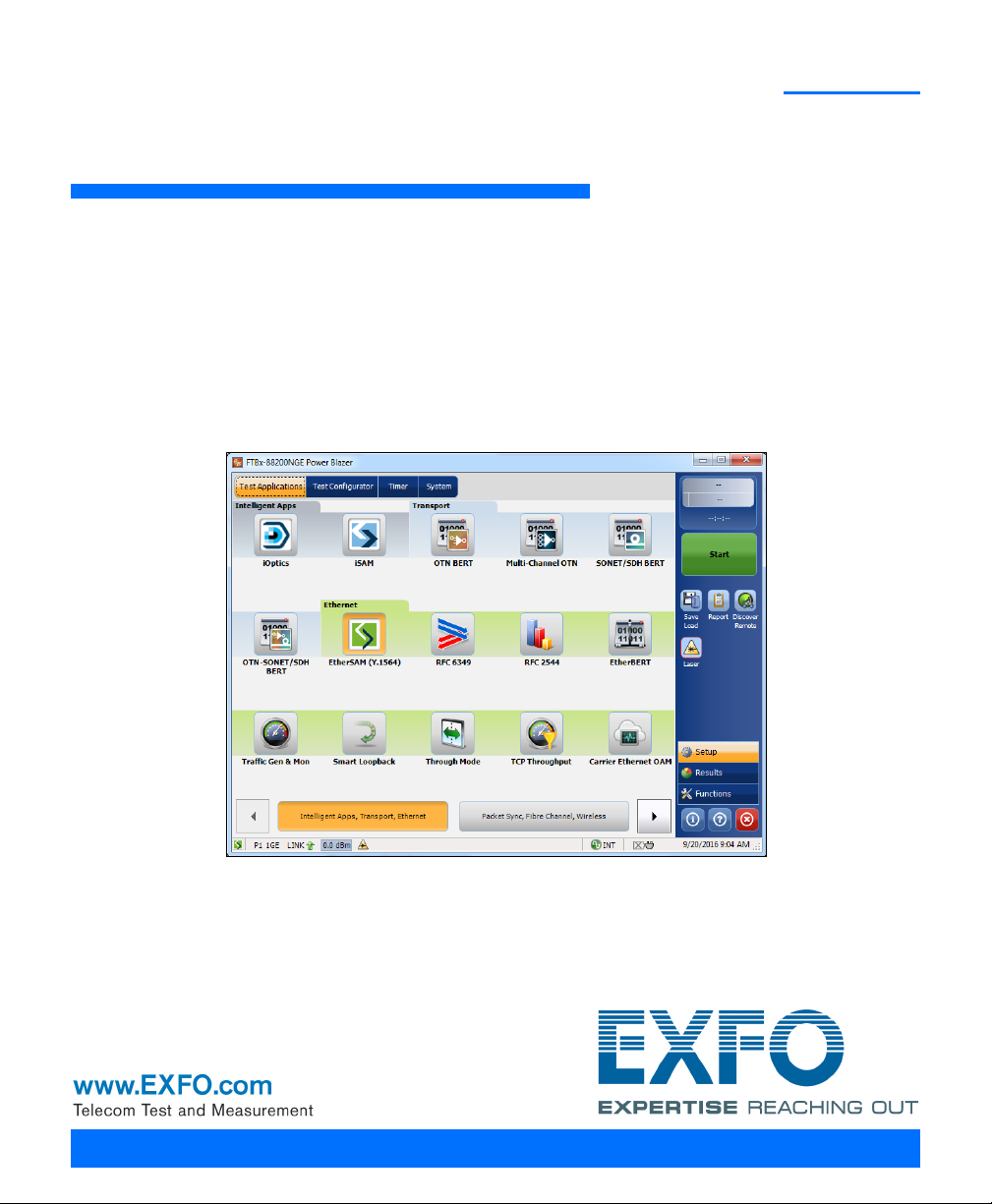
5 Graphical User Interface Overview ............................................................ 27
Main Application Window ...................................................................................................27
Main Window .......................................................................................................................27
Navigation Buttons ...............................................................................................................28
Status Bar ...........................................................................................................................28
Title Bar ...............................................................................................................................31
Global Indicator ....................................................................................................................31
Test Control .........................................................................................................................33
Test Menu ............................................................................................................................33
Application Buttons .............................................................................................................34
Zoomed-In/Zoomed-Out Views .............................................................................................37
Arrow Buttons .....................................................................................................................37
Keyboard Usage ...................................................................................................................38
Power Blazer iii
Page 4

6 Test Setup - Test Applications ....................................................................41
iOptics ..................................................................................................................................42
iSAM .....................................................................................................................................43
Multi-Channel OTN ...............................................................................................................44
OTN BERT ..............................................................................................................................45
OTN-SONET/SDH BERT ..........................................................................................................47
SONET/SDH BERT ..................................................................................................................50
DSn/PDH BERT ......................................................................................................................53
SONET/SDH - DSn/PDH BERT ................................................................................................55
NI/CSU Emulation ................................................................................................................58
EtherSAM (Y.1564) ................................................................................................................59
RFC 2544 ..............................................................................................................................61
RFC 6349 ..............................................................................................................................63
EtherBERT .............................................................................................................................64
Traffic Gen & Mon ................................................................................................................66
Smart Loopback ....................................................................................................................68
Through Mode ......................................................................................................................70
TCP Throughput ....................................................................................................................71
Carrier Ethernet OAM ..........................................................................................................72
Cable Test .............................................................................................................................74
1588 PTP ...............................................................................................................................75
SyncE ....................................................................................................................................76
Wander .................................................................................................................................77
FC BERT ................................................................................................................................78
CPRI/OBSAI BERT ..................................................................................................................79
7 Selecting and Starting a Test .....................................................................81
Intelligent Apps ....................................................................................................................81
Transport Test Applications ...................................................................................................85
Ethernet Test Applications ....................................................................................................87
Sync Test Applications ...........................................................................................................89
Fibre Channel Test Application ..............................................................................................91
Wireless Test Application ......................................................................................................93
iv 88000 Series
Page 5

8 Test Setup - Test Configurator, Timer, and System .................................. 95
Test Configurator Overview .................................................................................................100
Modify Structure Button ....................................................................................................108
Signal Auto-Detect ............................................................................................................131
1588 PTP ............................................................................................................................132
BERT and Unframed BERT ...................................................................................................139
Cable Test ..........................................................................................................................145
CFP4/CFP8/QSFP/SFP/SFP+/SFP28 .......................................................................................147
Clock ..................................................................................................................................148
EtherBERT, FC BERT, BERT (CPRI/OBSAI), and Unframed BERT .............................................155
EtherSAM - Burst ...............................................................................................................163
EtherSAM - Global .............................................................................................................165
EtherSAM - Ramp ..............................................................................................................169
External Reference .............................................................................................................171
Fibre Channel .....................................................................................................................172
Frequency ...........................................................................................................................175
FTFL/PT and PT ...................................................................................................................177
GFP-F/GFP-T ........................................................................................................................181
Interface (Ethernet, Packet Sync, Fibre Channel, and Wireless) ..........................................182
Labels ................................................................................................................................196
Link OAM ...........................................................................................................................198
Local Details (iSAM) ...........................................................................................................200
MAC/IP/UDP .......................................................................................................................204
Network .............................................................................................................................220
Network Details (iSAM) ......................................................................................................226
ODU Channels - Global ......................................................................................................237
Optical Device Under Test (iOptics) ....................................................................................245
Remote Details (iSAM) .......................................................................................................248
RFC 2544 - Global ..............................................................................................................252
RFC 2544 - Subtests ...........................................................................................................255
RFC 6349 ...........................................................................................................................264
S-OAM and MPLS-TP OAM .................................................................................................267
Services - Global ................................................................................................................277
Services - Profile .................................................................................................................280
Signal (Transport) ..............................................................................................................287
Signal - Signal Configuration (DSn/PDH) ............................................................................294
Signal - Signal Configuration (OTN) ...................................................................................302
Signal - Signal Configuration (SONET/SDH) ........................................................................307
Smart Loopback .................................................................................................................311
Streams - Global ................................................................................................................313
Streams - Profile ................................................................................................................315
SyncE .................................................................................................................................323
Power Blazer v
Page 6

System ...............................................................................................................................325
TA-SFP28 ............................................................................................................................326
TCP Throughput .................................................................................................................327
Test Sequence (iOptics) ......................................................................................................329
Timer .................................................................................................................................330
Traces (OTN) ......................................................................................................................332
Traces (SONET/SDH) ...........................................................................................................336
Wander ..............................................................................................................................338
9 Test Results ................................................................................................341
Alarms/Errors Overview .......................................................................................................344
Analysis - MTIE/TDEV .........................................................................................................417
Analysis - Time Error / Time Interval Error ..........................................................................419
FTFL/PT and PT ...................................................................................................................421
GFP-F/GFP-T ........................................................................................................................423
Graph (RFC 2544) ..............................................................................................................426
Labels ................................................................................................................................427
Link OAM ...........................................................................................................................428
Logger ...............................................................................................................................432
Messages ...........................................................................................................................434
MPLS .................................................................................................................................436
OTL-SDT ..............................................................................................................................437
Performance Monitoring ....................................................................................................439
PTP Stats ............................................................................................................................446
Quality Level (1588 PTP) ....................................................................................................448
Quality Level (SyncE) ..........................................................................................................450
S-OAM and MPLS-TP OAM .................................................................................................452
SDT (Multi-Channel OTN) ...................................................................................................457
Service Configuration - Burst .............................................................................................459
Service Configuration - Ramp ............................................................................................460
Service Performance ..........................................................................................................462
Streams - Frame Loss / Out-of-Sequence ............................................................................464
Streams - Jitter ...................................................................................................................464
Streams - Latency ..............................................................................................................465
Streams - Throughput / Customer Frame Throughput ........................................................466
Summary ...........................................................................................................................467
Summary (1588 PTP) .........................................................................................................474
Summary (Cable Test) ........................................................................................................479
Summary (EtherSAM) ........................................................................................................485
Summary (FC BERT) ............................................................................................................488
Summary (iOptics) .............................................................................................................491
Summary (iSAM) ................................................................................................................493
vi 88000 Series
Page 7

Summary (Link OAM) .........................................................................................................497
Summary (Multi-Channel OTN) ..........................................................................................499
Summary (NI/CSU Emulation) ............................................................................................501
Summary (RFC 2544) .........................................................................................................502
Summary (RFC 6349) .........................................................................................................505
Summary (S-OAM and MPLS-TP OAM) ...............................................................................508
Summary (SyncE) ...............................................................................................................513
Summary (TCP Throughput) ...............................................................................................516
Summary (Traffic Gen & Mon) ...........................................................................................519
Summary (Wander) ............................................................................................................521
Traces - OTN .......................................................................................................................525
Traces - SONET/SDH ...........................................................................................................527
Traffic - Ethernet ................................................................................................................528
Traffic - Flow Control .........................................................................................................531
Traffic - Graph ....................................................................................................................533
Traffic - OAM, S-OAM, and MPLS-TP OAM .........................................................................534
Window Sweep ..................................................................................................................536
WIS ....................................................................................................................................537
10 Test Functions ........................................................................................... 539
40/100G/400G Advanced - CFP4/CFP8/QSFP Control ..........................................................542
40/100G/400G Advanced - Lanes Mapping & Skew ...........................................................545
APS ....................................................................................................................................550
Client Offset ......................................................................................................................553
FDL - Bit-Oriented Message ................................................................................................556
FDL - Performance Report Message ...................................................................................560
FEAC ..................................................................................................................................563
Filters .................................................................................................................................567
Packet Capture ...................................................................................................................571
GCC BERT ...........................................................................................................................577
GMP ..................................................................................................................................579
OH - GFP-F/GFP-T ................................................................................................................580
OH - OTN ...........................................................................................................................585
OH - SONET/SDH ................................................................................................................591
Ping & Trace Route .............................................................................................................605
Pointer Adjustment ............................................................................................................610
RTD ....................................................................................................................................620
RTD/RTT (CPRI/OBSAI Framed L2) .......................................................................................623
S-OAM Link Trace ...............................................................................................................626
Signaling Bits .....................................................................................................................628
Spare Bits ...........................................................................................................................630
Traffic Scan ........................................................................................................................632
Power Blazer vii
Page 8

11 Test Control ...............................................................................................635
Discover Remote Button ....................................................................................................636
Inject Button .......................................................................................................................639
Laser Button .......................................................................................................................639
Lpbk Tool Button (Loopback Tool) ......................................................................................640
Report Button ....................................................................................................................647
Reset Button .......................................................................................................................652
Save/Load Button ...............................................................................................................653
Start/Stop|TX Button ..........................................................................................................657
12 Power Failure Recovery ............................................................................659
Enabling Power Failure Recovery .........................................................................................660
When Using the Test Timer .................................................................................................661
13 Maintenance ..............................................................................................663
Cleaning LC/SC/MPO-24 Connectors ...................................................................................664
Battery Safety Information .................................................................................................664
Recalibrating the Unit .........................................................................................................665
Recycling and Disposal .......................................................................................................666
14 Troubleshooting ........................................................................................667
Solving Common Problems .................................................................................................667
Contacting the Technical Support Group ............................................................................668
Transportation ....................................................................................................................668
15 Warranty ....................................................................................................669
General Information ...........................................................................................................669
Liability ...............................................................................................................................670
Exclusions ...........................................................................................................................671
Certification ........................................................................................................................671
Service and Repairs .............................................................................................................672
EXFO Service Centers Worldwide ........................................................................................673
A Specifications ............................................................................................675
viii 88000 Series
Page 9

B Glossary .................................................................................................... 677
Acronym List .......................................................................................................................677
10G Ethernet Client ............................................................................................................694
1588 PTP .............................................................................................................................697
CPRI ...................................................................................................................................703
Ethernet Cables .................................................................................................................708
G.709 Optical Transport Network (OTN) ............................................................................710
Generic Framing Procedure (GFP) ......................................................................................727
MPLS Labels ........................................................................................................................739
OBSAI ................................................................................................................................740
SONET/DSn/SDH/PDH ..........................................................................................................745
SyncE ..................................................................................................................................755
Unicast/Multicast Addresses for Ethernet OAM ..................................................................757
VLAN ID and Priority ...........................................................................................................758
C Remote ToolBox ....................................................................................... 759
Overview .............................................................................................................................759
Remote ToolBox Installation ................................................................................................761
Starting and Using the Remote ToolBox Application ..........................................................762
Applications for... ...............................................................................................................764
Index .............................................................................................................. 765
Power Blazer ix
Page 10

Certification Information
Certification Information
North America Regulatory Statement
This unit was certified by an agency approved in both Canada and the
United States of America. It has been evaluated according to applicable
North American approved standards for product safety for use in Canada
and the United States.
Electronic test and measurement equipment is exempt from FCC part 15,
subpart B compliance in the United States of America and from ICES-003
compliance in Canada. However, EXFO Inc. makes reasonable efforts to
ensure compliance to the applicable standards.
The limits set by these standards are designed to provide reasonable
protection against harmful interference when the equipment is operated in
a commercial environment. This equipment generates, uses, and can
radiate radio frequency energy and, if not installed and used in accordance
with the user guide, may cause harmful interference to radio
communications. Operation of this equipment in a residential area is likely
to cause harmful interference in which case the user will be required to
correct the interference at his own expense.
Modifications not expressly approved by the manufacturer could void the
user's authority to operate the equipment.
x 88000 Series
Page 11

Certification Information
European Community Declaration of Conformity
Warning: This is a class A product. In a domestic environment, this product
may cause radio interference in which case the user may be required to
take adequate measures.
The full text of the EU declaration of conformity is available at the following
Internet address: www.exfo.com/library.
Laser
Your instrument is a Class 1 laser product in compliance
with standards IEC 60825-1: 2007/2014 and 21 CFR
1040.10, except for deviations pursuant to Laser Notice
No. 42, dated December 18, 1989.
Power Blazer xi
Page 12

Page 13

1 Introducing the High-Speed
Multiservice Test Module
Turnkey field-test solution for deploying, validating, and troubleshooting
networks up to 400G.
Features
Features
88200NGE 88260 88400NGE 8870/8880
Intelligent Apps. iOptics X - X X
iSAM X - - X
Transport Multi-Channel OTN X - - -
OTN BERT X - - X
SONET/SDH BERT X - - X
OTN-SONET/SDH BERT X - - X
DSn/PDH BERT - - - X
SONET/SDH - DSn/PDH BERT - - - X
NI/CSU - - - X
Ethernet EtherSAM (Y.1564) X - - X
RFC 6349 X - - X
RFC 2544 X X - X
EtherBERT X X X X
Traffic Gen & Mon X X - X
Smart Loopback X X - X
Through Mode X - - X
TCP Throughput X - - X
Carrier Ethernet OAM X - - X
Cable Test - - - X
Model
Power Blazer 1
Page 14

Introducing the High-Speed Multiservice Test Module
Technical Specifications
Features
88200NGE 88260 88400NGE 8870/8880
Packet Sync 1588 PTP X - - X
SyncE X - - X
Wander - - - 8880
Fibre Channel FC BERT X - - X
Wireless CPRI/OBSAI BERT X - - X
Model
Technical Specifications
To obtain this product’s technical specifications, visit the EXFO Web site at
www.exfo.com.
2 88000 Series
Page 15

Introducing the High-Speed Multiservice Test Module
Conventions
Before using the product described in this guide, you should understand
the following conventions:
WARNING
Indicates a potentially hazardous situation which, if not avoided,
could result in death or serious injury. Do not proceed unless you
understand and meet the required conditions.
CAUTION
Indicates a potentially hazardous situation which, if not avoided,
may result in minor or moderate injury. Do not proceed unless you
understand and meet the required conditions.
CAUTION
Indicates a potentially hazardous situation which, if not avoided,
may result in component damage. Do not proceed unless you
understand and meet the required conditions.
Conventions
IMPORTANT
Refers to information about this product you should not overlook.
Power Blazer 3
Page 16

Page 17

2 Safety Information
WARNING
Do not install or terminate fibers while a light source is active.
Never look directly into a live fiber and ensure that your eyes are
protected at all times.
WARNING
The use of controls, adjustments and procedures, namely for
operation and maintenance, other than those specified herein may
result in hazardous radiation exposure or impair the protection
provided by this unit.
WARNING
If the equipment is used in a manner not specified by the
manufacturer, the protection provided by the equipment may be
impaired.
WARNING
Use only accessories designed for your unit and approved by EXFO.
For a complete list of accessories available for your unit, refer to its
technical specifications or contact EXFO.
Power Blazer 5
Page 18
Safety Information
When you see the following symbol on your unit , make sure
that you refer to the instructions provided in your user
documentation. Ensure that you understand and meet the required
conditions before using your product.
When you see the following symbol on your unit , it indicates
that the unit is equipped with a laser source, or that it can be used
with instruments equipped with a laser source. These instruments
include, but are not limited to, modules and external optical units.
Other safety instructions relevant for your product are located
throughout this documentation, depending on the action to
perform. Make sure to read them carefully when they apply to your
situation.
IMPORTANT
IMPORTANT
IMPORTANT
6 88000 Series
Page 19

Safety Information
Additional Laser Safety Information
Additional Laser Safety Information
This product employs Class 1 Laser transceivers.
WARNING
When the LASER LED is on or flashing, the module is transmitting an
optical signal on the transceiver ports.
Note: Refer to the platform’s user guide for additional test equipment safety
information and ratings.
Power Blazer 7
Page 20

Safety Information
Installation Instruction Warnings
Installation Instruction Warnings
When you use the unit outdoors, ensure that it is protected from
liquids, dust, direct sunlight, precipitation, and full wind pressure.
Except for the dual Bantam connector and the RJ-48C port, all
telecom (electrical) interfaces are SELV (Safety Extra Low Voltage)
circuitry intended for intra-building use only.
For the dual Bantam connector and the RJ-48C ports, use only No.
26 AWG or larger telecommunication line cord to reduce the risk of
fire.
CAUTION
CAUTION
CAUTION
CAUTION
No user serviceable parts are contained inside. Contact the
manufacturer regarding service of this equipment.
IMPORTANT
All wiring and installation must be in accordance with local building
and electrical codes acceptable to the authorities in the countries
where the equipment is installed and used.
WARNING
Use only accessories designed for your unit and approved by EXFO.
8 88000 Series
Page 21

Safety Information
Installation Instruction Warnings
CAUTION
Electrostatic Discharge (ESD) Sensitive Equipment:
Plug-in modules can be damaged by static electrical discharge. To
minimize the risk of damage, dissipate static electricity by touching
a grounded unpainted metal object
before removing, inserting, or handling the module.
before connecting or disconnecting cables to/from the module.
before inserting or removing a transceiver to/from the module.
Power Blazer 9
Page 22

Page 23

3 Getting Started
If the module has been purchased at the same time as the platform, the
module is pre-installed with the appropriate software version.
Number of Dedicated Modules per Platform
The following table lists the maximum number of dedicated modules that
can run simultaneously on each platform.
Platform 88200NGE 88260NGE 88400NGE 8870/8880
FTB-2 NA NA NA 2
FTB-2 Pro 2 2 NA 2
FTB-4 Pro 4 4 1
LTB -8 8 8 2 8
a. The platform needs to be connected to a power outlet since this module requires too
much power to run on battery power.
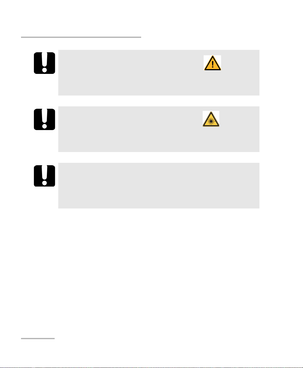
Inserting and Removing Test Modules
CAUTION
There is no need to turn off your unit before inserting or removing
FTBx- modules.
However, inserting/removing modules without following the
instructions provided in the platform user documentation could
result in the following consequences, depending on the operation
underway when the modules are inserted/removed:
a
4
unexpected behavior of the test applications,
instability of the system,
or cause irreparable damage to your modules.
Note: Refer to the platform user guide for more information on how to
insert/remove a module into/from the platform.
Power Blazer 11
Page 24

Getting Started
Screw
Handle
Inserting and Removing Transceiver Adaptors (TA)
Inserting and Removing Transceiver
Adaptors (TA)
CAUTION
There is no need to turn off your unit before inserting or removing
TA modules.
However, inserting/removing TA modules without following the
instructions provided in this user documentation could result in the
following consequences, depending on the operation underway
when the modules are inserted/removed:
unexpected behavior of the test applications,
instability of the system,
or cause irreparable damage to your TA modules.
To insert a TA module into the FTBx-88260 module:
1. Position the FTB-x-88260 module so that its faceplate is facing you.
2. Remove the FILLER (protective
cover) from the FTBx-88260.
Turn the retaining screw
counterclockwise until it is
loose.
Hold the FILLER by the handle
and/or the retaining screw and
pull it out.
12 88000 Series
Page 25
Inserting and Removing Transceiver Adaptors (TA)
Screw
Handle
Protruding edges
Grooves
Press on
the edge
Screw
3. Remove the TA module from its
packaging:
3a. Turn the retaining screw
counterclockwise until it is
loose.
3b. Hold the TA module by the
handle and/or the retaining
screw (NOT by the connectors)
and pull it out. Don‘t throw away the TA packaging, it is
recommended to insert the TA module into its packaging when
carrying the TA outside the FTBx-88260 module.
4. Insert the TA module into the FTBx-88260 module:
4a. Take the TA module and place it
so that the connector pins are at
the back as shown below.
The identification sticker and
the protruding edges are on the
left side.
Getting Started
4b. Insert the protruding edges of
the module into the grooves of
the receptacle’s module port.
4c. Push the TA module all the way
to the back of the receptacle by
pressing firmly on the left edge
of the TA module until it is fully
inserted.
4d. Turn the retaining screw
clockwise until it is tightened.
This will secure the TA module
into its “seated” position.
Power Blazer 13
Page 26

Getting Started
Screw
Handle
Tur ning On the Unit
To remove a TA module from the FTBx-88260 module:
1. Position the FTB-x-88260 module so
2. Turn the retaining screw
3. Hold the TA module by the handle
Pulling out a TA module by its connectors could seriously damage
both the TA module and connectors. Always pull out a TA module
by its retaining screw, and/or the handle.
4. Cover the empty FTBx-88260’s receptacle with the supplied FILLER.
that its faceplate is facing you.
counterclockwise until it is loose.
and/or the retaining screw (NOT by
the connectors) and pull it out.
CAUTION
CAUTION
Failure to reinstall the FILLER over an empty receptacle will result in
ventilation problems.
Turning On the Unit
Turn on the platform. Refer to the platform user guide for more
information.
14 88000 Series
Page 27

Getting Started
Starting the Module Application
Starting the Module Application
The module can be configured and controlled by starting the application(s)
as described in the following table.
Module Application Comment
88200NGE
88260
88400NGE
8880
8870
a. Only the OpticalRF application is available on RTU-2.
b. No supported on FTB-2.
To start the application:
From Too lBo x X tap the desired application button.
Power Blazer
Power Blazer
a
OpticalRF
BBU-Emulation
b
Only one application can run at once.
b
Note: Refer to the respective user guides for more information on OpticalRF, and
BBU-Emulation applications.
Power Blazer 15
Page 28

Page 29
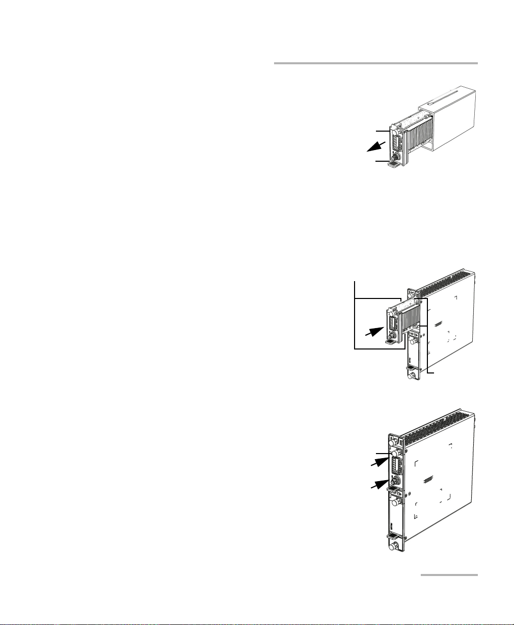
4 Physical Interfaces and LEDs
CFP41 QSFP1 EXT LCK REF OUT SFP+1
1. Laser radiation emitted from this port when LASER LED is on.
1. Laser radiation emitted from this port when LASER LED is on.
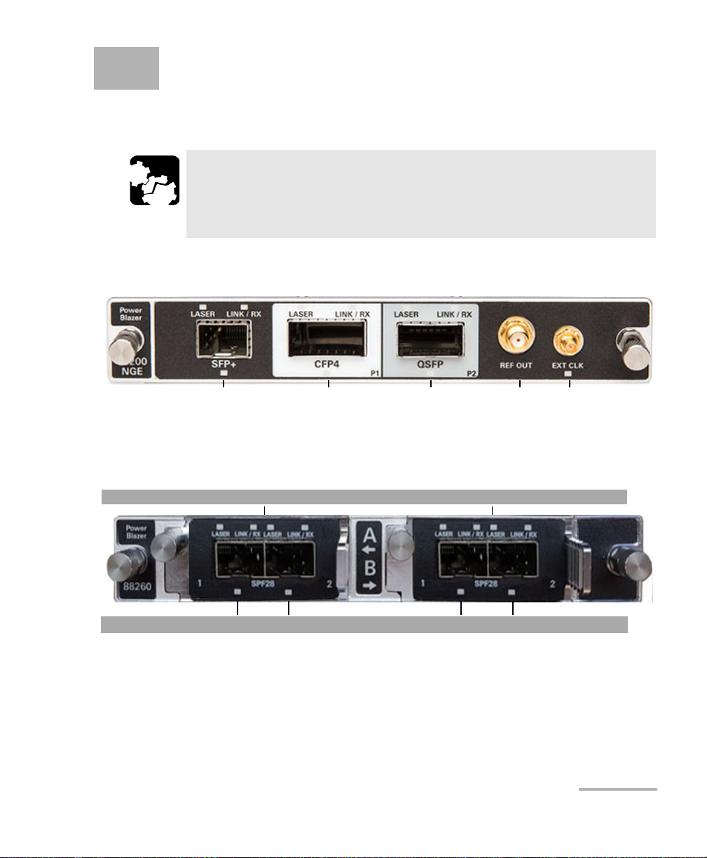
Port A Port B FTBx-88260
Port A1
1
TA-SFP28 Port A21 Port B11 Port B21
This section describes all connectors (ports) and LEDs available on the
88000 Series.
CAUTION
To prevent exceeding the maximum input/output power level,
please refer to this product’s technical specifications at
www.exfo.com.
FTBx-88200NGE
FTBx-88260 and TA-SFP28
Power Blazer 17
Page 30
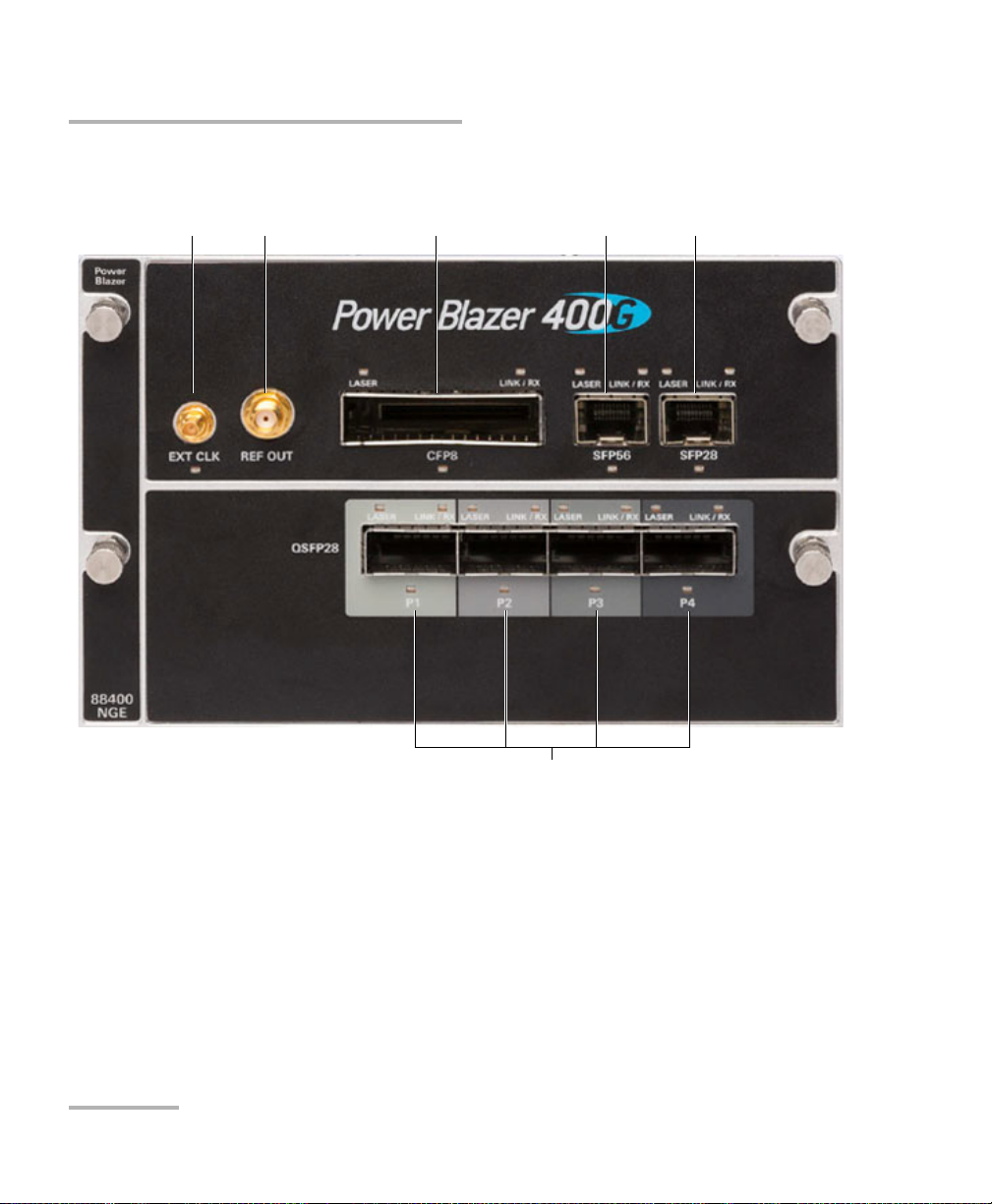
Physical Interfaces and LEDs
QSFP281
1. Laser radiation emitted from this port when LASER LED is on.
EXT CLK REF OUT CFP81 SFP561 SFP281
FTBx-88400NGE
18 88000 Series
Page 31

FTBx-8870/8880
SFP+
1
P2
1. Laser radiation emitted from this port when LASER LED is on.
SFP+
1
P1
RJ45
P1
RJ48C BANTAM BNC
TX/RX2
BNC
RX
DUPLEX
LINK/ACT
LINK/RX
LASER
BNC
EXT CLK
Physical Interfaces and LEDs
Power Blazer 19
Page 32

Physical Interfaces and LEDs
Port Availability on the 88000 Series
Port Availability on the 88000 Series
88200NGE
The following table shows the list of available ports as well as a description
and the signals supported on the module.
Port
Labelled
SFP+ Optical IN/OUT port SFP/SFP+
CFP4 Optical IN/OUT port CFP4
QSFP
(QSFP+ or
QSFP28)
REF OUT Electrical port SMA for eye
EXT CLK Electrical port SMB for
a. Only OTU4 (4 Lanes) and 100GE (4 Lanes) are supported.
b. Only parallel interfaces are supported.
c. Available for Dual Test Set - One-Way Latency measurement mode.
Description Supported Signal(s)
Ethernet 100/1000 Mbit/s, 10 Gbit/s optical
transceiver
transceiver
Optical IN/OUT port QSFP+
transceiver
Optical IN/OUT port QSFP28
transceiver
diagram clock signal
generation
external clock synchronization
a
b
a
Ethernet 10/100/1000 Mbit/s electrical (using active copper SFP)
Fibre Channel 1X, 2X, 4X, 8X, 10X, 16X
CPRI 1.2, 2.4, 3.1, 4.9, 6.1, 9.8 Gbit/s
OBSAI 1.5, 3.1, 6.1 Gbit/s
OC-1/STM-0, OC-3/STM-1, OC-12/STM-4, OC-48/STM-16,
OC-192/STM-64
OTU1, OTU2, OTU1e, OTU2e, OTU1f, OTU2f.
Ethernet 100 Gbit/s
OTU4
Ethernet 40 Gbit/s
OTU3e2, OTU3e1, OTU3
Ethernet 100 Gbit/s
OTU4
DS1/1.5M, E1/2M, 2MHz, 1PPS
c
20 88000 Series
Page 33

Physical Interfaces and LEDs
Port Availability on the 88000 Series
88260
The following table shows the list of Transceiver Adapter (TA) supported on
each port of the FTBx-88260 module.
Port
Labelled
A TA left port TA-SFP28
B TA right port TA-SFP28
Description Supported Transceiver Adapter (TA)
The following table shows the list of port as well as a description and the
signals supported on each Transceiver Adapter (TA).
TA Description
TA-SFP28 Dual SFP28 1 Ethernet 25 Gbit/s optical
a. The ports are listed/referred as follows in the GUI: Port, FTBx-88260‘s port (A or B), TA port (1 or 2), and
connector type; for example Port A1 - SFP28.
Port
Labelled
2
a
Supported Signal(s)
Power Blazer 21
Page 34

Physical Interfaces and LEDs
Port Availability on the 88000 Series
88400NGE
The following table shows the list of available ports as well as a description
and the signals supported on the module.
Port
Labelled
SFP28a
a
Optical IN/OUT port SFP56
SFP56
a
QSFP28
(P1, P2, P3,
and P4)
CFP8 Optical IN/OUT port CFP8
REF OUT Electrical port SMA for eye
EXT CLK
a. Future use.
a
Electrical port SMB for
Description Supported Signal(s)
Optical IN/OUT port SFP28
transceiver
transceiver
Optical IN/OUT port QSFP28
transceiver
transceiver
diagram clock signal
generation
external clock synchronization
Ethernet 100/1000 Mbit/s, 10 Gbit/s, 25 Gbit/s optical
Ethernet 50 Gbit/s
Ethernet 40 Gbit/s, 100 Gbit/s
Ethernet 400 Gbit/s
DS1/1.5M, E1/2M, 2MHz, 1PPS
22 88000 Series
Page 35

Physical Interfaces and LEDs
Port Availability on the 88000 Series
8870/8880
The following table shows the list of available ports as well as a description
and the signals supported for each module.
Connector Labelled Description and supported signal(s)
Bantam BANTAM
TX/RX2
RX
BNC BNC
TX/RX2
BNC
RX
BNC
EXT CLK
RJ45 RJ45 P1 Ethernet 10/100/1000 Mbit/s electrical X X
RJ48C RJ48C DS1/1.5M, E1/2M X X
SFP/SFP+ SFP+ P1
or
SFP+ P2
SFP+ P1 OC-1/STM-0, OC-3/STM-1, OC-12/STM-4, OC-48/STM-16,
SFP+ P2 Ethernet 10/100/1000 Mbit/s electrical (using active copper
TX and RX: DS1/1.5M, E1/2M
RX2: DS1/1.5M
Clock IN/OUT: DS1/1.5M, E1/2M, 2 MHz
TX: E1/2M, E3/34M, DS3/45M, STS-1e/STM-0e/52M, E4/140M,
STS-3e/STM-1e/155M
RX2: DS3, 2 MHz, 10 MHz
Clock OUT: DS1/1.5M, E1/2M, 2 MHz
E1/2M, E3/34M, DS3/45M, STS-1e/STM-0e/52M, E4/140M,
STS-3e/STM-1e/155Mk, 1PPS
Clock IN: DS1/1.5M, E1/2M, 2 MHz, 10 MHz, 1 PPS
Clock IN: DS1/1.5M, E1/2M, 2 MHz, 1 PPS X -
1PPS, 2 MHz, 10 MHz - X
Clock IN: DS1/1.5M, E1/2M, 2 MHz - X
Clock OUT: DS1/1.5M, E1/2M, 2 MHz - X
Ethernet 100 Mbit/s, 1000 Mbit/s,10 Gbit/s LAN/WAN optical
CPRI 1.2, 2.4, 3.1, 4.9, 6.1, 9.8 Gbit/s
OBSAI 1.5, 3.1, 6.1 Gbit/s
Fibre Channel 1X, 2X, 4X, 8X, 10X
OC-192/STM-64
OTU1, OTU2, OTU1e, OTU2e, OTU1f, OTU2f
b
SFP)
a
Module
8870 8880
-X
-X
-X
XX
XX
XX
a. Port SFP+ P2 is used with OC-192/STM-64 in Decoupled (TX≠RX) mode.
b. Available as a second port when the test application requires two ports.
Power Blazer 23
Page 36

Physical Interfaces and LEDs
Transceivers
Transceivers
Carefully connect optical fibre cables to the transceiver IN and OUT ports.
To ensure good signal quality, make sure that the optical fibre connector is
fully inserted into the optical connector port.
To prevent exceeding the maximum input power level please use an
attenuator when a loopback configuration is used.
Before inserting an optical module into the interface receptacle,
inspect the receptacle to make sure nothing is inside.
Use only EXFO supported transceivers. Refer to www.exfo.com for
the list of supported transceivers. Using non-supported transceivers
can affect the performance and accuracy of the test.
CAUTION
CAUTION
WARNING
Note: Do not replace the transceiver while the test is running to avoid distorting
results. First stop the test, replace the transceiver, select the connector type
(refer to Modify Structure Button on page 108), and then restart the test.
RJ45
The electrical port is RJ45 for category 5 unshielded twisted pair (UTP).
Refer to Ethernet Cables on page 708 for cable specifications.
24 88000 Series
Page 37

Physical Interfaces and LEDs
BNC
Connector type is BNC for coaxial 75-ohm cable connection. An adapter
cable (BNC to Bantam) is required for Bantam external clock connection
(not supplied).
SMB
The connector type is SMB for coaxial 75-ohm cable connection. An
adapter cable (SMB to Bantam) is required for Bantam connection (not
supplied).
LEDs
LASER red LED is on when the module is emitting an optical laser
signal.
LINK/RX green LED is on when the link is up, off when the link is down,
and flashing when frames are transmitted and/or received.
BNC
DUPLEX green LED is on for Full Duplex mode, off for Half Duplex
mode, and flashing when collisions are detected.
Port blue LED is on when this port is selected for the test, and flashing
when this port is selected for clock input.
Power Blazer 25
Page 38

Page 39

5 Graphical User Interface
Main
Window
Te st
Control
Tes t M en u
Application
Buttons
Status Bar
Global
Indicator
Title Bar
Overview
This chapter describes the Power Blazer Series graphical user interface.
Main Application Window
The following main application window is displayed when the Power
Blazer application is started.
Main Window
The main window is used to setup a test and to view the test status and
results.
Power Blazer 27
Page 40

Graphical User Interface Overview
Navigation Buttons
Navigation Buttons
Navigation buttons appear when there is not enough room on one page to
display all available test applications. The left and right arrow buttons allow
respectively accessing the previous or next window. The buttons in
between the left and right arrow buttons allow directly selecting the
window for the type of test application listed.
Status Bar
The status bar displays the following information.
Icon
and/or text
Test icon Icon representing the active test application. All
P1, P2, P3, P4 Port identification number: Port x All
A1, A2, B1,
B2
TX/RX, TX, RX Indicates the direction of the signal per port. Transport,
Interface/
Signal
(BTS) or
(RRH)
LINK Green arrow: Link up.
Port identification number composed of the port of the FTBx-88260
module (A or B) and the TA port (1 or 2)
The interface or signal rate per port: 1GE Optical, 40G, OTU1,
OTU2, OTU3, etc.
BTS: Emulation mode is Base Station
RRH: Emulation mode is Remote Radio Head
Red arrow: Link down.
Gray arrow: Awaiting incoming data to provide a status.
Description Test Application
All (FTBx-88260)
Wander (DS1/E1)
All
CPRI/OBSAI BERT
All
CPRI/OBSAI BERT
28 88000 Series
Page 41

Graphical User Interface Overview
Status Bar
Icon
and/or text
Description Test Application
PTP For G.8265.1:
Green arrow: Signaling requests granted.
Red arrow: Request denied, session canceled, or no reply.
Gray arrow: Pending, inactive, or link down.
Refer to Negotiation Status on page 475 for more information.
For G.8275.1:
Green arrow: Announce, Sync, and Follow-up are received according
with their respective interval.
Red arrow: Announce, Sync, or Follow-up are not received.
Gray arrow: Pending.
ESMC Green arrow: ESMC valid information frame received.
Red arrow: No ESMC valid information frames received.
Gray arrow: Pending state.
Refer to ESMC Monitoring on page 321 for more information.
Power level The received optical signal status:
Green with “Power”: Power level in range
Yellow: Power level out-of-range
Red with “LOS”: Loss of signal
b
.
b
a
.
.
Red with “Power”: Power level is close to damage.
Gray: The operational range value is either not available or not
supplied by the transceiver.
Laser ON
b
. The laser icon is not displayed when the laser is offa. The
laser icon is only displayed for optical interfaces. The laser is ON by
default when the test is created. The laser control is not affected when
turning off the laser by generating a LOS for example. Refer to Laser
Button on page 643.
The status of the received signal pattern per port:
Green: Pattern is synchronized.
Red: Loss of pattern.
Gray: Test is not running (EtherBERT test or EoOTN client) or the No
Pattern Analysis (Live) check box is selected.
Connection established between two testing units in Dual Test Set
(DTS), EXFO|Worx Interop, or in Loop Up mode.
Connection not established between two testing units in Dual Test Set
(DTS), EXFO|Worx Interop, or in Loop Up mode.
1588 PTP
SyncE, Wander
All except Cable Test
All
Tra nsp ort
EtherBERT
Fibre Channel
Wireless
Ethernet
Ethernet
Power Blazer 29
Page 42

Graphical User Interface Overview
Status Bar
Icon
and/or text
Description Test Application
Remote unit is busy (locked) in EXFO|Worx Interop operation mode. Ethernet
Loopback Tool enabled on the port unused by the main test
application.
Clock synchronization signal clock. The clock icon is followed by the
clock mode: INT for Internal, EXT for External RCV for Recovered,
or BKP for Backplane. AUTO is displayed for dual port test when a
different clock is used on each port.
Green: Clock Synchronized.
Red: Loss of clock.
Indicates a manual change in the OH bytes transmitted. Not displayed
when using the default OH values.
Remote PC connection established with the Power Blazer. N/A
The test is in loopback mode. Not displayed when not in loopback
mode.
Alarm/error is currently injected. Not displayed when there is no
alarm/error injection.
Ethernet
Tra nsp ort
Ethernet
Fibre Channel
Wireless
Tra nsp ort
NI-CSU Emulation
Tra nsp ort
EtherBERT
Carrier Ethernet OAM
Fibre Channel
Wireless
a. For all lanes for parallel interface.
b. For at least one lane for parallel interface.
The following status are also displayed:
Battery/AC icons, available on FTB platforms, indicate the battery level
and if the platform is connected to an AC power source. Refer to the
platform user guide for more information.
Date and Time indicate the current date and time.
30 88000 Series
Page 43

Graphical User Interface Overview
Global
Alarm
Tes t T i mer
Global indicator area
History
Current
Timer
Global
Verdict
Title Bar
The Title Bar displays the module’s slot number in brackets, the software
application name and the minimize, maximize, and close buttons.
Global Indicator
The global indicator area displays the global pass/fail verdict, global alarm,
and the test duration.
Title Bar
The global indicator area can be maximized for distant viewing. Tap
anywhere within the global indicator area to display a maximized view. Tap
again to exit the maximized view.
Power Blazer 31
Page 44

Graphical User Interface Overview
Global Indicator
Global Verdict
Reports the global test verdict status when supported by the test
application and enabled (when applicable).
Verdict Description
PAS S PA SS is displayed with a green background when all result values meet the configured threshold
criteria.
FAIL FAIL is displayed with a red background when any result value does not meet the configured
threshold criteria or when a specific alarm is detected (refer to each test application for additional
information).
“--” “--” is displayed with a gray background when at least one of the following conditions is met:
- Pass/Fail verdict is not enabled
- there is no defined criterion
- the test has not run yet.
Global Alarm
Indicates the current and history alarm/error status of the test.
Background
color
Gray Current -- No test result available.
Green Current No Alarm No alarm/error has occurred in the last second.
Red Current Alarms or the name of the alarm. An alarm/error occurred in the last second.
Amber History No current alarm/error but at least one
Alarm/
Error
History
History No alarm/error has occurred during the test.
History
Text displayed Description
alarm/error has occurred during the test.
32 88000 Series
Page 45

Graphical User Interface Overview
Test Timer
The test timer without the timer icon indicates the time elapsed since the
beginning of the test. No timer action is active. The test timer format is
“day hour:minute:second”.
Timer
The timer icon with Armed indicates that a start time is active.
The timer icon with the Test Timer indicates that a duration and/or a stop
time is active.
Test Control
Note: Refer to Te st Cont r ol on page 635 for more information.
Test Menu
Test C o n tr ol
The test menu displays the following buttons:
Setup allows configuring the selected test. Refer to Test Setup - Test
Configurator, Timer, and System on page 95 for more information.
Results allows viewing test results. Refer to Test Results on page 341
for more information.
Functions allows configuring additional test functions (refer to Te st
Functions on page 539).
Power Blazer 33
Page 46

Graphical User Interface Overview
Application Buttons
Application Buttons
Help (?) displays the help information related to the content of the
active main window. It is also possible to navigate through the
remainder of the help information.
Exit (x) closes the application.
About (i) mainly displays the product version details and technical
support information.
Module Details button displays the module details such as its ID, Serial
Number, Software Product Version, etc.
View Licence Agreement button displays the details of the product
licence agreement.
Software Options button displays the list of software options.
Note: For information on how to install and activate software options, refer to the
platform User Guide. The Power Blazer application must be restarted once
a new software option is installed in order to activate it.
Software Option Description
10electrical Ethernet 10Base-T electrical interface
100optical Ethernet 100Base-FX optical interface
100electrical Ethernet 100Base-TX electrical interface
GigE_Electrical Ethernet 1000Base-T electrical interface
GigE_Optical Ethernet 1000Base-X optical interface
10G_LAN Ethernet 10G LAN optical interface
10G_WAN Ethernet 10G WAN optical interface
25GE Ethernet 25G
40GE Ethernet 40G
100GE Ethernet 100G
400GE Ethernet 400G
OTU4 Optical Transport Unit-4 (111.81 Gbit/s)
OTU3-e1-e2 Optical Transport Unit-3 Overclocked (44.571/44.583 Gbit/s)
OTU3 Optical Transport Unit-3 (43.018 Gbit/s)
34 88000 Series
Page 47

Graphical User Interface Overview
Application Buttons
Software Option Description
OTU2-1f-2f Optical Transport Unit-2 Overclocked (11.270/11.317 Gbit/s)
OTU2-1e-2e Optical Transport Unit-2 Overclocked (11.049/11.096 Gbit/s)
OTU2 Optical Transport Unit-2 (10.7 Gbit/s)
OTU1 Optical Transport Unit-1 (2.7 Gbit/s)
40G 39.81312 Gbit/s (SONET/SDH)
9953M 9.953 Gbit/s (SONET/SDH)
2488M 2.488 Gbit/s (SONET/SDH)
622M 622 Mbit/s (SONET/SDH)
155M 155 Mbit/s (SONET/SDH)
52M 52 Mbit/s (SONET/SDH)
FC-1X Fibre Channel 1X
FC-2X Fibre Channel 2X
FC-4X Fibre Channel 4X
FC-8X Fibre Channel 8X
FC-10X Fibre Channel 10X
FC-16X Fibre Channel 16X
CPRI-1.2G CPRI 1.2288 Gbit/s
CPRI CPRI 2.4576 Gbit/s and 3.072 Gbit/s
CPRI-4.9G CPRI 4.9152 Gbit/s
CPRI-6.1G CPRI 6.144 Gbit/s
CPRI-9.8G CPRI 9.8304 Gbit/s
DP-CPRI Dual Port CPRI
OBSAI-1.5G OBSAI 1.536 Gbit/s
OBSAI OBSAI 3.072 Gbit/s
OBSAI-6.1G OBSAI 6.144 Gbit/s
ETH-CAPTURE Ethernet Frame Capture
ETH-OAM Carrier Ethernet OAM test application
TRAFFIC-SCAN Traffic Scan
LINK-OAM Link OAM
TST-OAM Test Over Service OAM
DUAL-PORT Dual Port Test
DP_40-100GE Dual Port at 40/100GE
RFC6349 RFC 6349 test application (up to 10GE)
RFC6349_40-100GE RFC 6349 test application (40/100GE)
RFC6349-EXFOWorx EXFO|Worx Interop Operation Mode
Power Blazer 35
Page 48

Graphical User Interface Overview
Application Buttons
Software Option Description
DTS-NAT NAT traversal for DTS applications
ADV-FILTERS Advanced filtering
MPLS MPLS Encapsulation (up to 10GE)
MPLS_40-100GE MPLS Encapsulation (40/100GE)
EoE Ethernet over Ethernet Encapsulation (up to 10GE)
EoE_40-100GE Ethernet over Ethernet Encapsulation (40/100GE)
PBBTE Provider Backbone Bridge Encapsulation (up to 10GE)
PBBTE_40-100GE Provider Backbone Bridge Encapsulation (40/100GE)
IPv6 Internet Protocol Version 6 (IPv6) (up to 10GE)
IPv6_40-100GE Internet Protocol Version 6 (IPv6) (40/100GE)
ODU0 OTN ODU0
ODUMUX ODU Multiplexing Payload Type 20 and 21
EoOTN Ethernet over Optical Transport Network
ODUflex OTN ODUflex
SONET Synchronous Optical Network
SDH Synchronous Digital Hierarchy
OTN-INTR-THRU OTN Intrusive Through Mode
SONETSDH-INTR-THRU SONET/SDH Intrusive Through Mode
MULTI-CH-OTN Multi-Channel OTN Test Application
OTN-MIX-MAPPING Mix-Mapping capability for Multi-Channel OTN
GCC-BERT GCC BERT
TCM Tandem Connection Monitoring STS/AU and VT/TU (SONET/SDH)
ETH-THRU Through Mode Test Application
iOptics Intelligent Pluggable Optic Test Application
iSAM Intelligent Service Activation Methodology
CABLE_TEST Cable Test Application
1588PTP 1588 Precision Time Protocol Test Application
G82751 ITU-T G.8275.1 Profile
SyncE Synchronous Ethernet Test Application
Wander Time Error / Wander Test Application
TCP-THPUT TCP Throughput Test Application
DSn Digital Signal
DS1-FDL DS1/1.5M Facility Data Link
DS3-FEAC DS3/45M Far-End Alarm and Control
DUALRX Dual RX
36 88000 Series
Page 49

Graphical User Interface Overview
Moves to the top of the list.
Moves one page up.
Moves one line up.
Moves one line down.
Moves one page down.
Moves to the end of the list.
Software Option Description
DS3-G747 ITU-T Recommendation G.747
PDH Plesiochronous Digital Hierarchy
NI-CSU NI/CSU Emulation
Zoomed-In/Zoomed-Out Views
Some configuration and result blocks give access to zoomed views
allowing more detailed configurations/results.
The block title contains the magnifier (+) icon when a zoomed view is
available.
To zoom-in, tap the magnifier (+) icon or anywhere on the block.
To zoom-out, tap on the magnifier (-) icon or anywhere on the block title.
Arrow Buttons
Zoomed-In/Zoomed-Out Views
Power Blazer 37
Page 50

Graphical User Interface Overview
Keyboard Usage
Keyboard Usage
The GUI pops up different keyboards to modify data. Following are the
usual keyboard keys:
Left arrow moves the cursor one position to the left.
Right arrow moves the cursor one position to the right.
Up arrow increases the value by one.
Down arrow decreases the value by one.
Del deletes the value at the cursor position.
Back deletes the value preceding the cursor position.
OK completes data entry.
Cancel closes the keyboard and discards the keyboard entry.
Previous... allows the selection of previously configured values. This
button is only available for certain fields like IP Address, MAC Address,
etc.
Note: For certain text fields, the GUI pops up or uses the unit’s on-screen
keyboard. Refer to the platform user guide for more information on how to
use it.
For full keyboard, the Back, Del, Shift, and Space bar keys have the same
functionality as a regular PC keyboard.
38 88000 Series
Page 51

Graphical User Interface Overview
Keyboard Usage
For multiplexing keyboard, tap on all mapped signals that have to be
added/removed to/from the test path.
A mapped signal with an orange background color is part of the test
path.
A mapped signal with a gray background color is not part of the test
path.
Power Blazer 39
Page 52

Graphical User Interface Overview
Keyboard Usage
The Trace message keyboard allows entering alphanumerical characters
(ITU T.50) required for J0/J1/J2/TTI Trace fields. Tap the Control
Characters button to access these characters.
ITU T.50 Characters
b7 to b1 Character Description b7 to b1 Character Description
000 0000 NUL Null 001 0000 DLE Data Link Escape
000 0001 SOH Start Of Heading 001 0001 DC1 Device Control 1
000 0010 STX Start of Text 001 0010 DC2 Device Control 2
000 0011 ETX End of Text 001 0011 DC3 Device Control 3
000 0100 EOT End Of Transmission 001 0100 DC4 Device Control 4
000 0101 ENQ Enquiry 001 0101 NAK Negative Acknowledge
000 0110 ACK Acknowledge 001 0110 SYN Synchronous idle
000 0111 BEL Bell 001 0111 ETB End of Transmission Block
000 1000 BS Backspace 001 1000 CAN Cancel
000 1001 HT Horizontal Tabulation 001 1001 EM End of Medium
000 1010 LF Line Feed 001 1010 SUB Substitute character
000 1011 VT Vertical Tabulation 001 1011 ESC Escape
000 1100 FF Form Feed 001 1100 IS4 Information Separator 4
000 1101 CR Carriage Return 001 1101 IS3 Information Separator 3
000 1110 SO Shift-Out 001 1110 IS2 Information Separator 2
000 1111 SI Shift-In 001 1111 IS1 Information Separator 1
40 88000 Series
Page 53

6 Test Setup - Test Applications
The Power Blazer offers the following test applications.
Type Application
Intelligent
Apps
Tra nsport OTN BERT X--X45
Ethernet EtherSAM (Y.1564) X--X59
Sync 1588 PTP X--X75
Fibre Channel FC BERT X--X78
Wireless CPRI/OBSAI BERT X--X79
iOptics X-X X42
iSAM X--X43
Multi-Channel OTN X---44
SONET/SDH BERT X--X50
OTN-SONET/SDH BERT X--X47
DSn/PDH BERT ---X53
SONET/SDH - DSn/PDH BERT ---X55
NI/CSU Emulation ---X58
RFC 6349 X--X63
RFC 2544 XX- X61
EtherBERT XXXX64
Traffic Gen & Mon XX- X66
Smart Loopback XX-X68
Through Mode X - - X 70
TCP Throughput X--X71
Carrier Ethernet OAM X--X72
Cable Test ---X74
SyncE X--X76
Wander ---888077
88200NGE 88260 88400NGE 8870 / 8880
Available on
Page
Power Blazer 41
Page 54

Test Setup - Test Applications
EXFO Module
iOptics
iOptics
iOptics test application provides a quick assessment of the proper
operation of an optical transceiver before using it in a network or test
environment. The validation is done by running sub-tests in addition to
monitoring transceiver power consumption and temperature. Result and
verdict are reported for each sub-test and monitoring task. Transceiver’s
manufacturing information is also automatically collected.
A fiber loopback patch cord is required to perform the test with applicable
attenuation included to protect the optical device. Bidirectional (single
fiber) transceivers are not supported since the iOptics test requires a
loopback.
Typical iOptics test application:
Supported Interfaces/Rates: 40G/100G/OTU3/OTU3e1/OTU3e2/OTU4
parallel interfaces and all serial interfaces up to 10G/OTU2f (refer to
Rate on page 245 for more information).
42 88000 Series
Page 55

Test Setup - Test Applications
Network
under test
(EVC)
Local Unit Remote Unit
EXFO Module EXFO Module
Manual or
Remote
Loopback
Network
under test
(EVC)
Local Unit Remote Unit
EXFO Module EXFO Module
EtherSAM
(DTS)
iSAM
iSAM is a simplified version of EtherSAM that is centered around addressing
turn-up of E-Line circuits (EVC). The objective of the test is to validate
Carrier Ethernet-based services key performance indicators defined in
MEF: Frame Delay (FD), Inter-Frame Delay Variation (IFDV), and Frame
Loss Ratio (FLR). In addition the RFC 6349 subtest can be enabled to
validate that the Ethernet service is able to properly carry TCP traffic.
The iSAM test has to be executed in conjunction with a remote module.
The remote module can be either in loopback configuration for
unidirectional testing or in EtherSAM Dual Test Set mode for bidirectional
testing.
The Dual Test Set test allows bi-directional testing between two
compatible modules providing independent results for each test direction.
The results from local-to-remote and remote-to-local are available on the
local testing unit.
iSAM
Typical iSAM test applications:
Supported Interfaces/Rates: 10M to 100G.
Power Blazer 43
Page 56

Test Setup - Test Applications
Network
under test
Testing Unit DUT Loopback
EXFO Module
Network
under test
Te s t ing U n it Te s t ing U n it
EXFO Module EXFO Module
Multi-Channel OTN
Multi-Channel OTN
The Multi-Channel OTN test application validates individual channel
connectivity with a device under test by allowing concurrent generation
and monitoring of all channels of a single or mixed ODUmux test structure.
Typical Multi-Channel OTN test applications:
Path/Mapping
The Multi-Channel OTN test application offers the following
path/mapping structures depending on the inserted CFP4/QSFP
transceivers and enabled options. Mixed mapping is available with the
OTN-MIX-MAPPING software option.
44 88000 Series
Page 57

Test Setup - Test Applications
Network
under test
Testing Unit DUT Loopback
EXFO Module
Network
under test
Te s t ing U n it Te s t ing U n it
EXFO Module EXFO Module
Testing Unit
EXFO Module
Network
under test
Network
under test
OTN BERT
Allows OTN (framed and unframed), OTN multiplexing, and EoOTN traffic
generation with specific test pattern for Bit Error Rate analysis.
Typical OTN BERT test applications:
OTN BERT
Path/Mapping
The OTN BERT test application offers the following path/mapping
structures depending on the inserted transceiver and enabled options.
For 88200NGE (up to OTU4) and 8870/8880 (up to OTU2f)
Power Blazer 45
Page 58

Test Setup - Test Applications
OTN BERT
46 88000 Series
Page 59

Test Setup - Test Applications
Network
under test
Testing Unit DUT Loopback
EXFO Module
Network
under test
Te s t ing U n it Te s t ing U n it
EXFO Module EXFO Module
Testing Unit
EXFO Module
Network
under test
Network
under test
OTN-SONET/SDH BERT
OTN-SONET/SDH BERT
Allows the validation of the SONET/SDH embedded in OTN transport
protocol by performing a BERT test to check the traffic or payload stability
over a network facility.
Typical OTN-SONET/SDH BERT test applications:
Power Blazer 47
Page 60

Test Setup - Test Applications
OTN-SONET/SDH BERT
Path/Mapping
The OTN-SONET/SDH BERT test application offers the following
path/mapping structures depending on the inserted transceiver and
enabled options.
For OTN-SONET BERT: up to OTU4 for 88200NGE and up to OTU2 for
8870/8880.
48 88000 Series
Page 61

Test Setup - Test Applications
OTN-SONET/SDH BERT
For OTN-SDH BERT: up to OTU4 for 88200NGE and up to OTU2 for
8870/8880.
Power Blazer 49
Page 62

Test Setup - Test Applications
Network
under test
Testing Unit DUT Loopback
EXFO Module
Network
under test
Te s t ing U n it Te s t ing U n it
EXFO Module EXFO Module
Testing Unit
EXFO Module
Network
under test
Network
under test
SONET/SDH BERT
SONET/SDH BERT
Allows the validation of the SONET or SDH transport protocol by
performing a BERT test to check the traffic or payload stability over a
network facility.
Typical SONET/SDH BERT test applications:
50 88000 Series
Page 63

Test Setup - Test Applications
SONET/SDH BERT
Path/Mapping
The SONET/SDH BERT test application offers the following
path/mapping structures depending on the inserted transceiver, and
enabled options.
For SONET B E RT
Power Blazer 51
Page 64

Test Setup - Test Applications
SONET/SDH BERT
For SDH BERT
52 88000 Series
Page 65

Test Setup - Test Applications
Network
under test
Testing Unit DUT Loopback
EXFO Module
Network
under test
Te s t ing U n it Te s t ing U n it
EXFO Module EXFO Module
DSn/PDH BERT
DSn/PDH BERT
Allows validation of the DSn or PDH transport protocol by performing a
BERT test to check the traffic or payload stability over a network facility.
Typical DSn/PDH BERT test applications:
Power Blazer 53
Page 66

Test Setup - Test Applications
DSn/PDH BERT
Path/Mapping
The DSn/PDH BERT test application offers the following path/mapping
structures depending on model and enabled options.
For DSn:
Note: It is possible to enable DS0/E0 from Signal - Signal Configuration (DSn/PDH)
on page 294.
For PDH:
Note: It is possible to enable E0 from Signal - Signal Configuration (DSn/PDH) on
page 294.
54 88000 Series
Page 67

Test Setup - Test Applications
Network
under test
Testing Unit DUT Loopback
EXFO Module
Network
under test
Te s t ing U n it Te s t ing U n it
EXFO Module EXFO Module
Testing Unit
EXFO Module
Network
under test
Network
under test
SONET/SDH - DSn/PDH BERT
SONET/SDH - DSn/PDH BERT
Allows validation of the DSn or PDH embedded in SONET or SDH transport
protocol by performing a BERT test to check the traffic or payload stability
over a network facility.
Typical SONET/SDH - DSn/PDH BERT test applications:
Power Blazer 55
Page 68

Test Setup - Test Applications
SONET/SDH - DSn/PDH BERT
Path/Mapping
The SONET/SDH - DSn/PDH BERT test application offers the following
path/mapping structures depending on the model and enabled
options.
For SONET:
56 88000 Series
Page 69

For SDH:
Test Setup - Test Applications
SONET/SDH - DSn/PDH BERT
Power Blazer 57
Page 70

Test Setup - Test Applications
Network
under test
Te s t H ea d
NI/CSU Emulation
EXFO Module
Network
under test
Testing Unit NI/CSU Emulation
EXFO Module
DSn/PDH BERT
EXFO Module
NI/CSU Emulation
NI/CSU Emulation
Allows DS1 testing in NI/CSU (Network Interface/Customer Service Unit)
emulation mode.
Typical NI/CSU Emulation test applications:
58 88000 Series
Page 71

Test Setup - Test Applications
EtherSAM (Y.1564)
EtherSAM (Y.1564)
EtherSAM can simulate all types of services that will run on the network
and simultaneously qualify all key SLA parameters for each of these
services. Moreover, it validates the QoS mechanisms provisioned in the
network to prioritize the different service types, resulting in more accurate
validation and much faster deployment and troubleshooting.
The EtherSAM (Y.1564) test, in single port configuration, has to be
executed in conjunction with a remote module. The remote module can
be either in loopback configuration for unidirectional testing or in
EtherSAM Dual Test Set mode for bidirectional testing.
The Dual Test Set test allows bi-directional testing between two
compatible modules providing independent results for each test direction.
The results from local-to-remote and remote-to-local are available on the
local testing unit.
The Dual Port topology allows simultaneous and bidirectional traffic
generation and analysis at 100 percent wire-speed at any packet size.
Power Blazer 59
Page 72

Test Setup - Test Applications
Network
under test
Testing Unit Loopback Unit
EXFO Module EXFO Module
Network
under test
Testing Unit Remote Unit
EXFO Module EXFO Module
Network
under test
Testing Unit
EXFO Module
EtherSAM (Y.1564)
Typical EtherSAM (Y.1564) test applications:
Supported Interfaces/Rates: 10M to 100G. Dual Port topology is only
available for rates up to 10G WAN.
60 88000 Series
Page 73

Test Setup - Test Applications
RFC 2544
RFC 2544 allows Ethernet Throughput, Back-to-Back, Frame Loss, and
Latency performance testing in accordance with RFC 2544 specifications.
The RFC 2544 test, in single port configuration, has to be executed in
conjunction with a remote module. The remote module can be either in
loopback configuration for unidirectional testing or in RFC 2544 Dual Test
Set mode for bidirectional testing.
The Dual Test Set test allows bi-directional testing between two
compatible modules providing independent results for each test direction.
The results from local-to-remote and remote-to-local are available on the
local testing unit.
The Dual Port topology allows simultaneous and bidirectional traffic
generation and analysis at 100 percent wire-speed at any packet size.
RFC 2544
Power Blazer 61
Page 74

Test Setup - Test Applications
Network
under test
Testing Unit Loopback Unit
EXFO Module EXFO Module
Network
under test
Testing Unit Remote Unit
EXFO Module EXFO Module
Network
under test
Testing Unit
EXFO Module
RFC 2544
Typical RFC 2544 test applications:
Supported Interfaces/Rates: 10M to 100G. Dual Port topology is only
available for rates up to 10G WAN.
62 88000 Series
Page 75

Test Setup - Test Applications
EVC
Testing Unit Remote Unit
EXFO Module
EXFO Module
including BV Units
RFC 6349
RFC 6349 is used to confirm that the Ethernet service is able to properly
carry TCP traffic.
The RFC 6349 test has to be executed in conjunction with a remote
compatible module in RFC 6349 Dual Test Set or EXFO
operation mode allowing bidirectional testing. The test provides
independent results for each test direction. The results from
local-to-remote and remote-to-local are available on the local testing unit.
Typical RFC 6349 test application:
Supported Interfaces/Rates: 10M to 10G LAN, 40G and 100G.
|Worx Inter o p
RFC 6349
Power Blazer 63
Page 76

Test Setup - Test Applications
Network
under test
Testing Unit Loopback Unit
EXFO Module EXFO Module
Network
under test
Testing Unit Testing Unit
EXFO Module EXFO Module
Network
under test
Testing Unit
EXFO Module
Network
under test
Testing Unit
EXFO Module
Testing Units
EXFO Module
EtherBERT
EtherBERT
Allows Ethernet Layer 1 up to Layer 4 and Unframed Layer 1 traffic
generation with specific test pattern for Bit Error Rate analysis.
Typical EtherBERT test applications:
64 88000 Series
Page 77

Test Setup - Test Applications
Network
under test
Testing Unit
EXFO Module
Loopback Units
EXFO Module
EtherBERT
Supported Interfaces/Rates: 10M to 400G. Dual Port topology is
available for either rates up to 10G WAN or for rates 40/100G.
Power Blazer 65
Page 78

Test Setup - Test Applications
Network
under test
Testing Unit Loopback Unit
EXFO Module EXFO Module
Network
under test
Testing Unit Testing Unit
EXFO Module EXFO Module
Network
under test
Testing Unit
EXFO Module
Network
under test
Testing Unit
EXFO Module
Testing Units
EXFO Module
Traffic Gen & Mon
Traffic Gen & Mon
Allows Ethernet traffic generation and analysis of up to 16 streams.
Typical Traffic Gen & Mon test applications:
66 88000 Series
Page 79

Test Setup - Test Applications
Network
under test
Testing Unit
EXFO Module
Loopback Units
EXFO Module
Traffic Gen & Mon
Supported Interfaces/Rates: 10M to 100G. Dual Port topology is only
available for rates up to 10G WAN.
Power Blazer 67
Page 80

Test Setup - Test Applications
Network
under test
Testing Unit Smart Loopback Unit
EXFO Module EXFO Module
Smart Loopback
Smart Loopback
Allows transmitting back the received Ethernet stream of data while
interchanging the source and destination MAC addresses, IP addresses,
and/or UDP/TCP ports. However in Transparent (Pseudo-Physical) mode
the Smart Loopback operates as a physical loopback by transmitting all
received frames unaltered and without discrimination.
The Smart Loopback test can be created locally (refer to Ethernet Test
Applications on page 87) or remotely using an EXFO unit (refer to Discover
Remote Button on page 636) or a Third-Party device (see Third-Party
Remote Loopback on page 69).
Typical Smart Loopback test application:
Supported Interfaces/Rates: 10M to 100G.
68 88000 Series
Page 81

Test Setup - Test Applications
Smart Loopback
Third-Party Remote Loopback
The Third-party Remote Loopback feature provides the capability to be
discovered and react to loop-up and loop-down commands from a third
party device. This feature is used for unidirectional testing, where the test
stream is transmitted from the third party device to a remote EXFO device.
The looped back test stream is received and analyzed by the third-party
device.
The third-party loopback supports three level of messages:
Layer 2: Only MAC addresses are swapped.
Layer 3: MAC and IP addresses are swapped.
Layer 4: MAC and IP addresses are swapped along with the UDP port.
To emulate a third-party remote device, the loopback mode is set in the
function of the layer of loop messages received. The loop messages are:
Layer 2: Ethernet
Layer 3: IP
Layer 4: UDP/TCP
On receipt of the third-party loop-up command as per requested layer, the
loopback mode is set and initiated on the module.
Power Blazer 69
Page 82

Test Setup - Test Applications
Tes t i ng U nit
in Through Mode
Network Ethernet Network Ethernet
EXFO Module
Through Mode
Through Mode
The Through Mode test application allows traffic to pass through the
module using two electrical or optical ports for in-service troubleshooting
of live traffic between the carrier/service provider network and the
customer’s network.
Typical Through Mode test application:
Supported Interfaces/Rates: 10M to 10GE LAN, and 100GE;
10/100/1000M electrical is supported when using an active copper SFP
and the RJ45 port.
70 88000 Series
Page 83

Test Setup - Test Applications
Network
under test
Local Testing Unit Remote Unit
EXFO Module EXFO Module
TCP Throughput
TCP Throughput
The objective of this test is to find the TCP throughput based on the
successfully transported bytes over the test time. Two units running a TCP
Throughput test are required. One unit will act as the source (Local) and
the other one as the destination (Remote).
The local unit starts sending TCP segments using the Initial Window Size
defined. The window size is adjusted following the TCP algorithm. The
window size is incremented until the Maximum Window Size or
congestion is reached. However, the window size will be reduced when
congestion occurs, then incremented again as described above when the
congestion is cleared. TCP Throughput and windows size statistics will be
gathered throughout the test.
Typical TCP Throughput test application:
Supported Interfaces/Rates: 10M to 1G.
Power Blazer 71
Page 84

Test Setup - Test Applications
MIP
EXFO Module Peer MEP
Local MEP
MIP
EXFO Module
Local MEP
EXFO Module
Smart Loopback with
S-OAM Responder enabled.
Carrier Ethernet OAM
Carrier Ethernet OAM
The Carrier Ethernet OAM test application supports the following tests:
Ethernet OAM (S-OAM), MPLS-TP OAM, and Link OAM.
Ethernet OAM and MPLS TP OAM
The Ethernet Service OAM tests are divided into two main categories:
Performance Monitoring measures parameters such as frame delay,
frame loss, and synthetic loss (Y.1731/MEF).
Connectivity Fault Management provides the capability for detecting,
verifying, and isolating connectivity failure (Y.1731/802.1ag/MEF).
Typical Ethernet OAM and MPLS TP OAM test applications:
Supported Interfaces/Rates: 10M to 10G LAN/WAN.
72 88000 Series
Page 85

Test Setup - Test Applications
EXFO Module NID/Switch
Testing Equipment
Carrier Ethernet OAM
Link OAM
The Link OAM test validates the Link OAM protocol capabilities and the
Ethernet link connection of a remote equipment.
Typical Link OAM test application:
Supported Interfaces/Rates: 10M to 10G LAN/WAN.
Power Blazer 73
Page 86

Test Setup - Test Applications
Testing Unit
Far end equipment
EXFO Module
UTP cable
Testing Unit
Unplugged cable
EXFO Module
UTP cable
Cable Test
Cable Test
The cable test application is used to diagnose un-shielded twisted pairs
(UTP) cables (up to Category 6e/Class E).
Cable test can be performed everywhere in the network where an
electrical 10/100/1000 Mbit/s Ethernet interface is available for testing. Only
the pairs used by the Ethernet signal will be tested. For 10 Base-T, and
100 Base-TX, pair 2 and 3 will be tested; for 1000 Base-T, all pairs will be
tested. However, if the Ethernet signal is unknown, all four pairs will be
tested.
Even if a link up is not required when testing with a far end equipment, it is
preferable to have the far end equipment powered up to maximize the
cable test results.
Supported Ethernet cable categories are: Category 3/Class C, Category 4,
Category 5, Category 5e/Class D, and Category 6e/Class E.
Note: Cable test result is reliable for cable length of 10 meters to 120 meters
(32.81 feet to 393.7 feet).
Typi c al Ca b le Tes t appli catio ns:
Supported Interfaces/Rates: 10M to 1000M Electrical.
74 88000 Series
Page 87

Test Setup - Test Applications
Network
under test
Te s t ing U n it GM C loc k
EXFO Module Grand Master Clock Source
1588 PTP
The 1588 PTP (Precision Time Protocol) test application handles the
1588 PTP communication with the Grand Master (GM) clock, collects
statistics related to packets, and monitors the clock Quality Level.
Typical 1588 PTP test application:
Supported Interfaces/Rates: 10M to 10G LAN.
1588 PTP
Power Blazer 75
Page 88

Test Setup - Test Applications
Network
under test
Testing Unit Network Equipment
EXFO Module EEC
EXFO Module
Network
under test
Testing Unit
EXFO Module
Testing Unit
SyncE
SyncE
The Synchronous Ethernet (SyncE) test application provides elementary
test primitives to interactively validate the clock management functions of
a SyncE capable network equipment.
Typical SyncE test applications:
Supported Interfaces/Rates: 100M to 10G LAN.
76 88000 Series
Page 89

Test Setup - Test Applications
Network
under test
Testing Unit
EXFO Module
Wander
The Wander application provides data acquisition and processing
capabilities to quantify and validate the Time Error / Time Interval Error of a
synchronization equipment.
Time Error is defined as the difference between the time reported by a
clock signal under test and the time reported by a reference clock.
Typical Wander test applications:
Supported Interfaces/Rates: 100/1000M Electrical, 10GE LAN,
1GE Optical, 100M Optical, DS1, E1, 2 MHz, 10 MHz, and 1PPS.
Wand er
Note: Only one instance of the Wander application is allowed on a platform due
to high processing activity related to MTIE calculation.
Note: The Wander test automatically stops when one of the following alarms
occur: LOS, OOF (DS1), LOF (E1), AIS (DS1/E1), or REF-FAULT.
Power Blazer 77
Page 90

Test Setup - Test Applications
Network
under test
Testing Unit DUT Loopback
EXFO Module
Network
under test
Testing Unit Testing Unit
EXFO Module EXFO Module
FC BERT
FC BERT
The FC BERT (Fibre Channel BERT) application provides full wire-speed
traffic generation at the FC-2 layer allowing BER testing for link integrity
measurements, latency, buffer-to-buffer credit measurements for
optimization as well as login capabilities.
Typical Fibre Channel BERT test applications:
Supported Interfaces/Rates: 1X, 2X, 4X, 8X, 10X, 16X.
78 88000 Series
Page 91

Test Setup - Test Applications
CPRI/OBSAI BERT
CPRI/OBSAI BERT
The CPRI/OBSAI BERT test application offers the capability to test the
fronthaul and dark fiber for Unframed rates and Framed L2 protocol, round
trip delay, and Service Disruption Time measurements.
The Common Public Radio Interface (CPRI) is an industry cooperation
aimed at defining a publicly available specification for the key internal
interface of radio base stations between the Radio Equipment Control
(REC) and the Radio Equipment (RE). In the industry the CPRI REC and RE
are mainly known as Base Station (BTS) and Remote Radio Head (RRH)
respectively.
The Open Base Station Architecture Initiative (OBSAI) separates a
traditional radio base station configuration into a Base Transceiver Station
(BTS) and a Remote Radio Head (RRH). The BTS processes the digital
baseband radio information and performs the control of the RRH. The RRH
converts the digital radio information into radio frequency signals
transported over the air interface (antenna).
Power Blazer 79
Page 92

Test Setup - Test Applications
Network
under test
Testing Unit Testing Unit
EXFO Module
Unframed,
Framed L2
EXFO Module
Network
under test
Testing Unit Physical Loopback
EXFO Module
Unframed
Network
under test
Base Station (BTS)
EXFO Module
Framed L2
RRH or
EXFO Module
Network
under test
Testing Unit
EXFO Module
Testing Units
EXFO Module
CPRI/OBSAI BERT
Typical CPRI/OBSAI BERT test applications:
Note: A RRH is typically not capable to perform a loopback of the traffic so BERT
test monitoring is not applicable. The BERT test is more common when
testing between two test units.
Additional CRPI BERT test application:
Supported Interfaces/Rates:
CPRI: 1.2, 2.4, 3.1, 4.9, 6.1, and 9.8 Gbit/s
OBSAI: 1.5, 3.1, and 6.1 Gbit/s.
80 88000 Series
Page 93

7 Selecting and Starting a Test
Tes t S e que n c e
Block
Optical Device
Under Test Block
A test can be created either by selecting the test from the Test Applications
tab or by loading a previously saved configuration (refer to Save/Load
Button on page 653 for more information).
Intelligent Apps
iOptics
To select, configure, and start iOptics:
1. From the test menu, tap Setup.
2. From the Test Applications tab, under Intelligent Apps, tap the
iOptics icon.
3. From the Test Configurator tab select the interface/port and its rate.
Power Blazer 81
3a. From the Optical Device Under Test block, tap the desired port
icon.
3b. Once the transceiver is correctly detected , select its rate.
3c. From the Te s t Seq u ence block, select the test parameters and
thresholds (refer to Test Sequence (iOptics) on page 329).
Note: The iOptics test application uses Internal timing for clock synchronization.
Page 94

Selecting and Starting a Test
Intelligent Apps
4. Ensure the laser is ON and tap the Start button from the right
navigation bar to start the test (refer to Start/Stop|TX Button on
page 657). The Summary result page will be automatically displayed
when the test is started. For additional results refer to Test Results on
page 341. The test automatically stops when the transceiver is invalid
or missing.
5. When the test ends automatically or is manually stopped, the generate
report pop-up is displayed by default. If required, tap Yes to generate a
report of the test results and statistics (refer to Report Button on
page 647 for more information).
82 88000 Series
Page 95

Selecting and Starting a Test
Remote
Operation Mode
Remote BlockLocal Block
Network Block
Intelligent Apps
iSAM
To select, configure, and start iSAM:
1. From the test menu, tap Setup.
2. From the Test Applications tab, under Intelligent Apps, tap the iSAM
icon.
3. From the Test Configurator tab configure the interface structure and
its parameters.
3a. From the Local block, either select the basic port parameters or
click on More for all settings (refer to Local Details (iSAM) on
page 200). Ensure that the link is up and the power level for
optical interface (when supported) is adequate in the status bar
before proceeding to the next step (refer to Status Bar on
page 28).
For CFP/QSFP interface rates, check for the optical validation
check mark indicating that the transceiver matches the
configured interface/rate (refer to Physical Interface Port - Test
Configurator Overview on page 100).
Power Blazer 83
Page 96

Selecting and Starting a Test
Intelligent Apps
3b. From the Network block, either select the basic test parameters
or click on More for all settings (refer to Network Details (iSAM)
on page 226). The total bandwidth and the estimated test duration
are displayed.
3c. Select the remote operation mode; DTS is automatically selected
when the RFC 6349 Test is enabled:
3d. From the Remote block, either select the basic remote
parameters or click on More for all settings (refer to Remote
Details (iSAM) on page 248).
DTS (Dual Test Set)
The remote device is automatically set in EtherSAM when the
connection/overtake is successfully established.
Remote Loopback
The remote device is automatically set in Smart Loopback when the
connection/overtake is successfully established.
Manual Loopback
The remote device is a physical loopback or has to be manually set in
loopback.
Note: The iSAM test application uses Internal timing for clock synchronization.
4. Ta p the Start button from the right navigation bar to start the test (refer
to Start/Stop|TX Button on page 657). If the connection with the
remote module is not established with either DTS or Remote
Loopback mode, the automatic remote connection process is
performed before starting the test. The Summary result page will be
automatically displayed when the test is started from any Setup
configuration page. For additional results refer to Test Results on
page 341.
5. When the test ends automatically or is manually stopped, the generate
report pop-up is displayed by default. If required, tap Yes to generate a
report of the test results and statistics (refer to Report Button on
page 647 for more information).
84 88000 Series
Page 97

Selecting and Starting a Test
Modify Structure
Protocol Block
Te s t Blo c k
Clock Block
Interface Block
Physical
Interface Port
Transport Test Applications
Transport Test Applications
To select, configure, and start a Transport test:
1. From the test menu, tap Setup.
2. From the Test Applications tab, under Transport, tap a test icon.
3. From the Test Configurator tab configure the signal structure and its
parameters.
3a. Ta p the Modify Structure button to set the basic structure of the
test such as the interface/rate, connector, etc. (refer to Modify
Structure Button on page 108).
3b. For CFP/QSFP interface, check for the optical validation check
mark indicating that the transceiver matches the configured
interface/rate (refer to Physical Interface Port - Test Configurator
Overview on page 100).
3c. Tap the interface block to configure the signal parameters (refer
to page 95).
3d. For an embedded signal, tap the protocol block to configure the
signal (refer to page 95).
Power Blazer 85
Page 98

Selecting and Starting a Test
Transport Test Applications
3e. Tap the test block to configure the specific test settings (refer to
page 95). Not available with NI/CSU Emulation test application.
3f. Tap the clock block to configure the clock synchronization (refer
to Clock on page 148).
4. Ta p the Timer tab to automatically start and/or stop the test at a given
time or for a specific duration (refer to Timer on page 330).
5. For additional test configurations refer to Test Functions on page 539.
6. Ta p the Start button from the right navigation bar to start the test. (refer
to Start/Stop|TX Button on page 657). The Summary result page will
be automatically displayed when the test is started from any Setup
configuration page. For additional results, refer to Test Results on
page 341.
7. Ta p the Stop button to stop the test. By default the generate report
pop-up is displayed. If required, tap Yes to generate a report of the test
results and statistics (refer to Report Button on page 647).
86 88000 Series
Page 99

Selecting and Starting a Test
Modify Structure
Protocol Block
Te s t Blo c k
Clock Block
Interface Block
Physical
Interface Port
Ethernet Test Applications
Ethernet Test Applications
To select, configure, and start an Ethernet test:
1. From the test menu, tap Setup.
2. From the Test Applications tab, under Ethernet, tap a test icon.
3. From the Test Configurator tab configure the interface structure and
its parameters.
3a. Ta p the Modify Structure button to set the basic structure of the
test such as the interface/rate, connector, etc. (refer to Modify
Structure Button on page 108).
3b. For CFP4/CFP8/QSFP interface, check for the optical validation
check mark indicating that the transceiver matches the
configured interface/rate (refer to Physical Interface Port - Test
Configurator Overview on page 100).
3c. Tap the interface block to configure the interface parameters
(refer to page 95). For Dual Port topology, there is an interface
block for each port. Ensure that the link is up and the power level
(when supported) is present in the status bar before proceeding
to the next step (refer to Status Bar on page 28).
Power Blazer 87
Page 100

Selecting and Starting a Test
Ethernet Test Applications
3d. Tap the protocol block1 to configure the frame structure and its
parameters (refer to page 97). For RFC 2544, EtherBERT, and
Traffic Gen & Mon in Dual Port topology, there is a protocol block
for each port.
3e. Tap the test block
page 97).
3f. Tap the clock block
to Clock on page 148).
4. Ta p the Timer tab to automatically start and/or stop the test at a given
time or for a specific duration (refer to Timer on page 330).
5. For additional test configurations refer to Test Functions on page 539.
6. Ta p the Start button from the right navigation bar to start the test (refer
to Start/Stop|TX Button on page 657). The Summary result page will
be automatically displayed when the test is started from any Setup
configuration page. For additional results refer to Test Results on
page 341.
2
to configure the specific test settings (refer to
3
to configure the clock synchronization (refer
7. Depending on the test, when the test ends automatically or is manually
stopped, the generate report pop-up is displayed by default. If required,
tap Yes to generate a report of the test results and statistics (refer to
Report Button on page 647 for more information).
1. Not available with Smart Loopback, Through Mode, TCP Throughput, Carrier Ethernet OAM, and Cable Test.
2. Not available with Traffic Gen & Mon and Through Mode.
3. Not available with
clock is either set to
Dual Port
Internal
88 88000 Series
topology, 25GE test, 400GE test, and when using an active copper SFP. However the
or
Auto
(1GE electrical).
 Loading...