

Page 1
High-Speed Power Meter
PM-1600
User Guide
Page 2

P/N: 1034911
CORPORATE
HEADQUARTERS
EXFO AMERICA 4275 Kellway Circle, Suite 122 Addison TX, 75001 USA
EXFO EUROPE Le Dynasteur
EXFO ASIAPACIFIC
TOLL-FREE (USA and Canada) 1 800 663-3936
www.exfo.com · info@exfo.com
© 2004 EXFO Electro-Optical Engineering Inc. All rights reserved. Printed in Canada.
400 Godin Avenue Vanier (Quebec) G1M 2K2 CANADA
10/12, rue Andras Beck
151 Chin Swee Road
#03-29, Manhattan House
Tel.: 1 418 683-0211 · Fax: 1 418 683-2170
Tel.: 1 972 836-0100 · Fax: 1 972 836-0164
92366 Meudon la Forêt Cedex FRANCE
Tel.: +33.1.40.83.85.85 · Fax: +33.1.40.83.04.42
SINGAPORE 169876
Tel.: +6563338241 · Fax: +6563338242
Page 3
High-Speed Power Meter
PM-1600
User Guide
P/N: 1034911
March 2002
If the equipment described herein
bears the symbol, the said
equipment complies with the
applicable European Union
Directive and Standards mentioned
in the Declaration of Conformity.
High-Speed Power Meter
PM-1600
User Guide
P/N: 1034911
March 2002
If the equipment described herein
bears the symbol, the said
equipment complies with the
applicable European Union
Directive and Standards mentioned
in the Declaration of Conformity.
Page 4

All rights reserved. No part of this publication may be reproduced, stored in
a retrieval system, or transmitted in any form, be it electronically,
mechanically, or by any other means such as photocopying, recording, or
otherwise, without the prior written permission of EXFO Electro-Optical
Engineering Inc. (EXFO).
Information provided by EXFO is believed to be accurate and reliable.
However, no responsibility is assumed by EXFO for its use nor for any
infringements of patents or other rights of third parties that may result from
its use. No license is granted by implication or otherwise under any patent
rights of EXFO.
EXFO’s Commerce And Government Entities (CAGE) code under the North
Atlantic Treaty Organization (NATO) is 0L8C3.
The information contained in this publication is subject to change without
notice.
© 2002 EXFO Electro-Optical Engineering Inc.
Words that EXFO considers trademarks have been identified as such.
However, neither the presence nor absence of such identification affects
the legal status of any trademark.
Units of measurement in this document conform to SI standards and
practices.
Page 5

Contents
High-Speed Power Meter iii
Contents
Certification Information......................................................................................................... vi
1 Introducing the PM-1600 High-Speed Power Meter .................................. 1
Front Panel...............................................................................................................................2
Back Panel................................................................................................................................3
RS-232 Connector Pinout .........................................................................................................4
2 Safety Information ....................................................................................... 5
Safety Conventions ..................................................................................................................5
General Safety Information ......................................................................................................6
Laser Safety Information ..........................................................................................................6
Electrical Safety Information ....................................................................................................7
3 Getting Started with Your High-Speed Power Meter ................................. 9
Turning the PM-1600 On and Off.............................................................................................9
Selecting a Menu or a Menu Option ......................................................................................10
Nulling Electrical Offsets ........................................................................................................11
4 Acquiring Power Measurements ............................................................... 13
Setting a Display Mode ..........................................................................................................13
Measuring Absolute Power ....................................................................................................14
Measuring Relative Power ......................................................................................................16
Measuring Corrected Power...................................................................................................19
Displaying Averaged Measurement........................................................................................22
Setting Measurement Range..................................................................................................22
Viewing Statistics...................................................................................................................24
Managing the Wavelength List ..............................................................................................25
Setting a Correction Factor ....................................................................................................30
Setting Display Resolution......................................................................................................32
Setting Refresh Rate...............................................................................................................34
Setting Sampling Rate............................................................................................................35
Choosing a Number of Measurements for Averaging ............................................................36
Saving a Setup Configuration ................................................................................................37
Recalling a Setup Configuration.............................................................................................38
Resetting the PM-1600 ..........................................................................................................39
5 Storing and Recalling Power Measurements ........................................... 41
Storing Power Measurements Manually.................................................................................41
Recalling Manually Stored Power Measurements ...................................................................42
Erasing Manually Stored Power Measurements......................................................................43
Contents
High-Speed Power Meter iii
Contents
Certification Information......................................................................................................... vi
1 Introducing the PM-1600 High-Speed Power Meter .................................. 1
Front Panel...............................................................................................................................2
Back Panel................................................................................................................................3
RS-232 Connector Pinout .........................................................................................................4
2 Safety Information ....................................................................................... 5
Safety Conventions ..................................................................................................................5
General Safety Information ......................................................................................................6
Laser Safety Information ..........................................................................................................6
Electrical Safety Information ....................................................................................................7
3 Getting Started with Your High-Speed Power Meter ................................. 9
Turning the PM-1600 On and Off.............................................................................................9
Selecting a Menu or a Menu Option ......................................................................................10
Nulling Electrical Offsets ........................................................................................................11
4 Acquiring Power Measurements ............................................................... 13
Setting a Display Mode ..........................................................................................................13
Measuring Absolute Power ....................................................................................................14
Measuring Relative Power ......................................................................................................16
Measuring Corrected Power...................................................................................................19
Displaying Averaged Measurement........................................................................................22
Setting Measurement Range..................................................................................................22
Viewing Statistics...................................................................................................................24
Managing the Wavelength List ..............................................................................................25
Setting a Correction Factor ....................................................................................................30
Setting Display Resolution......................................................................................................32
Setting Refresh Rate...............................................................................................................34
Setting Sampling Rate............................................................................................................35
Choosing a Number of Measurements for Averaging ............................................................36
Saving a Setup Configuration ................................................................................................37
Recalling a Setup Configuration.............................................................................................38
Resetting the PM-1600 ..........................................................................................................39
5 Storing and Recalling Power Measurements ........................................... 41
Storing Power Measurements Manually.................................................................................41
Recalling Manually Stored Power Measurements ...................................................................42
Erasing Manually Stored Power Measurements......................................................................43
Page 6

Contents
iv PM-1600
6 Programming Acquisitions .........................................................................45
Programming Data Acquisitions.............................................................................................45
Programming Timed Acquisitions ..........................................................................................46
Programming Triggered Acquisitions .....................................................................................49
Saving a Program Configuration ............................................................................................53
Recalling a Program Configuration ........................................................................................54
7 Performing Typical Tests with Your PM-1600 ............................................55
Performing Absolute Power Measurements ...........................................................................56
Measuring Insertion Loss .......................................................................................................57
Testing Instrument Linearity ...................................................................................................58
Characterizing an Optical Switch ...........................................................................................60
Using the External Trigger ......................................................................................................63
Using the Analog Output.......................................................................................................65
8 Controlling the PM-1600 Automatically or Remotely ...............................67
Setting Up the PM-1600 for Remote Control .........................................................................68
Communication Parameters...................................................................................................69
Standard Status Data Structure..............................................................................................70
Command Structure...............................................................................................................72
General Commands—Quick Reference...................................................................................73
Specific Commands—Quick Reference ...................................................................................75
Error Messages.......................................................................................................................80
SCPI Management Errors (System Errors) ...............................................................................81
PM-1600 Error Messages .......................................................................................................82
9 Customizing the PM-1600 Display .............................................................83
Setting Backlight....................................................................................................................83
Setting Display Contrast.........................................................................................................84
Choosing Video Mode............................................................................................................84
10 Maintenance ................................................................................................87
Cleaning the Front Panel........................................................................................................87
Cleaning Fixed Connectors .....................................................................................................88
Cleaning Connectors Equipped with EUI/EUA Adapters .........................................................90
Cleaning EUI/EUA Adapters....................................................................................................92
Cleaning Detector Ports .........................................................................................................94
Cleaning the Analog Output and External Trigger Ports.........................................................95
Replacing the Fuse .................................................................................................................96
Recalibrating the Unit ............................................................................................................97
Software Upgrade..................................................................................................................97
Page 7

Contents
High-Speed Power Meter v
11 Troubleshooting ....................................................................................... 101
Finding Information on the EXFO Web Site..........................................................................102
Contacting the Technical Support Group .............................................................................103
Transportation......................................................................................................................104
12 Warranty ................................................................................................... 105
General Information.............................................................................................................105
Liability ................................................................................................................................106
Exclusions ............................................................................................................................106
Certification .........................................................................................................................106
Service and Repairs ..............................................................................................................107
EXFO Service Centers Worldwide .........................................................................................108
A Technical Specifications ........................................................................... 109
B Remote Control (SCPI) Commands ......................................................... 111
General Commands..............................................................................................................111
Specific Commands..............................................................................................................118
Index ............................................................................................................... 147
Page 8

Certification Information
vi PM-1600
Certification Information
F.C.C. Information
Electronic test equipment is exempt from Part 15 compliance (FCC) in
the United States, but EXFO makes reasonable efforts to ensure this
compliance.
Information
Electronic test equipment is subject to the EMC Directive in the European
Union. The EN61326 standard prescribes both emission and immunity
requirements for laboratory, measurement, and control equipment.
This unit has been tested and found to comply with the limits for a Class A
digital device. Please refer to the Declaration of Conformity.
CSA Information
This unit received CSA certification under the model name “GO”. The CSA
Certificate Number is 162451. The “C-US” indicator adjacent to the CSA
Mark signifies that the product has been evaluated to the applicable
ANSI/UL and CSA Standards, for use in the United States and Canada.
Independent Laboratory Testing
This unit has undergone extensive testing according to the European Union
Directive and Standards. All pre-qualification tests were performed
internally, at EXFO, while all final tests were performed externally, at an
independent, accredited laboratory. This guarantees the unerring
objectivity and authoritative compliance of all test results.
➤ Use of shielded remote I/O cables, with properly grounded shields and
metal connectors, is recommended in order to reduce radio frequency
interference that may emanate from these cables.
Certification Information
vi PM-1600
Certification Information
F.C.C. Information
Electronic test equipment is exempt from Part 15 compliance (FCC) in
the United States, but EXFO makes reasonable efforts to ensure this
compliance.
Information
Electronic test equipment is subject to the EMC Directive in the European
Union. The EN61326 standard prescribes both emission and immunity
requirements for laboratory, measurement, and control equipment.
This unit has been tested and found to comply with the limits for a Class A
digital device. Please refer to the Declaration of Conformity.
CSA Information
This unit received CSA certification under the model name “GO”. The CSA
Certificate Number is 162451. The “C-US” indicator adjacent to the CSA
Mark signifies that the product has been evaluated to the applicable
ANSI/UL and CSA Standards, for use in the United States and Canada.
Independent Laboratory Testing
This unit has undergone extensive testing according to the European Union
Directive and Standards. All pre-qualification tests were performed
internally, at EXFO, while all final tests were performed externally, at an
independent, accredited laboratory. This guarantees the unerring
objectivity and authoritative compliance of all test results.
➤ Use of shielded remote I/O cables, with properly grounded shields and
metal connectors, is recommended in order to reduce radio frequency
interference that may emanate from these cables.
Page 9

Certification Information
High-Speed Power Meter vii
Application of Council Directive(s): 73/23/EEC - The Low Voltage Directive
89/336/EEC - The EMC Directive
Manufacturer’s Name: EXFO ELECTRO-OPTICAL ENG.
Manufacturer’s Address: 465 Godin Avenue
Vanier, Quebec
Canada G1M 3G7
(418) 683-0211
Equipment Type/Environment: Industrial Scientific Equipment
Trade Name/Model No.: PM-1600 High-Speed Power Meter
Year of Conformity Assessment: 2001
Stan dard(s) to whic h Conformi ty is Dec lared:
EN 61010-1:1993/
A2:1995
Safety Requi remen ts f or Elec trica l Eq uipm ent for Meas ureme nt, Cont rol, and
Laboratory Us e, P art 1: Ge neral Req uirem ents.
EN 55022:1994/
A2:1997
Limi ts an d Met hods of Me asurem ent o f Rad io Di sturbance Charac terist ics o f
Information Technology Equipment.
EN 50082-1:1997 Gen eric Immunit y fo r Re side ntial, Commer cial , an d Li ght Indu strial Environment
I, the undersigned, hereby declare that the equipment specified above conforms to the above Directive and Standards.
Man ufac turer
Signature:
Full Name: Stephen Bull, E. Eng
Position: Vice-President Research and
Development
Address: 465 Godin Avenue Vanier, Quebec,
Canada
Date: November 15, 2001
DECLARATION OF CONFORMITY
Page 10

Page 11

High-Speed Power Meter 1
1 Introducing the PM-1600
High-Speed Power Meter
The PM-1600 High-Speed Power meter provides all the performance you
need to increase your testing efficiency. With its high sampling rate and fast
stabilization time, the PM-1600 is ideal for system monitoring and
high-density WDM component characterization and assembly.
The PM-1600 is available with one or two detectors. Each power channel
(detector) is independently controlled (except for the acquisition
frequency) and can achieve a sampling rate of up to 4096 Hz.
Power transitions of up to 95 dB will stabilize within 15 ms. Faster
stabilization time will be achieved with reduced dynamic range.
Stabilization within 1 ms is possible when the gain of the detector
amplification stage is manually locked on a specific scale (“Manual
Range”).
Power measurement acquisitions can be electrically synchronized with the
external trigger input or optically synchronized by programming a power
level threshold.
In addition to the standard, 1 mm InGaAs detector, the PM-1600 power
meter series offers a new detector option, the PM-1600W wide-area
detector. This power meter, equipped with a 3 mm diameter InGaAs
detector, offers excellent repeatability for in-process testing of components
before they are connectorized. Also, this large detector option improves the
stabilization time of the module over the complete dynamic range.
Particularly user-friendly with its state-of-the-art technology display, the
PM-1600 features absolute power (in watts or dBm) and relative power
(dB or W/W) measurements, manual data storage, and programmed data
acquisition. The PM-1600 is particularly suited for the most demanding
laboratory, qualification, and manufacturing applications. It can be
remotely controlled through a GPIB or RS-232 interface.
Page 12
Introducing the PM-1600 High-Speed Power Meter
2 PM-1600
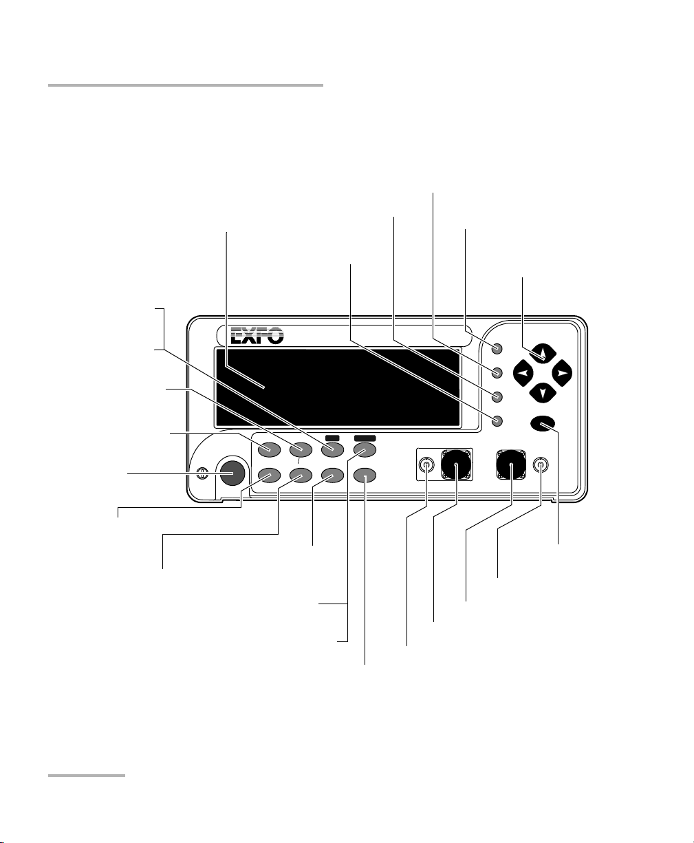
Front Panel
Front Panel
Note: Your PM-1600 may slightly differ from the above illustration.
HIGH-SPEED POWER METER
PM-1600
dB W/W
ENTER
dBm/W Ref
Null
Chan
Range
λ
Avg Shift
Store
Recall
Program
Setup
Analog Out
C1 C2
Ext. Trig
Display
Channel #2 detector port
Relative mode control
see page 16
Power range control
see page 22
Store menu access
see page 41
Confirmation
button
Absolute mode control
see page 14
Average mode control
see page 22
Wavelength control
see page 11
Arrow buttons for
menu navigation and
parameter settings
Recall menu access
see page 42
Program menu access
see page 46
Setup menu access
see page 18
External trigger port
Secondary function control
Channel #1 detector port
Analog output port
On/off button
Display
Channel control (PM-1620)
see page 13
Display mode control
see page 13
Offset nulling control
see page 11
Reference control
see page 16
Introducing the PM-1600 High-Speed Power Meter
2 PM-1600
Front Panel
Front Panel
Note: Your PM-1600 may slightly differ from the above illustration.
HIGH-SPEED POWER METER
PM-1600
dB W/W
ENTER
dBm/W Ref
Null
Chan
Range
λ
Avg Shift
Store
Recall
Program
Setup
Analog Out
C1 C2
Ext. Trig
Display
Channel #2 detector port
Relative mode control
see page 16
Power range control
see page 22
Store menu access
see page 41
Confirmation
button
Absolute mode control
see page 14
Average mode control
see page 22
Wavelength control
see page 11
Arrow buttons for
menu navigation and
parameter settings
Recall menu access
see page 42
Program menu access
see page 46
Setup menu access
see page 18
External trigger port
Secondary function control
Channel #1 detector port
Analog output port
On/off button
Display
Channel control (PM-1620)
see page 13
Display mode control
see page 13
Offset nulling control
see page 11
Reference control
see page 16
Page 13
Introducing the PM-1600 High-Speed Power Meter
High-Speed Power Meter 3
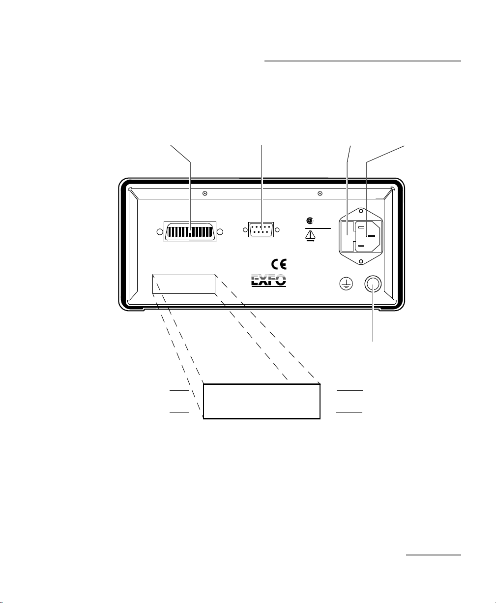
Back Panel
Back Panel
Note: Your PM-1600 may slightly differ from the above illustration.
Ver.
Serial port (RS-232 DTE)
see page 4
Fuse holder
see page 96
Power inlet
see page 8
GPIB port
see page 67
Electro-Optical Engineering
465 Godin Ave.
Vanier, Que., Canada G1M 3G7
R
GPIB IEEE 488.2
SH1, AH1, T6, L4, SR1, RL1, PP0, DC1, DT1, C0, E2
This device complies with part 15 of the FCC rules. Operation is
subject to the following two conditions: (1) this device may not cause
harmful interference and (2) this devic e must accept any interference
received, including interference that may cause undesired operation.
Made in Canada
P/N
S/N
Ver.
Mfg.
date
QST-151E
Serial Port
MODEL: GO
LR107723
100-240 V
50/60 Hz
2 A
F2AL250 V
Ground
PM-1623
12345-AB
A-2.0
November 2001
CUS
P/N
S/N
Mfg.
date
Part number
Serial number
Version number
Manufacturing
Introducing the PM-1600 High-Speed Power Meter
High-Speed Power Meter 3
Back Panel
Back Panel
Note: Your PM-1600 may slightly differ from the above illustration.
Ver.
Serial port (RS-232 DTE)
see page 4
Fuse holder
see page 96
Power inlet
see page 8
GPIB port
see page 67
Electro-Optical Engineering
465 Godin Ave.
Vanier, Que., Canada G1M 3G7
R
GPIB IEEE 488.2
SH1, AH1, T6, L4, SR1, RL1, PP0, DC1, DT1, C0, E2
This device complies with part 15 of the FCC rules. Operation is
subject to the following two conditions: (1) this device may not cause
harmful interference and (2) this devic e must accept any interference
received, including interference that may cause undesired operation.
Made in Canada
P/N
S/N
Ver.
Mfg.
date
QST-151E
Serial Port
MODEL: GO
LR107723
100-240 V
50/60 Hz
2 A
F2AL250 V
Ground
PM-1623
12345-AB
A-2.0
November 2001
CUS
P/N
S/N
Mfg.
date
Part number
Serial number
Version number
Manufacturing
Page 14
Introducing the PM-1600 High-Speed Power Meter
4 PM-1600
RS-232 Connector Pinout
RS-232 Connector Pinout
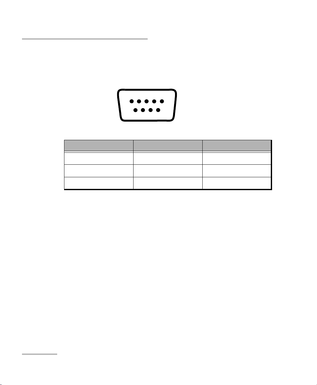
The RS-232 connector (serial port) at the back of the PM-1600 uses a DTE
pinout configuration.
Pin Description Direction
2 Receive (Rx) Input
3 Transmit (Tx) Output
5 Signal ground (Gnd) —
1234 5
6789
Introducing the PM-1600 High-Speed Power Meter
4 PM-1600
RS-232 Connector Pinout
RS-232 Connector Pinout
The RS-232 connector (serial port) at the back of the PM-1600 uses a DTE
pinout configuration.
Pin Description Direction
2 Receive (Rx) Input
3 Transmit (Tx) Output
5 Signal ground (Gnd) —
1234 5
6789
Page 15

High-Speed Power Meter 5
2 Safety Information
Safety Conventions
You should understand the following conventions before using the product
described in this manual:
WARNING
Refers to a potential personal hazard. It requires a
procedure which, if not correctly followed, may result
in bodily harm or injury. Do not proceed beyond a
WARNING unless you understand and meet the
required conditions.
CAUTION
Refers to a potential product hazard. It requires a
procedure which, if not correctly followed, may result
in component damage. Do not proceed beyond a
CAUTION unless you understand and meet the
required conditions.
IMPORTANT
Refers to any information regarding the operation of
the product which you should not overlook.
Page 16

Safety Information
6 PM-1600
General Safety Information
General Safety Information
The following safety precautions must be observed during the operation
and servicing of the units. Failure to comply with these precautions or with
specific indications elsewhere in this manual violates safety standards of
intended use of the unit. EXFO assumes no liability for the user's failure to
comply with these requirements.
➤ This unit is intended for indoor use only.
➤ Unit covers cannot be removed during operation.
➤ The unit must be positioned in a way not to block the ventilation holes
located on each side of the unit.
➤ Installation of replacement parts or modification of the unit should be
carried out by authorized personnel only.
Laser Safety Information
WARNING
Use of controls or adjustments or performance of procedures other
than those specified herein may result in hazardous radiation
exposure.
WARNING
Do not install or terminate fibers while a laser source is active.
Never look directly into a live fiber and ensure that your eyes are
protected at all times.
Page 17

Safety Information
High-Speed Power Meter 7
Electrical Safety Information
Electrical Safety Information
➤ Before powering on the unit, all grounding terminals, extension cords,
and devices connected to it should be connected to a protective
ground via a ground socket. Any interruption of the protective
grounding is a potential shock hazard and may cause personal injury.
➤ Whenever the ground protection is impaired, the unit is not to be used
and must be secured against any accidental or unintended operation.
➤ Only fuses with the required rated current and specified type
(IEC, 250 V, 2 A, fast blow,5 mm x 20 mm (0.197 in x 0.787 in)) may be
used for replacement. Do not use repaired fuses or short-circuited fuse
holders.
➤ Any adjustments, maintenance, and repair of opened units under
voltage should be avoided and carried out only by skilled personnel
aware of the hazards involved. Do not attempt internal service or
adjustment unless another person qualified in first aid is present. Do
not replace any components while power cable is connected.
➤ Operation of any electrical instrument around flammable gases or
fumes constitutes a major safety hazard.
➤ Capacitors inside the unit may be charged even if the unit has been
disconnected from its electrical supply.
AC Requirements
The PM-1600 can operate from any single-phase AC power source between
100 V and 240 V (50 Hz/60 Hz). The maximum input current is 2 A.
Page 18

Safety Information
8 PM-1600
Electrical Safety Information
Power Cable
The PM-1600’s power cable is its disconnecting device.
The PM-1600 uses an international safety standard three-wire power cable.
This cable serves as a ground when connected to an appropriate AC power
receptacle. The type of power cable supplied with each unit is determined
according to the country of destination.
Only qualified electricians should connect a new plug if needed. The color
coding used in the electric cable depends on the cable. New plugs should
meet the local safety requirements and include the following features:
➤ adequate load-carrying capacity
➤ ground connection
➤ cable clamp
➤ If the unit is to be powered via an auto-transformer for voltage
reduction, the common terminal must be connected to the grounded
power source pole.
➤ Insert the plug into a power outlet with a protective ground contact. Do
not use an extension cord without a protective conductor.
➤ Before powering on the unit, the protective ground terminal of the unit
must be connected to a protective conductor using the unit power
cord.
➤ Do not tamper with the protective ground terminal.
WARNING
To avoid electrical shock, do not operate the unit if there are signs
of damage to any part of the outer surface (covers, panels, etc.).
To avoid serious injury, the following precautions must be observed
before powering on the unit.
Page 19

High-Speed Power Meter 9
3 Getting Started with Your
High-Speed Power Meter
Turning the PM-1600 On and Off
To turn the unit on or off, use the red button in the lower left corner of the
front panel.
When you turn on the unit, it beeps twice and performs a self-test, while
displaying startup information as well as the software version number.
Before taking any measurements, it is recommended that you null the
detector offsets (see Nulling Electrical Offsets on page 11).
When the unit is turned off, the following items remain in non-volatile
memory:
➤ manually stored data
➤ reference values
➤ remote-control settings
➤ shortlisted wavelengths
➤ customized settings
➤ saved configurations (up to three setup configurations and up to three
program configurations)
Note: To ensure the power is completely turned off, disconnect the power cord.
IMPORTANT
Before turning the PM-1600 on, please read the Safety Information
on page 5.
Page 20
Getting Started with Your High-Speed Power Meter
10 PM-1600
Selecting a Menu or a Menu Option
Selecting a Menu or a Menu Option
The PM-1600 is equipped with a new type of multifunctional, graphical
liquid crystal display (LCD) with increased brightness, readability, and
resolution that significantly improves both menu navigation and power
meter operation versatility.
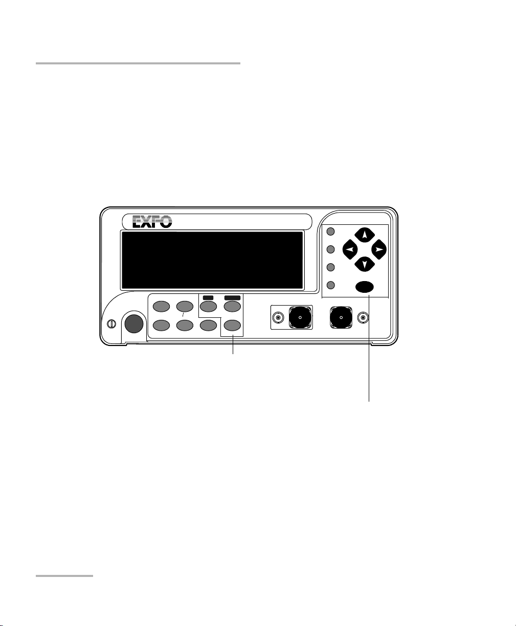
For basic PM-1600 operation, simply press the control buttons at the bottom
of the display.
HIGH-SPEED POWER METER
PM-1600
dB W/W
ENTER
dBm/W Ref
Null
Chan
Range
λ
Avg Shift
Store
Recall
Program
Setup
Analog Out
C1 C2
Ext. Trig
Display
To access a secondary function, press Shift (SH
marker appears in the lower right corner of the
display), then press the desired control button.
To select a menu, press the matching menu
button. For more information, see Storing and
Recalling Power Measurements on page 41 and
Customizing the PM-1600 Display on page 83.
To select a menu option, use the up/down or
left/right arrow keys until the desired option is
highlighted, then confirm by pressing ENTER.
To exit a menu, use the up/down or left/right
arrow keys until Exit is highlighted, then press
ENTER. You c a n al so press the button that gave
access to the menu.
Getting Started with Your High-Speed Power Meter
10 PM-1600
Selecting a Menu or a Menu Option
Selecting a Menu or a Menu Option
The PM-1600 is equipped with a new type of multifunctional, graphical
liquid crystal display (LCD) with increased brightness, readability, and
resolution that significantly improves both menu navigation and power
meter operation versatility.
For basic PM-1600 operation, simply press the control buttons at the bottom
of the display.
HIGH-SPEED POWER METER
PM-1600
dB W/W
ENTER
dBm/W Ref
Null
Chan
Range
λ
Avg Shift
Store
Recall
Program
Setup
Analog Out
C1 C2
Ext. Trig
Display
To access a secondary function, press Shift (SH
marker appears in the lower right corner of the
display), then press the desired control button.
To select a menu, press the matching menu
button. For more information, see Storing and
Recalling Power Measurements on page 41 and
Customizing the PM-1600 Display on page 83.
To select a menu option, use the up/down or
left/right arrow keys until the desired option is
highlighted, then confirm by pressing ENTER.
To exit a menu, use the up/down or left/right
arrow keys until Exit is highlighted, then press
ENTER. You c a n al so press the button that gave
access to the menu.
Page 21
Getting Started with Your High-Speed Power Meter
High-Speed Power Meter 11
Nulling Electrical Offsets
Note: The PM-1600 will beep whenever the unit does not allow an operation.
Note: In this manual, the single-channel power meter is referred to as the
PM-1610 and the dual-channel power meter as the PM-1620.
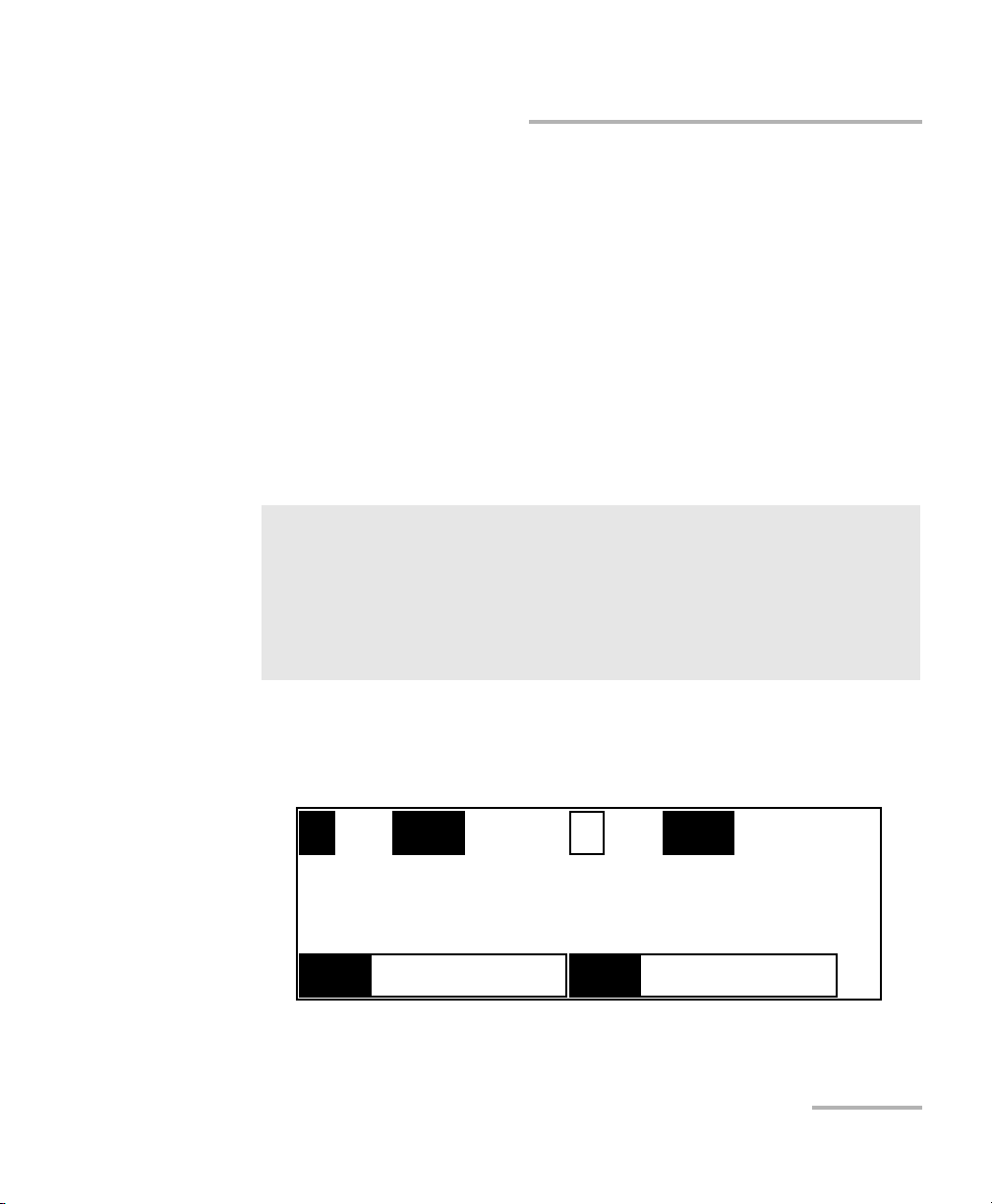
Nulling Electrical Offsets
The Offset Nulling function provides a zero power measurement, thus
eliminating the effects of electronic dark current. For best results and
accuracy, ensure that offsets are nulled before each test session, each time
the unit is turned on, or whenever environmental conditions change while
the power meter is operating (temperature and humidity variations affect
the performance of optical detectors).
To perform a nulling,
1. Place the protective cap over the detector port on which a nulling has
to be performed.
IMPORTANT
Light must not reach the detector when nulling offsets.
When the PM-1600 is turned on after a cold start, allow the unit to
warm up for about 20 minutes (30 minutes for PM-1600W) until the
electronics stabilize and can meet announced optical specifications.
1
AUTO
λ
1310.00 nm
- - - - - - -
dBm
2
LR4 CF
1550.00 nm
1.26
W/W
SH
λ
Getting Started with Your High-Speed Power Meter
High-Speed Power Meter 11
Nulling Electrical Offsets
Note: The PM-1600 will beep whenever the unit does not allow an operation.
Note: In this manual, the single-channel power meter is referred to as the
PM-1610 and the dual-channel power meter as the PM-1620.
Nulling Electrical Offsets
The Offset Nulling function provides a zero power measurement, thus
eliminating the effects of electronic dark current. For best results and
accuracy, ensure that offsets are nulled before each test session, each time
the unit is turned on, or whenever environmental conditions change while
the power meter is operating (temperature and humidity variations affect
the performance of optical detectors).
To perform a nulling,
1. Place the protective cap over the detector port on which a nulling has
to be performed.
IMPORTANT
Light must not reach the detector when nulling offsets.
When the PM-1600 is turned on after a cold start, allow the unit to
warm up for about 20 minutes (30 minutes for PM-1600W) until the
electronics stabilize and can meet announced optical specifications.
1
AUTO
λ
1310.00 nm
- - - - - - -
dBm
2
LR4 CF
1550.00 nm
1.26
W/W
SH
λ
Page 22

Getting Started with Your High-Speed Power Meter
12 PM-1600
Nulling Electrical Offsets
2. If necessary, select the desired channel (in the case of a PM-1620) by
pressing Chan. In the above figure, channel #1 is currently selected.
3. Press Shift, then Null. The offset nulling process takes approximately
10 seconds. Once done, the unit returns to the previously active
operation state.
Note: If you are trying to perform an offset nulling with a protective cap
improperly tightened on the detector port, the message Light detected will
be briefly displayed. If so, ensure the protective cap is properly tightened
and restart the offset nulling.
Note: Offset nulling constants are retained until a new offset nulling is performed.
Page 23
High-Speed Power Meter 13
4 Acquiring Power
Measurements
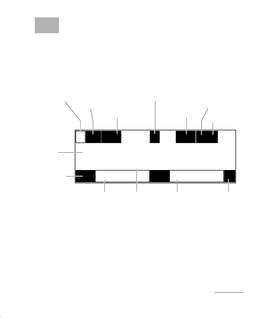
Setting a Display Mode
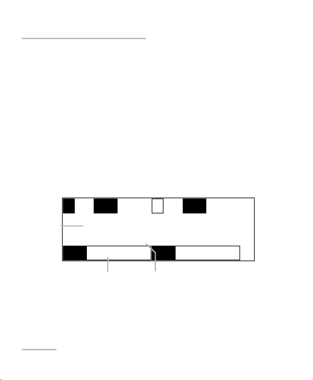
A typical display in power measurement mode might look as follows.
To set the display mode, i.e., the data type at the bottom of the display,
1. If necessary, select the desired channel (PM-1620) by pressing Chan.
The current wavelength is displayed for the active channel. In the
above figure, channel #2 is currently selected.
2. Press Shift, then Display. The current reference value is displayed for
the active channel (in dBm or W units, depending on the currently
selected measurement unit).
AVG1
AUTO
REF
-52.640 dBm
5.585
dB
2
LR4 CF
1310.26 nm
1.26
dB
Sensitivity range
(auto) active
Sensitivity range
(manual) active
Channel 1 display zone
Channel 2 display zone
Inactive channel
Active channel
Averaging
mode
active
Correction factor
active
Power
reading
Reference value
(channel #1)
Current unit
Current wavelength
(channel #2)
Secondary function
indicator
SH
λ
Display mode
tab
O
Offset
indicator
Current unit
High-Speed Power Meter 13
4 Acquiring Power
Measurements
Setting a Display Mode
A typical display in power measurement mode might look as follows.
To set the display mode, i.e., the data type at the bottom of the display,
1. If necessary, select the desired channel (PM-1620) by pressing Chan.
The current wavelength is displayed for the active channel. In the
above figure, channel #2 is currently selected.
2. Press Shift, then Display. The current reference value is displayed for
the active channel (in dBm or W units, depending on the currently
selected measurement unit).
AVG1
AUTO
REF
-52.640 dBm
5.585
dB
2
LR4 CF
1310.26 nm
1.26
dB
Sensitivity range
(auto) active
Sensitivity range
(manual) active
Channel 1 display zone
Channel 2 display zone
Inactive channel
Active channel
Averaging
mode
active
Correction factor
active
Power
reading
Reference value
(channel #1)
Current unit
Current wavelength
(channel #2)
Secondary function
indicator
SH
λ
Display mode
tab
O
Offset
indicator
Current unit
Page 24
Acquiring Power Measurements
14 PM-1600
Measuring Absolute Power
3. Press Shift a second time, then Display. The current correction factor
(CF) is displayed for the active channel (in dB or W/W units,
depending on the currently selected measurement unit).
4. Press Shift again, then Display. The Offset value (O) appears for the
active channel (in dB or W/W units, depending on the currently
selected measurement unit).
Note: On a PM-1610 single-channel power meter, two different data types
simultaneously appear at the bottom of the display. To select the desired
display mode, just press Display.
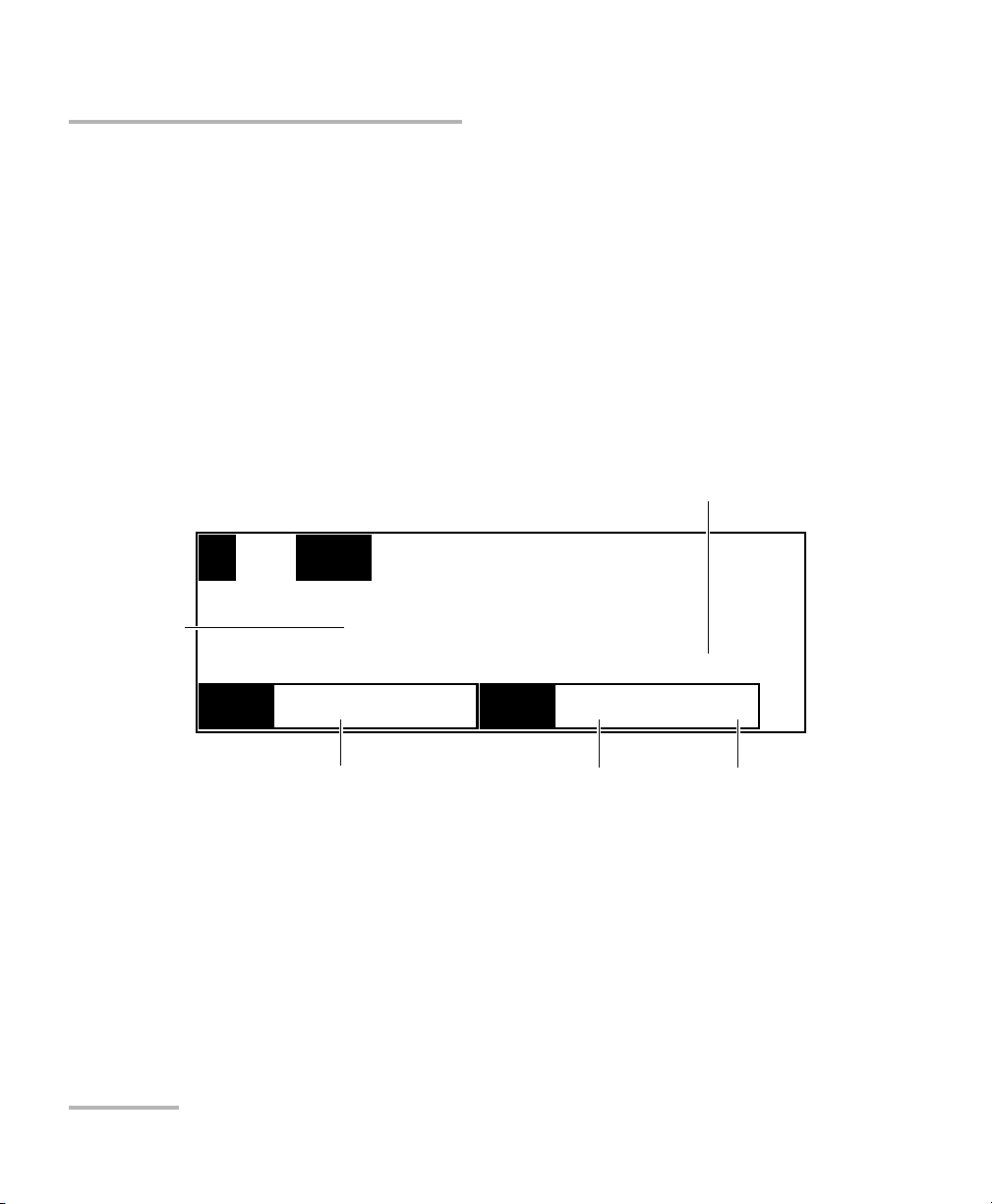
Measuring Absolute Power
When in absolute power, measured values are displayed in either dBm or
W units (pW, nW, µW, mW...) according to the power of the signal, and the
displayed value represents the absolute optical power reaching the
detector within specified uncertainty.
To display absolute power,
1. If necessary, select the desired channel (PM-1620). In the above figure,
channel #1 is currently selected.
1
AUTO
λ
1310.00 nm
-14.278
dBm
2
LR2 CF
1550.00 nm
1.26
W/W
SH
λ
Power reading
Current wavelength Measurement unit
Acquiring Power Measurements
14 PM-1600
Measuring Absolute Power
3. Press Shift a second time, then Display. The current correction factor
(CF) is displayed for the active channel (in dB or W/W units,
depending on the currently selected measurement unit).
4. Press Shift again, then Display. The Offset value (O) appears for the
active channel (in dB or W/W units, depending on the currently
selected measurement unit).
Note: On a PM-1610 single-channel power meter, two different data types
simultaneously appear at the bottom of the display. To select the desired
display mode, just press Display.
Measuring Absolute Power
When in absolute power, measured values are displayed in either dBm or
W units (pW, nW, µW, mW...) according to the power of the signal, and the
displayed value represents the absolute optical power reaching the
detector within specified uncertainty.
To display absolute power,
1. If necessary, select the desired channel (PM-1620). In the above figure,
channel #1 is currently selected.
1
AUTO
λ
1310.00 nm
-14.278
dBm
2
LR2 CF
1550.00 nm
1.26
W/W
SH
λ
Power reading
Current wavelength Measurement unit
Page 25

Acquiring Power Measurements
High-Speed Power Meter 15
Measuring Absolute Power
2. If necessary, press λ to select the appropriate wavelength from the
shortlist (see the section on viewing wavelength list on page 25).
Note: The wavelength may take some time to change on the display due to a low
refresh rate. To set the refresh rate, see Setting Refresh Rate on page 34.
3. Press dBm/W to display the absolute power of the signal received at
the detector port. The dBm/W button is also used to toggle between
dBm and W measurement units.
An absolute power measurement in negative W units indicates that
electrical offsets were improperly nulled. If so, repeat the offset nulling
(see Nulling Electrical Offsets on page 11).
Note: When ------- is displayed, the power level detected is below the lower
limit of the selected measurement range. When +++++++ is
displayed, the power level detected is above the upper limit of the selected
measurement range. See Setting Measurement Range on page 22.
When !!!!!!! is displayed, the displayed data is in transition (range was
changed in power measurement mode, with Autorange selected).
When *******is displayed, a programmed acquisition is running with
a high sampling rate.
Page 26
Acquiring Power Measurements
16 PM-1600
Measuring Relative Power
Measuring Relative Power
Power measurements can be displayed as a deviation from an absolute
reference value. The relative power is particularly useful when performing
insertion loss measurements.
Relative power is displayed in dB when the reference value is measured in
dBm. If this is the case, the value will either be positive or negative since
the actual measured power is higher or lower than the reference power.
If the reference value is in W, the relative power will be displayed in W/W
units. The relative power will then represent the deviation ratio from the
reference.
In the example on the previous page, the measured power is 30.112 dB
higher than the reference value of −32.218 dBm. The absolute power is
−2.106 dBm.
To display relative power,
1. If necessary, select the desired channel (PM-1620).
2. If necessary, press
λ to select the appropriate wavelength from the
shortlist (see the section on viewing wavelength list on page 25).
1
AUTO
λ
1310.25 nm
30.112
CF
-32.218 dBm
dB
SH
Relative power
Current wavelength
Reference value
REF
Relative power unit
Reference unit
Page 27

Acquiring Power Measurements
High-Speed Power Meter 17
Measuring Relative Power
3. Press dB/W/W until the display switches to relative mode in dB (where
the value displayed is equal to the absolute power minus the
previously stored reference power) or in W/W (where the value
displayed is the deviation ratio from the reference). Pressing dB/W
/W
again switches between dB and W/W measurement units for the
relative power and reference value.
When you access relative mode, the PM-1600 displays the last reference
value entered at the current wavelength (to view the reference value, set
the appropriate channel to reference display mode).
However, to display meaningful relative power readings, it is important to
have an appropriate reference value, using appropriate adapters and test
jumpers, and connecting the optical circuit being referenced to a detector
port.
Note: If you set a reference while a correction factor (CF) is active, the reference
measurement will take the correction factor into account.
To set a reference value, two choices are available.
Entering the Current Power as the Reference Value
To enter the current power,
1. If necessary, select the desired channel (PM-1620).
2. If necessary, press
λ to select the appropriate wavelength.
3. Press dBm/W to select the desired measurement unit.
4. Press Ref to use the current power value as the new reference.
Note: Pressing Ref switches the display to relative mode.
Page 28
Acquiring Power Measurements
18 PM-1600
Measuring Relative Power
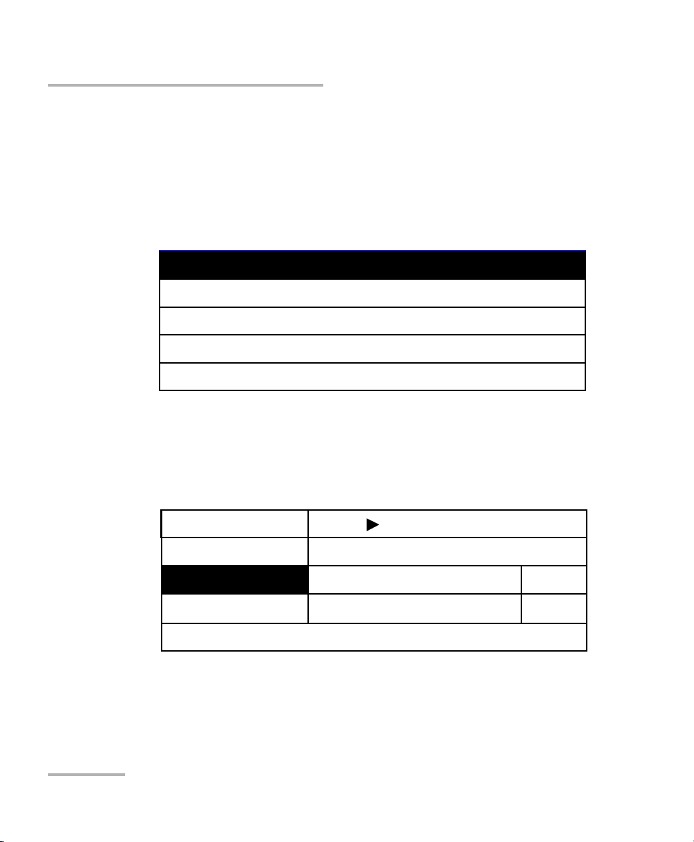
Entering a Specific Reference Value
To enter a specific value,
1. If necessary, press
λ to select the appropriate wavelength.
2. Press dBm/W to select the desired measurement unit.
3. Press Setup to access the Setup menu.
4. Use the up/down arrow keys to select Channel 1 Setup or Channel 2
Setup, then press ENTER. The current channel settings are displayed.
5. Use the up/down arrow keys to select Reference.
5a. To clear the current reference, use the left/right arrow keys to
select Reset, then confirm by pressing ENTER.
System Setup
Wavelength List & Corr. Factor
Channel 1 Setup
Channel 2 Setup
Exit
Resolution
Averaging
Reference
002
−
68.975 dBm
3.0103 dB
(Active)
Reset
4
Exit Channel 1 Setup
Offset
100.000 dB
Reset
Acquiring Power Measurements
18 PM-1600
Measuring Relative Power
Entering a Specific Reference Value
To enter a specific value,
1. If necessary, press
λ to select the appropriate wavelength.
2. Press dBm/W to select the desired measurement unit.
3. Press Setup to access the Setup menu.
4. Use the up/down arrow keys to select Channel 1 Setup or Channel 2
Setup, then press ENTER. The current channel settings are displayed.
5. Use the up/down arrow keys to select Reference.
5a. To clear the current reference, use the left/right arrow keys to
select Reset, then confirm by pressing ENTER.
System Setup
Wavelength List & Corr. Factor
Channel 1 Setup
Channel 2 Setup
Exit
Resolution
Averaging
Reference
002
−
68.975 dBm
3.0103 dB
(Active)
Reset
4
Exit Channel 1 Setup
Offset
100.000 dB
Reset
Page 29

Acquiring Power Measurements
High-Speed Power Meter 19
Measuring Corrected Power
5b. To modify the current reference, press ENTER to select the
reference edit box, then use the left/right arrow keys to select the
desired sign and digit, and the up/down arrow keys to increase or
decrease the flashing value. Confirm by pressing ENTER. You can
enter a reference value from −90.000 dBm to +90.000 dBm or
from +001.0000 pW to +999.9999 kW.
Note: You can toggle between dBm and W units while in the Channel Setup
menu by pressing dBm/W.
6. Exit the Channel Setup menu and then the Setup menu.
Measuring Corrected Power
A correction factor (CF) can be applied to any measurement that is
displayed in either dB, dBm, W, or W/W units.
When expressed in dB, the correction factor, which can be positive or
negative, is applied to the measured power. When expressed in W/W, the
correction factor is a deviation from the measured power. This feature
provides additional flexibility and can be useful when compensating for
known inaccuracies (power gains or losses) at specific wavelengths.
To use the corrected power display, see Setting a Correction Factor on
page 30. When a correction factor is active, i.e., different from 0.000 dB or
1.0000 W/W, the CF marker appears at the top of the display for the
matching channel.
Note: Special care must be taken when setting a correction factor as it emulates a
new calibration (the PM-1600's calibration is not affected and will be
restored by setting the CF back to a null value).
Page 30

Acquiring Power Measurements
20 PM-1600
Measuring Corrected Power
Setting an Offset Value
You can use the Offset function to take into account, in the power
displayed, of a known gain or loss in the link that is not already included in
the signal reaching the detector. Contrary to the correction factor, which
applies to a specific wavelength, the offset value applies to any wavelength
when it is enabled on a specific channel.
To enter an offset value,
1. If necessary, press
λ to select the appropriate wavelength.
2. Press dBm/W to select the desired measurement unit.
3. Press Setup to access the Setup menu.
4. Use the up/down arrow keys to select Channel 1 Setup or Channel 2
Setup, then press ENTER. The current channel settings are displayed.
System Setup
Wavelength List & Corr. Factor
Channel 1 Setup
Channel 2 Setup
Exit
Page 31
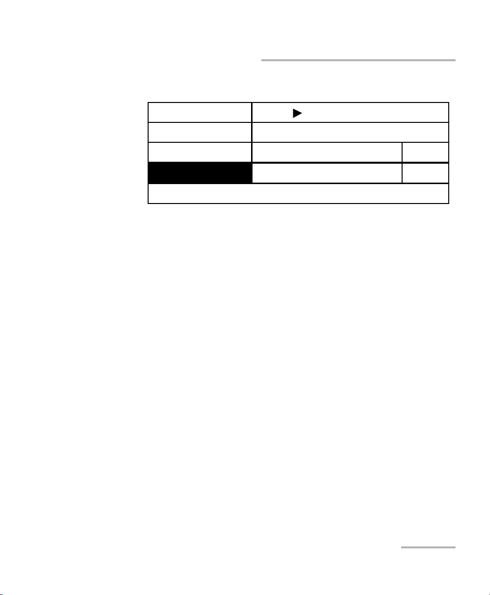
Acquiring Power Measurements
High-Speed Power Meter 21
Measuring Corrected Power
5. Use the up/down arrow keys to select Offset.
5a. To clear the current offset, use the left/right arrow keys to select
Reset, then confirm by pressing ENTER.
5b. To modify the current offset, press ENTER to select the offset edit
box, then use the left/right arrow keys to select the desired sign
and digit, and the up/down arrow keys to increase or decrease
the flashing value. Confirm by pressing ENTER. You can enter an
offset value from −90.000 dBm to +90.000 dBm or from
+001.0000 pW to +999.9999 kW.
Note: The Offset value will be displayed in dB or W/W units, depending on the
currently selected measurement unit.
Note: You can toggle between dBm and W units while in the Channel Setup
menu by pressing dBm/W.
6. Exit the Channel Setup menu and then the Setup menu.
Resolution
Averaging
Reference
002
−
68.975 dBm
3.0103 dB
(Active)
Reset
4
Exit Channel 1 Setup
Offset
−
100.000 dB
Reset
Page 32

Acquiring Power Measurements
22 PM-1600
Displaying Averaged Measurement
Displaying Averaged Measurement
To display averaged power measurement,
1. If necessary, select the desired channel (PM-1620).
2. Press Avg.
When averaging is enabled, the AVG marker appears at the top of the
display for the matching channel. The most recent measurement samples,
of which the number is set in the System Setup menu (see Choosing a
Number of Measurements for Averaging on page 36), are then used to
compute an unweighted average.
Setting Measurement Range
The measurement range (or gain scale) applied to the power
measurement detector can be manually selected to prevent the automatic
scale adjustment performed by the instrument. A manual adjustment of
the dynamic gain scale will lock the measurement range to a specific level.
The measurement range should be locked when the analog output (see
Using the Analog Output on page 65) is used to avoid variations in voltage
output due to scale changes. It is also necessary to use a manual range to
achieve high-rate, programmed acquisitions (see Programming Data
Acquisitions on page 45).
Two types of manual ranges are available:
➤ The Low range provides a lower dynamic range (typically 22 dB) per
scale with better signal-to-noise ratio and resolution.
➤ The High range provides a higher dynamic range (typically 42 dB) per
scale with an inferior signal-to-noise ratio. In the PM-1620 model, each
channel is adjusted independently.
Page 33

Acquiring Power Measurements
High-Speed Power Meter 23
Setting Measurement Range
To set the measurement range,
1. If necessary, select the desired channel (PM-1620).
2. Press Range until the required measurement range marker is shown at
the top of the display for the matching channel. The table shown below
displays the permitted manual ranges when the currently selected
measurement unit is dB or dBm. The power range values displayed are
typical at 1310 nm.
Note: Select a manual range in power measurement mode when the input signal
has unstable or modulated variations. This prevents !!!!!!! from being
displayed upon constantly changing gain scales.
Low Range (LR) High Range (HR)
−3.90 to 18.30 dBm (LR1)
a
a. InGaAs detector has a +9 dBm saturation limit.
−29.60 to 18.30 dBm (HR1)
a
−12.50 to 9.90 dBm (LR2)
a
−38.20 to 9.90 dBm (HR2)
a
−32.49 to −10.09 dBm (LR3) −58.29 to −10.09 dBm (HR3)
−52.27 to −29.87 dBm (LR4) −78.00 to −29.87 dBm (HR4)
−72.01 to −49.61 dBm (LR5) —
−90.00 to −69.61 dBm (LR6) —
Page 34

Acquiring Power Measurements
24 PM-1600
Viewing Statistics
Viewing Statistics
Although it is not possible to retrieve acquisition results from the PM-1600
except when using remote control, this function provides you with
statistical information on the last acquisition performed.
To view sta t i s t i c s ,
1. Press Program to access the Program menu.
2. Use the up/down or left/right arrow keys to select Statistics.
3. Confirm by pressing ENTER. The last statistics available are displayed.
Note: Reject indicates the percentage of values rejected during measurements.
When !!!!!!! is displayed, the displayed data is in transition. When
------- is displayed, the power level detected is below the lower limit of
the selected measurement range. When +++ ++++ is displayed, the
power level detected is above the upper limit of the selected measurement
range.
Min.
Max.
Mean
Stdev.
Reject
−
37.2360 dBm
−
6.3334 dBm
−
9.290 dBm
−
10.649 dB
99.445 n W /W
189.98 n W /W
136.50 n W /W
27.380 n W /W
Exit
10.00 % 0.00 %
Page 35

Acquiring Power Measurements
High-Speed Power Meter 25
Managing the Wavelength List
Managing the Wavelength List
To view the list,
1. Press Setup to access the Setup menu.
2. Use the up/down arrow keys to select Wavel eng th List & Cor r. Facto r,
then press ENTER. The number of wavelengths in the list is displayed. If
the maximum number of wavelengths (32) in the list is reached, full is
displayed. If the list is empty, empty is displayed. A
mark is displayed
next to the active wavelength to indicate that it is on the wavelength
list.
System Setup
Wavelength List & Corr. Factor
Channel 1 Setup
Channel 2 Setup
Exit
Sampling
λ
CF Ch1
CF Ch2
Exit
View
λ
List (31 λ)
1537.98 nm
1.0000 W/W
Sort
λ
Add
λ
Clear CF
Clear CF
Del All
Del
λ
+0.000 dB
Active
wavelength
Page 36

Acquiring Power Measurements
26 PM-1600
Managing the Wavelength List
3. Press ENTER. The wavelength list is displayed with the correction
factor (CF) set for each wavelength on the list (for both channels in a
PM-1620).
Note: By default, the six most commonly used wavelengths (850 nm, 980 nm,
1310 nm, 1480 nm, 1550 nm, and 1625 nm)are saved in the wavelength
shortlist.
Note: The correction factor is displayed in W/W or dB depending on the currently
selected measurement unit.
4. Use the up/down arrow keys to scroll through the wavelength list.
5. To exit the wavelength list, press ENTER.
Note: A wavelength list can be set for each different setup configuration (up to
three setup configurations are possible). To save or recall a setup
configuration, see Saving a Setup Configuration on page 37, or Recalling a
Setup Configuration on page 38.
λ
#
λ
(nm)
CF Ch1 (W/W)
CF Ch2 (dB)
1850.00
+1.0020
+0.000
2980.00
+1.0000
-0.100
3
1310.00
+1.0000
+0.000
4
1480.00
+1.0000
+0.000
5 1550.00
+1.0000
+0.000
6 1550.25
+1.0000
+0.000
Page 37

Acquiring Power Measurements
High-Speed Power Meter 27
Managing the Wavelength List
To sort the list by wavelengths,
1. Press Setup to access the Setup menu.
2. Use the up/down arrow keys to select Waveleng th L ist & Cor r. Facto r.
3. Press ENTER.
4. Use the left/right arrow keys to select Sort
λ .
5. Confirm by pressing ENTER. The wavelengths are sorted in ascending
order.
Note: If the list of wavelengths is full, delete a wavelength before adding a new
one. See section on deleting a wavelength on page 29.
To add a wavelength to the list,
1. Press Setup to access the Setup menu.
2. Use the up/down arrow keys to select Waveleng th L ist & Cor r. Facto r.
3. Press ENTER.
4. Use the up/down arrow keys to select
λ .
5. With
λ highlighted, use the left/right arrow keys to select Add λ, then
confirm by pressing ENTER. The current wavelength is displayed in the
wavelength edit box.
6. Use the left/right arrow keys to select the flashing digit of the
wavelength and the up/down keys to increase or decrease the flashing
digit. You can enter a value with a 0.01 nm resolution.
7. Confirm the new wavelength by pressing ENTER.
Note: Adding a wavelength to the list will not affect the current wavelength in
measurement mode.
Page 38

Acquiring Power Measurements
28 PM-1600
Managing the Wavelength List
To modify a wavelength,
1. Follow steps 1 to 4 in section on viewing the wavelength list on
page 25. Select the wavelength to be modified by pressing ENTER.
2. Use the up/down arrow keys to select
λ .
3. Press ENTER.
4. Use the left/right arrow keys to select the flashing digit of the
wavelength and the up/down keys to increase or decrease the flashing
digit. You can enter a value with a 0.01 nm resolution.
Note: The
mark in the wavelength edit box indicates that the wavelength is on
the wavelength list. This mark may disappear as you modify the value in
the wavelength edit box.
5. Confirm by pressing ENTER.
Page 39

Acquiring Power Measurements
High-Speed Power Meter 29
Managing the Wavelength List
To delete a specific wavelength from the list,
1. Follow steps 1 to 4 in section on viewing the wavelength list on
page 25. Select the wavelength to be deleted by pressing ENTER.
Note: You can also select the wavelength while in the Wavelength List & Corr.
Factor menu by pressing
λ .
2. With the wavelength to be deleted displayed in the wavelength edit
box, use the up/down arrow keys to select
λ .
3. Use the left/right arrow keys to select Del
λ .
4. Confirm the wavelength deletion by pressing ENTER.
To remove all the wavelengths from the list,
1. Press Setup to access the Setup menu.
2. Use the up/down arrow keys to select Waveleng th L ist & Cor r. Facto r.
3. Press ENTER.
4. Use the left/right arrow keys to select Del All.
5. Confirm the wavelength list deletion by pressing ENTER.
Page 40

Acquiring Power Measurements
30 PM-1600
Setting a Correction Factor
Setting a Correction Factor
Applying a correction factor to the measured power is useful when
compensating for known inaccuracies (power gains or losses).
When a dB correction factor other than +0.000 is defined, the displayed
power is equal to the actual power plus the value of the correction factor.
When a W/W correction factor other than 1.0000 is defined, the displayed
power is equal to the actual power times the value of the correction factor.
With an active correction factor, the CF marker appears at the top of the
display for the matching channel.
Note: Setting a correction factor emulates a new calibration (the PM-1600's
calibration is not affected and will be restored by setting back the CF to a
null value).
When expressed in dB, the correction factor can be a positive or negative
value. When the currently selected measurement unit is W, the correction
factor is expressed in W/W, indicating a multiplication factor for the current
wavelength and channel. The correction factor expressed in W/W will
always be a positive value.
To select a correction factor,
1. Press
λ to select the appropriate wavelength, then Setup to access the
Setup menu, then use the up/down arrow keys to select Wavelength
List & Corr. Factor, and press ENTER.
Or
Follow steps 1 to 4 in section on viewing the wavelength list on
page 25. Select the wavelength by pressing ENTER.
Note: You can also select the wavelength while in the Wavelength List & Corr.
Factor menu by pressing
λ .
2. Use the up/down arrow keys to select CF Ch 1 or CF Ch 2 (PM-1620).
The current correction factor for the matching wavelength is displayed
in dB or W/W, depending on the currently selected measurement unit.
Page 41
Acquiring Power Measurements
High-Speed Power Meter 31
Setting a Correction Factor
Note: You can toggle between dB and W/W units while in the Wa vel ength List &
Corr. Factor menu by pressing dB/W
/W.
3. Press ENTER.
4. Use the left/right arrow keys to select the flashing digit of the correction
factor and the up/down keys to increase or decrease the flashing digit.
You can enter a value from −5.999 dB to +6.000 dB or from 0.2512 W/W
to 3.9811 W/W.
5. Confirm the correction factor by pressing ENTER. The newly defined
correction factor will be automatically applied when you return to
measurement mode, with the CF marker at the top of the display for
the matching channel.
Note: Although the wavelength list applies to all channels, the correction factor
applies to the specific wavelength and channel at which it was set.
View λ List (26 λ)
λ
CF Ch1
CF Ch2
Exit
1310.00 nm
1.2000 W/W
Sort
λ
Add
λ
Clear CF
Clear CF
Del All
Del
λ
+0.000 dB
Page 42

Acquiring Power Measurements
32 PM-1600
Setting Display Resolution
To delete a correction factor,
1. Press
λ to select the appropriate wavelength, then Setup to access the
Setup menu, then use the up/down arrow keys to select Wavelength
List & Corr. Factor, and press ENTER.
Or
Follow steps 1 to 4 in section on viewing the wavelength list on
page 25. Select the wavelength by pressing ENTER.
Note: You can also select the wavelength while in the Wavelength List & Corr.
Factor menu by pressing
λ .
2. Use the up/down arrow keys to select CF Ch 1 or CF Ch 2 (PM-1620).
The current correction factor for the matching wavelength is displayed
in dB or W/W, depending on the currently selected measurement unit.
Note: You can toggle between dB and W/W units while in the Wav ele ngt h List &
Corr. Factor menu by pressing dB/W
/W.
3. Use the left/right arrow keys to select Clear CF.
4. Confirm the deletion by pressing ENTER. The correction factor is
immediately reset to +0.000 dB or 1.0000 W/W and, therefore,
deactivated.
Setting Display Resolution
Depending on the required resolution and operating power level 0, 1, 2, 3,
or 4 digits can be displayed after the decimal point. When AUTO is
selected, the display resolution is determined by the power level being
measured.
Note: The AUTO marker on the display in measurement mode does not refer to
the automatic display resolution but to the measuring range (see Setting
Measurement Range on page 22).
Page 43

Acquiring Power Measurements
High-Speed Power Meter 33
Setting Display Resolution
To set the display resolution of a power measurement expressed
in dB or dBm,
1. Press Setup to access the Setup menu.
2. Use the up/down arrow keys to select Channel 1 Setup or Channel 2
Setup (PM-1620), then press ENTER. The current resolution is
displayed with the current power measurement in real time.
3. Press ENTER to access the display resolution edit box.
4. Use the up/down arrow keys to change the display resolution. The
power measurement is immediately affected as can be seen in the
display resolution edit box.
5. Press ENTER to confirm the new display resolution.
Note: You can toggle between dBm and W units while in the Channel Setup
menu by pressing dBm/W.
Note: When W is selected, the display resolution changes to AUTO (different W
units will be used according to the power of the signal detected). It is then
impossible to access the display resolution edit box.
Resolution
Averaging
Reference
Offset
002 (Inactive)
−
68.975 dBm
−
26.1746 dBm
4
Current display
resolution
Current power measurement
and unit
Exit Channel 2 Setup
100.000 dB
Reset
Reset
Page 44

Acquiring Power Measurements
34 PM-1600
Setting Refresh Rate
Setting Refresh Rate
This function allows you to define the refresh rate of the power readings in
power measurement mode (for both channels in a PM-1620 dual-channel
power meter).
To set the refresh rate,
1. Press Setup to access the Setup menu.
2. Press ENTER to access the System Setup menu.
3. Use the up/down arrow keys to select Refresh Rate. The current
refresh rate is displayed.
4. Press ENTER to access the refresh rate edit box.
5. Use the up/down arrow keys to set the refresh rate between 1/2 Hz,
1Hz, 2Hz, 4Hz, 8Hz, and 16Hz.
6. Press ENTER to confirm the new refresh rate.
Exit
Sampling Rte
Refresh Rate
Backlight
Contrast
Video Mode
256Hz
16Hz
ON
STD
RS232 / GPIB
GPIB Addr.
Save
Recall
GPIB
15
# 3
# 3
Page 45

Acquiring Power Measurements
High-Speed Power Meter 35
Setting Sampling Rate
Setting Sampling Rate
This function allows you to define the number of power readings per
second in power measurement mode (for both channels in a PM-1620
dual-channel power meter) with a maximum of 256 per second.
In power measurement mode, power measurements are constantly
updated on the measurement display. Samples can also be retrieved with
the GPIB or RS-232 interface (refer to the IQ-200 GPIB and Application
Development Guide).
According to your specific requirements and the power level, you will
select a sampling rate that will optimize instrument flexibility and
measurement stability as well as determine the quantity of data generated
during data acquisition.
Note: Use a lower sampling rate with averaging active (see Displaying Averaged
Measurement on page 22) for greater repeatability when measuring very
low power.
To set the sampling rate,
1. Press Setup to access the Setup menu.
2. Press ENTER to access the System Setup menu. The current sampling
rate is displayed.
3. Press ENTER to access the sampling rate edit box.
4. Use the up/down arrow keys to select the rate from the 11 values listed.
Values vary from 1/4 Hz to 256 Hz.
5. Press ENTER to confirm the new sampling rate. If using a PM-1620
dual-channel power meter, the sampling rate applies to both channels.
Note: The sampling rate defined in the Setup menu is independent of the
sampling rate defined in the Program menu.
Page 46

Acquiring Power Measurements
36 PM-1600
Choosing a Number of Measurements for Averaging
Choosing a Number of Measurements for
Averaging
Power measurements can be averaged over a programmable number of
samples by pressing Avg in power measurement mode. Measurements will
continue to be displayed at the specified sampling and refresh rates (see
Setting Sampling Rate on page 35 and Setting Refresh Rate on page 34),
but the average will include the specified number of power samples.
To set the number of measurements for averaging,
1. Press Setup to access the Setup menu.
2. Use the up/down arrow keys to select Channel 1 Setup or Channel 2
Setup (PM-1620), then press ENTER.
3. Use the up/down arrow keys to select Averaging. The current
averaging number is displayed with the averaging status (Active or
Inactive).
4. Press ENTER to access the averaging number edit box.
5. Use the left/right arrow keys to select the flashing digit of the averaging
number and the up/down keys to increase or decrease the flashing
digit. You can enter a value from 002 to 999.
6. Press ENTER to confirm the new number of measurements for
averaging.
Note: You can activate or deactivate the averaging function while in the Channel
Setup menu by pressing Avg.
Page 47

Acquiring Power Measurements
High-Speed Power Meter 37
Saving a Setup Configuration
Saving a Setup Configuration
Once the PM-1600 has been customized for a specific application or user, it
is possible to save the configuration of the parameters that have been set in
the Setup menu, with the exception of the contrast setting. Up to three
setup configurations can be saved and recalled. The following parameters
are saved:
➤ channel parameters (measurement unit, display resolution, averaging
status and number, measuring range, reference value, active
wavelength, correction factor, and display mode)
➤ system parameters (sampling rate, refresh rate, backlight, video mode,
RS-232/GPIB address, wavelength shortlist, active channel, and active
program)
To save a setup configuration,
1. Press Setup to access the Setup menu.
2. Press ENTER to access the System Setup menu.
3. Use the up/down or left/right arrow keys to select Save. The current
setup configuration number is displayed.
Note: (Mod.) indicates that a recalled setup configuration has been modified.
4. Press ENTER to access the setup configuration number edit box.
5. Use the up/down arrow keys to set a setup configuration number from
1 to 3.
6. Confirm the new setup configuration by pressing ENTER. It takes a few
seconds to save a setup configuration.
Page 48

Acquiring Power Measurements
38 PM-1600
Recalling a Setup Configuration
Recalling a Setup Configuration
Once you have saved a setup configuration, you can recall it at any time.
To recall a configuration,
1. Press Setup to access the Setup menu.
2. Press ENTER to access the System Setup menu.
3. Use the up/down or left/right arrow keys to select Recall. The current
setup configuration number is displayed.
4. Press ENTER to access the setup configuration number edit box.
5. Use the up/down arrow keys to select the required configuration
number.
6. Confirm by pressing ENTER. It takes a few seconds to recall a setup
configuration.
Page 49

Acquiring Power Measurements
High-Speed Power Meter 39
Resetting the PM-1600
Resetting the PM-1600
When turning on the unit, press ENTER until the unit beeps repeatedly. All
the user-defined parameters are reset to their default values. These are
displayed in the following tables.
Channel Parameters
Measurement unit W
Display resolution AUTO
Averaging Active
Number of measurements
used for averaging
2
Measuring range Autorange
Reference Null
Offset Null
Wavelength 850 nm
Correction factor OFF
Display mode Reference
Page 50

Page 51

High-Speed Power Meter 41
5 Storing and Recalling Power
Measurements
Storing Power Measurements Manually
The PM-1600 has 100 memory registers to manually store absolute or
relative power measurements (for both channels in a PM-1620).
To store a measurement manually, select the desired measurement and
then press Store. The register number is briefly displayed.
Note: The register number automatically increases each time you store a
measurement.
When the maximum number of 100 power measurements is reached, it is
no longer possible to store new power measurements. Full is then
displayed.
Note: You may observe a difference between the power measurement displayed
and the power measurement stored, especially if the sampling rate is
significantly higher than the refresh rate.
1
AUTO
λ
1310.00 nm
-14.278
dBm
2
LR4 CF
1550.00 nm
1.26
W/W
SH
λ
Register number
M26
Page 52

Storing and Recalling Power Measurements
42 PM-1600
Recalling Manually Stored Power Measurements
Recalling Manually Stored Power
Measurements
The power measurements that you stored manually (see Storing Power
Measurements Manually on page 41) can be recalled one register at a time.
To retrieve a manually stored power measurement,
1. Press Recall. The display either indicates the number of stored power
measurements or a message stating whether the memory is empty or
full.
2. Press ENTER. A stored power measurement is displayed with the
matching register number.
3. Use the up/down arrow keys to select the required register.
Note: You can keep the up/down arrow keys pressed to quickly scan the power
measurements in adjacent registers. To speed up the scan, use the left/right
arrow keys.
4. To exit t h e Recall menu, press Recall, or select Exit then press Enter.
When recalling a stored power measurement, it is possible to change the
display mode (on both channels when using a PM-1620) and the
measurement unit.
View Stored Data (27 values)
Erase Stored Data
Exit
Page 53

Storing and Recalling Power Measurements
High-Speed Power Meter 43
Erasing Manually Stored Power Measurements
Erasing Manually Stored Power Measurements
The manually stored power measurements (up to 100) can be erased as a
batch.
To erase a stored power measurement,
1. Press Recall.
2. Use the up/down arrow keys to select Erase Stored Data.
3. Press ENTER to confirm the deletion. It takes a few seconds to erase all
stored power measurements.
4. To exit t h e Recall menu, press Recall, or select Exit then press Enter.
IMPORTANT
After you press ENTER, all the manually stored power
measurements in the 100 registers will be deleted without any
other warning.
Page 54

Page 55

High-Speed Power Meter 45
6 Programming Acquisitions
Programming Data Acquisitions
In addition to measurement mode (where power measurements are
constantly updated on the display) and to manually stored power
measurements, the PM-1600 allows either timed or triggered programmed
acquisitions. Here, absolute or relative power measurements are acquired
for a fixed number of samples, thus for a fixed duration at a specific
sampling rate and stored in the PM-1600’s RAM.
With programmed acquisitions, it is possible to use the same sampling
rates as the ones defined in the Setup menu (i.e., from 1/4 Hz to 256 Hz), as
well as higher sampling rates (from 512 Hz to 4096 Hz). Both types of
available sampling rates are displayed in the following table.
.
A manual range (see Setting Measurement Range on page 22) must be set,
on both channels when using a PM-1620, to perform a programmed
acquisition.
The sampling rate defined in the Program menu is independent of the
sampling rate defined in the Setup menu.
The two types of programmed acquisitions (timed acquisition and
triggered acquisition) are described hereafter.
Programmed Acquisition
Sampling Rate
Maximum Number of Points
PM-1610 PM-1620
Low
a
a. Low acquisition rates are also available in power measurement mode.
1/4Hz, 1/2Hz, 1Hz, 2Hz,
4 Hz, 8 Hz, 16 Hz, 32 Hz,
64 Hz, 128 Hz, and 256 Hz
4096 2048
(per channel)
High 512 Hz, 1024 Hz, 2048 Hz,
and 4096 Hz
8192 4096
(per channel)
Page 56

Programming Acquisitions
46 PM-1600
Programming Timed Acquisitions
Programming Timed Acquisitions
A timed acquisition is enabled as soon as Start Program is pressed and
continues for the time specified in the duration edit box or until the
specified number of points has been acquired. If a delay was set in the
delay edit box, the acquisition will start once the countdown has expired. If
no delay was set, the acquisition will start immediately after Start Program
is pressed.
To program a timed acquisition,
1. Set the power measurement parameters as required (see Customizing
the PM-1600 Display on page 83).
2. Press Program to access the Program menu. The default program
parameters are displayed. Trigger Inactive must be displayed.
Note: If you do not want the acquisition to be delayed, skip step 3.
3. To delay the acquisition,
3a. Use the up/down or left/right arrow keys to select Delay.
3b. Press ENTER to access the delay edit box.
3c. Use the left/right arrow keys to select the flashing digit of the delay
and the up/down keys to increase or decrease the flashing digit.
You can enter a delay from 00h00m01s to 99h59m59s.
3d. Confirm the delay by pressing ENTER.
Exit
Trigger Inactive
Delay
Duration
Sampling
Points
00h00m00s
00h00m00s
0000/Ch.
Statistics
Save
Recall
Start Program
# 1
# 1
1Hz
Page 57

Programming Acquisitions
High-Speed Power Meter 47
Programming Timed Acquisitions
4. Use the up/down or left/right arrow keys to select the sampling rate as
per table on page 45, and confirm by pressing ENTER.
If you want to set the number of points for the acquisition instead of the
duration, skip step 5.
5. Set the duration of the acquisition:
5a. Use the up/down or left/right arrow keys to select Duration.
5b. Press ENTER to access the duration edit box.
5c. Use the left/right arrow keys to select the flashing digit of the
duration and the up/down keys to increase or decrease the
flashing digit. You can enter a duration from 00h00m01s to
99h59m59s (the maximum duration allowed depends on the
sampling rate and on the maximum number of points. See table
on page 45). As you change the duration, the number of points is
automatically set as a function of the sampling rate.
5d. Confirm the duration by pressing ENTER.
6. Set the number of points for the acquisition:
6a. Use the up/down or left/right arrow keys to select Points.
6b. Press ENTER to access the points edit box.
6c. Use the left/right arrow keys to select the desired digit and the
up/down arrows to increase or decrease the flashing value. Then
confirm by pressing ENTER. See table on page 45 for the
maximum number of points that can be set. As you change the
number of points, the duration is automatically set as a function of
the sampling rate.
Page 58

Programming Acquisitions
48 PM-1600
Programming Timed Acquisitions
7. Press Start Program to enable the acquisition. Once the acquisition is
enabled, you can disable it by selecting Stop Program and pressing
ENTER.
Note: Once you have enabled the acquisition, you can see how much time is left
in the delay (before the acquisition actually starts) and how much time is
left in the acquisition from within the Program menu.
8. You can exit the Program menu and return to measurement mode
either by pressing Program, or by selecting Exit then pressing ENTER.
In measurement mode, PG is shown in the upper right corner of the
display. Although you can revert to the Program menu, no action is
possible in measurement mode until the acquisition has been
completed.
When the acquisition is completed, the PG marker disappears. Data
processing is performed, which takes a few seconds, then the PM-1600
returns to measurement mode.
Page 59

Programming Acquisitions
High-Speed Power Meter 49
Programming Triggered Acquisitions
Programming Triggered Acquisitions
Conditional data acquisition can be performed by using a triggered
acquisition, where data recording begins when a specified condition is met
and continues until the specified number of points has been acquired or
for the time specified in the duration edit box. If a delay was set in the delay
edit box, the acquisition will not start until
➤ the countdown has expired, and then
➤ the specified condition is met.
Different trigger conditions are available. These conditions are explained in
the following table.
Note: The trigger defines the condition for starting data acquisition. Once
underway, the acquisition will continue until the specified number of points
has been acquired or for the specified duration, regardless of the measured
power.
Trigger Description
Power > Level or
Power < Level
(channel #1 or
channel #2)
Acquisition will start when the measured power is
greater or smaller than the specified power level (in
dBm or W units).
Falling Edge or
Rising Edge
(external trigger)
Acquisition will be triggered by an external signal on
the external trigger port of the power meter, whether
on negative or positive TTL transitions. See also
Using the External Trigger on page 63.
Page 60

Programming Acquisitions
50 PM-1600
Programming Triggered Acquisitions
To program a triggered acquisition,
1. Set the power measurement parameters as required (see Customizing
the PM-1600 Display on page 83).
2. Press Program to access the Program menu.
3. You can set a delay as explained on page 46.
4. Use the up/down or left/right arrow keys to select the sampling rate (as
per table on page 49), and confirm by pressing ENTER.
5. To set the trigger, press ENTER to access the trigger menu.
5a. To activate the trigger,
➤ Press ENTER to access the trigger status edit box.
➤ Use the up/down arrow keys to activate the trigger, then confirm by
pressing ENTER. The default trigger parameters are displayed.
➤ Use the up/down or left/right arrow keys to select Trig.
5b. To set the trigger source,
➤ Use the up/down or left/right arrow keys to select Source.
➤ Press ENTER to access the source edit box.
➤ Use the up/down arrow keys to define whether the acquisition will
be externally triggered or started when channel #1 or #2
(PM-1620) receives a signal. The power level of this signal will be
set in step 5d.
Note: An externally triggered acquisition is only possible using a high sampling
rate.
Status
Source
Exit
Ext. Trig
Trig.
Level
N.A.
Rising Edge
Active
Page 61

Programming Acquisitions
High-Speed Power Meter 51
Programming Triggered Acquisitions
5c. To set the trigger type,
➤ Press ENTER to access the trigger edit box, i.e., to define whether
the acquisition will be triggered by an external signal on positive
(rising edge) or on negative (falling edge) TTL voltage transitions
using the external trigger or be started when the measured power
on channel #1 or #2 is greater or smaller than the specified power
level.
➤ Use the up/down arrow keys to select Rising Edge or Falling
Edge, then confirm by pressing ENTER.
5d. To set the trigger level,
➤ If you selected Chann. 1 or Chann. 2, use the up/down or left/right
arrow keys to select Level.
➤ Press ENTER to access the trigger level edit box.
➤ Use the left/right arrow keys to select the desired sign and digit and
the up/down arrows to increase or decrease the flashing value.
Then confirm by pressing ENTER. You can enter a trigger level from
−90.000 dBm to +90.000 dBm or from +001.0000 pW to
+999.9999 kW. The trigger level must be set in absolute power
measurement mode (see Measuring Absolute Power on page 14)
and must be within the range of the active channel (see Setting
Measurement Range on page 22).
Note: You can toggle between dBm and W units from within the trigger menu by
pressing dBm/W.
➤ Confirm the trigger power level by pressing ENTER, then exit the
trigger menu.
Page 62

Programming Acquisitions
52 PM-1600
Programming Triggered Acquisitions
If you want to set the duration of the acquisition instead of the number of
points, skip step 6.
6. To set the number of points for the acquisition,
6a. Use the up/down or left/right arrow keys to select Points.
6b. Press ENTER to access the points edit box.
6c. Use the left/right arrow keys to select the desired digit and the
up/down arrows to increase or decrease the flashing value. Then
confirm by pressing ENTER. See table on page 45 for the
maximum number of points that can be set. As you change the
number of points, the duration is automatically set as a function of
the sampling rate.
7. To set the duration of the acquisition,
7a. Use the up/down or left/right arrow keys to select Duration.
7b. Press ENTER to access the duration edit box.
7c. Use the left/right arrow keys to select the flashing digit of the
duration and the up/down keys to increase or decrease the
flashing digit. You can enter a duration from 00h00m01s to
99h59m59s. As you change the duration, the number of points is
automatically set as a function of the sampling rate.
7d. Confirm the duration by pressing ENTER.
8. Enable the acquisition as explained in Programming Timed
Acquisitions on page 46. The TG marker will be displayed when the
trigger is activated.
Note: It is not possible to set the duration when programming a high-rate,
triggered acquisition.
IMPORTANT
Starting an acquisition erases all acquisition data in memory.
Page 63

Programming Acquisitions
High-Speed Power Meter 53
Saving a Program Configuration
Saving a Program Configuration
Once you have defined the parameters for a data acquisition, whether
using timed or triggered mode, it is possible to save the configuration of the
program. Up to three program configurations can be saved and recalled.
The following parameters are saved:
➤ trigger status and conditions (source, type, and level)
➤ delay
➤ duration
➤ sampling rate
➤ number of points
To save a program configuration,
1. Before enabling the acquisition by pressing Start Program (as
explained in Programming Timed Acquisitions on page 46, or in
Programming Triggered Acquisitions on page 49), use the up/down or
left/right arrow keys to select Save. The current program configuration
number is displayed.
Note: (Mod.) following Save indicates that a recalled program configuration has
been modified.
2. Press ENTER to access the program configuration edit box.
3. Use the up/down arrow keys to set a program configuration number
from 1 to 3.
4. Confirm the new program configuration by pressing ENTER. It takes a
few seconds to save a program configuration.
Page 64

Programming Acquisitions
54 PM-1600
Recalling a Program Configuration
Recalling a Program Configuration
Once you have saved a program configuration, you can recall it at any time.
To recall a configuration,
1. Set the power measurement parameters as required (see Customizing
the PM-1600 Display on page 83).
2. Press Program to access the Program menu.
3. Use the up/down or left/right arrow keys to select Recall. The current
program configuration number is displayed.
4. Press ENTER to access the program configuration edit box.
5. Use the up/down arrow keys to select the required configuration
number.
6. Confirm by pressing ENTER.
Page 65

High-Speed Power Meter 55
7 Performing Typical Tests with
Your PM-1600
To make accurate, meaningful, and repeatable power measurements, it is
important to consider the following points:
➤ Connectors, fiber ends, ports, and detectors should be clean at all
times.
➤ A null measurement should be performed prior to each user session or
whenever there is a significant change in ambient temperature. To
perform a null measurement, see Nulling Electrical Offsets on page 11.
➤ The optical source should be stable.
➤ Appropriate test jumpers, connectors, and adapters must be used.
➤ Once a reference has been taken, ensure that the setup remains
stable. To take a reference, see Measuring Relative Power on page 16.
➤ Since optical losses vary according to the launch, receive conditions,
and fiber type, controlling these conditions with mode filters and
strippers is essential.
Page 66

Performing Typical Tests with Your PM-1600
56 PM-1600
Per for ming A bsolu te Powe r Measur ement s
Performing Absolute Power Measurements
Absolute power measurements are necessary when performing system or
component monitoring, quality control, system, or component acceptance
and troubleshooting.
To perform an absolute optical power measurement,
1. Perform an offset nulling.
2. Using an appropriate test jumper and connector adapter, connect the
DUT to the detector port.
3. Adjust the power meter to the correct wavelength, +0.000 dB or
1.0000 W/W correction factor, and set the display unit to dBm or W.
4. The absolute optical power can now be monitored and recorded.
Note: Using a PM-1620, absolute power can be simultaneously measured for
each independent channel. Simply apply each step of the above procedure
to all used channels.
HIGH-SPEED POWER METER
PM-1600
dB W/W
ENTER
dBm/W Ref
Null
Chan
Range
λ
Avg
Shift
Store
Recall
Program
Setup
Analog Out C1 C2 Ext. Trig
Display
PM-1600
DUT
Page 67

Performing Typical Tests with Your PM-1600
High-Speed Power Meter 57
Measuring Insertion Loss
Measuring Insertion Loss
To ensure accurate measures for the insertion loss of a fiber-optic
component, use a light source (FLS-2100) and a PM-1600 Power Meter.
To measure insertion loss,
1. Using two appropriate test jumpers and a bulkhead adapter, connect
the source to the power meter as shown below. This setup will be used
to record a reference value.
2. Adjust the source and power meter to the appropriate wavelength.
3. Activate the source and select a suitable power output.
IMPORTANT
The absolute power output value is not particularly important when
measuring insertion loss. However, it is very important that the
power level used for taking the reference measurement be identical
to the power level used during the insertion loss measurement.
HIGH-SPEED POWER METER
PM-1600
dB W/W
ENTER
dBm/W Ref
Null
Chan
Range
λ
Avg Sh ift
Store
Recall
Program
Setup
Analog Out
C1 C2
Ext. Trig
Display
PM-1600
OPTICAL LIGHT SOURCE
FLS-2100
On/Off
ENTER
CW Up
λ
Modulation Down
Store
Setup
FLS-2100
Attenuation
ACTIVE
Test j u m p e r
Bulkhead adapter
Te st j u m p e r
Page 68

Performing Typical Tests with Your PM-1600
58 PM-1600
Testing Instrument Linearity
4. On the PM-1600 Power Meter, set the measurement units to dB or dBm
and press Ref. The reference value has now been taken and the display
should read 0.000 dB.
5. Replace the bulkhead adapter with the DUT as shown in the following
figure.
6. The insertion loss of the DUT is the relative measurement as displayed
by the PM-1600. For best results, ensure that the setup remains stable.
Testing Instrument Linearity
As stated in Measuring Insertion Loss on page 57, absolute power levels are
not particularly significant when measuring the insertion loss of a
fiber-optic component. In calculating insertion loss, we are essentially
measuring the difference between the power in and out of a DUT. To
accurately measure delta power, instrument linearity is very important.
The PM-1600 High-Speed Power Meter is specified to be very linear, down
to −55 dBm. Not only is the PM-1600 ideal for measuring insertion loss, it is
also suitable as a reference instrument for determining the linearity of
other fiber-optic components such as attenuators, other power meters, and
optical detectors.
HIGH-SPEED POWER METER
PM-1600
dB W/W
ENTER
dBm/W Ref
Null
Display
Range
λ
Avg Sh ift
Store
Recall
Program
Setup
Analog Out C1 Ext. Trig
PM-1600
OPTICAL LIGHT SOURCE
FLS-2100
On/Off
ENTER
CW Up
λ
Modulation Down
Store
Setup
FLS-2100
Attenuation
ACTIVE
DUT
Te st j u m p e r
Te st ju m p e r
Page 69
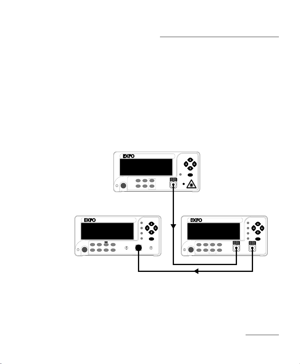
Performing Typical Tests with Your PM-1600
High-Speed Power Meter 59
Testing Instrument Linearity
When verifying instrument linearity, a linear variable attenuator (e.g.,
FVA-3100) is also required. Before verifying the linearity of an optical
detector, you must confirm the linearity of the attenuator being used.
Confirming the Linearity of the Attenuator Being
Used
Before getting started, you need a stable source (FLS-2100), a variable
attenuator, a PM-1600, two test jumpers, and appropriate connector
adapters.
To confirm the linearity of the attenuator being used,
1. Connect the instruments as shown below.
2. With all instruments set to the same wavelength and the attenuator set
to minimum attenuation, take a PM-1600 reference measurement and
switch to relative display. Also, switch the attenuator to relative display
mode.
OPTICAL LIGHT SOURCE
FLS-2100
On/Off
ENTER
CW Up
λ
Modulation Down
Store
Setup
FLS-2100
Attenuation
ACTIVE
VARIABLE ATTENUATOR
FVA-3100
Offset
ENTER
Abs Up Shutter
Rel
λ
Down Attenuation
Program
Setup
FVA-3100
Step
In
Out
HIGH-SPEED POWER METER
PM-1600
dB W/W
ENTER
dBm/W Ref
Null
Display
Range
λ
Avg Sh ift
Store
Recall
Program
Setup
Analog Out
C1
Ext. Trig
PM-1600
Page 70

Performing Typical Tests with Your PM-1600
60 PM-1600
Characterizing an Optical Switch
3. At this time, both the attenuator and power meter will display 0.000 dB.
Increase the attenuation using constant step sizes while recording the
values from both displays (attenuator and power meter) at each step.
Continue until the power meter indicates around −55 dB. The recorded
values at each step should follow within permitted tolerances. If the
values do not follow, there is a problem with the equipment setup or
with one of the instruments. Before proceeding any further, the
problem must be solved.
Testing the Linearity of an Optical Detector
Once the test configuration and instruments are properly set up (see
Confirming the Linearity of the Attenuator Being Used on page 59), you can
start testing for component linearity.
To test the linearity of the detector,
1. Disconnect the PM-1600 from the circuit as shown in the figure on
page 59 and replace it with the detector being tested.
2. Reset the attenuator to minimum attenuation.
3. Increase the attenuation on the attenuator with constant step sizes,
while recording the output read by the detector at each step.
4. When completed, the data can be analyzed to determine the linearity
of the detector.
Characterizing an Optical Switch
The high sampling rate, fast stabilization, and trigger capability of the
PM-1600 can be used simultaneously to easily characterize optical
switches.
The figure displayed in Testing Repeatability section on page 61 displays a
simple test station for a 1 x 2 optical switch. A light source is connected to
the optical switch common terminal. Each optical output of the switch is
connected to a detector of a PM-1600 Dual-Channel Power Meter. This test
setup can be used to test both the repeatability and the settling time of the
Page 71

Performing Typical Tests with Your PM-1600
High-Speed Power Meter 61
Characterizing an Optical Switch
optical switch. For the latter test, the electrical signal that is used to
command the switch is also connected to the external trigger input of the
PM-1600.
Testing Repeatability
The procedure to test the repeatability of an optical switch is relatively
simple. First, a reference measurement must be taken on each channel.
Repetitive transitions of the switch must then be performed and the total
deviation from the reference points will be considered as switch
repeatability.
To test repeatability,
1. Connect the instruments as shown below.
2. Set the power meter channels to the same wavelength as the source.
3. Set the power meter channels to Autorange mode.
4. Set the switch to the first position and take a reference measurement
on the power meter, selecting the active channel (the channel in
which the switch has a minimum insertion loss).
5. Set the switch to the second position and take a reference
measurement on the power meter, selecting the active channel.
HIGH-SPEED POWER METER
PM-1600
dB W/W
ENTER
dBm/W Ref
Null
Chan
Range
λ
Avg Sh ift
Store
Recall
Program
Setup
Analog Out
C1
C2 Ext. Trig
Display
PM-1600
OPTICAL LIGHT SOURCE
FLS-2100
On/Off
ENTER
CW Up
λ
Modulation Down
Store
Setup
FLS-2100
Attenuation
ACTIVE
DUT
(optical switch)
Control signals
Page 72

Performing Typical Tests with Your PM-1600
62 PM-1600
Characterizing an Optical Switch
6. Change the switch position from one channel to the other. For each
channel, take note of the relative power measurement when the
channel is active.
7. For each channel, the total switch deviation will be the highest positive
deviation minus the highest negative deviation relative to the original
reference (taken at step 4). The repeatability of the switch insertion
loss may be expressed as ± (total deviation in dB)/2.
Testing the Settling Time
The triggering and fast stabilization of the PM-1600 can be used to capture
fast power transitions. A good example of this is the optical switch settling
time measurement. When an electrical control signal for the switch is
available, a settling time including the electronics response time can be
measured. This is done by controlling the PM-1600 remotely to easily
retrieve the acquisition data (see Controlling the PM-1600 Automatically or
Remotely on page 67).
To measure the settling time,
1. Connect the instruments as shown below.
2. Set the power meter channel to the same wavelength as the source.
HIGH-SPEED POWER METER
PM-1600
dB W/W
ENTER
dBm/W Ref
Null
Chan
Range
λ
Avg Sh ift
Store
Recall
Program
Setup
Analog Out
C1 C2
Ext. Trig
Display
PM-1600
OPTICAL LIGHT SOURCE
FLS-2100
On/Off
ENTER
CW Up
λ
Modulation Down
Store
Setup
FLS-2100
Attenuation
ACTIVE
DUT
(optical switch)
Control signals
Page 73

Performing Typical Tests with Your PM-1600
High-Speed Power Meter 63
Using the External Trigger
3. Set the power meter channels to the proper manual range, making
sure that no saturation occurs on the active channel.
4. Select the highest Single sampling rate (4096 samples per second).
5. Set the acquisition to be externally triggered.
6. Set the optical switch to initial position.
7. Start the acquisition.
8. Activate the electrical control signal, which acts as a trigger for the
PM-1600. The PG marker, in measurement mode, will be displayed
until the switch transition is totally acquired.
9. Retrieve the data by remote control and determine the switch time
from the initial channel to the target channel.
10. Repeat steps 6 to 9 for each transition to be characterized.
This chapter describes how to use the external trigger and analog output of
the PM-1600 High-Speed Power Meter.
Both the external trigger and analog output are easily accessible from the
front panel of the power meter and use standard BNC connectors.
Using the External Trigger
The external trigger is used to synchronize or stimulate the acquisition of
power measurements with an electrical signal (TTL level). Acquisitions at
up to 4096 Hz can be performed. The use of an external trigger requires a
programmed acquisition and selection of a manual power range.
Page 74
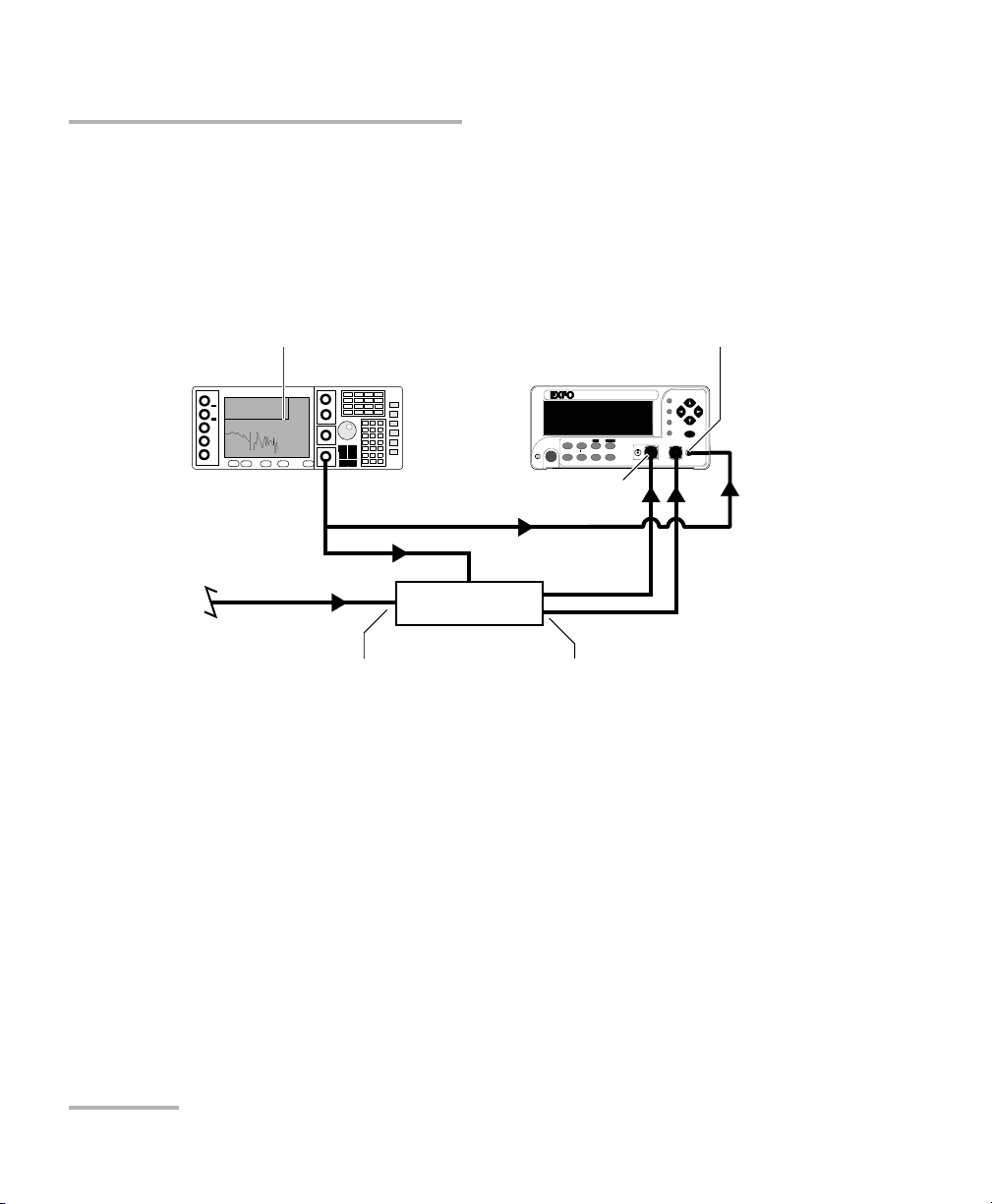
Performing Typical Tests with Your PM-1600
64 PM-1600
Using the External Trigger
Connecting a TTL Source to the External Trigger
A synchronizing signal from a signal generator or from a control circuit may
be connected to the external trigger input of the PM-1600 if it does not
exceed TTL levels. The illustration below displays a typical signal generator
connection setup.
External Trigger and Data Acquisition
To prepare an externally triggered acquisition,
1. Make sure a sampling rate from 512 Hz to 4096 Hz and a manual power
range are selected.
2. Follow the instructions in Programming Triggered Acquisitions on
page 49.
3. When you enable the externally triggered acquisition with Start
Program, the acquisition will wait for the voltage transition to occur
before storing the data in memory. If a delay was set, the acquisition
will first wait until the countdown has expired and then until the trigger
condition is met.
4.000 000 000n GHz
6.00 dBm
Optical power input
DUT
(e.-o. component)
HIGH-SPEED POWER METER
PM-1600
dB W/W
ENTER
dBm/W Ref
Null
Chan
Range
λ
Avg Shift
Store
Recall
Program
Setup
Analog OutC1 C2 Ext. Trig
Display
PM-1600
Signal generator
External trigger input
Optical input
Optical output
Page 75

Performing Typical Tests with Your PM-1600
High-Speed Power Meter 65
Using the Analog Output
Using the Analog Output
The analog output provides an electrical signal proportional to the optical
power input on the detector. On a dual-channel high-speed power meter,
this is only available for channel #1.
The analog output signal is the redirection of the signal after the first
amplification stage. Do not use the analog output while in Autorange mode
(see Setting Measurement Range on page 22) because the gain scales of
the first amplification stage are constantly changed to optimize
signal-to-noise ratio.
The following two figures illustrate typical use of the analog output.
HIGH-SPEED POWER METER
PM-1600
dB W/W
ENTER
dBm/W R ef
Null
Chan
Range
λ
Avg Shif t
Store
Recall
Program
Setup
Analog OutC1C2 Ext. Trig
Display
PM-1600
Digital oscilloscope
Analog output
HIGH-SPEED POWER METER
PM-1600
dB W/W
ENTER
dBm/W R ef
Null
Chan
Range
λ
Avg Shif t
Store
Recall
Program
Setup
Analog Out
C1 C2
Ext. Trig
Display
PM-1600
Analog output
Data logger
Page 76

Performing Typical Tests with Your PM-1600
66 PM-1600
Using the Analog Output
The user interface can be used to determine the operating power levels
and to optimize the analog output range. Choose the optimum power
range for your application. The following table provides the voltage vs.
power information for each available manual range.
Manual Range Power vs. Voltage
a
a. At 1310 nm.
LR1, HR1 2.15V ±25%bat 18.30 dBm
c
b. Large uncertainty is due to detector responsivity at 1310 nm.
c. Not guaranteed due to detector saturation.
LR2, HR2 2.15 V ± 25 %bat 9.90 dBm
c
LR3, HR3 2.15 V ± 25 %bat −10.09 dBm
LR4, HR4 2.15 V ± 25 %
b
at −29.87 dBm
LR5 2.15 V ±25%
b
at −49.61 dBm or at 44.94
dBm for PM-16XXW models
LR6 2.15 V ±25%
b
at -69.61 dBm or at 64.10
dBm for PM-16XXW models
Page 77

Controlling the PM-1600 Automatically or Remotely
High-Speed Power Meter 67
8 Controlling the PM-1600
Automatically or Remotely
The PM-1600 can be remotely controlled by either
➤ a GPIB interface (through a GPIB cable connected to the GPIB port), or
➤ an RS-232 interface (through a serial cable connected to the serial
port).
The commands used in the two protocols are almost the same and are
described in the following pages. When the PM-1600 is being remotely
controlled, the RM marker appears to the right of the display.
Note: If you have already designed a GPIB program to control a high-speed
power meter from EXFO’s IQ Series (IQ-1600), you can reuse certain
sections for the PM-1600.
Page 78
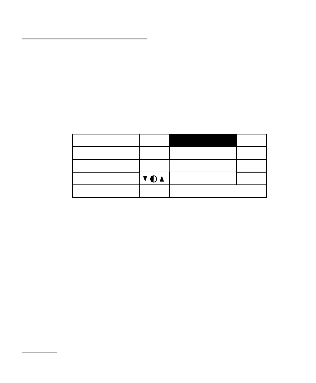
Controlling the PM-1600 Automatically or Remotely
68 PM-1600
Setting Up the PM-1600 for Remote Control
Setting Up the PM-1600 for Remote Control
To remotely control the PM-1600, you need to set a GPIB address or
activate the RS-232 port.
1. Press Setup to access the Setup menu.
2. Press ENTER to access the System Setup menu.
3. Use the up/down or left/right arrow keys, select RS232 / GPIB. The
current setting is displayed.
4. Press ENTER, then use the up/arrow keys to toggle between GPIB and
RS232.
5. Press ENTER to confirm.
6. If you selected RS232, the GPIB Addr. menu option is deactivated
(N.A. is displayed). If you selected GPIB and you are not satisfied with
the currently selected GPIB address, press ENTER, use the up/arrow
keys to select the required address (between 1 and 30), and then
confirm by pressing ENTER.
Note: If GPIB is currently selected and you want to specify a GPIB address, you
can skip steps 4 and 5 above.
Exit
Sampling
Refresh Rate
Backlight
Contrast
Video Mode
256Hz
16Hz
ON
STD
RS232 / GPIB
GPIB Addr.
Save
Recall
GPIB
15
# 3
# 3
Page 79

Controlling the PM-1600 Automatically or Remotely
High-Speed Power Meter 69
Communication Parameters
Communication Parameters
For GPIB Communication
Termi nate R ead on EOS
a
a. “End of String”
Ye s
Set EOI
b
with EOS on Writes
b. “End or Identify”
Ye s
Type of compare on EOS 8-bits
EOS byte 0Ah
Send EOI at end of Writes Yes
GPIB primary address See page 68
GPIB secondary address None
For RS-232 Communication
EOS bytes 0Ah
Baud rate 9600 bps
Pari ty Non e
Data bits 8 bits
Stop bits 1 bit
Flow control None
Activation See page 68
Page 80

Controlling the PM-1600 Automatically or Remotely
70 PM-1600
Standard Status Data Structure
Standard Status Data Structure
The figures below illustrate the four common Status and Enable registers
as defined by IEEE 488.2. These diagrams are a useful aid in understanding
the general commands and how a service request (SRQ) is generated. The
four registers are
➤ Standard Event Status Register (ESR)
➤ Standard Event Status Enable Register (ESE)
➤ Status Byte Register (STB)
➤ Service Request Enable Register (SRE)
Bit ESR ESE STB SRE
0 Operation
Complete
Operation
Complete
Source Status Source Status
1 Request Control Request Control N/A N/A
2 Query Error Query Error Error Bit Error Summary
Bit
3 Device
Dependent Error
Device
Dependent Error
Questionable
Status
Questionable
Status
4 Execution Error Execution Error Message
Available
Event Status
Summary Bit
5 Command Error Command Error Event Status
Summary Bit
Message
Available
6 User Request User Request Master Summary
Status
Request Service/
Master Summary
Status
7 Power On Power On Operation Status Operation Status
Page 81

Controlling the PM-1600 Automatically or Remotely
High-Speed Power Meter 71
Standard Status Data Structure
&
&
&
&
&
&
&
&
OR
Standard Event Status
Register (ESR)
Standard Event
Status Enable
Register (ESE)
&
&
&
&
&
&
&
OR
Status Byte
Register
(STB)
Service Request Enable
Register (SRE)
7 6 5 4 3 2 1 0
7 6 5 4 3 2 1 0
7 6 5 4 3 2 1 0
7 5 4 3 2 1 0
ESB MAV EB
ESB MAV
RQS
6
MSS
Service Request
Generation
{
{
Output Queue not Empty
read by serial poll
read by *STB?
PON
OPC
URQ
RQCQYE
DDE
EXECME
PON
OPC
URQ
RQCQYE
DDE
EXECME
Page 82

Controlling the PM-1600 Automatically or Remotely
72 PM-1600
Command Structure
An SRQ is forced when a bit is set in the STB. At the same time the
corresponding SRE bit is set. When the SRQ is generated, the RQS bit is set
to 1, and remains set until read by a serial poll. Once the RQS is read, it
returns to 0.
Command Structure
The GPIB and RS-232 commands follow the guidelines determined by the
Standard Commands for Programmable Instruments (SCPI) consortium.
For example, the command syntax
FORM:READ[:DATA]<space><digit>
is used to change the measurement display resolution (i.e., the number of
digits after the decimal point) on the PM-1600.
In this particular example,
➤ FORM identifies that the command is part of the SCPI FORMat subset
of commands
➤ READ and DATA are keywords that define the function of the command
➤ [ ] indicates that a keyword or parameter is optional
➤ <space> is included to indicate that a space is required
➤ <digit> is the command parameter
Keywords must be separated by a colon. A typical command would be
FORM:READ:DATA 1
This command instructs the PM-1600 to display a power measurement
with 1 digit after the decimal point.
Note: It is recommended that you retrieve the response immediately after each
query.
Page 83

Controlling the PM-1600 Automatically or Remotely
High-Speed Power Meter 73
General Commands—Quick Reference
General Commands—Quick Reference
The PM-1600 recognizes the main commands identified in IEEE 488.2.
These commands, as well as some optional general commands, the
programming state commands, and some status queries, are summarized
in the table below. For full explanation, see General Commands on
page 111.
Command Function
*CLS Clear status command
*ESE Standard event status enable command
*ESE? Standard event status enable query
*ESR? Standard event status register query
*IDN? Identification query
*LOK Set Remote Lockout programming state
*OPC Operation complete command
*OPC? Operation complete query
Page 84

Controlling the PM-1600 Automatically or Remotely
74 PM-1600
General Commands—Quick Reference
*REM
a
Set Remote programming state
*RST Reset command
*SRE Service request enable command
*SRE? Service request enable query
*STB? Read status byte query
SYST:ERR? Error status query
SYST:VERS? Identification status query
*TRG (Not supported)
*TST? Self-test query
*WAI (Not supported)
a. This command can only be used with RS-232 communication.
Command Function
Page 85

Controlling the PM-1600 Automatically or Remotely
High-Speed Power Meter 75
Specific Commands—Quick Reference
Specific Commands—Quick Reference
The following table contains a summary of the PM-1600 specific
commands. If you need more information about these specific commands,
see Specific Commands on page 118.
Command
Parameter/
Response
Description
ABOR — Stops measurements
FETC [SCAL] POW DC? (+999.9999E±99) for
W and W/W units
(±999.9999) for dBm
and dB units
Gets stored value
FORM READ [DATA]
a
<0|1|2|3|4|5> Sets display resolution
INIT AUTO
a
<0|1>,<CONT|
NCON>
Starts/stops
programmed
acquisition
AUTO? (0|1) Checks if programmed
acquisition is in
progress
CONT <0|1> Starts/stops
measurements
CONT? (0|1) Checks if
measurements are in
progress
[IMM] — Stores single
measurement
INST NSEL
a
<channel#> Sets channel number
NSEL? (channel#) Gets channel number
Page 86

Controlling the PM-1600 Automatically or Remotely
76 PM-1600
Specific Commands—Quick Reference
READ [SCAL] POW DC? (+999.9999E±99) for
W and W/W units
(±999.9999) for dBm
and dB units
Stores and gets value
ALL POW DC? (+999.9999E±99) for
W and W/W units
(±999.9999) for dBm
and dB units
Returns the power of
both channels in their
respective current unit
SENS AVER COUN
a
<999> Sets number for data
averaging
COUN? (999) Gets number for data
averaging
[STAT]
a
<0|1> Sets data averaging
STAT? (0|1) Checks if data
averaging is active
CORR COLL ZERO
a
Performs null
measurement
OFFS [MAGN]
a
<−5.999 to +6.000>
[DB]
<0.2512 to 3.9811>
[W/W]
Sets correction factor
OFFS MAGN?
a
(+9.9999E±99) for
W and W/W units
(±9.9999) for dBm
and dB units
Returns correction
factor
FREQ [CONT]
a
<value> [HZ] Sets low acquisition
rate
CONT? (999.999) Gets low acquisition
rate
Command
Parameter/
Response
Description
Page 87

Controlling the PM-1600 Automatically or Remotely
High-Speed Power Meter 77
Specific Commands—Quick Reference
SENS FREQ CONT CATA? (999.999;999.999;...) Lists low acquisition
rates
NCON
a
<value> [HZ] Sets programmed
acquisition rate
NCON? (9999.999) Gets programmed
acquisition rate
NCON CATA? (9999.999;
9999.999...)
Lists programmed
acquisition rates
POW RANG? (±99.99) [dBm]
(+999.9999E+99)
[W]
Gets range
RANG AUTO
a
<0|1> Sets Autorange
AUTO? (0|1) Checks if Autorange is
active
HIGH
a
<1|2|3|4> Sets manual high range
LIST? (±99.99) [dBm]
(+999.9999E+99)
[W]
Lists ranges
LOW
a
<1|2|3|4|5|6> Sets manual low range
REF
a
±999.9999 [dBm]
+
999.9999E±99[W]
Sets user reference
REF? ±999.9999 [dBm]
+
999.9999E±99[W]
Gets reference
REF DISP
a
—Sets new reference
REF STAT
a
<0|1> Sets absolute or relative
mode
REF STAT? (0|1) Gets absolute or
relative mode
Command
Parameter/
Response
Description
Page 88

Controlling the PM-1600 Automatically or Remotely
78 PM-1600
Specific Commands—Quick Reference
SENS POW UNIT
a
<DBM|W|0|1> Sets power unit
UNIT? (0|1) Gets power unit
WAVE
a
<value> [NM] Sets wavelength
WAVE? (9999.99) [NM] Gets wavelength
TRAC DATA? (+999.9999E±99;
+999.9999E±99;...)
[W] or (±999.9999;
±999.9999;...) [dB or
dBm]
Gets measurements
POIN
a
<9999> Sets number of points
POIN? (9999) Gets number of points
TRIG SEQ LEV
a
<+999.9999E±99>
[W] or <±999.9999>
[dBm]
Sets trigger level
LEV? (+999.9999E±99)
[W] or <±999.9999>
[dBm]
Gets trigger level
SLOP
a
<POSITIVE|
NEGATIVE>
Sets trigger edge
SLOP? (POSITIVE|
NEGATIVE)
Gets trigger edge
SOUR
a
<EXTERNAL|
INTERNAL1|2>
Sets trigger source
SOUR? (EXTERNAL|
INTERNAL1|2)
Gets trigger source
Command
Parameter/
Response
Description
Page 89

Controlling the PM-1600 Automatically or Remotely
High-Speed Power Meter 79
Specific Commands—Quick Reference
TRIG SEQ STAT <0|1> Activates/deactivates
trigger
STAT? (0|1) Checks if trigger is
active
UNIT POW <0|1|2|3|
DB|DBM|W|W/W>
Sets display unit
a. These commands are not executed if a data acquisition is in progress. The “Acquisition already running”
message will be returned.
Command
Parameter/
Response
Description
Page 90

Controlling the PM-1600 Automatically or Remotely
80 PM-1600
Error Messages
Error Messages
System and device-specific errors are managed by the PM-1600. The
generic format for error messages is illustrated in the following figure.
As shown in the figure above, the message contains three parts: the error
number, the error description, and device-dependent information. All error
messages are stacked in a FIFO buffer. When there is at least one message
in the buffer, bit 2 of the Status Byte Register is set to 1. Use the SYST:ERR?
query to read the most recent message. The error message buffer is
initialized when starting up the PM-1600, when executing the *CLS
command, or when reading the last message stored in the buffer.
➤ Error messages ending with a negative number are SCPI-based errors.
➤ Error messages ending with a positive number are specific to the
PM-1600.
<Error number>
,
“
<Error description>
;
<Device-dependent
”
information>
Page 91

Controlling the PM-1600 Automatically or Remotely
High-Speed Power Meter 81
SCPI Management Errors (System Errors)
SCPI Management Errors (System Errors)
Error
Number
Description Probable Cause
−100 “Command error” An error occurred while validating a
command.
−101 “Undefined header” Unknown command.
−102 “Missing parameter” A required data parameter was not
detected.
−103 “Parameter not allowed” Too many parameters were detected
for the specified command.
−104 “Data type error” A data parameter is not the expected
data type.
−200 “Execution error” An error occurred while executing the
command.
−300 “Device dependent error” A command has taken longer than
expected to complete execution.
−400 “Query error” Attempt to read an empty buffer or
buffer data has been lost.
−500 “System error” System is out of memory.
Page 92

Controlling the PM-1600 Automatically or Remotely
82 PM-1600
PM-1600 Error Messages
PM-1600 Error Messages
Error
Number
Description Probable Cause
1602 “Invalid channel” The specified channel number is invalid.
1603 “Light on detector” A nulling command has been attempted
with light reaching the detector.
1604 “Invalid parameter” The high-speed power meter has
received a data parameter that it was not
expecting.
1605 “Parameter out of range” The high-speed power meter has
received a data parameter outside the
valid range.
1606 “Acquisition already running” A command was sent while an
acquisition was in progress.
1607 “Acquisition not running” A command to stop an acquisition was
sent with no acquisition in progress.
1612 “Invalid unit” The specified unit is not valid.
1615 “Invalid sampling rate” The selected sampling rate is not
compatible with the current acquisition
mode (continuous or single).
1616 “Module timeout on nulling” The nulling process could not be
performed.
1617 “Automatic range cannot be used
for programmed acquisition”
A manual range must be selected for a
programmed acquisition.
1618 “Command not processed:
internal error”
An internal error caused the command to
fail.
1619 “Segment not allowed” No data in the segment.
1620 “No data logged” No data was logged.
Page 93

High-Speed Power Meter 83
9 Customizing the PM-1600
Display
Setting Backlight
In certain circumstances, you might want to deactivate the backlight that
illuminates the display.
To deactivate the backlight,
1. Press Setup to access the Setup menu.
2. Press ENTER to access the System Setup menu.
3. Use the up/down or left/right arrow keys to select Backlight.
4. Press ENTER to access the backlight edit box.
5. Use the up/down arrow keys until the backlight value changes to OFF.
Note: To reactivate the backlight, follow steps 1 to 5, except that the backlight
value has to be set to ON.
Note: You can deactivate the backlight while in the power measurement mode by
pressing Shift, then the left arrow key. To subsequently reactivate the
backlight, press Shift, then the right arrow key.
Page 94

Customizing the PM-1600 Display
84 PM-1600
Setting Display Contrast
Setting Display Contrast
To set the contrast,
1. Press Setup to access the Setup menu.
2. Press ENTER to access the System Setup menu.
3. Use the up/down or left/right arrow keys to select Contrast.
4. Press ENTER to access the contrast edit box.
5. Use the up/down arrow keys to adjust the contrast as required.
6. Confirm the contrast adjustment by pressing ENTER.
Note: You can adjust the display contrast from within the power measurement
mode by pressing Shift, then the up/down arrow keys. To confirm the
contrast adjustment, press Shift again.
Choosing Video Mode
To set the video mode,
1. Press Setup to access the Setup menu.
2. Press ENTER to access the System Setup menu.
3. Use the up/down or left/right arrow keys to select Video Mode.
4. Press ENTER to access the video mode edit box.
5. Use the up/down arrow keys to set the required video mode.
Page 95
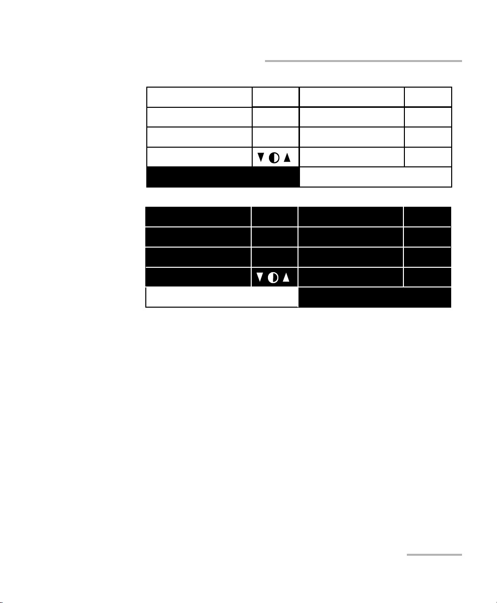
Customizing the PM-1600 Display
High-Speed Power Meter 85
Choosing Video Mode
6. Press ENTER to confirm the video mode.
Exit
Sampling
Refresh Rate
Backlight
Contrast
Video Mode
256Hz
16Hz
ON
STD
RS232/GPIB
GPIB Addr.
Save
Recall
GPIB
15
# 3
# 3
Exit
Sampling
Refresh Rate
Backlight
Contrast
Video Mode
256Hz
16Hz
ON
INV
RS232/GPIB
GPIB Addr.
Save
Recall
GPIB
15
# 3
# 3
Page 96

Customizing the PM-1600 Display
86 PM-1600
Choosing Video Mode
System Parameters
Refresh rate 4 Hz
Sampling rate 4 Hz
Backlight ON
Video mode Standard
RS-232/GPIB address 12
Active channel #1
Active program #1
Shortlisted wavelengths Six wavelengths (see note
on page 26) with CF OFF
Program Parameters
Delay 00h00m00s
Duration 00h00m01s
Trigger Inactive
Sampling rate 1 Hz
Number of points 0001/Ch.
Page 97

High-Speed Power Meter 87
10 Maintenance
To help ensure long, trouble-free operation,
➤ Keep the unit free of dust.
➤ Clean the unit casing with a tissue that has been slightly dampened
with water.
➤ Store unit at room temperature in a clean and dry area.
➤ Keep the unit out of direct sunlight.
➤ Avoid high humidity or significant temperature fluctuations.
➤ If any liquids are spilled on or into the unit, turn off the power
immediately and let the unit dry completely.
➤ Avoid unnecessary shocks and vibrations.
Cleaning the Front Panel
Clean the front panel of the module regularly to avoid build-up of dust, dirt,
and other foreign substances.
To clean the front panel,
1. Gently wipe the front panel with a cloth that has been dampened with
soapy water.
2. Rinse the front panel with a cloth that has been dampened with water.
3. Dry with a clean wiping cloth.
WARNING
Use of controls or adjustments or performance of procedures other
than those specified herein may result in hazardous radiation
exposure.
Page 98

Maintenance
88 PM-1600
Cleaning Fixed Connectors
Cleaning Fixed Connectors
Regular cleaning of connectors will help maintain optimum performance.
There is no need to disassemble the module.
To clean fixed connectors,
1. Fold a lint-free wiping cloth in four to form a square.
2. Moisten the center of the lint-free wiping cloth with only one drop of
isopropyl alcohol.
3. Gently wipe the connector threads three times with the folded and
moistened section of the wiping cloth.
4. With a dry lint-free wiping cloth, gently wipe the same surfaces three
times with a rotating movement.
5. Throw out the wiping cloths after one use.
IMPORTANT
To help keep the various connectors and adapters clean, EXFO
recommends that you install protective caps when the unit is not in
use. You should also clean the fiber ends before every connection.
IMPORTANT
Alcohol may leave traces if used abundantly. Avoid contact between
the tip of the bottle and the wiping cloth, and do not use bottles
that distribute too much alcohol at a time.
IMPORTANT
Isopropyl alcohol takes approximately ten seconds to evaporate.
Since isopropyl alcohol is not absolutely pure, evaporation will
leave microscopic residue. Make sure you dry the surfaces before
evaporation occurs.
Page 99

Maintenance
High-Speed Power Meter 89
Cleaning Fixed Connectors
6. Moisten a cleaning tip (2.5 mm tip) provided by EXFO with only one
drop of isopropyl alcohol.
7. Slowly insert the cleaning tip into the connector until it reaches the
ferrule inside (a slow clockwise rotating movement may help).
8. Gently turn the cleaning tip one full turn.
9. Continue to turn as you withdraw the cleaning tip.
10. Perform steps 7 to 9 again, but this time with a dry cleaning tip (2.5 mm
tip provided by EXFO).
Note: Make sure that you do not touch the soft end of the cleaning tip, and verify
the cleanliness of the cotton tip.
11. Throw out the cleaning tips after one use.
IMPORTANT
Alcohol may leave traces if used abundantly. Avoid contact between
the tip of the bottle and the cleaning tip, and do not use bottles
that distribute too much alcohol at a time.
7
8
9
Page 100

Maintenance
90 PM-1600
Cleaning Connectors Equipped with EUI/EUA Adapters
Cleaning Connectors Equipped with EUI/EUA
Adapters
Regular cleaning of connectors equipped with EUI/EUA adapters will help
maintain optimum performance. There is no need to disassemble the unit.
To clean connectors,
1. Remove the EUI/EUA adapter from the module to expose the optical
connector baseplate and ferrule.
2. Use a lint-free wiping cloth and deposit only one drop of isopropyl
alcohol on it.
IMPORTANT
If any damage occurs to internal connectors, the module casing will
have to be opened and a new calibration will be required.
IMPORTANT
Alcohol may leave traces if used abundantly. Avoid contact between
the tip of the bottle and the wiping cloth, and do not use bottles
that distribute too much alcohol at a time.
Push
Turn
Pull
1
2
3
 Loading...