

eXact PipeCut+Bevel 280 Pro Series, PipeCut+Bevel 360 Pro Series, PipeCut+Bevel 460 Pro Series Operating Instructions Manual
Page 1
English
EN
Operating Instructions
PipeCut+Bevel 280 Pro Series
360 Pro Series
460 Pro Series
These instructions are translation of the original instructions written in Finnish language.
All instructions are available on web-site: exacttools.com/manuals
Patents: US 7,257,895, JP 4010941, EP 1301311, FI 108927, KR 10-0634113
Page 2

English
2
Exact PipeCut+Bevel 280 / 360 / 460 Pro Series
Data of Exact PipeCut saw blades
1. Exact TCT saw blades are for cutting steel,
copper, aluminum and all kind of plastics pipe
materials. Exact TCT saw blades can be
sharpened.
2. Exact CERMET saw blades are for cutting
stainless steel, acid proof materials, steel,
copper, aluminum and all kind of plastic pipe
materials. Exact CERMET saw blades can be
sharpened.
3. Exact CERMET ALU saw blades are for cutting
all kind of aluminum and plastic pipe materials.
Exact CERMET ALU saw blades can be
sharpened.
4. Exact TCT P blades are for cutting all kind of
plastic pipe materials. Exact TCT P saw blades
can be sharpened.
5. Exact DIAMOND X discs are for cutting Cast or
Ductile Iron only. Exact DIAMOND X discs
cannot be sharpened.
280 Pro Series / 360 Pro Series / 460 Pro Series
speed control recommendations:
Stainless steel I
Steel II
Cast-iron II
Plastics II
Declaration of Conformity
We declare under our sole responsibility that the pipe cutting machines
Exact PipeCut+Bevel 280 / 360 / 460 Pro Series
Described under” Technical Data” are in conformity with the following standards or standardization
documents:
IEC 62841-1:2014, IEC 62841-2-5:2014, EN 62841-1:2015, EN 62841-2-5:2014, EN 55014-1,
EN 55014-2, EN 61000-3-2, EN 61000-3-3
These instructions are translation of the original instructions written in Finnish
For more information, please contact Exact Tools at the following address:
The technical file is available at the address underneath:
The person authorized to compile the technical file:
Seppo Makkonen, chairman of the board (seppo.makkonen@exacttools.com)
Helsinki, 01.02.2018
Seppo Makkonen, chairman of the board Exact Tools Oy
Särkiniementie 5 B 64
FI-00210 Helsinki, Finland
Page 3
English
3
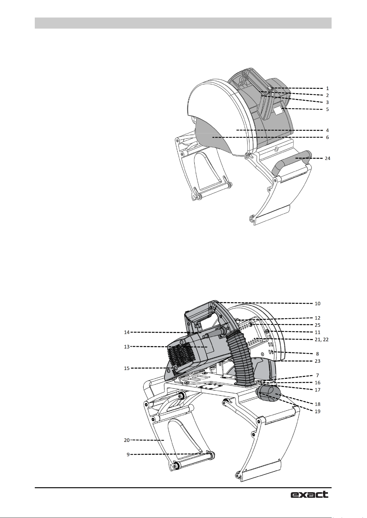
FIGURE A
1 Unlocking switch
2 Power switch
3 Power switch locking lever
(in front of the switch)
4 Blade guard cover
5 Overload indicator light
6 Moving blade-guard
7 Adjusting screws
8 Laser pointer box
9 Adjusting wheel
10 Handle
11 Blade guard screw
12 Lock pin
13 Plate
14 Motor unit
15 Blade RPM speed control
16 Adjustment arrow
17 Adjustment slot
18 Gripping device adjusting knob
19 Gripping device locking collar
20 Gripping device
21 Laser pointer batteries
(inside the blade protection)
22 Battery seat cover
(inside the blade protection)
23 Laser Pointer
(inside the blade protection)
24 Handle to carry the saw
25 Laser switch
Page 4
English
4
FIGURE A2
Page 5

Package contents
English
5
Contents
Information
Technical data 6
Package contents 7
Safety
Safety instructions 8
Operation
Functional description 11
Product features 12
Before operating the tool 13
Connection to mains power supply 13
Setting the pipe on supports 13
Attaching the pipe saw to the pipe 13
Piercing the pipe wall 14
Cutting around the pipe 14
Overload protection and RPM adjustment 15
Explanation if indicator lights 15
Improving possible misalignment of the cut 15
Cutting result adjustment on Exact 16
PipeCut+Bevel 280 / 360 / 460 Pro Series
Installing and changing the blade 17
Maintenance and servicing instructions 17
Environment / disposal 18
Guarantee / guarantee conditions 18
Tips for using Exact PipeCut saws 18
Extra equipment 19
Theoretical cutting depths 19
Instructions updated 18.10.2019
Page 6

Safety instructions
English
6
Voltage
230 V– 240 V / 50–60 Hz / 100 V–120 V 50–60Hz
Power
2500 W– 230 V– 240 V / 15 А-100 V– 120 V
No-load speed
I (low) = 1900/min, II (high) = 2885 /min
Blade diameter
140 mm (5.6"), 165 mm (6.50"), 180 mm (7.2"),190 mm (7.6")
Mounting bore
62 mm (2.44")
Weight
PipeCut+Bevel 280 Pro Series 16 kg (35 lbs),
PipeCut+Bevel 460 Pro Series 18,5 kg (42 lbs)
Range of use PipeCut+Bevel 280 Pro Series
40 mm–280 mm (1.6"–11")
Range of use PipeCut+Bevel 360 Pro Series
75 mm–360 mm (3.0"–16")
Range of use PipeCut+Bevel 460 Pro Series
100 mm–460 mm (4"–17.5")
Max. pipe wall, plastics and other soft materials
45 mm (1.8”) 280
Max. Pipe wall 230V, steel, iron
20 mm / 0.78”
Max. Pipe wall 120V, steel, iron
12 mm / 0.47”
Protection class
⧈ / II
Spindle lock
Yes
Speed preselection
Yes
Constant electronic control
Yes
Overload Protection
Yes
Reduced starting current
Yes
Vibration, A
”cutting metal”
3,2 m/s2
Vibration uncertainty, K
0,3 m/s2
LpA (sound pressure)
101,0 dB(A)
KpA (sound pressure uncertainty)
3 dB(A)
LWA (acoustic power)
112,0 dB(A)
KWA (acoustic power uncertainty)
3 dB(A)
Recommended generator capacity
4,9kVA for 230V, 3kVA for 100 V-120V
Exact PipeCut+Bevel 280 / 360 / 460 Pro Series
PipeCut+Bevel 360 Pro Series 17,5 kg (40 lbs),
50 mm (2.0”) 360 and 460
h,M
The values given are valid for nominal voltages [U] of 230/240 V. For lower voltage and models for specific countries, these values can vary.
Page 7
Package contents
English
7
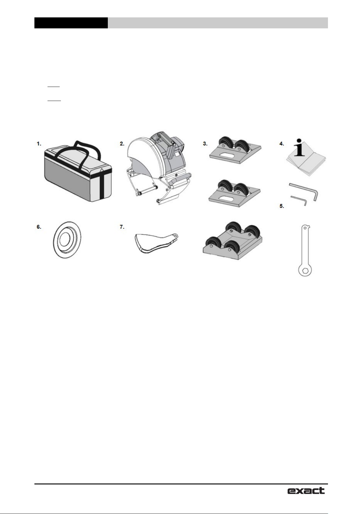
Exact PipeCut+Bevel 280 / 360 / 460 Pro Series pipe cutting systems
Package contents, please check that the package contains the following items:
1. Exact PipeCut System Shoulder Bag
2. Exact PipeCut+Bevel 280 / 360 / 460
3. Pipe Cutting supports 1 + 2 pcs. (280 4pcs aluminum)
4. Operating instructions
5. Allen key 2 pcs (5 mm and 2 mm) and blade adjusting key.
6. Exact Cut+Bevel Diamond disc 165
7. Lower blade guard with wide opening for Cut+Bevel Diamond disc
Pro Series pipe saw
Page 8

Safety instructions
English
8
Definitions: Safety instructions
The definitions below describe the level of severity for
each signal word. Please read the manual and pay
attention to these symbols
DANGER: Indicates an imminently hazardous
situation which, if not avoided, will result in serious
injury or in extreme cases a fatality
WARNING: Indicates a potentially hazardous
situation which, if not avoided, could result in serious
injury or in extreme cases a fatality
CAUTION: Indicates a potentially hazardous
situation which, if not avoided, may result in minor or
moderate injury.
Please notice the article number on the type plate of
your machine. The trade names of the individual
machines may vary.
Only for power tools without reduced starting
current: Starting cycles generate brief voltage drops.
Interference with other equipment/machines may
occur in case of unfavorable mains system
conditions. Malfunctions are not to be expected for
system impedances below 0.36 ohm.
Noise/vibration Information
The vibration emission level given in this information
sheet has been measured in accordance with a
standardized test given in EN62481-2-5:2014
Use ear protection!
NOTICE: Indicates a practice not related to
personal injury which, if not avoided, may result
in property damage.
Denotes risk of electric shock.
Symbols found on the machine.
Use ear protection.
Use gloves.
Read instructions before use.
Laser radiation: Do not look directly into
beam.
Saw blade: Saw blade behind this cover, do not insert
fingers or other body parts inside this cover.
Operating, safety and service
instructions
Read these operating, safety and service
instructions carefully before operating the pipe
saw.
Store these instructions in a place where all
pipe saw operators have access. In addition to
these instructions official work, health and
safety rules must be followed. Exact PipeCut is
for professional use only.
Vibration level values (sum of vectors of three
directions) are defined in accordance with standard
EN62841-2-5:2014:
Vibration rate a
Uncertainty K = 0,3 m/s².
The vibration emission level given in this information
sheet has been measured in accordance with a
standardized test given in EN62841-2-5:2014 and
may be used to compare one tool with another. It
may be used for a preliminary assessment of
exposure.
WARNING: The declared vibration emission
level represents the level during main applications of
the tool.
However, if the tool is used for different applications,
with different accessories or poorly maintained, the
vibration emission may differ. This may significantly
increase the exposure level over the total working
period.
An estimation of the level of exposure to vibration
should also take into account the times when the
tool is switched off or when it is running but not
actually doing the job. This may significantly reduce
the exposure level over the total working period.
Identify additional safety measures to protect the
operator from the effects of vibration such as:
maintain the tool and the accessories, keep the
hands warm, organize work patterns.
WARNING:
If Exact PipeCut+Bevel 280 / 360 / 460 Pro Series
tool is used with generator or extension cords, their
minimum requirements are as follows:
Generator: minimum power of 3500 watts, if other
electrical equipment is not used at the same time.
Extension cords 230 V: The maximum length - 25
meters. Cable cross section - not less than 2,5mm ².
Extension cords 120 V: The maximum length – 82
Feet Extra Heavy Duty
“cutting metal” = 3.2 m/s ²,
h,M
Page 9

Safety instructions
English
9
General power tool safety warnings
WARNING: Read all safety warnings,
illustrations and specifications provided with this
power tool. Failure to follow all instructions listed
below may result in electric shock, fire and/or serious
injury
Save all warnings and instructions for future
reference.
The term “power tool” in the warnings refers to your
mains operated (corded) power tool or battery-operated
(cordless) power tool.
1 Work area safety
a) Keep work area clean and well lit. Cluttered or
dark areas invite accidents.
b) Do not operate power tools in explosive
atmospheres, such as in the presence of flammable
liquids, gases or dust. Power tools create sparks
which may ignite the dust or fumes.
c) Keep children and bystanders away while
operating a power tool. Distractions can cause you to
lose control.
2 Electrical safety
a) Power tool plugs must match the outlet. Never
modify the plug in any way. Do not use any adapter
plugs with earthed (grounded) power tools.
Unmodified plugs and matching outlets will reduce risk
of electric shock.
b) Avoid body contact with earthed or grounded
surfaces, such as pipes, radiators, ranges and
refrigerators. There is an increased risk of electric
shock if your body is earthed or grounded.
c) Do not expose power tools to rain or wet
conditions. Water entering a power tool will increase
the risk of electric shock
d) Do not abuse the cord. Never use the cord for
carrying, pulling or unplugging the power tool.
Keep cord away from heat, oil, sharp edges or
moving parts. Damaged or entangled cords increase
the risk of electric shock
e) Damaged cable should be changed in the
authorized service center.
f) When operating a power tool outdoors, use an
extension cord suitable for outdoor use. Use of a
cord suitable for outdoor use reduces the risk of electric
shock.
g) If operating a power tool in a damp location is
unavoidable, use a residual current device (RCD)
protected supply. Use of an RCD reduces the risk of
electric shock
h) Hold electric tools by isolated handles, because
during the operation it can connect to flush
conductor or its own cord. If tool connects to voltage-
carrying cables, voltage can pass to metal parts and it
increases the risk of electric shock.
3 Personal safety
a) Stay alert, watch what you are doing and use
common sense when operating a power tool. Do
not use a power tool while you are tired or under
the influence of drugs, alcohol or medication. A
moment of inattention while operating power tools
may result in serious personal injury.
b). Use personal protective equipment. Always
wear eye protection. Protective equipment such as
dust mask, non-skid safety shoes, hard hat, or
hearing protection used for appropriate conditions
will reduce personal injuries.
c) Prevent unintentional starting. Ensure the
switch is in the off-position before connecting to
power source and/or battery pack, picking up or
carrying the tool. Carrying power tools with your
finger on the switch or energizing power tools that
have the switch on invites accidents.
d) Never operate the tool, if blade covers are not
in place.
e) Remove any adjusting key or wrench before
turning the power tool on. A wrench or a key left
attached to a rotating part of the power tool may
result in personal injury.
f) Do not overreach. Keep proper footing and
balance at all times. This enables better control of
the power tool in unexpected situations.
g) Dress properly. Do not wear loose clothing or
jewelry. Keep your hair and clothing away from
moving parts. Loose clothes, jewelry or long hair
can be caught in moving parts.
h) Do not put your hands inside the pipe during
the operation. Take care, that no one will put
anything inside the pipe during the operation.
i) Do not let familiarity gained from frequent use
of tools allow you to become complacent and
ignore tool safety principles. A careless action
can cause severe injury within a fraction of a
second.
j) Support the pipe to cut securely. Pipe supports
are more reliable for holding the pipe than bare
hands.
k) If devices are provided for the connection of
dust extraction and collection facilities, ensure
these are connected and properly used. Use of
dust collection can reduce dust-related hazards.
Page 10

Safety instructions
English
10
4 Cutting procedures
a) DANGER: Keep hands away from cutting
area and the blade. Keep your second hand on
auxiliary handle, or motor housing. If both hands are
holding the saw, they cannot be cut by the blade.
b) Do not reach underneath the workpiece. The
guard cannot protect you from the blade below the
workpiece.
c) Adjust the cutting depth to the thickness of the
workpiece. Less than a full tooth of the blade teeth
should be visible below the workpiece.
d) Never hold the workpiece in your hands or
across your leg while cutting. Secure the
workpiece to a stable platform. It is important to
support the work properly to minimize body exposure,
blade binding, or loss of control.
e) Hold the power tool by insulated gripping
surfaces, when performing an operation where the
cutting tool may contact hidden wiring or its own
cord. Contact with a "live" wire will also make exposed
metal parts of the power tool "live" and could give the
operator an electric shock.
f) When ripping, always use a rip fence or straight
edge guide. This improves the accuracy of cut and
reduces the chance of blade binding.
g) Always use blades with correct size and shape
(diamond versus round) of arbour holes. Blades that
do not match the mounting hardware of the saw will run
off-centre, causing loss of control.
h) Never use damaged or incorrect blade washers
or bolt. The blade washers and bolt were specially
designed for your saw, for optimum performance and
safety of operation.
5 Lower guard function
a) Check the lower guard for proper closing before
each use. Do not operate the saw if the lower guard
does not move freely and close instantly. Never
clamp or tie the lower guard into the open position.
If the saw is accidentally dropped, the lower guard may
be bent. Raise the lower guard with the retracting
handle and make sure it moves freely and does not
touch the blade or any other part, in all angles and
depths of cut.
b) Check the operation of the lower guard spring. If
the guard and the spring are not operating
properly, they must be serviced before use. Lower
guard may operate sluggishly due to damaged parts,
gummy deposits, or a build-up of debris.
c) The lower guard may be retracted manually only
for special cuts such as "plunge cuts" and
"compound cuts". Raise the lower guard by the
retracting handle and as soon as the blade enters
the material, the lower guard must be released. For
all other sawing, the lower guard should operate
automatically.
Page 11

Safety instructions
English
11
d) Always observe that the lower guard is covering
the blade before placing the saw down on bench or
floor. An unprotected, coasting blade will cause the
saw to walk backwards, cutting whatever is in its path.
Be aware of the time it takes for the blade to stop after
switch is released.
6 Power tool use and care
a) Do not force the power tool. Use the correct
power tool for your application. The correct power
tool will do the job better and safer at the rate for which
it was designed.
b) Do not use the power tool if the switch does not
turn it on and off. Any power tool that cannot be
controlled with the switch is dangerous and must be
repaired.
c) Disconnect the plug from the power source
and/or remove the battery pack, if detachable, from
the power tool before making any adjustments,
changing accessories, or storing power tools. Such
preventive safety measures reduce the risk of starting
the power tool accidentally.
d) Store idle power tools out of the reach of
children and do not allow persons unfamiliar with
the power tool or these instructions to operate the
power tool. Power tools are dangerous in the hands of
untrained users.
e) Maintain power tools and accessories. Check for
misalignment or binding of moving parts, breakage
of parts and any other condition that may affect the
power tool’s operation. If damaged, have the power
tool repaired before use. Many accidents are caused
by poorly maintained power tools.
f) Keep cutting tools sharp and clean. Properly
maintained cutting tools with sharp cutting edges are
less likely to bind and are easier to control.
g) Use the power tool, accessories and tool bits
etc. in accordance with these instructions, taking
into account the working conditions and the work
to be performed. Use of the power tool for operations
different from those intended could result in a
hazardous situation.
h) Keep handles and grasping surfaces dry, clean
and free from oil and grease. Slippery handles and
grasping surfaces do not allow for safe handling and
control of the tool in unexpected situations.
i) Do not use damaged or faulty blades or blade
flanges. Blade flanges and nuts are custom made for
this tool to ensure optimum operating performance and
safety.
7 Service
Have your power tool serviced by a qualified repair
center using only identical replacement parts. This
will ensure that the safety of the power tool is
maintained.
Page 12

Safety instructions
English
12
Further safety instructions
The pipe saw must never be used in the following
cases, if:
There is water or another liquid, explosive gases or
poisonous chemicals inside the pipe to be cut.
The power switch is faulty.
The power cable is faulty.
The blade is bent.
The blade is dull or in poor condition.
The plastic components are cracked or have parts
missing.
The gripper unit is not properly tightened around the
pipe or if it is warped.
The blade guard cover or moving blade guard has
been damaged or removed from the machine.
The locking mechanisms do not work properly
(UNLOCK - SWITCH).
The pipe saw has become wet.
When you use the saw, the following factors shall
be considered:
Fasten the pipes to be cut properly so that the blade
is not clamped between the ends of the pipes.
Make sure that the pipe to be cut is empty.
Make sure that the pipe is installed correctly.
Make sure that the diameter and thickness of the
blade is suitable for the saw and that the blade is
suitable for rotational speed selected
Never use axial friction force to stop the blade, let it
stop freely.
Check the parts of the blade protection.
Never apply excessive force when using the
pipecut.
Never use the pipecut to lift the pipe when fixed on
the pipe.
Avoid excessive load on the electric motor.
Always follow safety and operation manual and
applicable regulations.
Description of the work
Read all manuals and warnings carefully. If warnings
and instructions are not complied with, the risk of
electric shock, fire and/or severe damage to life may
occur.
Intended Use
PipeCut+Bevel 280 / 360 460 Pro Series
PipeCut+Bevel 280 / 360 / 460 Pro Series pipe saw
is intended for use as a pipe fitter’s tool at the job
site.
PipeCut+Bevel 280 / 360 / 460 Pro Series can only
be used to cut round pipes, with a diameter of:
280 Pro Series 40 mm–280 mm (1.6"–11")
360 Pro Series: 75 mm–360 mm (3"–16")
460 Pro Series 100 mm–460 mm (4"–18")
Maximum wall thicknesses:
Steel 20 mm (0.8"), 230V
12mm (0,4”), 120V
Plastic 45 mm (1.8"), 280 Pro Series
50mm (2”), 360 and 460 Pro Series
PipeCut+Bevel 280 / 360 / 460 Pro Series pipe saw
can be used to cut all normal pipe materials, such as
steel, stainless steel, cast/ductile iron, copper,
aluminum and plastic.
See the cutting depth table on page 15.
PipeCut+Bevel 280 / 360 / 460 Pro Series pipe saw
is not intended for use in industrial production.
Use pipe holders to support the pipe being cut
Page 13

Operation
English
13
Exact PipeCut+Bevel Pro Series pipe cutting system operation instructions
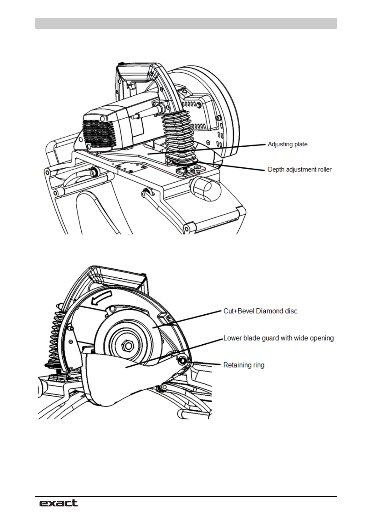
Cut+Bevel Pro Series features
Bevel depth and width is adjusted with depth
adjustment roller (Fig. B). Turning the roller
clockwise will make deeper and wider bevel and
turning the roller counterclockwise will make smaller
and thinner bevel.
Please note that the adjustment is effective only
when motor unit is locked in down position. This
adjustment is recommended to do before starting
the cutting.
When using the machine on a new pipe size, adjust
the cutting depth higher than needed prior to cutting.
It is easier to make the cut deeper than lower by
adjusting the depth adjustment roller when motor
unit is in locked down position. Correct depth setting
is confirmed with visual evaluation of the cutting
result.
PipeCut+Bevel Pro Series machine locks to the
same depth setting if depth adjustment roller is not
moved. Therefore Cut+Bevel cuts can be made on
same size pipes without any additional adjustment.
Beveling forces will push the saw to the right. To
compensate these and achieve a straight cut, motor
unit needs to be turned left. Size of this adjustment
depends on pipe material, wall thickness and bevel
size, one good adjustment position cannot be given.
To make the adjustment:
- Loosen the two screws on the body plate
- Turn bodyplate counterclockwise
- Tighten the screws
Changing the lower blade guard
When using the Cut+Bevel Diamond disc, be sure to
use also the lower blade guard with wider opening
on the bottom. Regular lower blade guard does not
have work with Cut+Bevel Diamond disc.
Lower blade guard is changed as follows:
- Remove blade and blade flanges from the
saw if
fitted.
- Pull the lower blade guard, washer, spring
and bushings of the axle. Note the locations
of bushings and spring.
- Insert bushings to the lower blade guard to
be installed
- Insert the lower blade guard with bushings,
washer and spring on the axle. Be sure to
locate the spring correctly.
- Test the correct function of the lower blade
guard, it will return to low position when
released and that it can move without any
restriction.
- Remove the retaining ring from the axle
(right and Fig A2).
Before operation the tool
- For Cut+Bevel function, ensure that Cut+Bevel
Diamond disc is installed to the saw.
Page 14

Operation
English
14
- Make sure that lower blade guard is installed with
the Cut+Bevel Diamond disc. Regular blade
cover does not have big enough opening for the
Cut+Bevel Diamond disc.
WARNING: Regular lower blade cover must
be installed if saw is used with regular saw blade
with cutting teeth.
- Ensure that motor unit is in the upright position.
- Check that the disc is correctly fitted, in good
condition and suitable for the material to be cut.
- Ensure the pipe saw guide wheels rotate.
- Ensure the support wheels rotate.
- Check the operation of the lower blade guard.
- Ensure the pipe is empty.
FIGURE B1
Connection to the mains power supply
Ensure that the mains voltage is the same as
indicated on the rating plate (Fig A / 13). Connect
the pipe saw to the power outlet only after having
checked the above points first.
Setting the pipe on supports
Use the system supports when cutting pipes. This
will ensure safe working and optimum results. Work
on flat surface. Place the pipe on two supports so
that the cutting point is between the supports. Place
two more support under both ends of the pipe.
Check that all support wheels contact the pipe
(adjust if required e.g. with pieces of lumber) (Fig
B1). When cutting short and light weight pipes, place
the supports so that the cutting point is outside
supports (Fig B2). Support the pipe with your left leg,
if required. Proper arrangements will prevent the
blade from jamming as the pipe is cut through.
Attaching the pipe saw to the pipe
Open the pipe saw's gripper unit enough to suit the
diameter of the pipe by rotating the adjustment
handle located at the rear of the saw (Fig C / 1). If
you are using laser pointer for position, Cut+Bevel
Diamond disc 165 will cut the pipe 15mm to the right
of the laser line. Fasten the pipe saw to the pipe by
turning the gripper adjustment handle until the
gripper grips firmly the pipe to be cut (Fig C / 2).
FIGURE B2
FIGURE C
Lock the mechanism by turning the gripper safety
(Fig C / 3). Hold the pipe in place and ensure that
pipe saw moves freely in the direction the pipe is
fed. For sake of safety ensure the pipe saw leads
are to the left of the pipe saw. The pipe saw is now
ready for cutting.
Page 15

Operation
English
15
Piercing the pipe wall
Grip the gripper firmly with your right hand and place
your left foot on top of the pipe approximately 50 cm
from the pipe saw. Turn the saw until it leans slightly
forward (Figure F). When starting the motor, first of all
release the power-switch locking lever (Fig D/1) and
push the power switch all the way down (Fig D/2).
Before starting to saw, wait until the blade reaches full
speed. Pierce the pipe wall by pressing pipe saw
operating handle downwards slowly and evenly until
the blade has cut through the pipe wall (at this stage
the pipe must not rotate) and the motor unit is locked in
the sawing position (Fig F / 1).
Look at the UNLOCK SWITCH during the piercing
operation. When UNLOCK SWITCH is locked, i.e. the
yellow mark disappears (Fig E / 1-2),the pipe saw is
locked in the sawing position, and you can safely start
sawing around the pipe.
Adjust bevel depth as needed with depth adjustment
roller.
Cutting around the pipe
Start cutting by feeding the pipe saw forward and fix
the pipe with your left foot (Fig F / 2). After that release
the pipe (remove your left foot from the pipe) and turn
the pipe saw backwards, whereby the pipe will also be
rotated backwards (Fig G). Start a new feeding
movement, and feed continuously forward ca. 1/6 of
the pipe's circumference (Fig H). Repeat until the pipe
is cut off. Select the feeding speed as per the material
and the thickness of the wall. Too high speed can
damage the blade, overload the pipe saw and give a
poor cutting result.
When the pipe is cut off, push the UNLOCK SWITCH
forward until the yellow mark is visible and the locking
is released (Fig I / 1). Now raise the motor unit to
starting position (Fig I / 2). Release the power switch
(Fig I / 3). When the blade has stopped, open the
gripper safety mechanism (Fig I / 4) and disengage the
pipe saw from the pipe by loosening the gripper
adjustment handle (Fig I / 5). Ensure that the moving
lower blade-guard is lowered into safety position.
Should there be problems during piercing or cutting,
abnormal sounds or vibrations and you have to
interrupt cutting before the pipe is cut through, release
the motor unit locking by pushing the UNLOCK
SWITCH forward until the UNLOCK SWITCH is
released and lift the motor unit up. Once the problem is
cleared, start sawing again.
Never start the motor, when the motor unit is locked in
sawing the position or teeth of the blade contact the
pipe to be sawn. Ensure, that the blade/disc is not
connected to pipe during the motor operating.
FIGURE D
FIGURE E
FIGURE F
FIGURE G
Page 16

Operation
English
16
Normal operation
Normal power output
Green: ON
Red: OFF
Motor temperature high
Normal power output
Green: OFF
Red: OFF
Motor current high WARNING
Decreasing power output
Green: OFF
Red: OFF
Motor temperature
cooling with free running
Green: OFF
Temperature sensor faulty
the work
Green: OFF
Red: OFF
End of the cut
Start of the cut
End of the cut
Start of the cut
Overload protector and blade RPM speed control
The saw has a two-speed blade RPM speed control
(Fig A / 15). When cutting stainless or acid-proof
steel use the lower RPM setting l. When cutting
other materials use the faster RPM setting ll.
The saw also has an overload protector which
displays electric motor loading with three indicator
lights (Fig A / 5).
Explanation of indicator lights (FIGURE J)
FIGURE H
WARNING
protection active
Power output very low, only
Power output low to finish
Yellow: OFF
Yellow: Blinking
Yellow: Blinking
Yellow: OFF
Red: Blinking
Yellow: ON
GREEN If green light is on, the motor temperature
and power output are normal.
You can continue using the tool.
YELLOW If yellow light begins to flash, the motor is
hot and/or overloaded.
You should slow down the cutting
speed (It is possible, that you are using a
worn-out blade)
RED If the red light begins to flash, motor
power is automatically reduced to the
minimum to protect the motor. Cutting is
not possible.
Press the motor switch and let it run
freely (UNDER NO LOAD) until the
green light is on.
ATTENTION!
If the yellow light turns on when saw
is powered, it indicates that the motor control unit
has been damaged. You can finish the sawing, but
the saw should take out for service. If the motor
control unit is not repaired, the motor of the saw will
get damaged.
Improving possible misalignment of the cut
The cut is affected by many factors, e.g. the size of
the pipe, the material, the wall thickness, the quality
of the pipe's surface, the roundness, welded seams,
blade condition, feed rate, operator's experience.
For this reason, the saw may move to left or right
cussing unperfect cut (see Fig K).
FIGURE I
FIGURE J
GO AHEAD
WARNING
RUN THE MOTOR UNTIL
GREEN LIGHT IS ON
FIGURE K
Saw has moved from right to left
Page 17

Operation
English
17
Saw has moved from left to right
Page 18

Operation
English
18
Rotate wheel to
make
Rotate wheel to
make
Cutting result adjustment for models Exact PipeCut+Bevel 280 / 360 / 460 Pro Series
Within the gripping devices of these models there are
eight control wheels. One of them is the adjustment
wheel (FIGURE A / 9). Please note that adjustment by
this wheel concerns only the size of one pipe and
material and the wheel may need to be adjusted again
as the saw blade or disc wears out.
Adjust the wheel by releasing the locking screw
(FIGURE L / 1) and turning the central part of the wheel
CLOCKWISE or ANTICLOCKWISE to obtain the
desired position (FIGURE L / 2), lock the wheel again
(FIGURE L/3).
If the saw is moving from right to left (FIGURE K/a),
turn the central part of the adjustment wheel so that "d"
is smaller (FIGURE K/a). If the cutting is carried out
according to Figure K/b, proceed as shown in Fig. K/b.
It is recommended to lubricate the adjusting wheel
periodically.
In these models the angle of the entire engine can be
adjusted left or right. The laser beam can be used to
aid in correct adjustment.
Adjustment stages
1. Mark the reference line precisely on the pipe at an
angle of 90 degrees in the longitudinal direction.
2. Place the saw on the pipe so that the red line of the
laser is next to the reference line at an angle of 90
degrees. Tighten the griper to the normal tension level.
Check if the laser line and reference line are parallel. In
FIGURE M/A the laser beam is not parallel with the
reference line.
3. Release the two locking screws of the adjustment
plate (FIGURE M/b 1 and 2).
4. Adjust the motor unit to the left or right as needed to
get the laser beam and the reference line parallel. In
FIGURE M/c the laser beam is parallel with the
reference line.
5. Tighten the locking screws of the adjustment plate
very tightly.
CAUTION! The adjustment indicator located in the back
of the adjustment plate does give the exact
measurement to adjust. The indicator shows only the
direction of adjustment and the category of magnitude.
FIGURE L
d smaller
d bigger
FIGURE M /a
FIGURE M /b
FIGURE M /c
Page 19

Operation
English
19
CAUTION! If the motor unit is adjusted with the laser, the
gripping device must be attached to the pipe with
normal tension. This ensures that the saw fastening
corresponds to the normal condition of operation.
If you are not satisfied with the cutting result of your
saw and you need to adjust it again then always start
by adjusting the eccentric adjustment wheel.
Maintenance and servicing instructions
Remove the power plug from the socket before
servicing or cleaning the pipe saw. All maintenance
operations carried out on the pipe saw's electrical
components must be carried out by an approved
service center or engineer.
Blade
Installing and changing the saw blade
WARNING: To reduce the risk of injury, turn the
unit off and disconnect it from the power source before
installing and removing accessories, before adjusting
or when making repairs. An accidental start-up can
cause injury.
Remove the power plug from the socket.
Remove the blade guard cover (Fig N / 1) by opening
the blade guard screw (Fig N / 2). Press the spindlelock button (Fig A / 12) and simultaneously rotate the
blade by hand until the spindle-lock button drops a
further distance of about 7 mm. Now the rotation of the
blade is prevented. Use the blade key to open the
blade attachment nut. Remove the securing nut (Fig N /
3), the outer blade flange (Fig N / 4) and the blade
(Fig N / 5).
Before installing a new blade, check that both blade
flanges are clean. Place a new or sharpened blade on
the back flange (Fig N / 6), so that the marked side of
the blade is facing outwards and the arrows on the
blade are facing in the same direction as the rotation
direction markings on the inside of the blade cover.
Ensure that the new blade goes right to the bottom on
the back blade flange. Put the outer blade flange, and
the securing bolt back in place. Press the spindle lock
button and tighten the blade securing nut. Put the blade
guard cover back in place and tighten the blade cover
bolt.
When changing to Cut+Bevel Diamond disc, change
also the lower blade cover to version with wide opening
according to instructions on page 12.
WARNING: Regular lower blade cover must be
installed if saw is used with regular saw blade with
cutting teeth.
FIGURE
N
Check the condition of the blade. Replace a bent, blunt,
or otherwise damaged blade with a new one. Using a
blunt blade can overload the pipe saw's electric motor
and gearbox. When you notice that the blade is blunt
do not continue cutting with it, as the blade may
become so badly damaged that it will not be worth
sharpening. A blade in sufficiently good condition can
be sharpened a few times by a professional sharpening
company. Diamond X Discs cannot be sharpened
Gripper unit
Clean the gripper unit regularly with compressed air.
Lubricate the gripper's wheel axles (Fig O / 1 and 3)
and its joints (Fig O / 2). Clean and lubricate also the
gripper's trapezoidal screw and the two adjusting nuts
on it (Fig O / 4).
Blade guard
When you have cut plastic pipes and then intend to
start cutting metal pipes always clean the inside of the
blade guards. Hot metal particles originating from metal
cutting will heat up plastic particles, which may release
toxic smoke. Make it a rule to clean the blade guard
regularly and pay special attention to keep the moving
blade guard movement from becoming obstructed.
Lubricate the axis of the moving blade guard regularly.
As an extra equipment you can buy outer blade
guard with connection for vacuum cleaner. For
extra equipment see page 19.
Motor
Keep motor air vents clean to allow free airflow.
FIGURE O
Page 20

Environment, Guarantee, Tips
English
20
Plastic parts
Clean the plastic parts with a soft rag. Use only mild
detergents. Do not use solvents or other strong
detergents as they may damage the plastic parts and
painted surfaces
Power cable
Check the condition of the power cable regularly. A
faulty power cable should always be replaced at an
approved service center. Correct use and regular
servicing and cleaning will ensure the reliable operation
of the pipe saw.
CAUTION!
The following items or services are excluded for
Warranty claims:
- Saw blades
- Carbon brushes
- Blade or attachment flange
- Blade attachment nut
- Normal wear
- Failures caused by misuse or accident
- Water, fire or physical damage
- Cables
- Adjustment of eccentric adjustment wheel
- If a wrong type of generator has been used as
power source.
Environment
Separate collection. This product must not be disposed
with normal household waste. When your Exact
PipeCut machine is worn out, do not
dispose it with normal household waste. This product
must be recycled separately. Separate recycling of
used products and packaging support recycling and
recovery of materials. Reusing recycled materials helps
preventing the pollution of the environment. According
to local regulations it is possible to deliver household
appliances to municipal rubbish depositories or to the
dealer when purchasing a new product.
Guarantee
Warranty terms valid from 01.01.2018.
If the Exact PipeCut saw becomes unusable due to
material or manufacturing defects within the Warranty
Term, at our discretion we will repair the Exact PipeCut
Saw or supply an entirely new or factory reconditioned
Exact PipeCut Saw at no charge.
The Exact Tools Warranty Term is for 12 months from
date of purchase.
The Warranty is only valid if:
1.) Copy of a dated purchase receipt is returned to the
Authorized Warranty Repair Center or has been
uploaded to our website at the time of warranty
registration.
2.) The Exact PipeCut Saw has not been misused.
3.) No attempt has been made by non-approved
persons to repair the saw.
4.) The Exact PipeCut Saw has been used in
accordance with the operating, safety, and servicing
instructions provide in these instructions.
5.) The Exact PipeCut Saw has been delivered to an
Authorized Warranty Repair Center within the
warranty period.
Exact Pipe Cut operation tips
Diamond blades can only be used for cutting cast or
ductile iron pipes. This pipe material is not
recommended to cut using to a blade of any other type
Clean the inside of the blade guards after cutting
plastic pipes.
Smaller pipes are easier to cut by turning the pipe
manually either on the table or on the floor.
CAUTION! Turn the pipe towards yourself when you do
it manually. Don't turn the pipe too fast.
Check the condition of the blade regularly.
The cutting process is divided into two stages: first you
need to cut through the pipe wall and then cut around
the pipe.
Do not overload the saw while working without
interruption. The pipecut will overheat and metal parts
can become very hot. In this case, the motor and blade
may become damaged. Use the pipecut system in
accordance with its duty cycle being continuous cutting
2.5 minutes, then let it cool under no load for 7.5
minutes.
Maintain a uniform feed rate. This increases the
lifespan of the blade. For example, a steel pipe with
an outer diameter of 170 mm (6') and wall thickness
of 5 mm (1/5'), the cutting time-is15-20 seconds.
Accordingly cast iron pipe with an outer diameter of
4' (110 mm) and wall thickness of 1/6' (4 mm), the
cutting time is 20 – 25 seconds.
When not cutting, keep the motor unit in the up
position. Never please the tool on the pipe with
motor unit in locked down / cutting position.
NOTICE! The Exact PipeCut Saw is to be shipped to
the Authorized Warranty Repair Center freight
prepaid. If the Exact PipeCut Saw is repaired under
Warranty, the return shipment will be made freight
prepaid.
Page 21

Extra equipment, cutting depths
English
21
Factors influencing blade lifespan:
Pipe material
Blade suitability for the pipe material
Correct motor speed setting
Pipe wall thickness
Feed rate
Smoothness of the pipe
General user knowledge
Cleanliness of the pipe
Corrosion on pipe
Weld seam on the pipe
Blade speed
Factors influencing straightness of cutting:
Blade condition
Pipe wall thickness
Feed rate
Smoothness of feed
General user knowledge
Cleanliness of the pipe
Pipe circumference
Too loose or tight gripping device
Too tight blade
Extra equipment 280 – 360 – 460 PS
Protection cover with vacuum cleaner connection for
plastic cutting.
FIGURE P
Due to continuous product development, the present manual may be modified. No changes will be reported
separately.
For more information check www.exacttools.com
Blade suitability
Exact TCT: Suitable for cutting steel and all kinds of
plastic pipe material
Exact Cermet: Suitable for cutting stainless steel
and acid proof materials, steel, copper, aluminum
and all kind of plastic pipe materials.
Exact ALU: Suitable for cutting aluminum and all
kinds of plastic.
Exact Diamond: Suitable only for cutting cast and
ductile iron pipe materials, also for concrete lined
cast iron pipes.
Exact TCT 140
Exact Cermet 140
Exact ALU 140
Exact Diamond X 140
Exact TCT 165
Exact Cermet 165
Exact ALU165
Exact Diamond X 165
Exact Cermet 180
Exact ALU 180
Exact Diamond X 180
Exact Plastic 190
Exact Cut+Bevel Diamond disc 140
Exact Cut+Bevel Diamond disc 165
Page 22

Pipe Cutting System
Exact Tools Oy
www.exacttools.com
Steel pipes
Max.pipe wall thickness 20 mm / 0.78”
Stainless steel pipes
Max.pipe wall thickness 20 mm / 0.78”
Cast or ductile iron pipes
Max.pipe wall thickness 20 mm / 0.78”
Any on plastic, aluminum, cooper
Pipe wall thickness of these pipes is not limited
Max.pipe wall thickness 12 mm / 0.47”
Stainless steel pipes
Max.pipe wall thickness 12 mm / 0.47”
Cast or ductile Iron pipes
Max.pipe wall thickness 12 mm / 0.47”
Any types of plastic, aluminum, copper
Pipe wall thickness of these pipes is not limited
50 5,3 17,8 25,3
30,3 75 4,9 17,4 24,9
29,9
110 6,8 19,3 26,9
31,9 115 7,2 19,8 27,2
32,2 140 9,5 22,0 29,5
34,5 165
12,0 24,5 32,0
37,0
215
17,2 29,8 37,2
42,2
270
22,6 35,1 42,6
47,6
320
_ _ _
_
_ _ _
_
50
_ _ _
_
75
21,6 34,1 41,6
46,6
110
15,6 28,4 35,6
40,6 115
15,3 27,8 35,3
40,3 140
14,9 27,4 35,0
40,0 165
15,5 28,0 35,5
40,5
215
18,0 30,5 38,0
43,0
270
21,6 34,1 41,6
46,6
320
24,9 37,4 44,9
49,9
Theoretical maximum cutting depths
280 PS
with blade diameters 140, 165, 180, 190
OD/mm 140
100
355
Max. Pipe wall / mm,
165
6,1
18,6 26,1 31,1
180 190
360 PS
Max. Pipe wall / mm,
with blade diameters 140, 165, 180, 190
OD/mm 140
100
355
16,4
26,7
165
180 190
28,9 36,4 41,4
39,2 46,7 51,7
Max. pipe wall thicknesses in different pipe materials, which can be cut by
Exact PipeCut+Bevel 280 / 360 / 460 Pro Series machines
European model 230V / 2500W
USA model 120V / 15A
Steel pipes
ATTENTION!
ATTENTION!
Do not cut pipes with thicker than the above mentioned wall thickness.
Check the status and condition of the blade before cutting
Särkinimentie 5 B 64
00210 HELSINKI
FINLAND
Tel. + 358 9 4366750
Fax + 358 9 43667550
exact@exacttools.com
 Loading...