

EWS ES 2050, ES 2051 Instruction Manual

Electronic Controllers for water softening units
Instruction Manual
ES 2050
ES 2051
Software version 4.01

CONTENTS
System Description ............................................. .... ... ........ .... ... .... .... .... .... ... .... ........ ... .... ........................ 1
Wall mounted ES 2050, Panel mounted ES 2051 ............................... ...................... ....................... ..... 2
Status and Regenerationmessages ..................................................... .......................................... ........ 3
LED-display ....................................................................................................................................... 3
LED - control lamps .................................................................................... .... .... .... ... ........................ 3
LCD - display ..................................................................................................................................... 3
Service status ................................................................................................................... ............ 3
Regeneration status .................................................................................................................... . 4
Changing and indication of programme values ...................................................................................... 5
Hardness of the water supply ............................................................................................................ 5
Current Time ...................................................................................................................................... 6
Information DISPLAYS ...................................................................................................................... 6
Flush period .................................................................................................................................. 6
Regeneration time ........................................................................................................................ 6
Additional program ....................................................................................................................... 7
Unit capacity ........................................................................................................................ ......... 7
Treated water produced ............................................................................................................... 7
Inputs ............................................................................................................................................ 8
Outputs .................................................................................................................................... ..... 8
Service - Telephone number ........................................................................................................ 8
Maintenance ........................................................................................................................ ......... 8
Software version .......................................................................................................................... . 8
Alarms / warnings .. ... .... .... .... ... .... ........ ... .... .... .... .... ... .... .... ........ ... .... .... .... ... .... .... .... ....... ........................ 9
Programmed capacity exceeded ....................................................................................................... 9
Electrical supply failure ............................................................................................................. ....... 10
Refill chemical tank .. .......................... ........................... .......................... ........................... .............. 10
Await regeneration ........................................................ .......................... ........................... .............. 11
Pre contact (regeneration pre initiation warning) .................... ........................................................ 11
Minimum inter regeneration time limit .................................. ... .... .... .... ... .... .... .... ... .... ........ .... ... ....... 12
Minimum/maximum programmed value exceeded ......................................................................... 12
Message: Maintenance ................................................................................................................... 12
Manual regeneration initiation ............................................... .............................. ...................... ........... 13
Remote control ..................................................................................................................................... 14
"water meter" Signal input ............................................................................................................... 14
"chemicals low" Signal input ..................................... .... .... ....... .... .... .... ... .... .... .... .... ... .... ....... . .......... 14
"await " Signal input ......................................................................................................................... 14
"start" Signal input ................................................ ........................................................................... 15
"duty changeover without regeneration" Signal input ......................................... .......................... ... 15

Special functions................................................................................................................................... 16
Duty changeover without regeneration .................................................. ............ ........... ........... ..... .. 16
Regeneration of the standby unit .................................................................................................... 16
Regeneration stop ............................................................................................................................ 16
Fast program facility .............................................................................................................. .......... 17
Flush ON/OFF ................................................................................................................................. 17
Regeneration without counter Reset .................................................................. ............................. 17
Setting and changing of initial values ................................................................................................... 18
1. Duty changeover ................................................................................................................. ....... 19
2. Pre service regeneration ............................................................................................................ 19
3. Prohibited regeneration period ................................................................................................... 20
Start on real time clock ......................................................................................... ...................... 21
4. Time controlled regeneration ..................................................................................................... 22
5. Minimum time between regeneration’s ...................................................................................... 23
6. Water meter ................................................................................................................................ 24
7. Flow-pulse .................................................................................................................................. 24
8. Incoming water supply hardness ............................................ ........................... ......................... 25
9. Exchange capacity ....................... .... .... .... .... ... .... .... ....... .... .... .... .... ... .... .... .... .... ....... .... . ... .......... 26
10. Pre regeneration signalling ........................................................................................................ 27
11. Number of valve switching pulses ........................................................................ .... .... ... .... .... ... 28
12. Electrical control ...................................................................................................................... ... 28
13.Pulse timing ................................................................................................................................ 30
14. Regeneration times .................................................................................................................... 31
15. Additional programme
(Regeneration-additional programme, flushing, high pressure pump) ...................................... 32
16. Alarm and warning relay outputs ................................................................................................ 35
Capacity exceeded ..................... .......................... ........................... .......................... ....... 35
Power supply failure ......................................................................................................... 35
Refill chemical tank .......................................................................................................... 36
Await regeneration ........................................................................................................... 36
17. Input "WAIT" .............................................................................................................................. 36
18. “Start” input ................................ ................................................................................................. 37
19. Service ........................................................................................................................................ 37
Typical installation diagram .................................................................................................................. 38
Remote monitoring control ................................................................................................................... 38
Typical Electrical wiring diagrams ........... ............................................................................................. 39
Electrical connection details ................................................................................................................. 41
Installation recommendations and commissioning ............................................................................... 42
Technical specifications ....................... .......................... .......................... ........................... .................. 43
Declaration of conformity ........................................................................................................ .............. 44

ES 2050/51 System Description 1
System Description
The ES 2050 (wall mounted) and ES 2051 (panel mounted) controllers are designed for the monitoring
and control of simplex (single exchange column) and duplex (twin exchange columns) water softener
installations.
Whilst a simplex installation can not provide softened water to service when the exchange column is in
regeneration, a duplex installation is capable of providing treated water from one column whilst the other
is being regenerated. Duplex plants can be operated either in duty/standby mode (one unit in service,
the other either in regeneration or waiting to be called into service), or in parallel mode (both units in
service except when one is regenerating). The regeneration o f an exchange column is effected either by
one central control valve or by means of a pilot system controlling individual valves.
Regeneration is usually initiated after a measured volume of water has passed through the plant, this
volume is automatically calculated when the exchange capacity and the feed water hardness are
programmed into the controller. Alternatively the regeneration cycle may also be initiated either, after a
predetermined time period, or, by the operation of an external contact e.g. hardness monitoring
equipment, or, push button, or, based on the real time c lock. Because, particularly with simplex plants,
there can be periods of the day when regeneration would be undesirable, e.g. periods of high demand,
the control can be programmed so that regeneration cannot take place between certain times. When this
postponed regeneration facility is in use, any initiation signal is stored and a display indicates the earliest
time at which the already initiated regeneration cycle may commence.
An external contact may be used to:
a) inhibit or abort a regeneration cycle
b) open or close the service valve.
In order to prevent microbiological degradation of the unit due to prolonged periods of non operation, the
stand-by unit of a duplex water softener installation can be regenerated immediately prior to being put
into service.
A minimum time interval between successive regeneration cycles may be set, thus allowing brine
systems to recover between regeneration’s, if necessary.
Five volt free relay contacts are available for control of valves, pumps, lamps, etc. or can be used for
remote monitoring.
1. Additional programme relay (programmable):
a) available before, during or after part of the regeneration cycle.
b) can be used to open a dump valve flushing the plant to drain each time a pre-set
volume of treated water has been produced.
c) allows control of a valve or pump during the regeneration or service.
2. Regeneration relay:
Contact available during the regeneration cycle.
3. Flow pulse relay (programmable):
a) repeats the contact of the water meter for remote monitoring of water use.
b) used to control the fill valve of the chemical tank.
4. Warning relay:
Programmable warning contact.
5. Alarm relay:
Programmable fault contact.
ES 2050/51 Wall mounted ES 2050 2
Panel mounted ES 2051
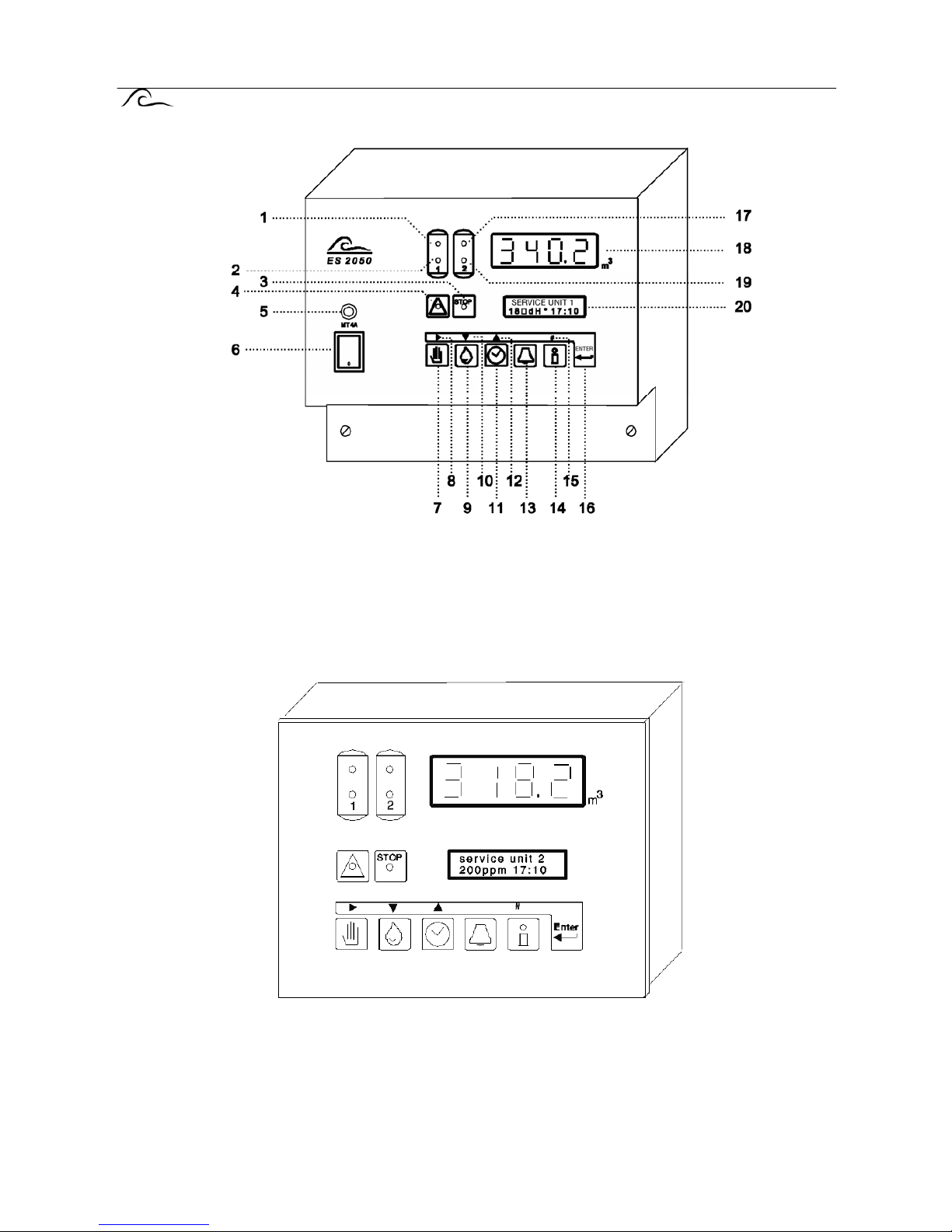
Wall mounted ES 2050
1 Service unit 1 8 Position cursor 15 Numerical input
2 Regeneration unit1 9 Supply water hardness 16 Programming
3 Alarms 10 Next program 17 service unit 2
4 Warnings 11 Real Time 18 LED Display
5 Fuse 12 Previous program 19 Regeneration unit 2
6 Main switch 13 Unlock 20 LCD display
7 Regeneration start 14 Information
Panel mounted ES 2051
ES 2050/51 Status and regeneration messages 3
Status and Regeneration messages
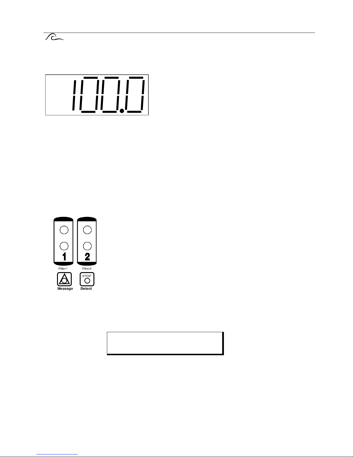
LED - display.
m³
Whilst a unit is in service the LED - display indicates the remaining volume of water which can be
softened before the next regeneration will be required.
When operating without a water meter, i.e. in time control, the display usually shows the full capacity
between regeneration’s.
During the regeneration of a simplex plant the display will read " 0 m
3
".
If the maximum value of 9999 is exceeded the LED display will show the text "OFL" as long as the value
is to high.
NB! There is an additional "decimal point" in the bottom right hand corne r of the display. This flashes
when flushing has been commenced (see step 15 in the basic programme.
LED - control lamps
Coloured lamps are used to give the most important status indications.:Unit 1 in service (green)
Unit2 in service (green)
Unit 1 in regeneration (yellow)
Unit 2 in regeneration (yellow)
Message (red)
Fault (red)
Additional information is provided by the LCD display
LCD - display.
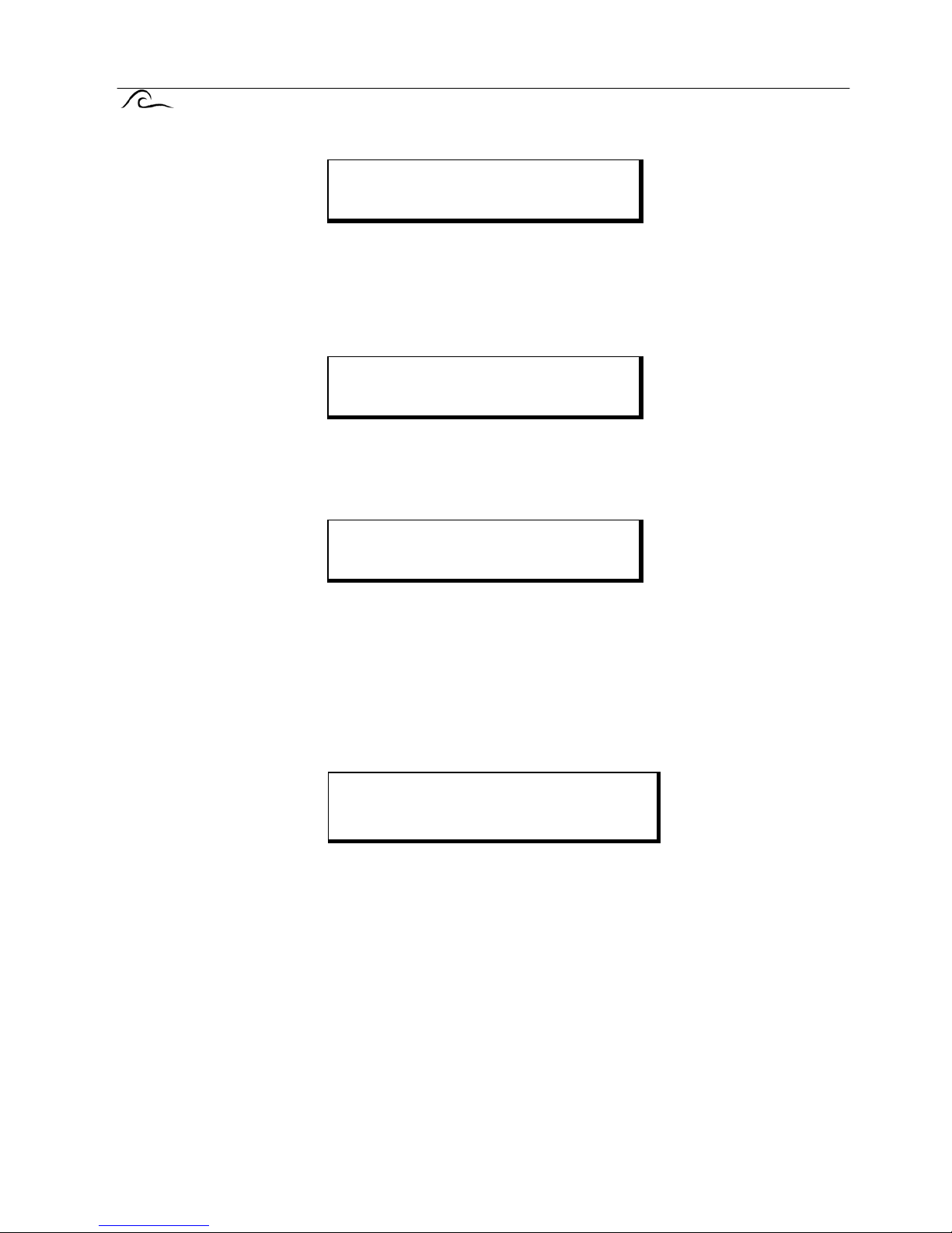
Service status.
The first line of the LCD display indicates the actual condition of the plant, e.g. unit 1 in service.
Usually during the service cycle the following information is given by the second line of the LCD:
The left hand part of the line shows the incoming water hardness which has been programmed
into the unit.
The current time is displayed on the right.
Service unit 1
200mg/l 17:00
ES 2050/51 Status and regeneration messages 4
However some operating regimes will produce alternative messages :Either:
When operating with the control set to prohibit regeneration between certain times (section 3 of the
programming instructions), if regeneration is required it will be postponed and the initiation signal
stored until the end of the prohibited period, the second line of the display will show the time at
which the unit will commence regeneration and the current time.
or:
If the control has been set to initiate a regeneration after a fixed time interval the second line of the
display will show the number of hours remaining until regeneration will take place and the current
time.
or:
The control can be programmed to give a signal, e.g. for a bleed valve, each time a predetermined
volume of water has been supplied. When this output is active the second line of the display shows
the remaining signal duration.
Regeneration status.
The first line of the LCD display indicates the actual condition of the plant, e.g. unit 1 in regeneration.
The second line of the LCD display shows, the regeneration step or phase in progress, the time
remaining in the step and indicates, when an additional routine has been selected (section 15 of the
programming instructions), whether the output is active. "-" indicates active "l" indicates inactive. If
"Step: 0" is displayed it means that the additional routine will operate before regeneration can
commence, similarly "Step: 6" indicates that the additional routine is continuing beyond the end of the
regeneration cycle. If required the duration and remainder of the additional routine can be displayed
briefly by pressing the INFO key (see page 6).
Service unit 1
Reg18:00 17:00
Service unit 1
Reg 72h 17:00
Service unit 1
Flush-time 20s
Regen. unit 1
Phase : 2 15 Min.-
ES 2050/51 Changing and indication of program values 5
Changing and indication
of programme values.
The most important programme values can be recalled and, changed if required, by pressing a key.
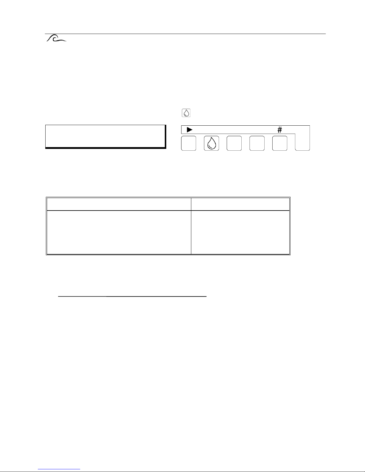
Hardness of the water supply.
Press the "Hardness" key, indicated by the symbol , to display the supply water hardness.
Should it be necessary to change the programmed value; the arrow key "8" may be used to move the
flashing cursor to the digit to be changed, and the Number key "#" to make the change.
A desired unit of hardness measurement may be selected (section 8 of the programming instruct ions),
the following are available :-
Hardness units Programmable range
°D
°F
°E
mg/l CaCO
3
gpg
German hardness degrees
French hardness degrees
English hardness degrees
Milligrams per litre as CaCO
3
Grains per gallon
2 - 99
4 - 199
2 - 99
40 - 1990
2 - 99
The controller automatically recalculates the capacity between regeneration’s us ing the new value, at the
initiation of the next regeneration cycle, as follows :-
If the resulting value exceeds the maximum value of the LED display (9999 m3) "maximum value
exceeded" will appear in the display.
Important Note! If a hard water blending by pass is used so that the water meter indicates the blended
water capacity, it is essential to subtract the final, blended, water hardness from the value to be inserted.
Example:
supply water hardness = 300 mg/l CaCO
3
, blended water hardness = 120 mg/l CaCO
3
Thus a value of 180 mg/l CaCO3 (300 mg/l CaCO3 - 120 mg/l CaCO3) must be programmed into the
control.
Water hardness:
220mg/l
Column capacity [ grms CaCO3 /m3 of resin x m3 of resin]
=Softened Water Capacity [m
3
]
Supply Water Hardness [mg/l ~ CaCO
3
]
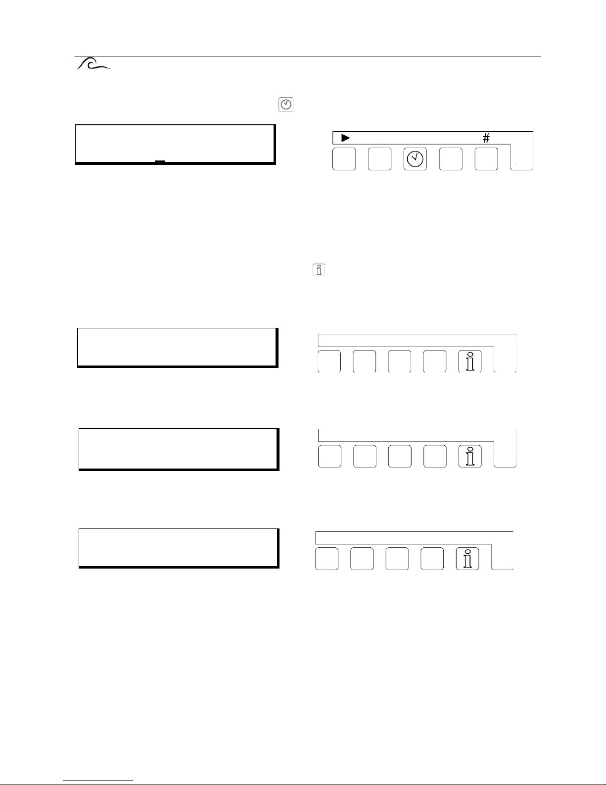
ES 2050/51 Changing and indication of program values 6
Current Time.
Press the "Time" key indicated by the symbol , to display the current time.
Should it be necessary to change the programmed value; the arrow key "8" may be used to move the
flashing cursor to the digit to be changed, and the Number key "#" to make the change.
Information DISPLAYS.
The "INFORMATION" key makes it possible to retrieve information, e.g. values from memory. Each time
the "INFORMATION" key indicated by the symbol
, is pressed a different piece of information is
displayed :-
Flush period.
The programmed volume between successive flush signals, the volume remaining to the next flush
signal and the duration of the flush signal are displayed.
Regeneration time .
The duration of a complete regeneration cycle and the possible additional time which could be
programmed in are displayed.
Regeneration restrictions.
NoReg 16:00-18:00 if the control has been set to prohibit regeneration between certain times (section 3
of the programming instructions), this part of the display shows the time between which regeneration is
prohibited. Otherwise the display will read : NoReg---.
Current Time
Mo 16:48
Flushing
500l 350l 20s
Regen.time [min]
Σ 125 rest 15
NoReg16:00-18:00
IntRg72 MinRg4
ES 2050/51 Changing and indication of program values 7
IntRg 72 if the control has been set to initiate regeneration after a programmed time interval (section 4 of
the programming instructions), this part of the display shows programmed time interval in hours.
Otherwise the display will read : IntRg -.
MinRg 4 if the control has been set to give a minimum period between successive regeneration’s
(section 5 of the programming instructions), this part of the display shows the programmed time interval
in hours.
Otherwise the display will read : MinRg -.
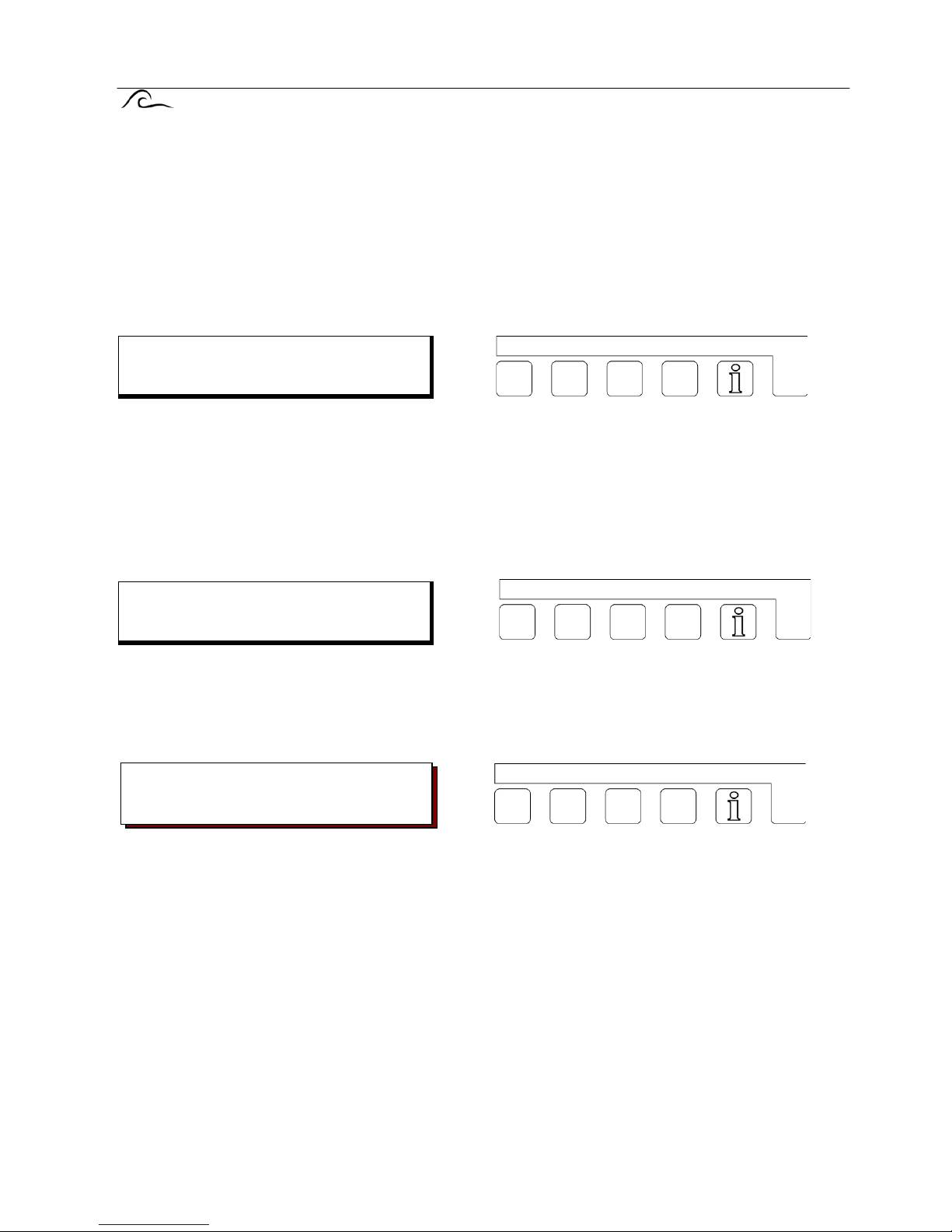
Additional program.
If the additional program has been selected (section 15 of the programming instruc tions), the selected
start time and the duration of the additional program are displayed, if "Step 0" is displayed the additional
routine will operate before regeneration can commence, similarly "Step: E" indicates that the additional
routine will continue beyond the end of the regeneration cycle. If the program is activated the display
shows how long it has left to run.
If no additional program in has been entered "No additional program" will appear in the display.
Unit capacity.
The calculated capacity between regeneration’s is displayed.
Treated water produced.
The total volume of water which has been treated by the plant.
Warning: This counter can be reset to zero by a service engineer, consult service logs for details of
the value prior to reset.
Additional progr.
Step:2 26 Min.
Unit capacity
150 m3
Treated water
45367 m3

ES 2050/51 Changing and indication of program values 8
Inputs.
Indicates the current status of each input, the inputs are :WM = water meter RC = regeneration chemicals WA = wait RS = regeneration start
Inputs WM, WA, and RS are shown as active when the external contacts are closed, RC is active
when the external contact is open. Active states are indicated by "1" after the input reference,
inactive by "0".
Outputs.
Indicates the current status of each output, " l " below an output number indicates an ac tive output," - "
an inactive one.
Service - Telephone number.
To change the telephone number.
Select the digit using the "8" key, the number can then be changed by using either the "6" or "t" key.
Maintenance.
If the automatic maintenance required warning is programmed the pre set maintenance interval is
displayed on left hand side of the second line and the quantity of treated water produced since the last
maintenance visit is displayed on the right hand side of the second line.
Software version
The software is regularly updated in the factory.
Modifications are made in order to adapt the product in accordance technological changes and
customer requests. The display indicates which version of the software is loaded.
Input
WM0 RC0 WA0 RS0
Out123456789AB
|----------
Service
0031 73 443755
Maintenance
500m3 20m3
Software-version
ES2050 9606-2.20
ES 2050/51 Alarms / warnings 9
Alarms / warnings.
When the equipment is operating, various messages may appear in the display, this facility can be used
to drive relay outputs or to give alarms or warnings. The relay positions are indicated by red control
lamps bearing symbols for "Attention" for messages and "Stop" for alarms. The progra mming of these
functions is described in sections 5, 10,15 and 18 of the programming instructions.
Descriptive text appears in the LCD display, in addition to the fault or warning light indication.
Programmed capacity exceeded.
This message can only be displayed when controlling a duplex plant and appears if the working unit
requires regeneration whilst the off line unit is in regeneration.
Possible causes when the plant is water meter controlled:
Wrongly programmed capacity.
Wrongly programmed incoming hardness.
The water meter is faulty or of the incorrect type.
Excessive demand for water e.g.. a large tank being filled very rapidly.
Possible causes when regeneration is remotely initiated by water analysis equipment signal:
Faulty analytical equipment.
Incorrect operation of analysis unit.
Water analysis equipment too sensitive or giving spurious readings.
Inadequate regeneration of the unit leading to shortfall in capacity.
IMPORTANT! In this condition if regeneration initiation is volume dependent, i.e.. by water meter, the
on-line unit will begin to regenerate as soon as the other unit has finished it's regeneration.
If a salt saturator is being used and there is insufficient brine available for the second regeneration the
second regeneration cycle must be prevented either by switching off the control or by giving a "wait"
input. Once sufficient brine is available the second unit can be allowed to regenerate.
Press the "UNLOCK" key indicated by the symbol
, in order to reset the warning or alarm relay. If the
key is pressed a second time, the LCD display will also be reset, providing that the initiation signal is
also no longer present. Then the regeneration of the second unit will not take place.
Installation
exceeded

ES 2050/51 Alarms / warnings 10
Electrical supply failure.
If there is a failure of the power supply no status information will be lost. The control panel "remembers"
the condition it was in when the supply is interrupted.
NB. The current time will be lost and must be re-entered.
IMPORTANT! If the plant is in a regeneration cycle when the power supply fails it is possible for the unit
to become partially exhausted, by the passage of water to drain, if the water supply is maintained during
the power failure.
In this situation the regeneration cycle should be terminated and a new cycle initiated first ensuring
sufficient chemicals are available.
Press the "UNLOCK" key indicated by the symbol
, in order to reset the warning or alarm relay and
then reset the current time.
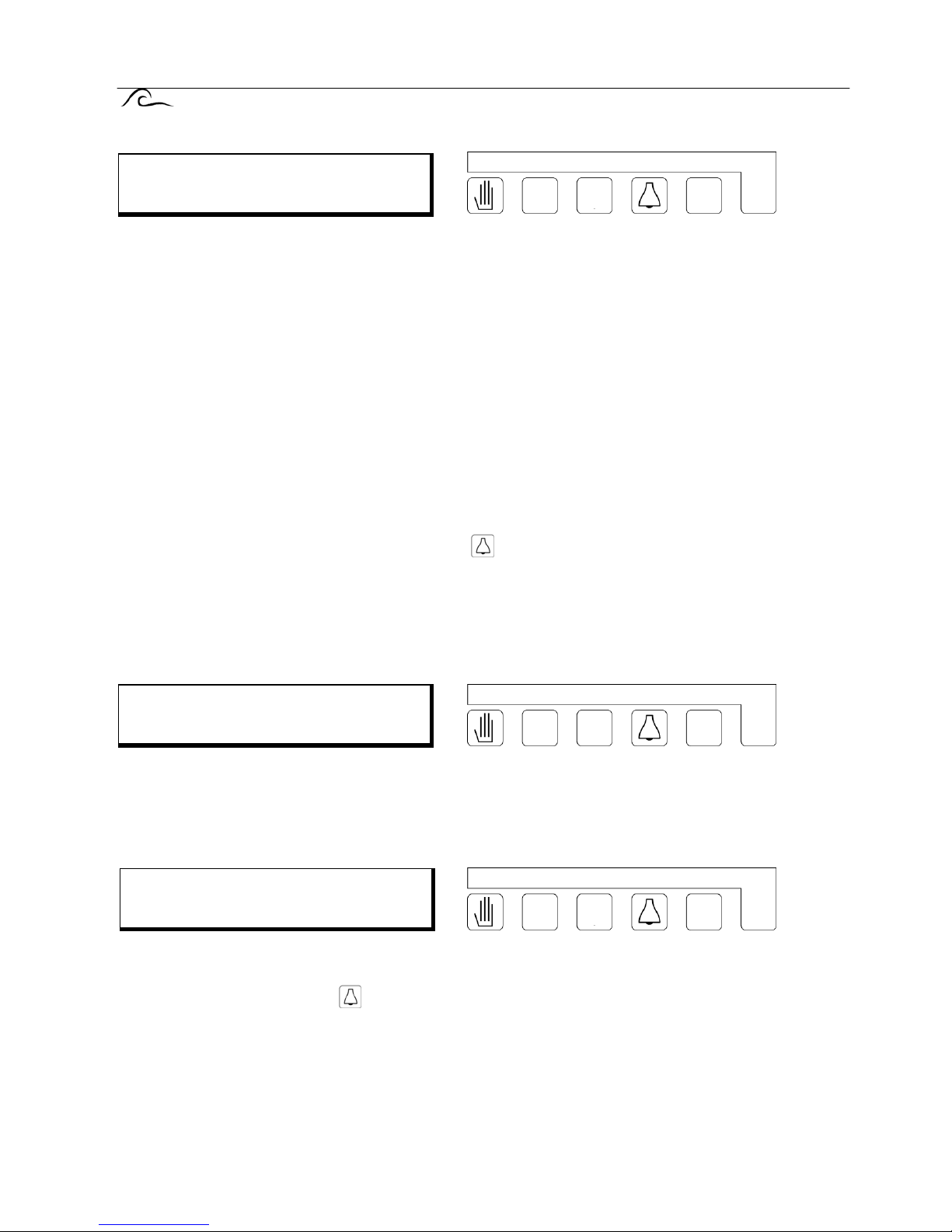
Refill chemical tank.
NOTE: This message can only appear only if there is a "regeneration chemicals" input co nnected.
Chemicals should be added to the chemical tank.
IMPORTANT! One regeneration cycle will be performed after this message appears. and regeneration
may still be initiated by pressing the "REGENERATION START" key indicated by the symbol
.
Press the "UNLOCK" key indicated by the symbol
, in order to reset the warning or alarm relay. The
message will then clear when regeneration chemicals are available.
With duplex plant operating in standby mode the standby unit will automatically be brought into service
even though regeneration of the exhausted column cannot take place.
Message
Supply failure
Refill
chemical tank
ES 2050/51 Alarms / warnings 11
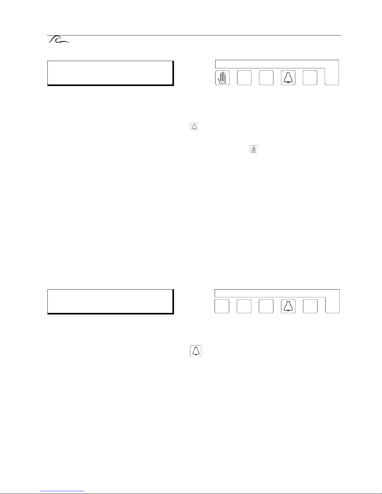
Await regeneration.
This message appears during the regeneration cycle only if there is a "Wait" contact, for example a
water pressure switch intended to prevent regeneration when there is insufficient water pressure,
connected.
Press the "UNLOCK" key indicated by the symbol
, in order to reset the warning or alarm relay. This
will abort any regeneration cycle which is in progress.
Important Note: If the manual regeneration key indicated by the symbol
, is pressed the "Wait" signal
is temporarily neutralised and the regeneration cycle will take place.
The alarm and warning relays and the LCD signals are cleared, as soon as the "wait" signal is removed.
In order to prevent cancellation of the warning before the fault has been cleared it is not possible to
manually reset the message relay.
With duplex installations, operating in standby mode, the stand by unit will be brought on-line if there is a
"wait" signal when a regeneration cycle is initiated.
IMPORTANT If "EURO" is selected at step 12.4 of the programming sequence the outlet (pilot) solenoid
valves will be closed in the service condition.
IMPORTANT Any additional programme (see page 31) will be disabled.
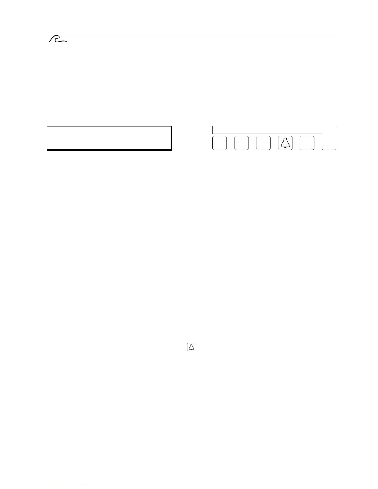
Pre contact (regeneration pre initiation warning).
This message will only be appear, if selected (section 10 of the programming instructions).
Press the "UNLOCK" key indicated by the symbol
, in order to reset the display and the alarm relay,
if programmed. If the warning relay is programmed it cannot be cancelled manually. This is to prevent
premature disconnection of, for example, water analysis equipment.
The display and the relay are automatically cancelled when the regeneration cycle is initiated.
Message
Wait
Message
Pre contact
ES 2050/51 Alarms / warnings 12
Minimum inter regeneration time limit.
This message will only appear if a minimum interval between regeneration’s has been programmed
(section 5 of the programming instructions).
Possible causes when the plant is controlled by a water meter:
Wrongly programmed capacity.
Wrongly programmed incoming water hardness.
The water meter is faulty or of the incorrect type.
Excessive demand for water e.g. a large tank being filled rapidly.
Possible causes when activated by an external water analysis equipment signal:
Poor water quality from a column which has been on standby for some time, due to the contra ion effect.
this can be overcome by fitting a flushing valve or circulation pump in the system or by reducing the
sensitivity of the analytical equipment.
IMPORTANT Regeneration is not initiated. This must be done manually, this prevents repeated
regeneration’s due to a malfunction.
Press the "UNLOCK" key indicated by the symbol
,to restore the display and reset the alarm relay, if
programmed.
Maximum programmed value exceeded.
This indicates that the result of the automatic calculation exchange capacity / hardness lies outside the
permissible range (0.1 - 9999). (Section 9 of the programming instructions)
Message: Maintenance.
This message can only appear when the facility for giving an automatic warning that maintenance is due
has been selected in section 18 of the programming sequence.
Press the "Reset" key with the
symbol in order to reset the alarm relay, if programmed, and call your
maintenance company. The LCD display can only be cleared by trained personnel.
Minimum regene-
ration period
Max display
value exceeded
Maintenance
0031 73 443755
 Loading...