

Page 1
Operating instructions
EN
Control
L1.04 - Expert XQ 2.0
099-00L105-EW501 Observe additional system documents! 07.06.2019
L1.05 - Expert XQ 2.0
Page 2

WARNING
Read the operating instructions!
The operating instructions provide an introduction to the safe use of the products.
• Read and observe the operating instructions for all system components, especially the safety instructions and warning notices!
• Observe the accident prevention regulations and any regional regulations!
• The operating instructions must be kept at the location where the machine is operated.
• Safety and warning labels on the machine indicate any possible risks.
Keep these labels clean and legible at all times.
• The machine has been constructed to state-of-the-art standards in line with any applicable
regulations and industrial standards. Only trained personnel may operate, service and repair the machine.
• Technical changes due to further development in machine technology may lead to a differing welding behaviour.
General instructions
In the event of queries on installation, commissioning, operation or special conditions at the
installation site, or on usage, please contact your sales partner or our customer service
department on +49 2680 181-0.
A list of authorised sales partners can be found at www.ewm-group.com/en/specialist-dealers.
Liability relating to the operation of this equipment is restricted solely to the function of the equipment. No
other form of liability, regardless of type, shall be accepted. This exclusion of liability shall be deemed accepted by the user on commissioning the equipment.
The manufacturer is unable to monitor whether or not these instructions or the conditions and methods
are observed during installation, operation, usage and maintenance of the equipment.
An incorrectly performed installation can result in material damage and injure persons as a result. For this
reason, we do not accept any responsibility or liability for losses, damages or costs arising from incorrect
installation, improper operation or incorrect usage and maintenance or any actions connected to this in
any way.
© EWM AG
Dr. Günter-Henle-Strasse 8
56271 Mündersbach Germany
Tel.: +49 2680 181-0, Fax: -244
Email: [email protected]
www.ewm-group.com
The copyright to this document remains the property of the manufacturer.
Copying, including extracts, only permitted with written approval.
The content of this document has been prepared and reviewed with all reasonable care. The information
provided is subject to change; errors excepted.
Page 3

Contents
Notes on the use of these operating instructions
099-00L105-EW501
07.06.2019
3
1 Contents
1 Contents .................................................................................................................................................. 3
2 For your safety ....................................................................................................................................... 6
2.1 Notes on the use of these operating instructions .......................................................................... 6
2.2 Explanation of icons ....................................................................................................................... 7
2.3 Part of the complete documentation .............................................................................................. 8
3 Intended use ........................................................................................................................................... 9
3.1 Applications .................................................................................................................................... 9
3.2 Use and operation solely with the following machines .................................................................. 9
3.3 Documents which also apply ......................................................................................................... 9
3.4 Software version ............................................................................................................................ 9
4 Quick overview ..................................................................................................................................... 10
4.1 Machine control – Operating elements ........................................................................................ 10
4.2 Screen icons ................................................................................................................................ 12
4.3 Machine display ........................................................................................................................... 13
4.3.1 Actual values, nominal values, hold values .................................................................. 13
4.3.2 Main screen .................................................................................................................. 14
4.3.3 Initial screen ................................................................................................................. 15
5 Operating the machine control ........................................................................................................... 17
5.1 Welding power setting ................................................................................................................. 17
5.2 Direct access keys ....................................................................................................................... 17
5.3 Context-dependent push-buttons ................................................................................................ 17
5.3.1 Changing basic settings (machine configuration menu) .............................................. 17
5.3.2 Lock function ................................................................................................................ 17
5.4 Machine configuration (system) ................................................................................................... 18
5.4.1 Power-saving mode (Standby) ..................................................................................... 18
5.4.2 Access permission (Xbutton) ........................................................................................ 19
5.4.3 Status information ......................................................................................................... 20
5.4.4 System settings ............................................................................................................ 22
5.4.5 Control .......................................................................................................................... 30
5.4.6 Operating panel settings .............................................................................................. 31
5.4.7 Aligning the cable resistance ........................................................................................ 32
5.4.8 Xnet machine ................................................................................................................ 34
5.5 Offline data transfer (USB) .......................................................................................................... 36
5.5.1 Save JOB(s) ................................................................................................................. 36
5.5.2 Load JOB(s) ................................................................................................................. 36
5.5.3 Save configuration ........................................................................................................ 36
4.3.2.1 Main screen variants ..................................................................................... 15
4.3.3.1 Basic settings for operation with two wire feeders (P10) .............................. 16
4.3.3.2 Change system language ............................................................................. 16
5.4.2.1 User information ............................................................................................ 19
5.4.2.2 Activating the Xbutton rights ......................................................................... 19
5.4.3.1 Errors and warnings ...................................................................................... 20
5.4.3.2 Running time ................................................................................................. 21
5.4.3.3 System components ...................................................................................... 21
5.4.3.4 Temperatures ................................................................................................ 21
5.4.3.5 Sensor values ............................................................................................... 21
5.4.4.1 Date ............................................................................................................... 22
5.4.4.2 Time .............................................................................................................. 22
5.4.4.3 Water block ................................................................................................... 22
5.4.4.4 Special parameter ......................................................................................... 23
5.4.8.1 Coupling mobile machines ............................................................................ 34
5.4.8.2 Component identification .............................................................................. 34
5.4.8.3 Component details ........................................................................................ 34
5.4.8.4 Errors and warnings ...................................................................................... 35
5.4.8.5 Status information ......................................................................................... 35
5.4.8.6 Network ......................................................................................................... 35
5.4.8.7 Clear system memory ................................................................................... 35
5.4.8.8 Reset to factory settings ............................................................................... 35
Page 4

Contents
Notes on the use of these operating instructions
4
099-00L105-EW501
07.06.2019
5.5.3.1 System........................................................................................................... 36
5.5.3.2 Xnet machine ................................................................................................ 36
5.5.4 Load configuration ........................................................................................................ 37
5.5.4.1 System........................................................................................................... 37
5.5.4.2 Xnet machine ................................................................................................ 37
5.5.5 Load languages and texts ............................................................................................ 37
5.5.6 Record on USB drive .................................................................................................... 37
5.5.6.1 Register USB drive ........................................................................................ 37
5.5.6.2 Start recording ............................................................................................... 37
5.5.6.3 Stop recording ............................................................................................... 37
5.6 Welding task administration (Menu) ............................................................................................. 38
5.6.1 JOB selection (material/wire/gas) ................................................................................. 38
5.6.2 JOB favourites .............................................................................................................. 39
5.6.2.1 Saving current settings to Favourites ............................................................ 39
5.6.2.2 Loading saved Favourites ............................................................................. 40
5.6.2.3 Deleting saved Favourites ............................................................................. 40
5.6.3 JOB manager ................................................................................................................ 40
5.6.3.1 Copy JOB to number ..................................................................................... 40
5.6.3.2 Reset current JOB ......................................................................................... 40
5.6.3.3 Reset all JOBs ............................................................................................... 40
5.6.4 Program sequence ....................................................................................................... 41
5.6.5 Programs (PA 1-15) ....................................................................................................... 42
5.6.5.1 Overview of the welding parameter switching options .................................. 43
5.6.5.2 MIG/MAG welding ......................................................................................... 45
5.6.5.3 Advanced settings ......................................................................................... 46
5.6.5.4 TIG welding ................................................................................................... 47
5.6.5.5 MMA welding ................................................................................................. 48
5.6.6 Setup mode .................................................................................................................. 49
5.6.7 WPQR welding data assistant ...................................................................................... 50
5.6.8 Welding monitoring ....................................................................................................... 51
5.6.9 JOB display setting ....................................................................................................... 51
5.7 Change welding procedure (Arc) ................................................................................................. 52
5.8 Online data transfer (network) ..................................................................................................... 52
5.8.1 Wired local network (LAN) ............................................................................................ 52
5.8.2 Wireless local network (WiFi) ....................................................................................... 53
6 Welding procedure ............................................................................................................................... 54
6.1 MIG/MAG welding ........................................................................................................................ 54
6.1.1 Welding type ................................................................................................................. 54
6.1.1.1 Welding power (operating point) ................................................................... 54
6.1.1.2 Accessory components for operating point setting ....................................... 54
6.1.1.3 Arc length ...................................................................................................... 54
6.1.1.4 Arc dynamics (choke effect) .......................................................................... 54
6.1.1.5 superPuls ...................................................................................................... 55
6.1.2 Operating modes .......................................................................................................... 55
6.1.2.1 Explanation of signs and functions ................................................................ 55
6.1.2.2 Automatic cut-out .......................................................................................... 67
6.1.3 coldArc XQ / coldArc puls XQ ....................................................................................... 68
6.1.4 forceArc XQ / forceArc puls XQ .................................................................................... 68
6.1.5 rootArc XQ / rootArc pulse XQ ..................................................................................... 69
6.1.6 acArc puls XQ ............................................................................................................... 70
6.1.7 wiredArc ........................................................................................................................ 71
6.1.8 Standard MIG/MAG torch ............................................................................................. 72
6.2 TIG welding .................................................................................................................................. 73
6.2.1 Operating modes (functional sequences) ..................................................................... 73
6.2.1.1 Explanation of signs and functions ................................................................ 73
6.2.1.2 Automatic cut-out .......................................................................................... 73
6.2.2 Arc ignition .................................................................................................................... 77
6.2.2.1 Liftarc ............................................................................................................. 77
6.3 MMA welding ................................................................................................................................ 78
6.3.1 Hotstart ......................................................................................................................... 78
Page 5

Contents
Notes on the use of these operating instructions
099-00L105-EW501
07.06.2019
5
6.3.2 Antistick ........................................................................................................................ 78
6.4 Air arc gouging ............................................................................................................................. 78
7 Rectifying faults ................................................................................................................................... 79
7.1 Display machine control software version ................................................................................... 79
7.2 Warnings ...................................................................................................................................... 80
7.3 Error messages ............................................................................................................................ 81
7.4 Resetting JOBs (welding tasks) to the factory settings ............................................................... 83
8 Appendix ............................................................................................................................................... 84
8.1 Parameter overview – setting ranges .......................................................................................... 84
8.2 JOB-List ....................................................................................................................................... 85
8.3 Searching for a dealer ................................................................................................................. 92
Page 6

For your safety
Notes on the use of these operating instructions
6
099-00L105-EW501
07.06.2019
DANGER
Working or operating procedures which must be closely observed to prevent imminent
serious and even fatal injuries.
• Safety notes include the "DANGER" keyword in the heading with a general warning symbol.
• The hazard is also highlighted using a symbol on the edge of the page.
WARNING
Working or operating procedures which must be closely observed to prevent serious
and even fatal injuries.
• Safety notes include the "WARNING" keyword in the heading with a general warning symbol.
• The hazard is also highlighted using a symbol in the page margin.
CAUTION
Working or operating procedures which must be closely observed to prevent possible
minor personal injury.
• The safety information includes the "CAUTION" keyword in its heading with a general warning symbol.
• The risk is explained using a symbol on the edge of the page.
Technical aspects which the user must observe to avoid material or equipment damage.
2 For your safety
2.1 Notes on the use of these operating instructions
Instructions and lists detailing step-by-step actions for given situations can be recognised via bullet
points, e.g.:
• Insert the welding current lead socket into the relevant socket and lock.
Page 7
For your safety
Explanation of icons
099-00L105-EW501
07.06.2019
7
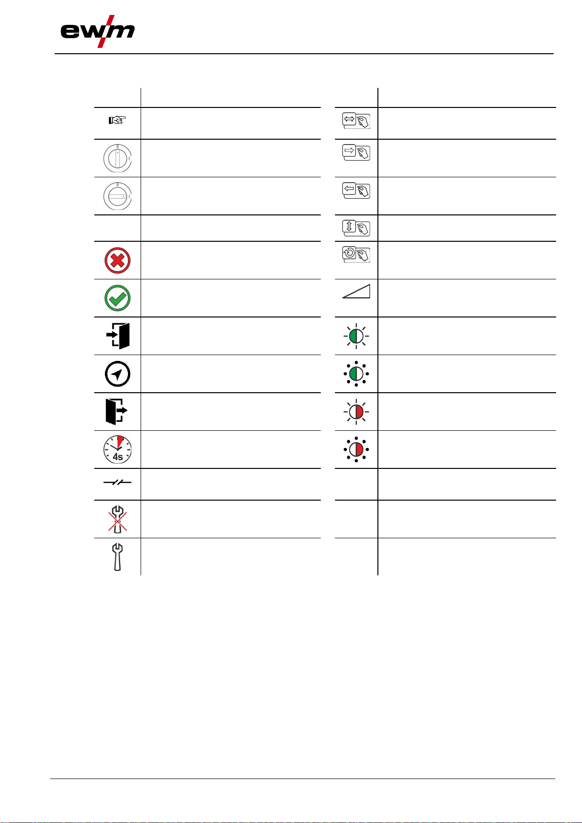
Symbol
Description
Symbol
Description
Indicates technical aspects which the
user must observe.
Activate and release / Tap / Tip
Switch off machine
Release
Switch on machine
Press and hold
Switch
Incorrect / Invalid
Turn
Correct / Valid
Numerical value – adjustable
Input
Signal light lights up in green
Navigation
Signal light flashes green
Output
Signal light lights up in red
Time representation (e.g.: wait 4 s /
actuate)
Signal light flashes red
Interruption in the menu display (other
setting options possible)
Tool not required/do not use
Tool required/use
2.2 Explanation of icons
Page 8
For your safety
Part of the complete documentation
8
099-00L105-EW501
07.06.2019
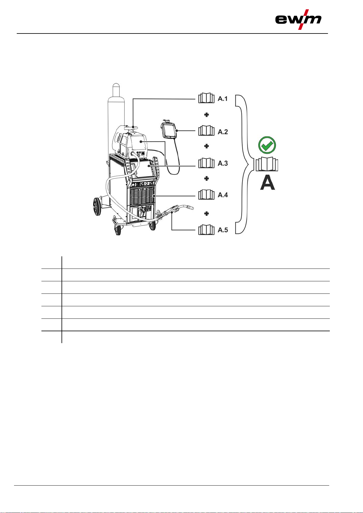
Item
Documentation
A.1
Wire feeder
A.2
Remote adjuster
A.3
Controller
A.4
Power source
A.5
Welding torch
A
Complete documentation
2.3 Part of the complete documentation
These operating instructions are part of the complete documentation and valid only in
combination with all other parts of these instructions! Read and observe the operating
instructions for all system components, especially the safety instructions!
The illustration shows a general example of a welding system.
Figure 2-1
The illustration shows a general example of a welding system.
Page 9
Intended use
Applications
099-00L105-EW501
07.06.2019
9
WARNING
Hazards due to improper usage!
The machine has been constructed to the state of the art and any regulations and
standards applicable for use in industry and trade. It may only be used for the welding
procedures indicated at the rating plate. Hazards may arise for persons, animals and
material objects if the equipment is not used correctly. No liability is accepted for any
damages arising from improper usage!
• The equipment must only be used in line with its designated purpose and by trained or
expert personnel!
• Do not improperly modify or convert the equipment!
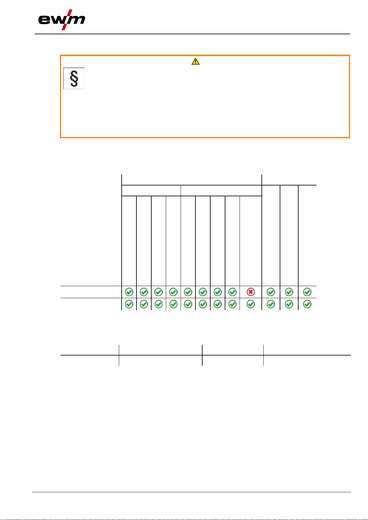
Machine series
Main procedure for MIG/MAG welding
Secondary process
Standard arc
Pulsed arc
TIG welding (lift arc)
MMA welding
Gouging
MIG/MAG XQ
forceArc XQ
rootArc XQ
coldArc XQ
MIG/MAG pulse XQ
forceArc puls XQ
rootArc puls XQ
coldArc puls XQ
acArc puls XQ
Titan XQ / XQ C
Titan XQ AC
Machine control
Expert XQ 2.0
Expert XQ 2.0 LG
Expert XQ 2.0 WLG
Description
No network connection
Version with LAN
Version with Wi-Fi and LAN
3 Intended use
3.1 Applications
Device control of multi-process welding machines for arc welding covering the following welding procedures:
3.2 Use and operation solely with the following machines
The following system components can be combined:
This description may be applied only to machines with the Expert XQ 2.0 machine control.
3.3 Documents which also apply
• Operating instructions for the connected welding machines
3.4 Software version
• Documents of the optional expansions
These instructions apply to the following software version:
2.0.D.0
The machine control software version is shown on the screen during the start
process > see 4.3.3 chapter.
Page 10
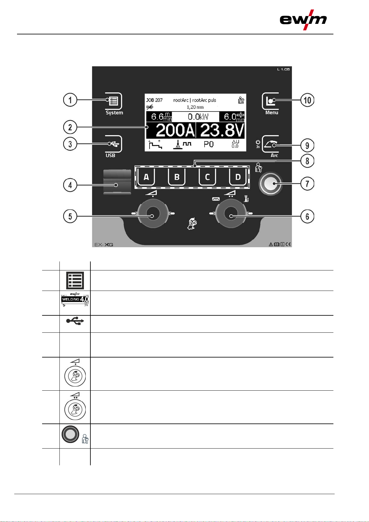
Quick overview
Machine control – Operating elements
10
099-00L105-EW501
07.06.2019
Item
Symbol
Description 0
1
System push-button
To display and configure the system settings > see 5.4.4 chapter.
2
Machine display
Graphical machine display showing all machine functions, menus and parameters with
their values > see 4.3 chapter.
3
USB push-button
To use and configure the USB interface > see 5.5 chapter.
4
USB interface for offline data transfer
Connection capability for a USB flash memory (industrial USB flash memory recommended).
5
Click wheel welding power
• ---------- Setting the welding power > see 5.1 chapter
• ---------- Setting various parameters values depending on the preselection.
It is possible to adjust settings when the backlight is activated.
6
Click wheel correction of arc
• ---------- Setting the correction of arc length > see 6.1.1.3 chapter
• ---------- Setting the arc dynamics > see 6.1.1.4 chapter
It is possible to adjust settings when the backlight is activated.
7
Interface (Xbutton)
Welding access based on user-defined rights to protect against unauthorised
use > see 5.4.2 chapter.
8
A B C D
Context-dependent push-button
> see 5.3 chapter
4 Quick overview
4.1 Machine control – Operating elements
Figure 4-1
Page 11
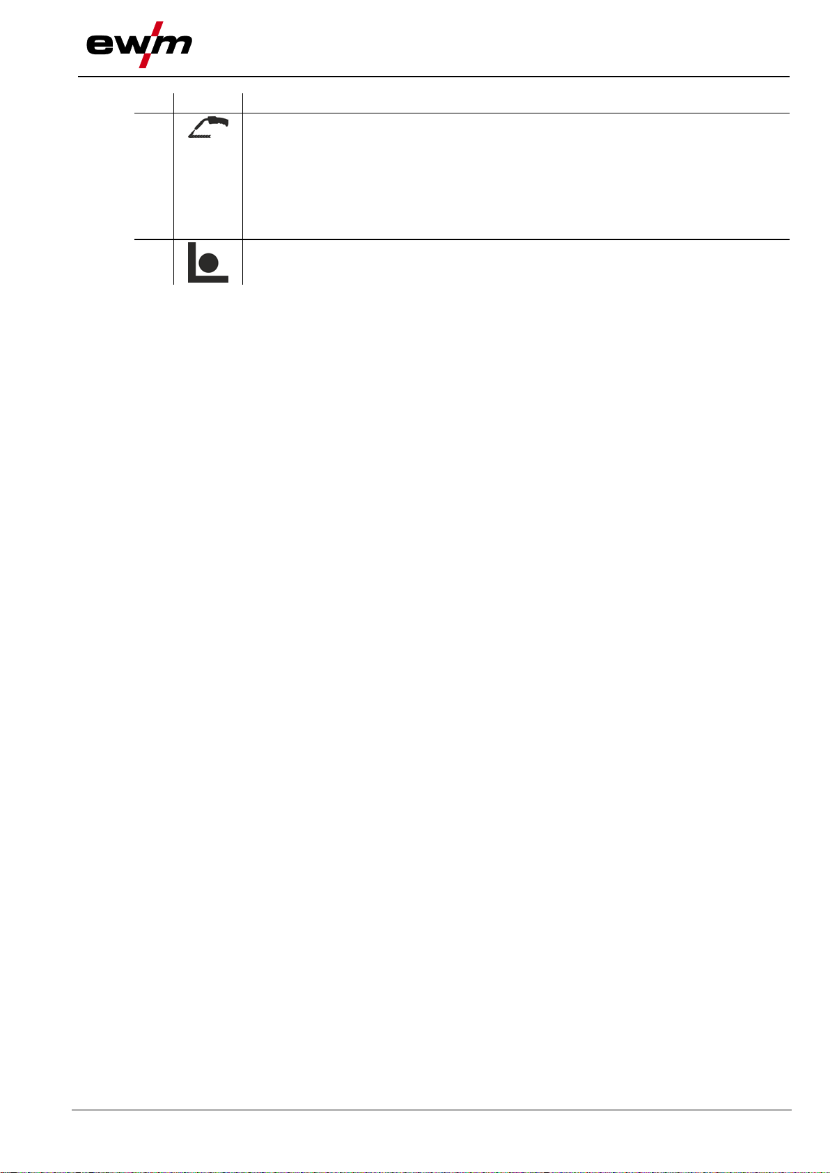
Quick overview
Machine control – Operating elements
099-00L105-EW501
07.06.2019
11
Item
Symbol
Description 0
9
Arc push-button
• Initial state of main screen: Switching of the welding procedure based on the selected material, gas and welding consumable.
• Initial state of any sub-menu: Display switches back to the main screen.
• Press and hold: After 3 s, the machine switches into locked mo-
de > see 5.3.2 chapter.
To unlock, press and hold again for 3 s > see 5.3.2 chapter.
10
Menu push-button
To organise welding tasks and configure process parameters.
Page 12
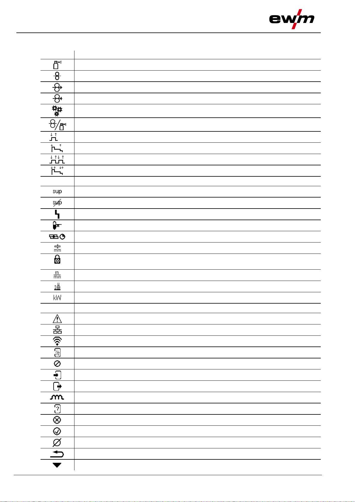
Quick overview
Screen icons
12
099-00L105-EW501
07.06.2019
Symbol
Description
Shielding gas
Material type
Wire inching
Wire return
Advanced settings
Set-up mode
Non-latched operating mode
Special non-latched operating mode
Latched operating mode
Special latched operating mode
JOB
Welding task
superPuls
superPuls switched off
Interference
Temperature error
Spot welding operating mode
Material thickness
Disabled; selected function is not available with the current access rights - check access
rights.
Wire feed speed
Arc length correction
Welding power
P
Programs (P0 - P15) > see 5.6.5 chapter
Warning; could be an imminent interference
Wired local network (LAN)
Wireless local network (WiFi)
User logged in
Not possible, check priorities
Xbutton login
Xbutton logout
Arc dynamics
Xbutton version number not recognised
Cancel operation
Confirm operation
Wire diameter (welding consumable)
Menu navigation; one menu back
Menu navigation; expanding the content of the display
4.2 Screen icons
Page 13
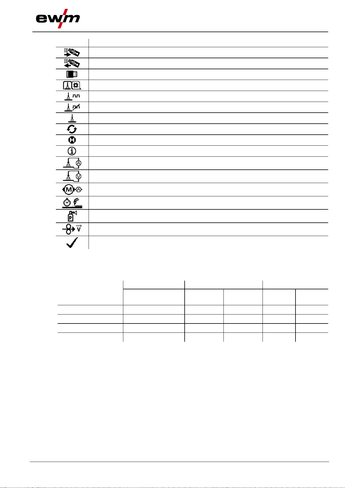
Quick overview
Machine display
099-00L105-EW501
07.06.2019
13
Symbol
Description
Save data to USB medium
Load data from USB medium
USB data recording
Screen type 3/4, switching buttons
Pulse arc welding
Standard arc welding
Welding procedure
Refresh
After welding, the last weld values (hold values) from the main program are displayed
Information
Welding current
Welding voltage
Motor current, wire feed motor
Welding duration
Plasma gas
Wire feed speed
Value correct or applicable
Parameter
Before welding
During welding
After welding
Nominal value
Actual value
Nominal
value
Hold
value
Nominal
value
Welding current
Material thickness
Wire feed speed
Welding voltage
4.3 Machine display
The machine display shows all the information relevant to the user as text and/or graphics.
4.3.1 Actual values, nominal values, hold values
Page 14
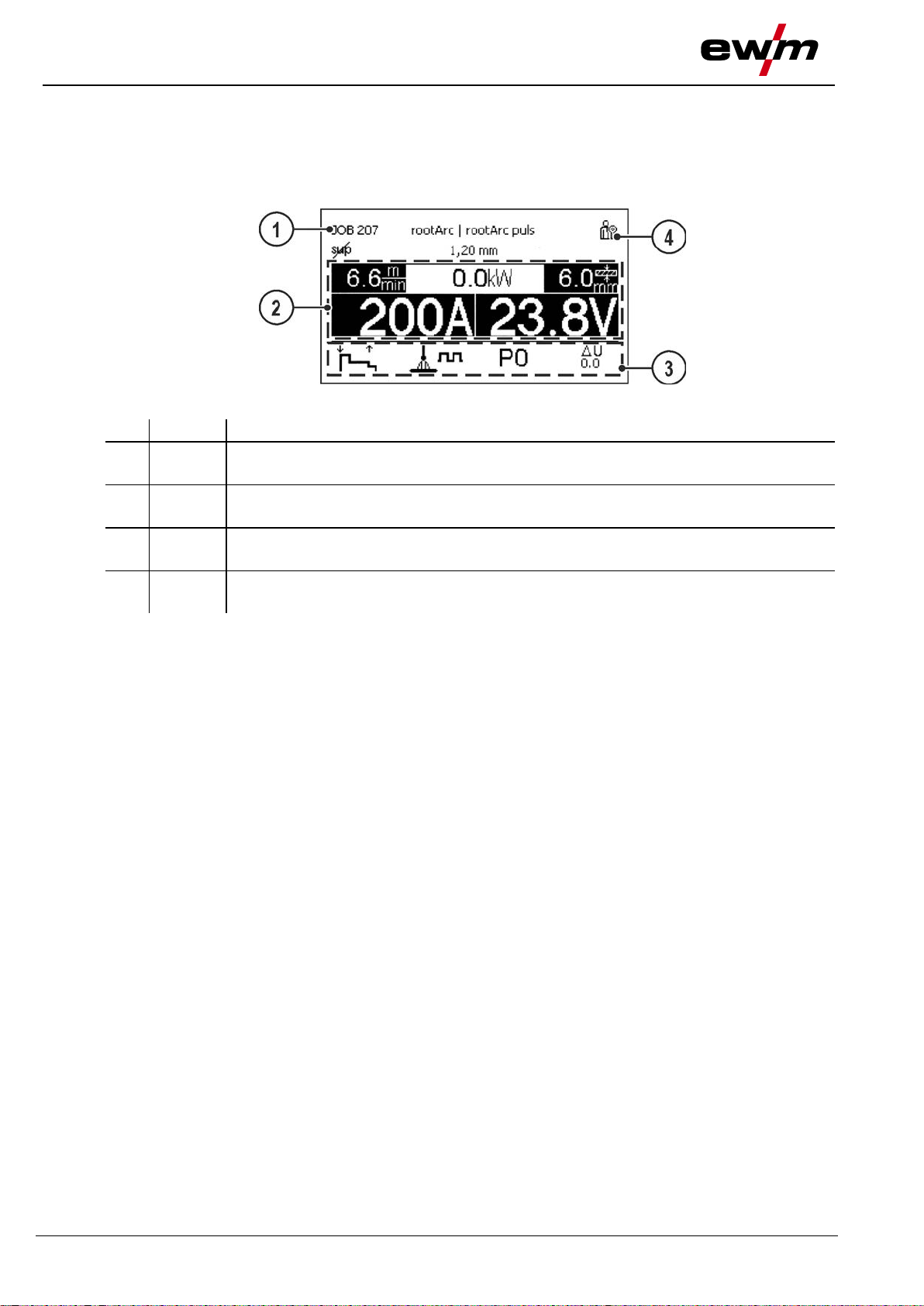
Quick overview
Machine display
14
099-00L105-EW501
07.06.2019
Item
Symbol
Description 0
1
Information on the welding task selected
JOB number, process etc.
2
Display area for welding data
Welding current, welding voltage, wire feed speed, material thickness etc.
3
Display area for process parameters
Operating mode, voltage correction, program, welding method etc.
4
Display area for system status
Network status, error status etc. > see 4.2 chapter
4.3.2 Main screen
The main screen shows all the information relevant for the welding process before, while and after it is
carried out. In addition, it shows status information on the machine state. The assignment of the contextdependent push-buttons is also shown on the main screen.
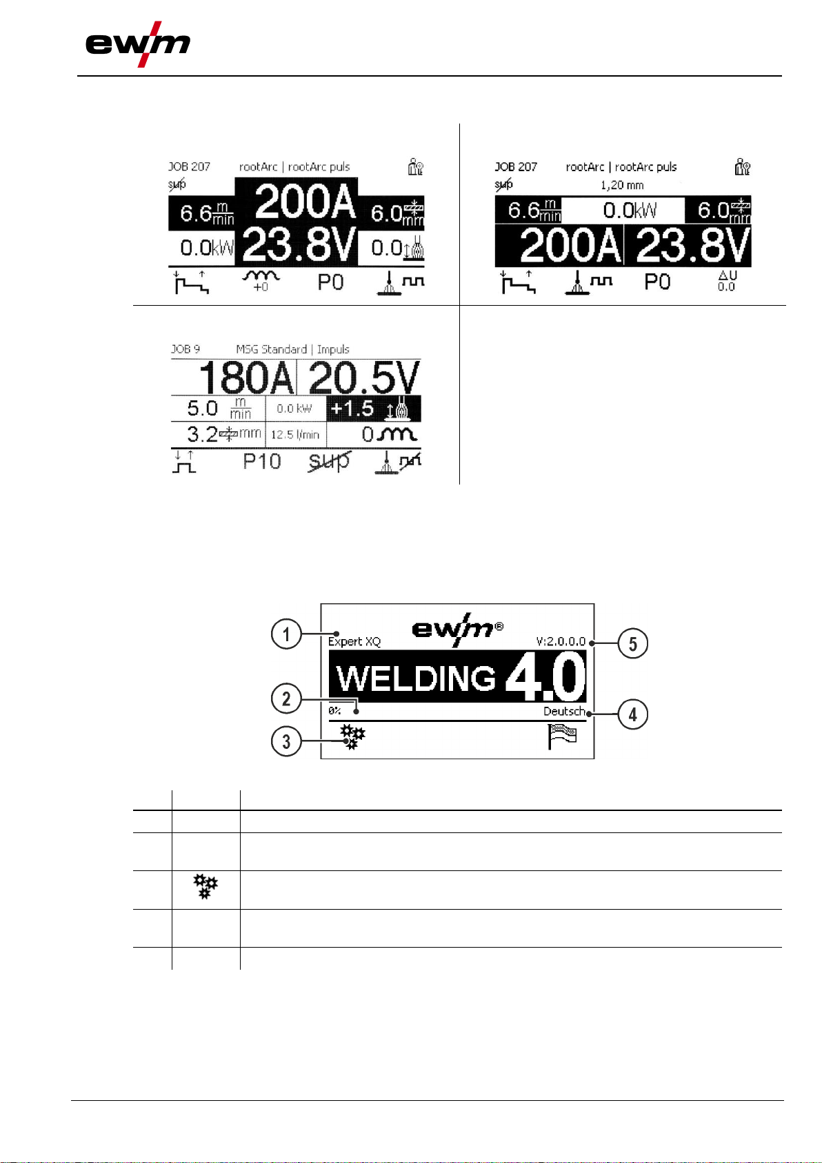
The user can choose between different main screens > see 4.3.2.1 chapter.
Figure 4-2
By pressing push-button A for a prolonged time (on the operating mode main screen) it is possible to directly switch to the program sequence.
Page 15
Quick overview
Machine display
099-00L105-EW501
07.06.2019
15
Main screen type 1
Main screen type 2 (ex works)
Main screen type 3
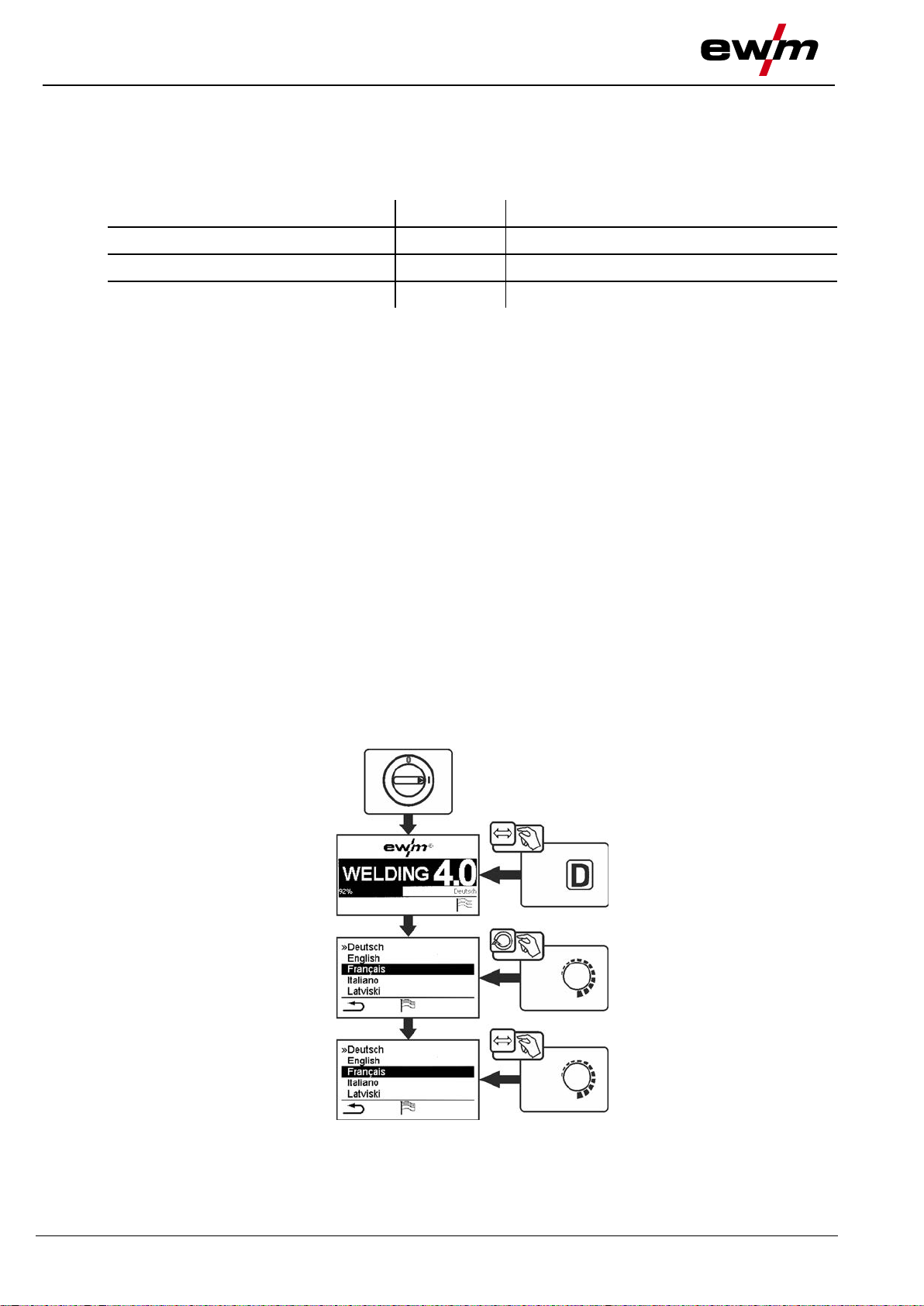
Item
Symbol
Description 0
1
Machine control name
2
Progress bar
Shows the load progress during the start process.
3
Advanced settings
Display and setting of advanced system parameters > see 4.3.3.1 chapter
4
Indication of the system language selected
The system language can be changed during the start process > see 4.3.3.2 chapter.
5
Control software version
4.3.2.1 Main screen variants
You can select the required variant (type of main screen) in the Machine configuration (system)
menu > see 5.4.6 chapter.
4.3.3 Initial screen
During the start process the control name, machine software version and selected language are shown
on the screen.
Figure 4-3
Figure 4-4
Page 16
Quick overview
Machine display
16
099-00L105-EW501
07.06.2019
Menu item/parameter
Value
Comment
DVX (single)
0
DVX-Unit 1 (master)
1
DVX-Unit 2 (slave)
2
4.3.3.1 Basic settings for operation with two wire feeders (P10)
The setting is available/required in the following cases only:
• the control is integrated in the wire feeder
• the control is integrated in the power source (compact design)
With single unit operation (P10 = 0) a second wire feeder may not be connected!
• Remove any connections to the second wire feeder
With double unit operation (P10 = 1 or 2) both wire feeders have to be connected and be set up for
this operation at the control with different configurations.
• Configure one wire feeder as master (P10 = 1)
• Configure the other wire feeder as slave (P10 = 2)
Access control
If one of the wire feeders in the welding system is equipped with an access control key switch, it has to be
configured as master (P10 = 1). With double unit operation, if more than one wire feeder is equipped with
an access control key switch, either one can be configured as master. The wire feeder configured as
master is active as soon as the welding machine has been switching on. There are no other functional differences between the wire feeders.
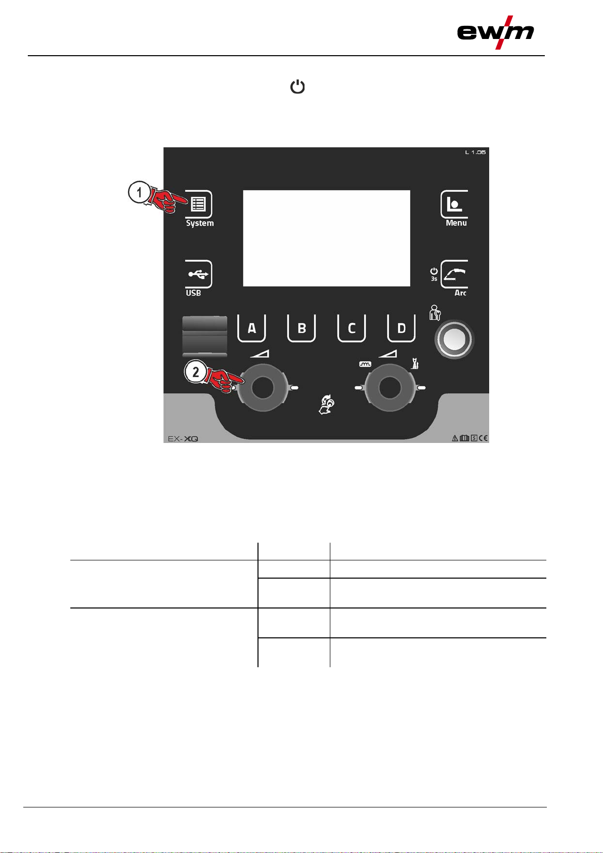
4.3.3.2 Change system language
During the start process the user can select or change the system language at the machine control.
• Switch the machine off and on again.
• Press the context-dependent push-button [D] during the start phase (the word WELDING 4.0 is displayed).
• Select the required language by turning the control button.
• Confirm the selected language by pressing the control button (the user can exit the menu by pressing
the context-dependent push-button [A] without making any changes).
Figure 4-5
Page 17

Operating the machine control
Welding power setting
099-00L105-EW501
07.06.2019
17
5 Operating the machine control
In general the control is operated with the central control button below the machine display.
Select the required menu item by turning (navigate) and pressing (confirm) the central control button. In
addition, the context-dependent push-buttons below the machine display can be used for confirmation.
5.1 Welding power setting
The welding power is adjusted with the rotary knob (click wheel) for welding power. You can also adjust
the parameters in the operation sequence or settings in the various machine menus.
MIG/MAG settings
The welding power (heat input into the material) can be changed by setting the following three parameters:
• wire feed speed
• material thickness
• welding current A
These three parameters are interdependent and always change together. The significant parameter is the
wire feed speed in m/min. The wire feed speed can be adjusted in increments of 0.1 m/min (4.0 ipm). The
associated welding current and material thickness are determined from the wire feed speed.
The welding current displayed and material thickness are to be understood as guide values for the user
and rounded to full amperage and 0.1 mm material thickness.
A change in the wire feed speed, for example by 0.1 m/min, leads to a more or less large change in the
welding current displayed or in the material thickness displayed depending on the selected welding wire
diameter. The display of the welding current and the material thickness are also dependent on the selected wire diameter.
For example, a change in wire feed speed of 0.1 m/min and a selected wire diameter of 0.8 mm results in
a smaller change in the current or thickness of material than a change in wire feed speed of 0.1 m/min
and a selected wire diameter of 1.6 mm.
Depending on the diameter of the wire to be welded, it is possible that smaller or larger jumps in the display of material thickness or welding current take place or changes of these values become visible only
after several “clicks” on the rotary transducer. As described above, the reason for this is the change in the
wire feed speed by 0.1 m/min per click and the resulting change in the current or material thickness as a
function of the preselected welding wire diameter.
Please note also that the guide value of the welding current displayed before welding may deviate from
the guide value during welding depending on the actual stick-out (free wire end used for welding).
The reason lies in the preheating of the free wire end by the welding current. For example, the preheating
in the welding wire increases with the length of the stick-out. This means if the stick-out (free wire end) increases, the actual welding current decreases due to larger preheating in the wire. If the free wire end
decreases, the actual welding current increases. This enables the welder to influence the heat input in the
component within limits by changing the distance of the welding torch.
Setting of TIG/MMA:
The welding power is set with the parameter “welding current” that can be adjusted in increments of 1
ampere.
5.2 Direct access keys
5.3 Context-dependent push-buttons
5.3.1 Changing basic settings (machine configuration menu)
5.3.2 Lock function
Several push-buttons on the right and left of the display can be used to directly access the most important
menus.
The bottom push-buttons are so-called context-dependent operating elements. The selection options of
these buttons depend on each screen content.
If the icon is shown on the display the user can skip back to the previous menu item (often assigned
to the [A] push-button).
The basic welding system functions can be adjusted in the machine configuration menu. Only experi-
enced users should change the settings > see 5.4 chapter.
The lock function protects against accidental adjustment of the device settings.
Page 18
Operating the machine control
Machine configuration (system)
18
099-00L105-EW501
07.06.2019
Menu item/parameter
Value
Comment
Time automatic [min.]
Off
Function switched off
5-60
Time to activation of the power-saving mode in
case of inactivity.
Log off user in standby mode
Yes
The user will be logged off when the powersaving mode is active.
No
The user will not be logged off when the powersaving mode is active.
The user can switch the lock function on or off by pressing the button for a long time from each machine
control or accessory component with the symbol .
5.4 Machine configuration (system)
In the System menu the user can set the basic machine configuration.
Enter the menu:
5.4.1 Power-saving mode (Standby)
You can activate the power-saving mode by setting a parameter in the configuration menu (timecontrolled power-saving mode). When power-saving mode is active, the Expert XQ 2.0 machine controller
display is dimmed and only the middle digit of the display is shown in the wire feed unit. Pressing any
operating element (e.g. tapping the torch trigger) deactivates power-saving mode and the machine is
ready for welding again.
Figure 5-1
Page 19

Operating the machine control
Machine configuration (system)
099-00L105-EW501
07.06.2019
19
Menu item/parameter
Value
Comment
Xbutton rights active:
Yes
Access rights active
No
Key switch active
Reset Xbutton configuration:
Yes
Company ID, group and access rights when
logged off will be reset to the factory settings.
Xbutton rights will be deactivated.
No
5.4.2 Access permission (Xbutton)
The welding system offers two options to prevent unauthorised access to welding parameters or unintentional reconfiguration.
1 Key switch (available depending on machine version). With the key switch in position 1 all functions
and parameters can be configured without any restriction. In position 0 certain predefined
welding parameters or functions cannot be modified (see relevant documentation).
2 Xbutton. With this function, permissions can be assigned to users to access those areas of the machi-
ne control defined for them. To do so, the user needs a digital key (Xbutton) to log on to the machine
via the Xbutton interface. The key itself is configured by the system user (welding supervisor).
If the Xbutton function is activated, the key switch/key switch function is deactivated.
To activate Xbutton rights follow these instructions:
1. Set key switch to position "1".
2. Log on with a Xbutton and administrator rights.
3. Set menu option "Xbutton rights active" to "yes".
By following these instructions you make sure not to inadvertently block your access while not owning an
Xbutton with administrator rights.
5.4.2.1 User information
User information such as company ID, user name, group etc. are shown.
5.4.2.2 Activating the Xbutton rights Menu navigation:
Figure 5-2
Page 20
Operating the machine control
Machine configuration (system)
20
099-00L105-EW501
07.06.2019
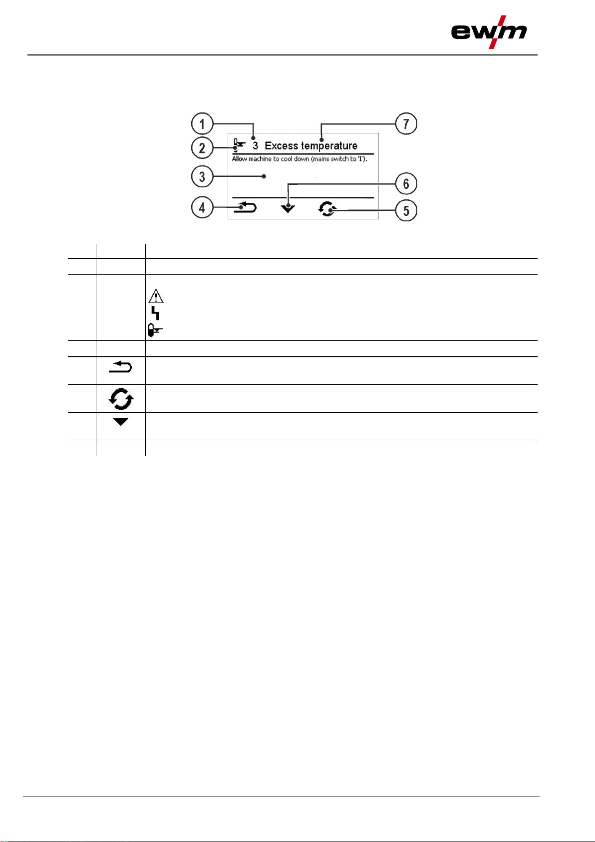
Item
Symbol
Description 0
1
Error number > see 7.3 chapter
2
Error icons
------- Warning (prior to interference)
------- Interference (welding process will be stopped)
------- Specific (e.g. temperature error)
3
Long error description
4
Menu navigation
Skip back to previous menu
5
Reset message
The message can be reset
6
Menu navigation (if available)
Scroll to next page or message
7
Error name
5.4.3 Status information
This menu provides the user with information on current system interferences and warnings..
5.4.3.1 Errors and warnings
Figure 5-3
Page 21
Operating the machine control
Machine configuration (system)
099-00L105-EW501
07.06.2019
21
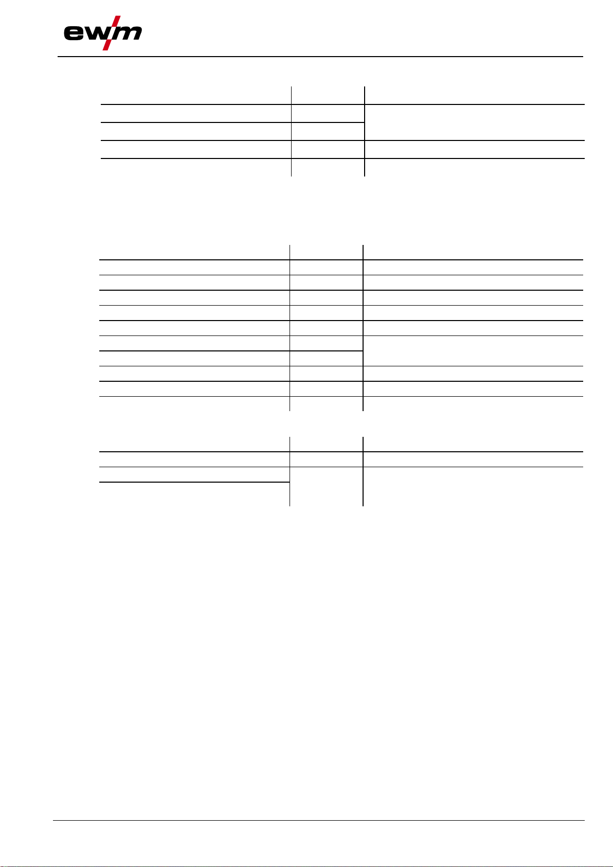
Menu item/parameter
Value
Comment
Duty cycle can be reset:
0:00 h
Values can be reset by pressing or turning the
main control button
Arc time can be reset:
0:00 h
Overall duty cycle:
0:00 h
Overall arc time:
0:00 h
Menu item / parameter
Value
Comment
Housing inside
- - Transformer secondary
- - RCC heatsink
-
-
Coolant return
- - Primary heatsink
-
-
Wire heater, unit 1
-
Display of “---” if no wire heater is installed
Wire heater, unit 2
-
Temperature 8
-
free
Temperature 9
-
free
Temperature 10
-
free
Menu item / parameter
Value
Comment
Coolant flow
-
-
Wire reserve, unit 1
0-100%
Display of “---” if no wire sensor is installed or
value could not yet be determined (at least one
reel revolution required).
Wire reserve, unit 2
5.4.3.2 Running time
5.4.3.3 System components
A list of all components available in the system is displayed, along with ID number, software version and
name.
5.4.3.4 Temperatures
5.4.3.5 Sensor values
Page 22
Operating the machine control
Machine configuration (system)
22
099-00L105-EW501
07.06.2019
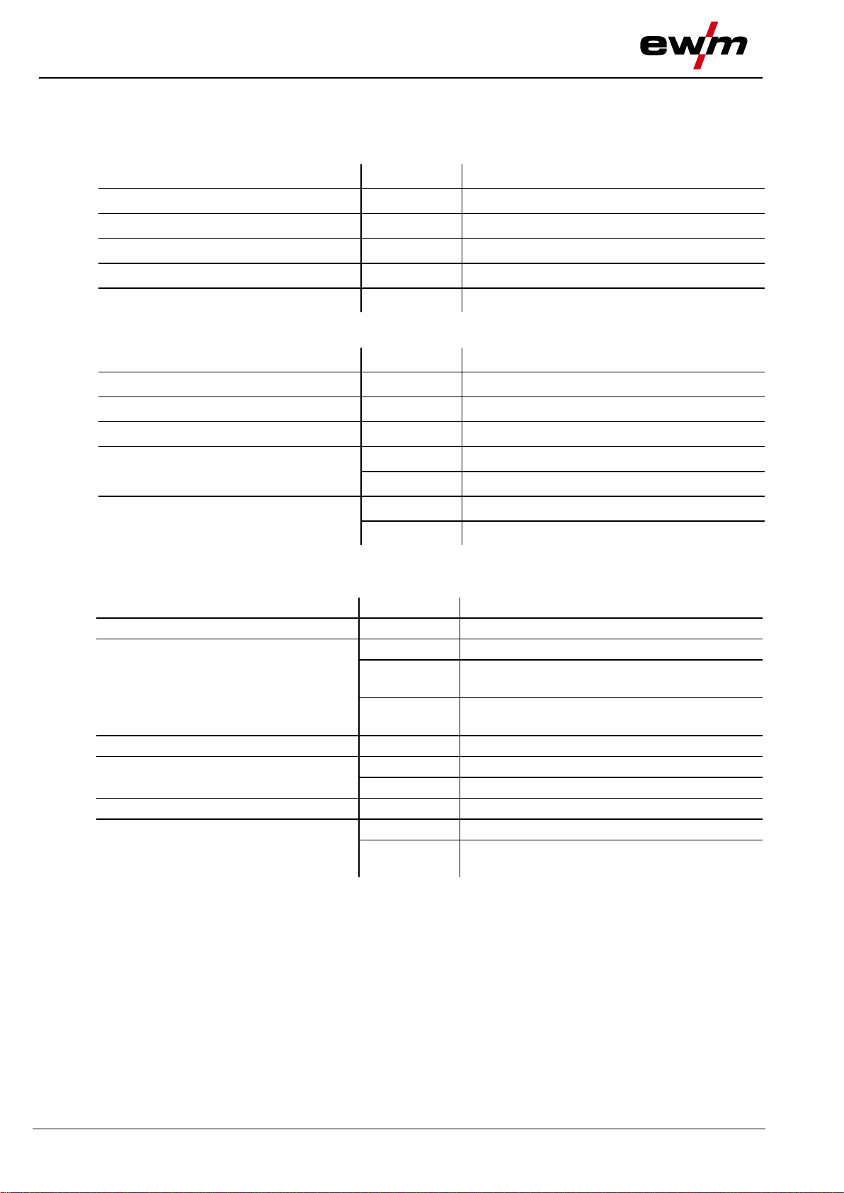
Menu item/parameter
Value
Comment
Year:
2014
Month:
10
Day:
28
Date format:
DD.MM.YYYY
YYYY.MM.DD
Menu item/parameter
Value
Comment
Hour:
0–24
Minute:
0–59
Time zone (UTC +/-):
-12h to +14h
Summer time:
Yes
No
Time format:
24 h
12 h AM/PM
Menu item / parameter
Value
Comment
Cooling unit postflow time [min.]:
1-60 min
Cooling unit control:
Automatic
Permanently
ON
Permanently
OFF
Temperature error limit
50-80 °C
Flow monitoring
On
Off Flow error limit
0.5-2.0 l/min
Reset to factory setting
No
Yes
Resets the water block parameters to factory
settings.
5.4.4 System settings
In this area the user can configure advanced system settings.
5.4.4.1 Date
5.4.4.2 Time
5.4.4.3 Water block
Permanently switching off the water block may damage the welding torch.
Page 23
Operating the machine control
Machine configuration (system)
099-00L105-EW501
07.06.2019
23
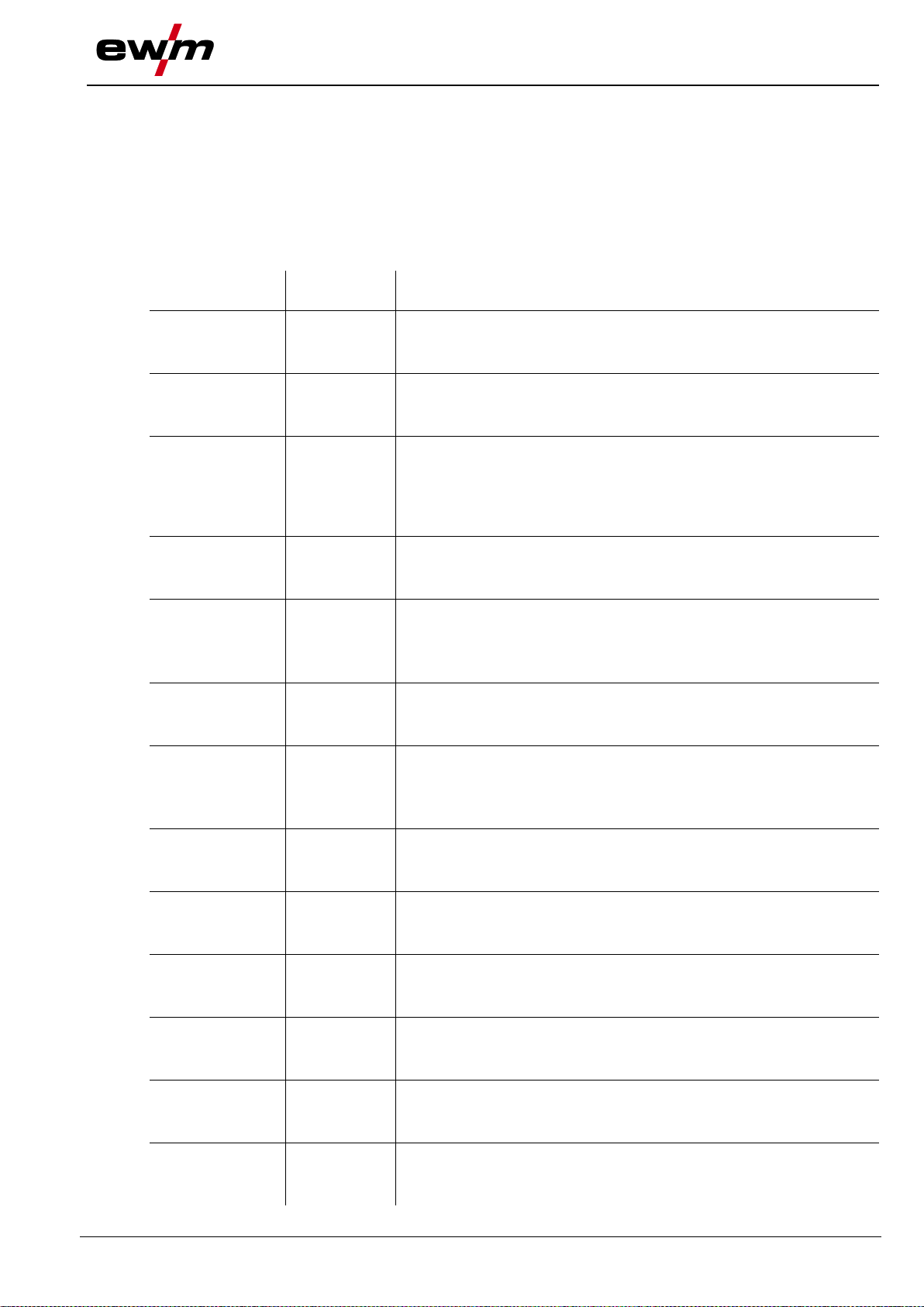
Menu item/parameter
Value
Comment
P1
1-0
Wire inching / wire return ramp time
0 =-------- normal inching (10 s ramp time)
1 =-------- fast inching (3 s ramp time) (ex works)
P2
0-1
Block program "0"
0 =-------- Enabled (ex works)
1 =-------- P0 blocked
P3
0-1
Display mode for Up/Down welding torch with one-digit 7-segment
display (two keys)
0 =-------- Normal display (ex works) program number/welding power
(0–9)
1 =-------- Display toggles between program number/welding type
P7
0-1
Correction operation, limit value setting
0 =-------- Correction operation switched off (ex works)
1 =-------- Correction operation switched on
P8
0-1
Program switching with standard welding torch
0 =-------- No program switching (ex works)
1 =-------- Special latched
2 =-------- Special latched (n-cycle active)
P9
0-1
Tapping start for latched and special latched operation
0 =-------- no 4-cycle inching start
1 =-------- 4-cycle inching start possible (ex works)
P11
0-1
Special latched tapping time
0 =-------- Tapping function switched off.
1 =-------- 300 ms (ex works)
2 =-------- 600 ms
P12
1-2
JOB list switching
1 =-------- Real JOB list (ex works)
2 =-------- Real JOB list and JOB switching activated via accessories
P13
129
Lower limit remote JOB switching
JOB range of the function torches (MT PC2, PM 2U/D, PM RD2)
Lower limit: 129 (ex works)
P14
169
Upper limit remote JOB switching
JOB range of the function torches (MT PC2, PM 2U/D, PM RD2)
Upper limit: 169 (ex works)
P16
0-1
JOB batch mode
0 =-------- Block JOB mode not enabled (ex works)
1 =-------- Block JOB mode enabled
P17
0-1
Program selection with standard torch trigger
0 =-------- No program selection (ex works)
1 =-------- Program selection possible
P23
0-1
Program settings for relative programs
0 =-------- Combined setting of relative programs possible (ex works).
1 =-------- Individual setting of relative programs possible.
5.4.4.4 Special parameter
The special parameters of the wire feeder control are used to customize the machine function configuration.
The number of selectable special parameters can deviate between the machine controls used in the
welding system.
It may be required to restart the machine in order to apply a parameter change.
Systems with two wire feeder controls show the parameters of the active wire feeder only (special para-
meter U1 or special parameter U2).
Page 24

Operating the machine control
Machine configuration (system)
24
099-00L105-EW501
07.06.2019
Menu item/parameter
Value
Comment
P26
45 °C
Nominal value of wire spool heater (OW WHS)
0 = -------- off = switched off
1 = -------- setting range temperature: 25°C - 50°C (45°C ex works)
P27
0-1
Operating mode switching at welding start
0 = -------- Not enabled (factory setting)
1 = -------- Enabled
P28
30 %
Error threshold of electronic gas flow control
Error output in case of gas nominal value deviation
Reset to factory
setting:
No
Yes
All special parameters are reset to the corresponding factory setting.
Wire inching ramp time (P1)
The wire inching starts with a speed 1.0 m/min for 2 secs. It is subsequently increased to a ramp function
to 6.0 m/min. The ramp time can be set between two ranges.
During wire inching, the speed can be changed by means of the welding power rotary knob. Changing the
speed has no effect on the ramp time.
Program “0”, release of program block (P2)
The program P0 (manual setting) is blocked. Only operation with P1-P15 is possible, irrespective of the
key switch position.
Display mode for Up/Down welding torch with one-digit 7-segment display (P3)
Normal display:
• Program mode: Program number
• Up/down operation: Welding power (0=minimum current/9=maximum current)
Toggling display:
• Program mode: Program number and welding procedure (P=pulse/n=not pulse) are toggled
• Up/down operation: Welding power (0=minimum current/9=maximum current) and symbol for up/down
operation are toggled
Page 25
Operating the machine control
Machine configuration (system)
099-00L105-EW501
07.06.2019
25
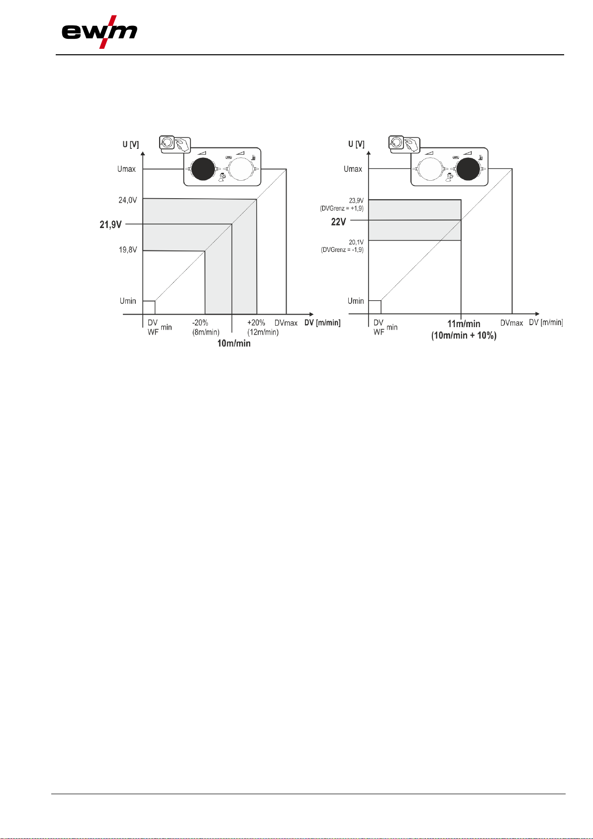
Switching on/off correction operation (P7)
The correction operation is switched on and off for all JOBs and their programs at the same time. A correction operation is specified for wire speed (DV) and welding voltage correction (Ukorr) for each JOB.
The correction value is saved separately for each program. The correction range can be maximum 30%
of the wire speed and +/-9.9 V welding voltage.
Figure 5-4
Example for the operating point in correction mode:
The wire speed in one program (1 to 15) is set on 10.0 m/min.
This corresponds to a welding voltage (U) of 21,9 V. When the key switch is set to "0" position, welding in
this program can only be carried out with these values.
To allow the welder also to perform wire and voltage correction in program mode, the correction mode
must be switched on and limit values for wire and voltage must be specified.
Setting of the correction limit value = WFlimit = 20% / Ulimit = 1.9 V
Now the wire speed can be corrected by 20% (8.0 up to 12.0 m/min) and the welding voltage by +/-1.9 V
(3.8 V).
In the example the wire speed is set on 11.0 m/min. This corresponds to a welding voltage of 22 V
Now the welding voltage can be corrected by further 1.9 V (20.1 V and 23.9 V).
The values for voltage and wire-speed correction will be reset if the key switch is moved to the "1"
setting.
Page 26
Operating the machine control
Machine configuration (system)
26
099-00L105-EW501
07.06.2019
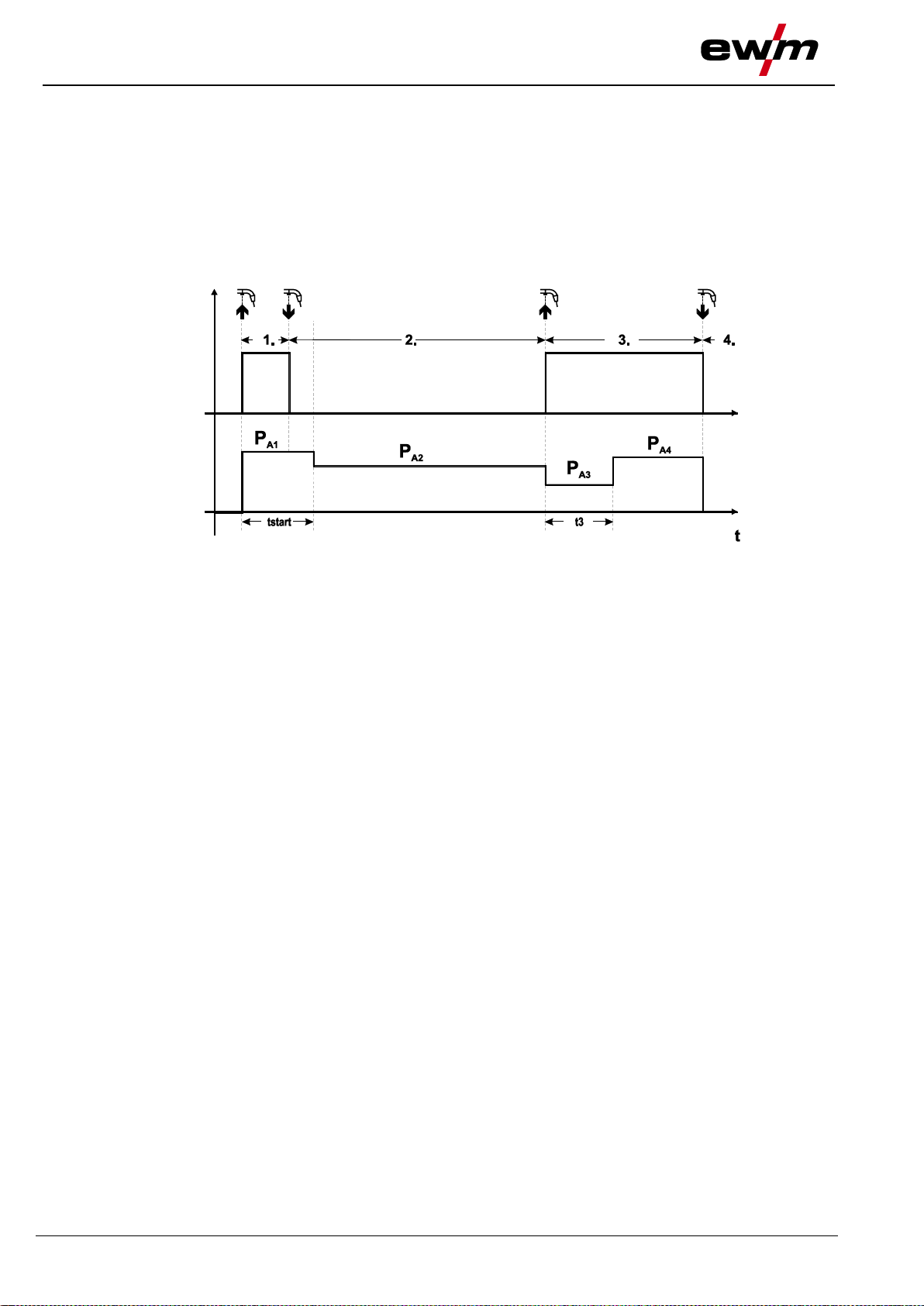
Program switching with standard welding torch (P8)
Special latched (latched absolute program sequence)
• Cycle 1: absolute program 1 is run
• Cycle 2: absolute program 2 is run after completion of "tstart".
• Cycle 3: absolute program 3 is run until the "t3" time has elapsed. The program then switches automatically to absolute program 4.
Accessory components such as remote controls or special torches may not be connected!
Program switching at the wire feed unit control is disabled.
Figure 5-5
Page 27
Operating the machine control
Machine configuration (system)
099-00L105-EW501
07.06.2019
27
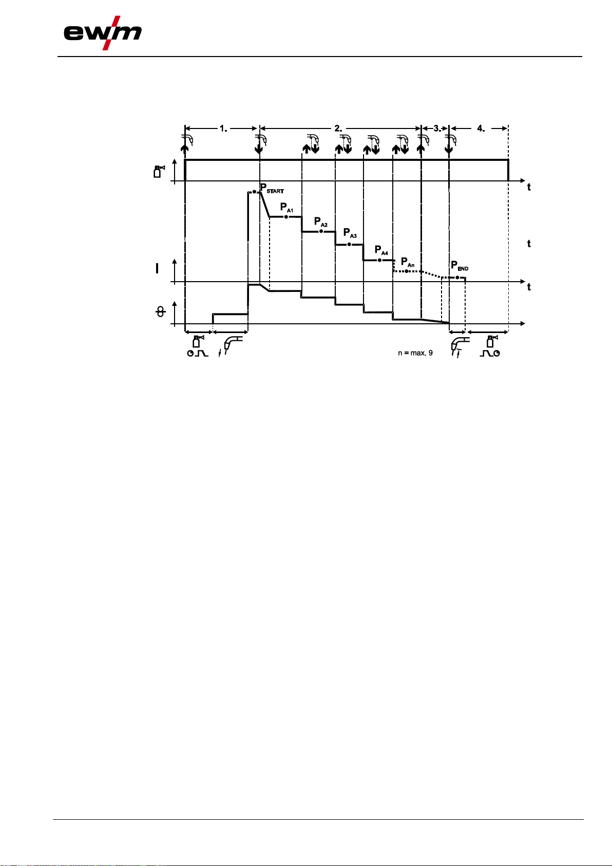
Specific latched special (n cycle)
In the n cycle program sequence, the unit starts in the 1st cycle with start program P
start
from P
1
In the second cycle, the machine switches to absolute program 2, once the start time "tstart" has elapsed.
Tapping switches to other programs (PA1 to max. PA9).
Figure 5-6
The number of programs (PAn) corresponds to the cycle number specified under N cycle.
1st cycle
• Press and hold torch trigger.
• Shielding gas is expelled (gas pre-flows).
• Wire feed motor runs at "creep speed".
• Arc ignites after the wire electrode makes contact with the workpiece, welding current is flowing (start
program P
START
from PA1)
2nd cycle
• Release torch trigger.
• Slope to main program PA1.
The slope to main program PA1 is given at the earliest after the set time t
elapses and at the
START
latest when the torch trigger is released. Tapping (pressing briefly and releasing within 0.3 sec)
can switch to other programs. Programs PA1 to P
are possible.
A9
3rd cycle
• Press and hold torch trigger.
• Slope to end program P
trigger longer than 0.3 sec. P
from PAN. The program can be stopped at any time by pressing the torch
END
from PAN is then executed.
END
4th cycle
• Release torch trigger.
• WF motor stops.
• Arc is extinguished after the pre-selected wire burn-back time elapses.
• Gas post-flow time elapses.
Special latched tapping start (P9)
In latched – tap start – operating mode it is possible to switch straight to the second step by tapping the
torch trigger; it is not necessary for current to be flowing.
The welding can be halted by pressing the torch trigger for a second time.
Page 28

Operating the machine control
Machine configuration (system)
28
099-00L105-EW501
07.06.2019
Value
Name
Explanation
1
Real JOB list
JOB numbers correspond to the actual memory cells. Every job can
be selected, there will be no memory cells if the selection will be skipped.
2
Real JOB list,
JOB switching active
Like real JOB list. In addition JOB switching with appropriate accessory components such as a function torch is possible.
Set special latched tapping time (P11)
The tapping time for changing over between the main program and reduced main program can be set in
three levels.
0 = no tapping
1 = 320ms (factory setting)
2 = 640ms
JOB list switching (P12)
Creating user-defined JOB lists
An associated memory area, in which switching with accessory components such as a function
torch between JOBs is possible, is created.
• Set special parameters P12 to "2".
• Set switch "Program or Up/Down Function" to “Up/Down" position.
• Select existing JOB, which comes as close as possible to the desired result.
• Copy JOB to one or more destination JOB numbers.
If JOB parameters still need to be adjusted, select destination JOBs one after the other and adjust parameters individually.
• Special parameters P13 to the lower limit and
• Adjust special parameters P14 to the upper limit of the destination JOBs.
• Set switch "Program or Up/down function" to position "Program".
With the accessory component JOBs can be switched in the specified range.
Copying JOBs, "Copy to" function
The possible target range is between 129 - 169.
• First configure special parameter P12 to P12 = 2 or P12 = 1!
Copy JOB by number, see corresponding operating instructions ("Control").
By repeating the last two steps, the same source JOB can be copied to multiple target JOBs.
If the control does not register any user activity for longer than 5 seconds, the parameter display is shown
once more and the copy process is complete.
Lower and upper limit of JOB remote switching (P13, P14)
The highest and lowest JOB numbers which can be selected using accessory components, such as the
PowerControl 2 torch.
Avoids an accidental changeover into undesirable or undefined JOBs.
Page 29
Operating the machine control
Machine configuration (system)
099-00L105-EW501
07.06.2019
29
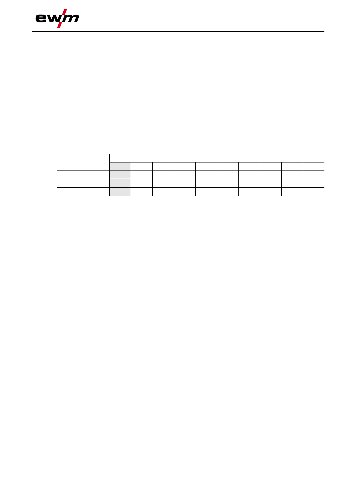
JOB no.
Display/selection on the accessory component
0 1 2 3 4 5 6 7 8
9
Special JOB 1
129
141
142
143
144
145
146
147
148
149
Special JOB 2
130
151
152
153
154
155
156
157
158
159
Special JOB 3
131
161
162
163
164
165
166
167
168
169
Block JOB mode (P16)
The following accessory components support block JOB mode:
• Up/Down welding torch with one-digit 7-segment display (two keys)
Program 0 is always active in JOB 0 and program 1 in all other JOBs
In this operating mode, up to 30 JOBs (welding tasks) divided into three blocks can be called up with accessory components.
The following configurations must be carried out to use the block JOB operation:
• Set the “Program or Up/Down function” changeover switch to “Program”
• Set the JOB list to actual JOB list (special parameter P12 = “1”)
• Enable block JOB mode (special parameter P16 = “1”)
• Switch to block JOB mode by selecting one of the special JOBs 129, 130 or 131.
Simultaneous operation with interfaces such as RINT X11, BUSINT X11, DVINT X11 or digital
accessory components like the R40 remote control is not possible!
Allocation of JOB numbers to the display on the accessory components
JOB 0:
This JOB allows you to set the welding parameters manually.
Selection of JOB 0 can be prevented via the key switch or with the "block program 0" parameter (P2).
Key switch position 0, or special parameter P2 = 0: JOB 0 is blocked.
Key switch position 1, or special parameter P2 = 1: JOB 0 can be selected.
JOBs 1-9:
Nine JOBs can be called up in each special JOB (see table).
Nominal values for wire speed, arc correction, dynamics etc must be defined in advance in these JOBs.
This can be done easily with the PC300.NETsoftware.
If the software is not available, user-defined JOB lists can be created in the special JOB areas with the
"Copy to" function. (See explanations about this in the "Switching JOB lists (P12)" chapter)
Selecting programs with the standard torch trigger (P17)
Allows you to select a program or switch a program before starting welding.
You switch to the next program by tapping the torch trigger. Once the last enabled program is reached,
you start again at the beginning.
• Program 0 is the first enabled program, provided that it is not blocked.
(see also special parameter P2).
• The last enabled program is P15.
- If the programs are not limited by special parameter P4 (see special parameter P4).
- Or if the programs are limited for the selected JOB by the n cycle setting (see parameter P8).
• Welding starts when the torch trigger is held for longer than 0.64 s.
You can select programs with the standard torch trigger in all operating modes (non-latched, special nonlatched. latched and special latched).
Program settings for relative programs (P23)
The start, down-slope and end program relative programs can be set individually or combined for the P0P15 operating points. When choosing the combined setting, in contrast to the individual setting, the parameter values are saved in the JOB With the individual setting, the parameter values are identical for all
JOBs (except for special JOBs and SP1, SP2 und SP3).
Nominal value wire heater (P26)
Preheating the welding wire in the temperature range of 25°C - 50°C. Setting 45°C ex works.
Page 30

Operating the machine control
Machine configuration (system)
30
099-00L105-EW501
07.06.2019
Menu item / parameter
Value
Comment
Operation without wire feeder is possible
(This parameter controls the system
behaviour depending on the connected
wire feeder)
No (factory
setting)
The wire feeder (WF) can be changed during
operation.
Operation without a connected wire feeder is
not possible.
Yes
The welding system can be operated without a
wire feeder connected.
Operating mode switching at welding start (P27)
With the selected 4-cycle-Special mode, the user can determine by the time of the torch trigger operation
in which operating mode (4-cycle or 4-cycle-Special) the program sequence shall be carried out.
Hold torch trigger (longer than 300 ms): Program sequence with operating mode 4-cycle-Special (standard).
Tap torch trigger: Device changes to operating mode 4-cycle.
Error threshold of electronic gas flow control (P28)
The set percentage value is the error threshold; if it is undershot or exceeded, an error messa-
5.4.5 Control
ge > see 7.3 chapter is displayed.
Page 31
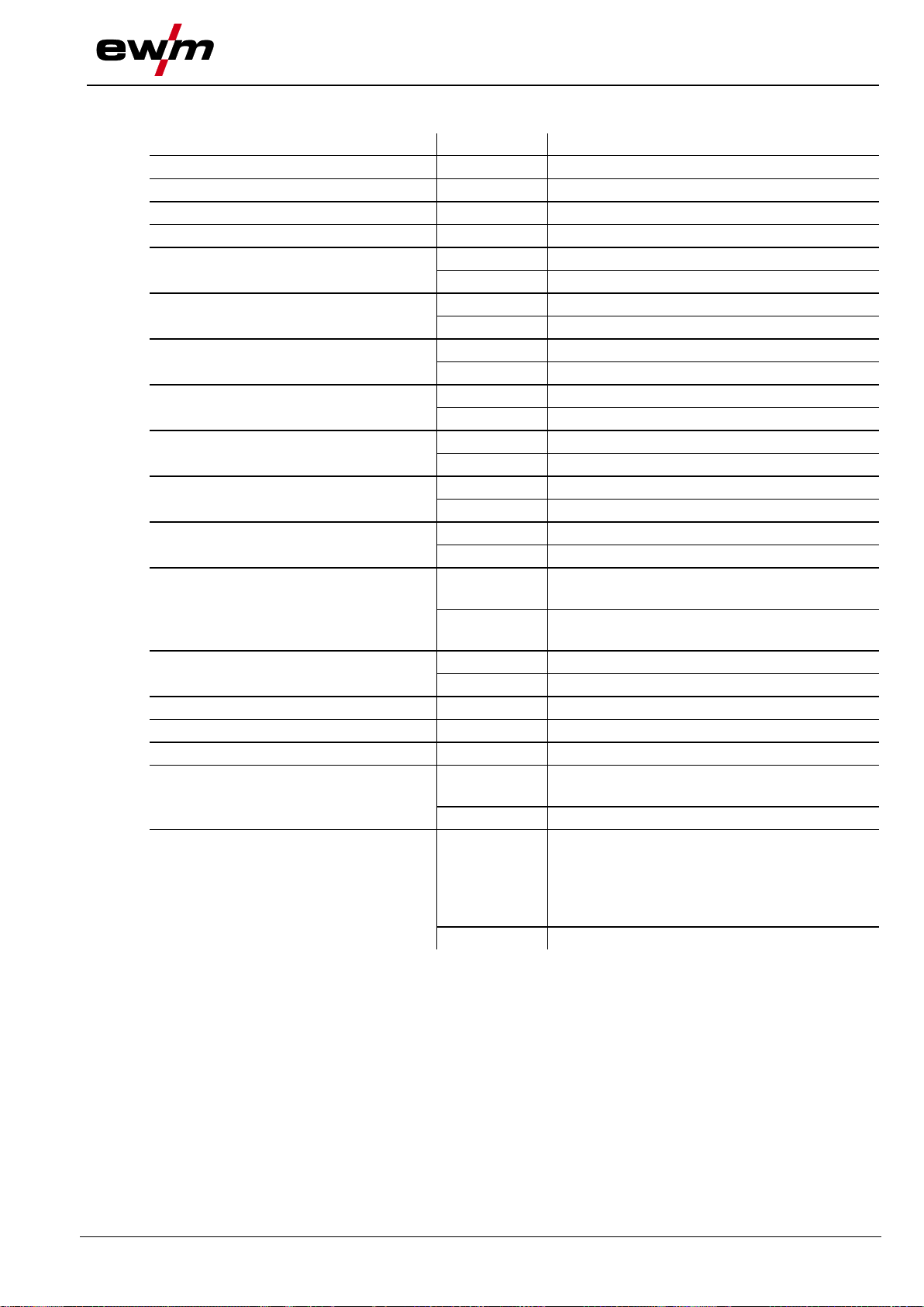
Operating the machine control
Machine configuration (system)
099-00L105-EW501
07.06.2019
31
Menu item / parameter
Value
Comment
Type of main screen
1-3 - Automatic selection of welding power
Off–30 s
-
Display brightness:
0-100 %
-
Display contrast:
0-100 %
-
Display negative:
No
-
Yes
-
Non-latched selectable
No -
Yes
-
Latched selectable
No
-
Yes
-
Special non-latched selectable
No
-
Yes
-
Spot welding selectable
No -
Yes
-
Special latched selectable
No
-
Yes
-
P0 of Expert XQ 2.0 can be changed:
No
-
Yes
-
Mean value display for superPuls:
Yes
When superPuls is enabled the welding power
is displayed as average value.
No
The welding power is displayed by program A
even when superPuls is enabled.
Hold function:
On
-
Off - Language
German
-
Measuring units
Metric
- Imperial
-
Numbering files consecutively
Yes
The file names are numbered consecutively
when saving.
No
One file is always overwritten.
Expert XQ 2.0 reset to factory settings
Yes
Only those parameters relevant for Expert XQ 2.0 (e.g. display settings and languages) will be reset. This does not affect system
parameters such as Xbutton - activation or
JOBs.
No
-
5.4.6 Operating panel settings
Page 32

Operating the machine control
Machine configuration (system)
32
099-00L105-EW501
07.06.2019
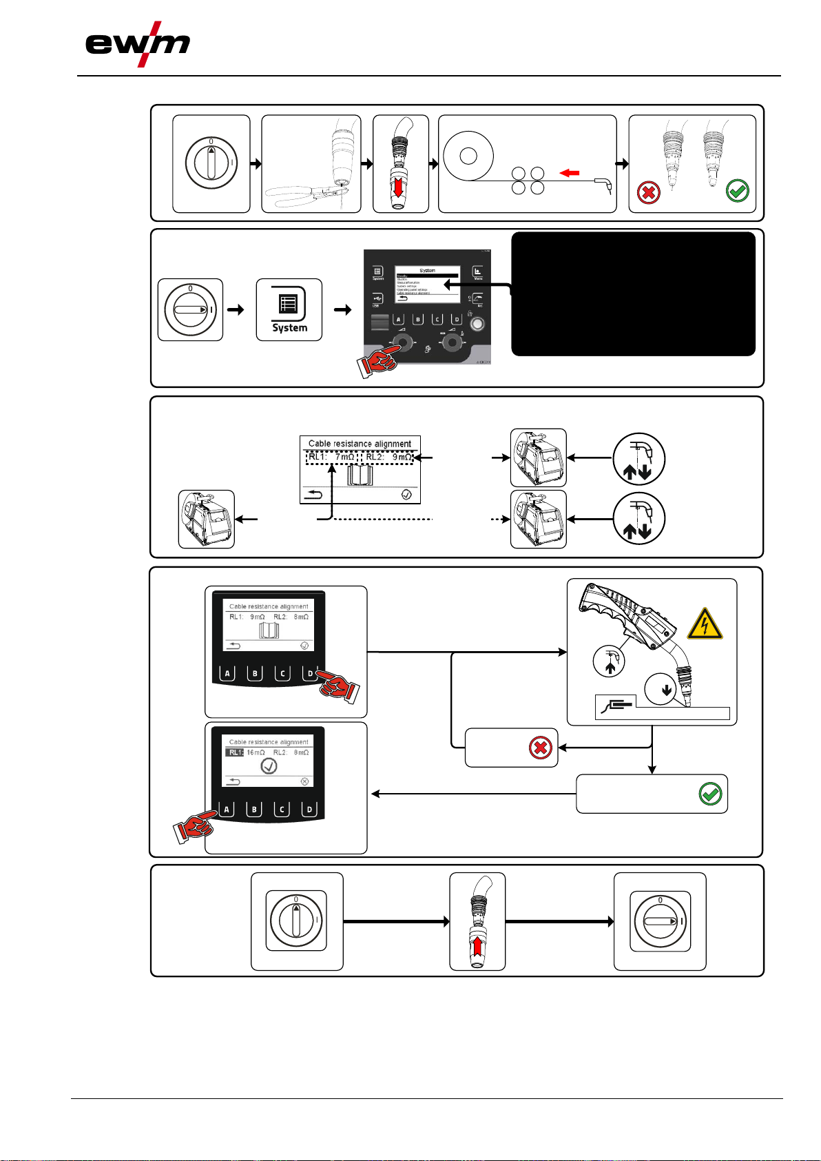
5.4.7 Aligning the cable resistance
The resistance value of cables can either be set directly or it can be aligned using the power source. The
factory setting of the power sources is 8 mΩ. This value correponds to a 5 m earth cable, a 1.5 m intermediate hose package and a 3 m water-cooled welding torch. With other hose package lengths, it is necessary to carry out a +/- voltage correction to optimise welding properties. The voltage correction value
can be set close to zero by means of realigning the cable resistance. It is recommended to align the
electric cable resistance after replacing accessories such as torches or intermediate hose packages.
In case a second wire feeder is used the (rL2) parameter has to be aligned. For all other configurations it
is sufficient to align the (rL1) parameter.
1 Preparation
• Switch off the welding machine.
• Unscrew the gas nozzle from the welding torch.
• Trim the welding wire so that it is flush with the contact tip.
• Pull the welding wire back a little (about 50 mm) on the wire feeder (by pressing button B - wire return). There should be no more welding wire in the contact tip at this point.
2 Configuration
• Switch on the welding machine
• Press the "System" push-button.
• Select the "Cable resistance alignment" parameter using the main control button. Parameter RL1 must
be aligned for all machine combinations. In case of welding systems with a second power circuit – if
two wire feeders are to be operated from a single power source, for example – a second alignment
with parameter RL2 must be made. To activate the required wire feeder for measurement, briefly activate (tap) the torch trigger of this machine.
3 Alignment / Measurement
• Press the "D" push-button.
• Place the welding torch with the contact tip on a clean spot of the workpiece with a little pressure and
press the torch trigger for approx. 2 seconds. A short-circuit current will flow briefly, which is used to
determine and display the cable resistance. The value can be between 0 mΩ and 40 mΩ. The new value is immediately saved without requiring further confirmation. If no value is shown on the display,
then the measurement failed. The measurement must be repeated.
• Press the "A" push-button after successful measurement.
4 Restoring welding standby mode
• Switch off the welding machine.
• Screw the gas nozzle onto the welding torch.
• Switch on the welding machine.
• Insert the welding wire again.
Page 33
Operating the machine control
Machine configuration (system)
099-00L105-EW501
07.06.2019
33
3
4
2
5
1
l0l
0
DE - Abgleich Leitungswiderstand
EN - Cable resistance alignment
FR - Alignement résistance ligne
IT - Compensazione resistenza circuito
ES - Compensación de la resistencia del cable
NL - Compensatie leidingsweerstand
SE - Kalibrering av ledningsmotståndet
PL - Porównanie rezystancji przewodu
RU - Компенсация сопротивления проводника
50mm
WF 1 = RL1
WF 2 = RL2
Press torch
trigger to
activate the
respective WF
WF 1 = RL1
B
A
start = D
0mΩ - 40mΩ
end = A
__mΩ
System with 1 WF System with 2 WF
Figure 5-7
Page 34

Operating the machine control
Machine configuration (system)
34
099-00L105-EW501
07.06.2019
Item
Symbol
Description 0
1
QR code
2
Menu navigation
Skip back to previous menu
3
Reset message
The message can be reset and a new QR code may be requested from the network.
Item
Symbol
Description 0
1
Component data
2
Menu navigation
Skip back to previous menu
3
Reset message
The message can be reset
Item
Symbol
Description 0
1
Component data
2
Menu navigation
Skip back to previous menu
5.4.8 Xnet machine
The Xnet machine defines the system component required for operating the Xnet system as part of the
Expert 2.0 Net/Gateway to connect to power sources or to record welding data.
5.4.8.1 Coupling mobile machines
QR code for coupling mobile end devices. Upon a successful connection, welding data are displayed on
the end device.
5.4.8.2 Component identification
Bar codes predefined in ewm Xnet are recorded with a manual scanner. Component data are retrieved
and displayed in the control.
Figure 5-8
5.4.8.3 Component details
Figure 5-9
Figure 5-10
Page 35
Operating the machine control
Offline data transfer (USB)
099-00L105-EW501
07.06.2019
35
5.4.8.4 Errors and warnings
A list of all ewm Xnet-specific errors and warnings are displayed with their ID number and description.
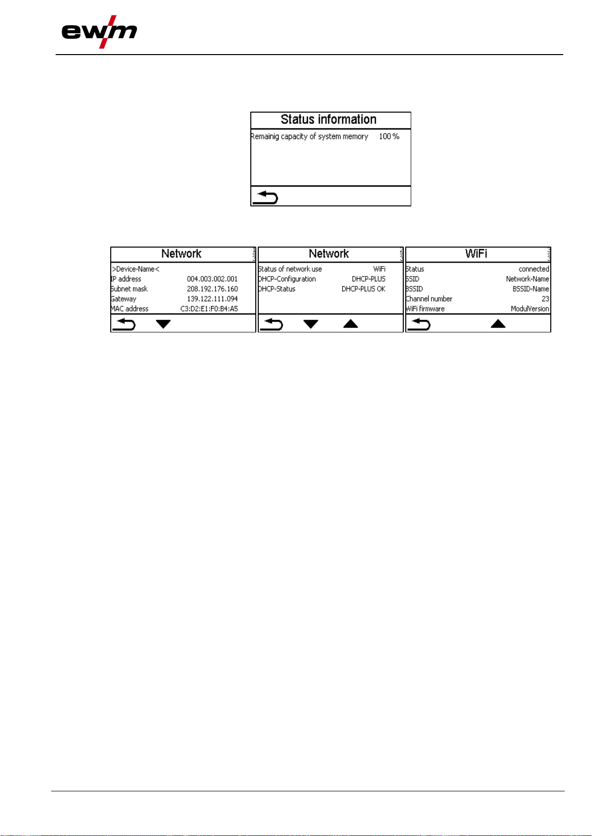
5.4.8.5 Status information
5.4.8.6 Network
5.4.8.7 Clear system memory
Resets the internal system memory used for saving welding and log data and deletes all data.
All welding data recorded so far, which have not been transferred to the Xnet server via flash
drive or network connection, will be permanently deleted.
5.4.8.8 Reset to factory settings
All machine configuration data relating to Xnet will be reset to the factory setting. The system memory data will not be affected, i.e. any welding or log data recorded will be saved.
Figure 5-11
Figure 5-12
Page 36
Operating the machine control
Offline data transfer (USB)
36
099-00L105-EW501
07.06.2019
You may only use this USB interface to exchange data with a USB flash memory. You must not
connect any other USB devices such as keyboards, hard disks, mobile telephones, cameras or
other devices so as to avoid any damage tp the machine. The interface does not provide any load
functions either.
5.5 Offline data transfer (USB)
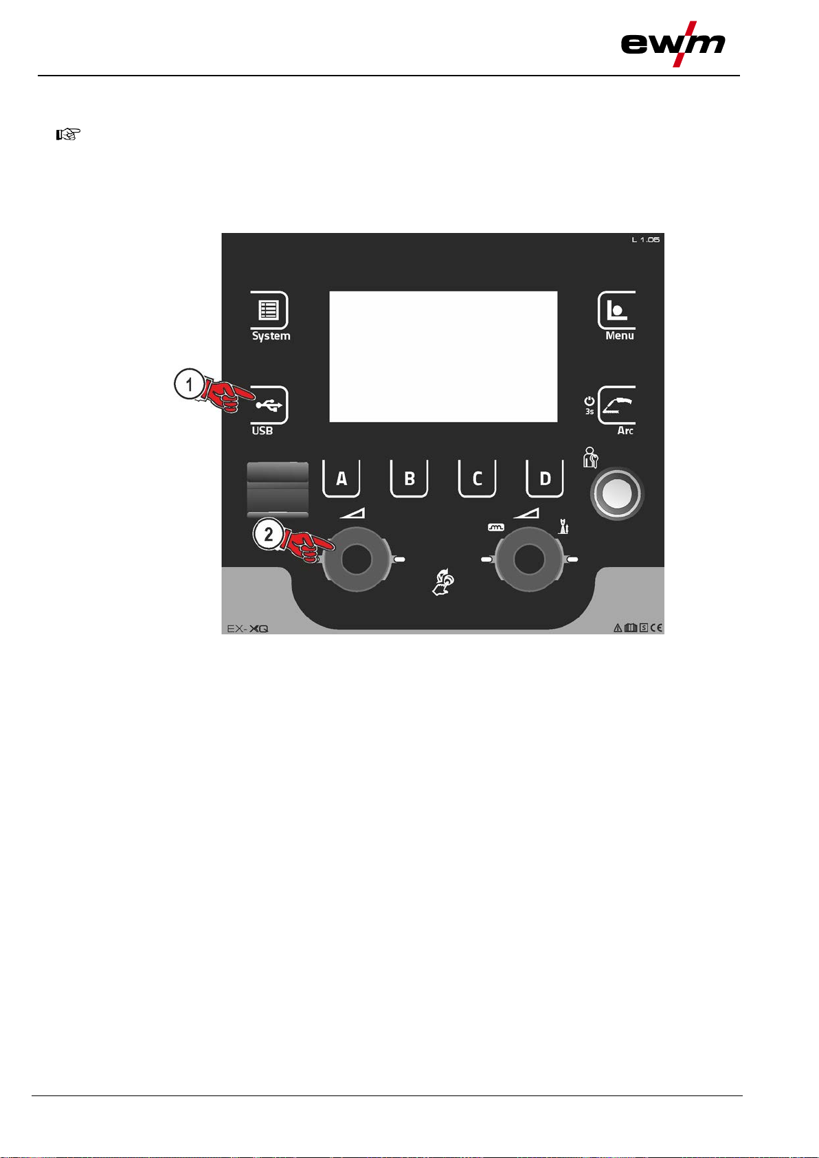
Using the USB interface, data can be transferred between the machine control and a USB storage medium.
5.5.1 Save JOB(s)
Saving a single (JOB) or a range of welding tasks (JOB)s) (from–to) from the welding machine to the storage media (USB).
5.5.2 Load JOB(s)
Loading a single JOB or a range of welding tasks (JOBs) (from–to) from the storage media (USB) to the
welding machine.
5.5.3 Save configuration
5.5.3.1 System
Configuration data of the power source’s system components.
5.5.3.2 Xnet machine Master configuration
Core date for network communication (independent of machine).
Individual configuration
Machine-related configuration data, matching the current power source only.
Figure 5-13
Page 37

Operating the machine control
Offline data transfer (USB)
099-00L105-EW501
07.06.2019
37
5.5.4 Load configuration
5.5.4.1 System
Configuration data of the power source’s system components.
5.5.4.2 Xnet machine Master configuration
Core date for network communication (independent of machine).
Individual configuration
Machine-related configuration data, matching the current power source only.
5.5.5 Load languages and texts
Load a language and text package from the storage medium (USB) to the welding machine.
5.5.6 Record on USB drive
You can record welding data on a storage medium and read or analyse them using the Xnet quality management software when required. For machine variants with network capability (LG/WLG) only!
5.5.6.1 Register USB drive
To identify and allocate the welding data between power source and storage medium the storage medium
has to be registered once. This is done by selecting the menu option "Register USB drive" or by starting a
data recording process. Successful registration is indicated by a checkmark next to the relevant menu option.
If the storage medium is registered and connected when the power source is being switched on, recording of the welding data starts automatically.
5.5.6.2 Start recording
After confirming the start of data recording the storage medium will be registered (if not registered yet).
Data recording starts and is indicated at the main screen by a slow flashing of the icon.
5.5.6.3 Stop recording
To avoid data loss, finish the recording with this menu option before removing the USB drive or switching
off the machine.
Welding data must be imported into the Xnet quality management software using the XWDImport
software. This software is an integral part of the Xnet installation.
Page 38
Operating the machine control
Welding task administration (Menu)
38
099-00L105-EW501
07.06.2019
5.6 Welding task administration (Menu)
In this menu the user can carry out all welding task (JOB) organisation operations.
This machine series offers user-friendly operation and a multitude of features.
• Various welding tasks (JOBs) consisting of welding procedure, material type, wire diameter and shiel-
ding gas type have been predefined > see 8.2 chapter.
• The system calculates the required process parameters depending on the operating point specified
(one-knob operation via wire feed speed rotary transducer).
• You can adjust additional parameters at the machine control or using the PC300.NET welding parameter software, if required.
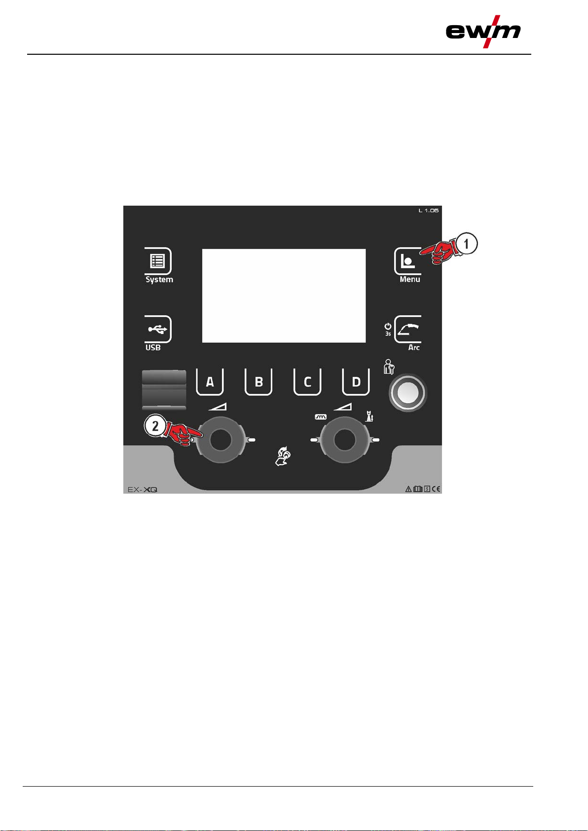
Enter the menu:
5.6.1 JOB selection (material/wire/gas)
The welding task (JOB) can be set in two ways:
a) Enter the relevant JOB number. Each welding task has a unique JOB number (for predefined
JOBs > see 8.2 chapter , see the JOB list in the annex or the sticker on the machine).
b) Enter the basic welding parameters: welding procedure, material type, wire diameter and shielding gas
type.
Figure 5-14
Page 39

Operating the machine control
Welding task administration (Menu)
099-00L105-EW501
07.06.2019
39
Item
Symbol
Description 0
1
Status of Favourites
--------- Favourite loaded, settings of the Favourite and the current device settings are
identical
--------- Favourite loaded, but settings of the Favourite and the current device settings
are not identical (e.g. operating point has been changed)
--------- Favourite not loaded (e.g. JOB number has been changed)
2
Location number of the Favourite
3
Display of the welding task (JOB)
Displays the JOB number assigned to the Favourites location (setting “---” means: no
JOB assigned)
4
Display of the program (P0-P15)
Display of the program number assigned to the Favourite location
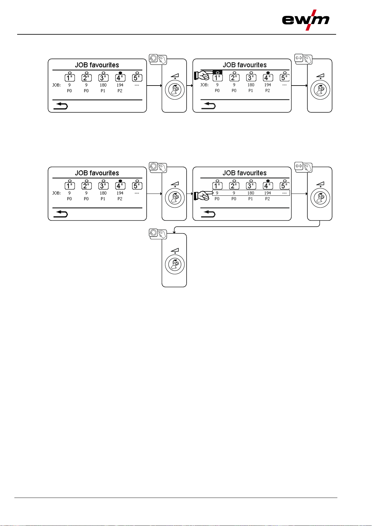
5.6.2 JOB favourites
Favourites are additional locations for storing and loading frequently used welding tasks, programs and
their settings. The status of the Favourites (loaded, changed, not loaded) is indicated by signal lights.
• Five Favourites are available to save any settings.
• As required, the access control can be adjusted with the key switch or Xbutton function.
Figure 5-15
5.6.2.1 Saving current settings to Favourites
• Use the click wheel welding power to switch to the desired Favourite (JOB line).
• Press the click wheel to confirm the current settings in this location.
Figure 5-16
Page 40
Operating the machine control
Welding task administration (Menu)
40
099-00L105-EW501
07.06.2019
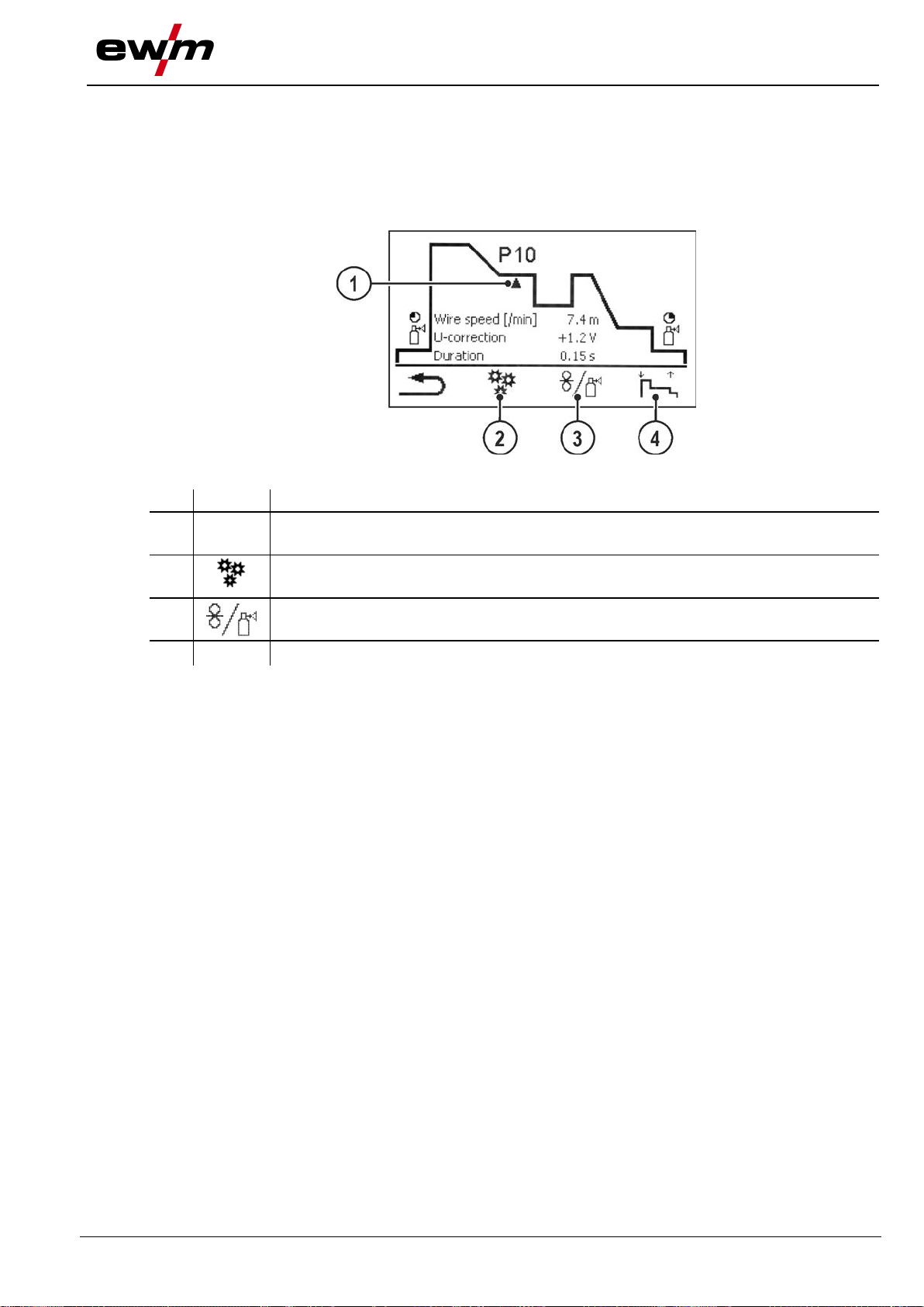
5.6.2.2 Loading saved Favourites
• Use the click wheel welding power to switch to the desired Favourite (“Status Favourite” line).
• Press the click wheel to load the appropriate Favourite.
5.6.2.3 Deleting saved Favourites
Figure 5-17
• Turn the click wheel welding power to switch to the desired Favourite (JOB line).
• Press the click wheel to confirm the selection of the appropriate Favourite.
• Turn the click wheel to the left to delete the Favourite (indicated by three hyphens “---”)
5.6.3 JOB manager
5.6.3.1 Copy JOB to number
Copy JOB to a number of the definable range (129–169).
5.6.3.2 Reset current JOB
Reset all parameters of the selected JOB to the factory setting
5.6.3.3 Reset all JOBs
Reset all JOBs to the factory setting, except JOBs in the definable range (129–169) > see 7.4 chapter.
Figure 5-18
Page 41
Operating the machine control
Welding task administration (Menu)
099-00L105-EW501
07.06.2019
41
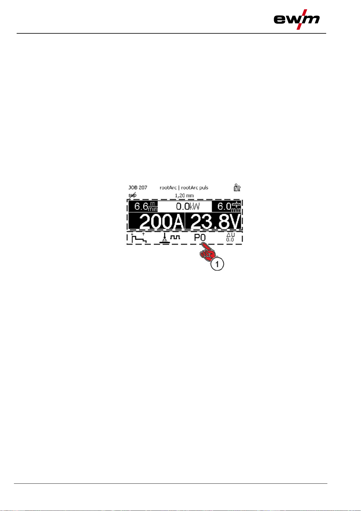
Item
Symbol
Description 0
1
▲
Parameter position
Displays the currently selected welding parameters in the functional sequence
2
Advanced settings
Display and setting of advanced process parameters
3
Setup mode > see 5.6.6 chapter
4
Operating mode setting
5.6.4 Program sequence
In the program sequence, you can select welding parameters and set their values. The number of parameters shown depends on the selected operating mode.
In addition, the user can access advanced settings and the setup mode.
The setting range for the parameter values are summarised in the parameter overview
section > see 8.1 chapter.
Figure 5-19
Page 42
Operating the machine control
Welding task administration (Menu)
42
099-00L105-EW501
07.06.2019
5.6.5 Programs (PA 1-15)
In the manual program P0, the user can adjust the operating point in a conventional way using the parameter settings on the machine control. The active program is shown in the main menu of the machine
display in the display area for process parameters with the letter “P” and the corresponding program
number.
Different welding tasks or positions on a workpiece require different welding power values (operating
points) or parameter settings. These settings can be stored in up to 15 programs (P1 to P15) and recalled, as needed, at the machine control or a suitable accessory component (e.g. welding torch).
Welding parameters for program 0 (P0) are changed for decompact machine systems at the machine
control of the wire feeder (factory setting). To change the parameters using the Expert 2.0 machine con-
trol, the parameter “P0 changeable by Expert 2.0“ must be set to “Yes” > see 5.4.6 chapter.
Welding parameters for programs 1 - 15 can be changed on any control connected in the system.
The following parameters and their values are stored in each program:
• Wire feed speed and voltage correction (welding power)
• Operating mode, welding type, dynamics and setting superPuls
Changes to the parameter settings are stored in the selected program without further prompt.
Selection
Figure 5-20
Page 43

Operating the machine control
Welding task administration (Menu)
099-00L105-EW501
07.06.2019
43
Program switching
JOB switching
Process
switching
Welding type
Program
Operating mode
Wire feed speed
Voltage correction
Dynamics
M3.7 – I/J
Wire feeder control
P0
P1-15
PC 300.NET
Software
P0
P1-15
MT Up/Down
Welding torch
P0
P1-9
MT 2 Up/Down
Welding torch
P0
P1-15
MT PC 1
Welding torch
P0
P1-15
MT PC 2
Welding torch
P0
P1-15
PM 2 Up/Down
Welding torch
P0
P1-15
PM RD 2
Welding torch
P0
P1-15
PM RD 3
Welding torch
P0
P1-15
5.6.5.1 Overview of the welding parameter switching options
The user can change the welding parameters of the main programs with the following components.
Example 1: Welding workpieces with different sheet metal thicknesses (non-latched)
Figure 5-21
Page 44
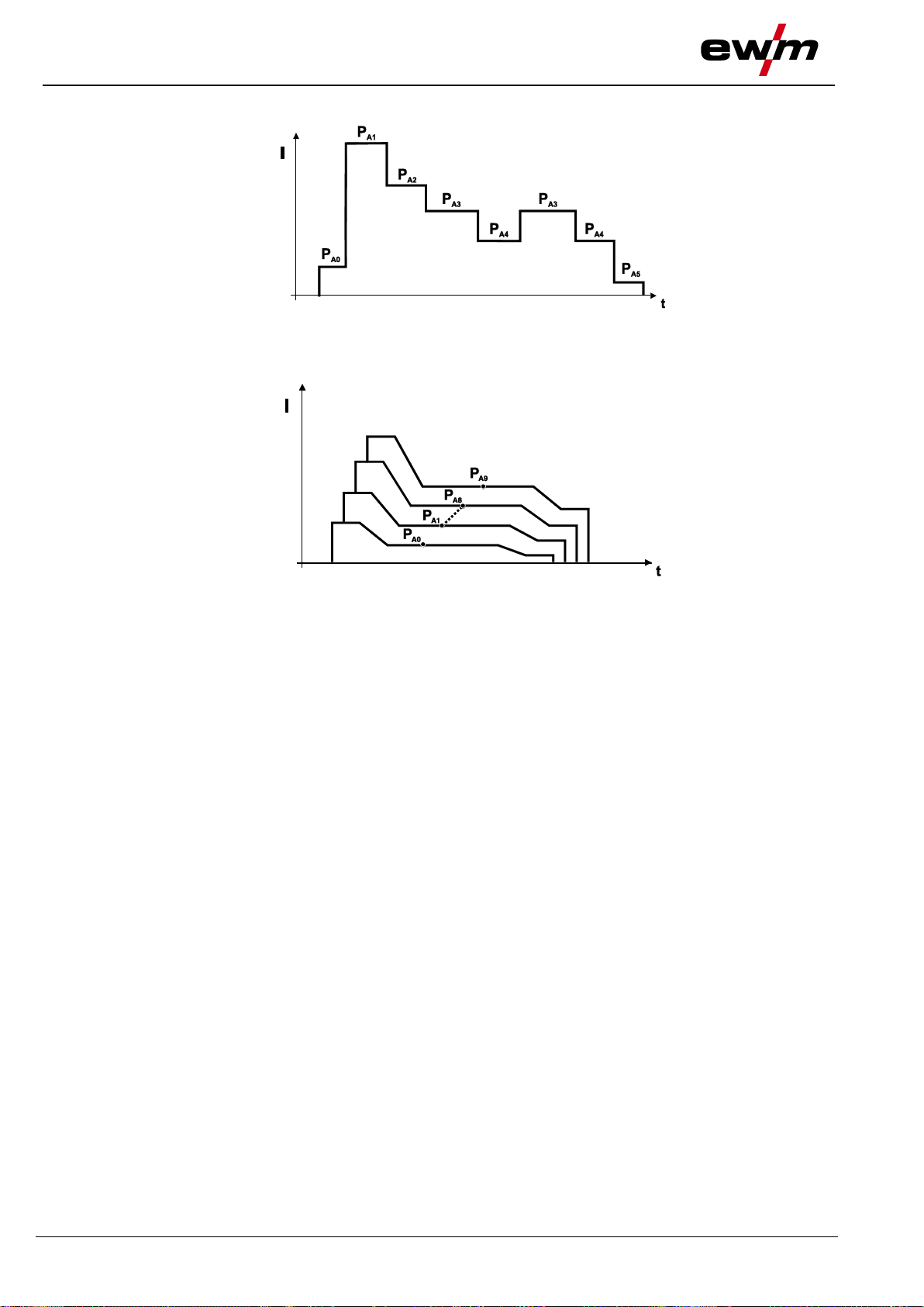
Operating the machine control
Welding task administration (Menu)
44
099-00L105-EW501
07.06.2019
Example 2: Welding different positions on a workpiece (latched)
Figure 5-22
Example 3: Aluminium welding of different sheet metal thicknesses (non-latched or latched
special)
Figure 5-23
Page 45

Operating the machine control
Welding task administration (Menu)
099-00L105-EW501
07.06.2019
45
Menu item/parameter
Program
Comment
Gas pre-flow time
Gas nominal value
GFE option/variant (electronic gas volume control) required
WF relative
P
START
Wire feed speed, relative
Duration
Duration (start program)
U correction
Arc length correction
Slope time
Slope duration from P
START
to PA
WF (/min.)
PA
Wire feed speed, absolute
U correction
Arc length correction
Duration
Duration (spot time and superPuls time)
Slope time
Slope duration from PA to PB
WF relative
PB
Wire feed speed, relative
Duration
Duration (reduced main program)
U correction
Arc length correction, relative
Slope time
Slope duration from PB to PA
Slope time
Slope duration from PB to P
END
WF relative
P
END
Wire feed speed, relative
Duration
Duration (end program)
U correction
Arc length correction, relative
Wire burn-back
Gas post-flow time
5.6.5.2 MIG/MAG welding
In every JOB, separate settings can be made for the ignition program, reduced main program and end
program as to whether or not to alternate with the pulse process.
These properties are stored on the welding machine with the JOB. This means that in the factory settings,
the pulse process is active during the end program in all forceArc JOBs.
P
, PB and P
START
END
feed value of the main program PA. These programs can also be configured using absolute values,
if desired (see Absolute value set point). > see 5.6.9 chapter.
Figure 5-24
are set as relative programs ex factory. They relate to percentages of the wire
Page 46
Operating the machine control
Welding task administration (Menu)
46
099-00L105-EW501
07.06.2019
Menu item/parameter
Value
Comment
Process switching
Off
On
Start program pulsing
Off
On
End program pulsing
Off
On
Wire retraction ignition
Off
Lift arc (PP)
Lift arc
End pulse duration
0.0–20 ms
U correction limit
0.0–9.9 V
Applies with correction operation enabled
Wire correction limit
0–30%
N cycle program limit
Off
1-15
Slope between programs (/100 ms)
Off
0.1–2.0 m/min
waveArc
Off
On
5.6.5.3 Advanced settings
Page 47
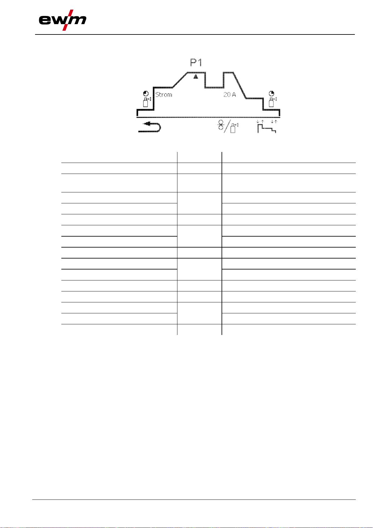
Operating the machine control
Welding task administration (Menu)
099-00L105-EW501
07.06.2019
47
Menu item/parameter
Program
Comment
Gas pre-flow time
Gas nominal value
GFE option/variant (electronic gas volume control) required
Current
P
START
Ignition current
Duration
Duration (start program)
Slope time
Slope duration from P
START
to PA
Current
PA
Welding current, absolute
Duration
Pulse time (superPuls)
Slope time
Slope duration from PA to PB
Current
PB
Welding current
Duration
Pulse pause time (superPuls)
Slope time
Slope duration from PB to PA
Slope time
Slope duration from PA to P
END
Current
P
END
Welding current
Duration
Gas post-flow time
5.6.5.4 TIG welding
Figure 5-25
Page 48
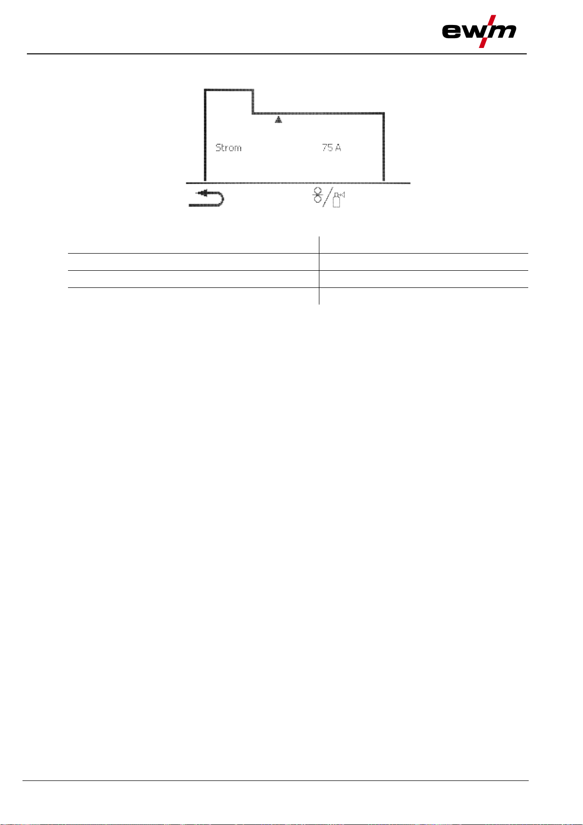
Operating the machine control
Welding task administration (Menu)
48
099-00L105-EW501
07.06.2019
Menu item/parameter
Comment
Current
Hot start current
Duration
Hot start time
Current
Main current
5.6.5.5 MMA welding
The hotstart current is a percentage based on the welding current selected.
Figure 5-26
Page 49

Operating the machine control
Welding task administration (Menu)
099-00L105-EW501
07.06.2019
49
Item
Symbol
Description 0
1
Wire return
Results in reverse inching of the wire. Pressing the push-button longer will increase the
wire reversing speed.
2
Wire inching
The wire is inched into the hose package. Pressing the push-button longer will increase
the wire inching speed.
3
Push-button, gas test/purge hose package
• ----------- Gas test:
Shielding gas (symbol flashes slowly) will flow for approximately 20 seconds
after pressing the push-button once. Press the button again to cancel the
process early.
• ----------- Purge hose package:
Press push-button for about 5 sec: Shielding gas flows permanently (mac 300
s) until the Gas test push-button is pressed again (shielding gas flashes fast).
Menu item/parameter
Value
Comment
WF nominal value
0.0 m/min
only if the control is integrated in the wire feeder
WF actual value
0.0 m/min
Motor current
0.0 A
Gas nominal value
0.0 l/min
GFE option/variant (electronic
gas volume control) required
Gas flow
0.0 l/min
5.6.6 Setup mode
Figure 5-27
All functions run without current (set-up phase). This provides a high degree of safety for the welder,
since the arc cannot be inadvertently ignited. The following parameters can be monitored during the wire
configuration:
Page 50

Operating the machine control
Welding task administration (Menu)
50
099-00L105-EW501
07.06.2019
Menu item/parameter
Value
Comment
Weld length:
1.0-999.9 cm
Welding speed:
1.0-
999.9 cm/min.
Thermal efficiency:
10-100%
Heat input:
kJ/mm
Preheating temperature:
0-499 °C
Material thickness:
1.0-999.9 mm
Weld seam factor:
0.01-1.5
Transition thickness:
mm t8/5-time:
s
5.6.7 WPQR welding data assistant
The cooling-down time from 800°C to 500°C essential for the welding result (known also as t8/5 time) can
be calculated using the input data in the WPQR welding data assistant. Prerequisite is the prior determination of the heat input. Upon input of the values, the valid t8/5 time is displayed with a black background.
Page 51
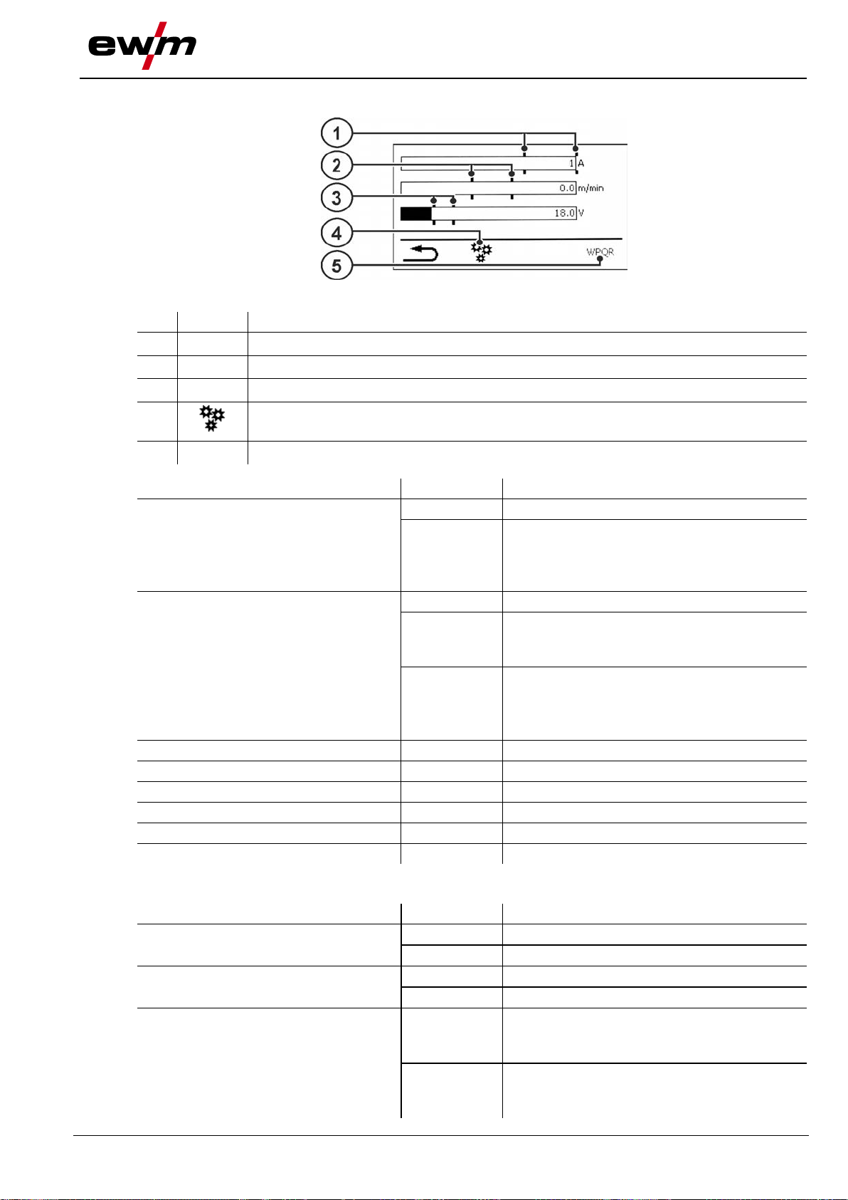
Operating the machine control
Welding task administration (Menu)
099-00L105-EW501
07.06.2019
51
Item
Symbol
Description 0
1
Current tolerance
2
WF tolerance
3
Voltage tolerance
4
Advanced settings
Display and setting of advanced system parameters
5
WPQR
WPQR welding data assistant
Menu item / parameter
Value
Comment
Automatic
No
Yes
The welding monitoring window opens automatically from the main screen after a welding
start. A rotary knob actuation automatically
switches back to the main window.
Errors and warnings
Off
Warnings
Exceeding a tolerance limit for the duration of
the tolerance response time triggers warning
12.
Error
Exceeding a tolerance limit for the duration of
the tolerance response time triggers error 61.
Please note: Error leads to immediate stop of
the ongoing welding!
Voltage tolerance
0-100 %
Current tolerance
0-100 %
Tolerance response time
0.00-20.0 s
For voltage and current tolerance
Wire feeder tolerance
0-100 %
Maximum permissible motor current
0.0-5.0 A
Tolerance response time
0.00-20.0 s
For WF tolerance and motor current
Menu item/parameter
Value
Comment
Text for material:
Standard
Alternative
Text for gas:
Standard
Alternative
Absolute value set point:
Yes
Ignition current, secondary current and end
current are set and displayed as absolute values
No
Ignition current, secondary current and end
current are defined and displayed as a percentage of program A (ex works)
5.6.8 Welding monitoring
Figure 5-28
5.6.9 JOB display setting
Page 52
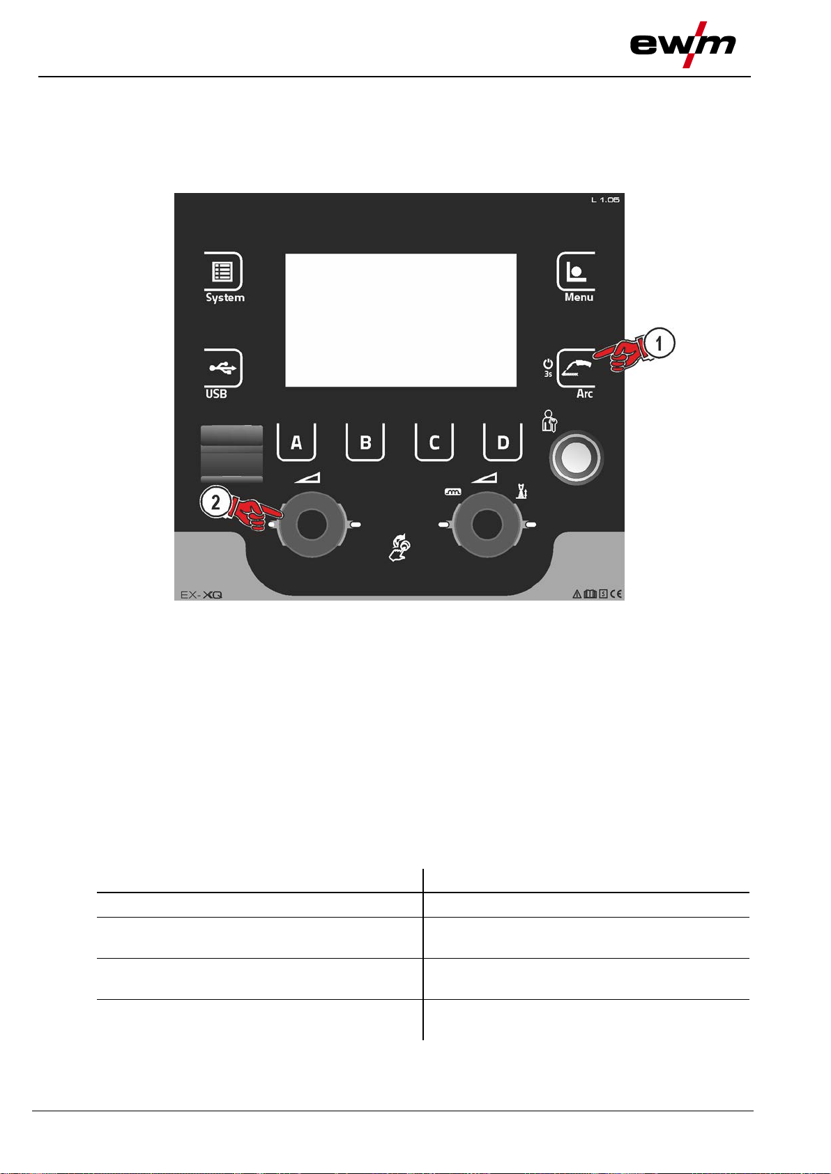
Operating the machine control
Change welding procedure (Arc)
52
099-00L105-EW501
07.06.2019
Status description
Status display
No physical connection to a network
Deactivated LAN symbol
Connection to the network, the machine has been
configured, no data transfer
Activated LAN symbol
Connection to the network, the machine has been
configured and transfers data
LAN symbol flashing
Connection to the network, the machine has been
configured and tries to connect to the data server
LAN symbol flashing in the specified rhythm
5.7 Change welding procedure (Arc)
In this menu the user can change the welding procedure based on the preselected material, wire and gas
(change of process based on welding task).
For changing the welding task (JOB) > see 5.6 chapter
Enter the menu:
5.8 Online data transfer (network)
For machine variants with network capability (LG/WLG) only!
The network is used to transfer welding data from manual, automated and welding machines. It can include as many welding machines and computers as require and the collected data can be retrieved from
one or several server PCs.
The Xnet software allows the user to monitor all welding parameters in real time and/or to subsequently
analyse the saved welding data. The results can be used for process optimisation, welding calculations or
checking welding wire batches.
Depending on the welding machine the data are transferred to the server via LAN/WiFi and can then be
accessed in a browser window. The user interface and web-based design of the software offer the possi-
5.8.1 Wired local network (LAN)
bility to analyse and monitor the welding data via a tablet PC.
Figure 5-29
Page 53

Operating the machine control
Online data transfer (network)
099-00L105-EW501
07.06.2019
53
Status description
Status display
No physical connection to a network
Deactivated WiFi symbol
Connection to a network, no data transfer
Activated WiFi symbol
Connection to a network, transferring data
WiFi symbol flashing
Connection to the network, the machine has been
configured and tries to connect to the data server
LAN symbol flashing in the specified rhythm
5.8.2 Wireless local network (WiFi)
Page 54

Welding procedure
MIG/MAG welding
54
099-00L105-EW501
07.06.2019
6 Welding procedure
The welding task is selected in the JOB selection menu (material/wire/gas) > see 5.6.1 chapter.
The basic settings of the relevant welding procedure, such as operating mode or arc length correction,
can be selected on the main screen on the process parameter panel > see 4.3.2 chapter.
6.1 MIG/MAG welding
6.1.1 Welding type
6.1.1.1 Welding power (operating point)
6.1.1.2 Accessory components for operating point setting
6.1.1.3 Arc length
6.1.1.4 Arc dynamics (choke effect)
The program sequence settings are set in the program sequence menu > see 5.6.4 chapter.
Different forms of MIG/MAG processes are referred to as welding type.
Standard (Welding with standard arc)
Depending on the set combination of wire feed speed and arc voltage, the arc types short arc, transitional
arc or spray arc can be used for welding.
Pulse (Welding with pulsed arc)
A targeted change in the welding current generates current pulses in the arc, which lead to a 1 drop per
pulse of material transfer. The result is an almost spatter-free process, suitable for welding of all materials, in particular high-alloy CrNi steels or aluminium.
Positionweld (Positional welding)
A combination of the pulse/standard or pulse/pulse welding types, which is particularly suitable for positional welding due to factory-optimized parameters.
The welding power is adjusted according to the principle of one-knob operation. The user can set their
operating point optionally as wire feed speed, welding current or material thickness. The optimum welding
voltage for the operating point is calculated and set by the welding machine. If necessary, the user can
correct this welding voltage > see 6.1.1.3 chapter.
Application example (setting via material thickness)
The required wire feed speed is not known and is to be determined.
• Select welding task JOB 76( > see 5.6 chapter): material = AlMg, gas = Ar 100%, wire diameter =
1.2 mm.
• Switch the display to material thickness.
• Measure the material thickness (workpiece).
• Set the measured value, e.g. 5 mm, at the machine control.
This set value corresponds to a specific wire feed speed. Switching the display to this parameter will
show the associated value.
In this example, a material thickness of 5 mm corresponds to a wire feed speed of 8.4 m/min.
The material thickness details in the welding programs generally refer to fillet welds in the PB welding position. They should be regarded as guideline values and may differ in other welding positions.
The operating point can be set at various accessory components as well, such as remote control, special
welding torches or robot and industrial bus interfaces (optional interface for automated welding required,
not available for all machines of this series).
See the operating instructions for the machine in question for a more detailed description of the individual
machines and their functions.
When required, the arc length (welding voltage) can be adjusted for the welding task in hand by +/– 9.9 V.
This function can be used to adjust the arc between a narrow, hard arc with deep penetration (positive values) and a wide and soft arc (negative values). In addition, the selected settings are displayed with signal
lights below the rotary knobs.
Page 55
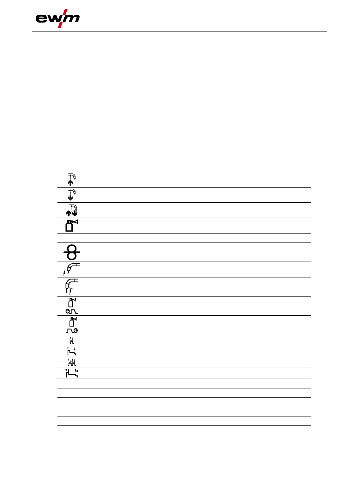
Welding procedure
MIG/MAG welding
099-00L105-EW501
07.06.2019
55
Symbol
Meaning
Press torch trigger
Release torch trigger
Tap torch trigger (press briefly and release)
Shielding gas flowing
I
Welding output
Wire electrode is being conveyed
Wire creep
Wire burn-back
Gas pre-flows
Gas post-flows
Non-latched
Special, non-latched
Latched
Special, latched
t
Time
P
START
Ignition program
PA
Main program
PB
Reduced main program
P
END
End program
t2
Spot time
6.1.1.5 superPuls
In superPuls mode, the program toggles between the main program (PA) and the reduced main program
(PB). This function is e.g. used for thin sheet welding to reduce the heat input in a controlled manner or
for positional welding without the need for weaving.
The combination of superPuls and other EWM welding processes offers a multitude of possibilities. For
example, to enable the welding of vertical-up welds without the "Christmas tree" technique, when selec-
ting program 1 > see 5.6.5 chapter the relevant superPuls variant (depending on the material) is activated
as well. The required superPuls parameters are defined ex works.
The welding power can be represented as average value (ex works) or solely as program A value. If the
average value display is activated the signal lights of the main (PA) and reduced main program (PB) are
illuminated simultaneously. The display variants can be toggled using special parameter
P19, > see 5.4.4.4 chapter.
6.1.2 Operating modes
There are optimum pre-sets for welding parameters such as gas pre-flow and burn back, etc. for
numerous applications (although these can also be changed if required).
6.1.2.1 Explanation of signs and functions
Page 56
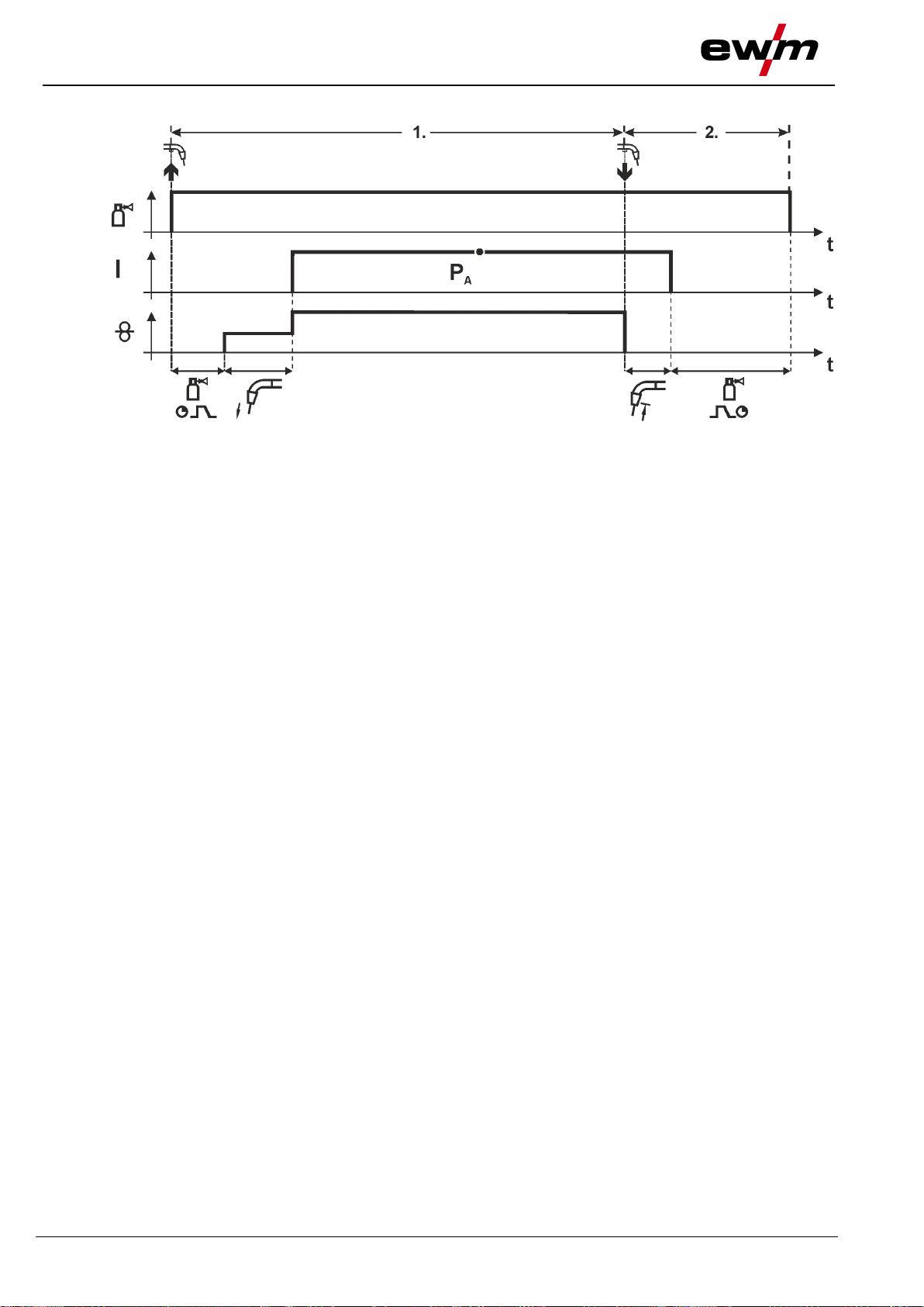
Welding procedure
MIG/MAG welding
56
099-00L105-EW501
07.06.2019
Non-latched mode
Figure 6-1
Step 1
• Press and hold torch trigger.
• Shielding gas is expelled (gas pre-flows).
• Wire feed motor runs at “creep speed”.
• Arc ignites after the wire electrode makes contact with the workpiece; welding current flows.
• Change over to pre-selected wire speed.
Step 2
• Release torch trigger.
• WF motor stops.
• Arc is extinguished after the preselected wire burn-back time expires.
• Gas post-flow time elapses.
Page 57

Welding procedure
MIG/MAG welding
099-00L105-EW501
07.06.2019
57
Non-latched operation with superpulse
Figure 6-2
Step 1
• Press and hold torch trigger.
• Shielding gas is expelled (gas pre-flows).
• Wire feed motor runs at “creep speed”.
• Arc ignites after the wire electrode makes contact with the workpiece; welding current flows.
• Start the super pulse function beginning with main program PA:
The welding parameters change at the specified times between main program PA and the reduced
main program PB.
Step 2
• Release torch trigger.
• Super pulse function is ended.
• WF motor stops.
• Arc is extinguished after the preselected wire burn-back time expires.
• Gas post-flow time elapses.
Page 58
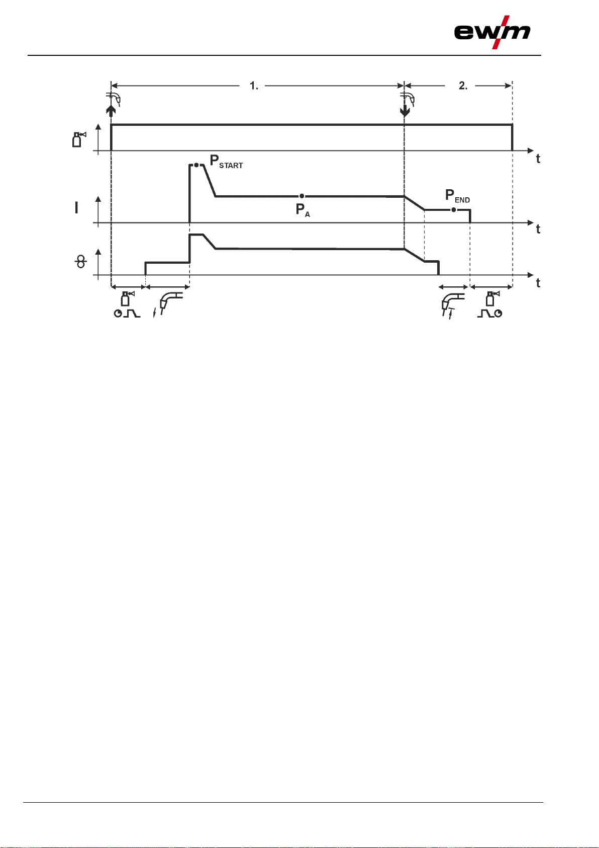
Welding procedure
MIG/MAG welding
58
099-00L105-EW501
07.06.2019
Special, non-latched
Figure 6-3
Step 1
• Press and hold torch trigger
• Shielding gas is expelled (gas pre-flows)
• Wire feed motor runs at “creep speed”.
• Arc ignites after the wire electrode makes contact with the workpiece, welding current is flowing (start
program P
for the time t
START
start
)
• Slope to main program PA.
Step 2
• Release torch trigger
• Slope to end program P
for the time t
END
end
.
• WF motor stops.
• Arc is extinguished after the preselected wire burn-back time expires.
• Gas post-flow time elapses.
Page 59
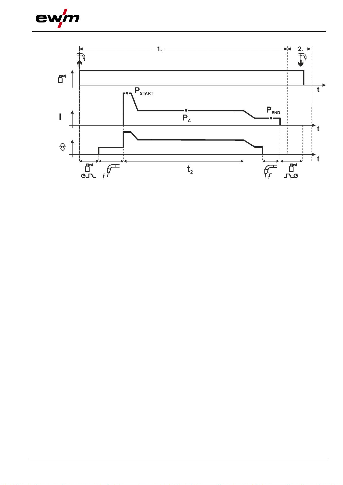
Welding procedure
MIG/MAG welding
099-00L105-EW501
07.06.2019
59
Spot welding
Figure 6-4
The ignition time t
must be added to the spot time t2.
start
1st cycle
• Press and hold torch trigger
• Shielding gas is expelled (gas pre-flows)
• Wire feed motor runs at "creep speed"
• Arc ignites after the wire electrode makes contact with the workpiece,
welding current is flowing (start program P
, spot time starts)
START
• Slope to main program PA
• After the set spot time elapses, slope goes to end program P
END
.
• Wire feed motor stop welding.
• Arc is extinguished after the pre-selected wire burn-back time elapses
• Gas post-flow time elapses.
2nd cycle
• Release torch trigger
Releasing the torch trigger (step 2) interrupts the welding process even if the spot time has not
yet elapsed (slope to end program P
END
).
Page 60
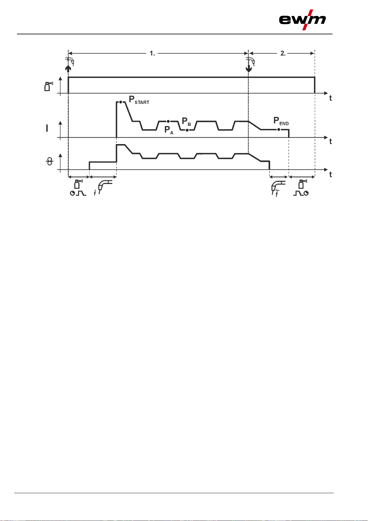
Welding procedure
MIG/MAG welding
60
099-00L105-EW501
07.06.2019
Special, non-latched with superpulse
Figure 6-5
Step 1
• Press and hold torch trigger
• Shielding gas is expelled (gas pre-flows)
• Wire feed motor runs at “creep speed”.
• Arc ignites after the wire electrode makes contact with the workpiece, welding current is flowing (start
program P
for the time t
START
start
).
• Slope on main program PA.
• Start the super pulse function beginning with main program PA:
The welding parameters change at the specified times between main program PA and the reduced
main program PB.
Step 2
• Release torch trigger
• Super pulse function is ended.
• Slope to end program P
for the time t
END
end
.
• WF motor stops.
• Arc is extinguished after the preselected wire burn-back time expires.
• Gas post-flow time elapses.
Page 61

Welding procedure
MIG/MAG welding
099-00L105-EW501
07.06.2019
61
Latched mode
Figure 6-6
Step 1
• Press and hold torch trigger
• Shielding gas is expelled (gas pre-flows)
• Wire feed motor runs at “creep speed”.
• Arc ignites after the wire electrode makes contact with the workpiece; welding current flows.
• Change over to pre-selected WF speed (main program PA).
Step 2
• Release torch trigger (no effect)
Step 3
• Press torch trigger (no effect)
Step 4
• Release torch trigger
• WF motor stops.
• Arc is extinguished after the preselected wire burn-back time expires.
• Gas post-flow time elapses.
Page 62
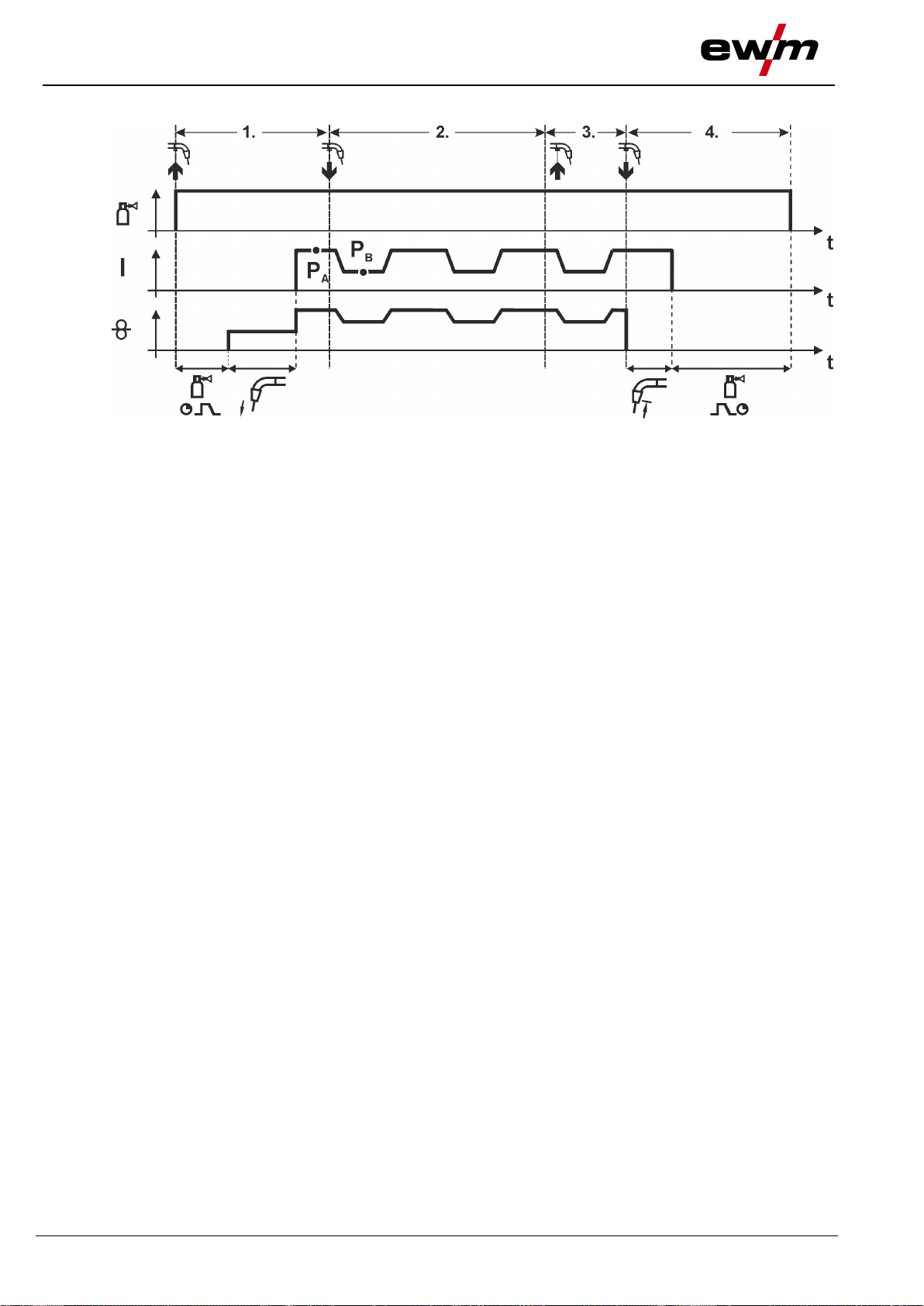
Welding procedure
MIG/MAG welding
62
099-00L105-EW501
07.06.2019
Latched mode with superpulse
Figure 6-7
Step 1:
• Press and hold torch trigger
• Shielding gas is expelled (gas pre-flows)
• Wire feed motor runs at “creep speed”.
• Arc ignites after the wire electrode makes contact with the workpiece; welding current flows.
• Start the super pulse function beginning with main program PA.
The welding parameters change at the specified times between main program PA and the reduced
main program PB.
Step 2:
• Release torch trigger (no effect)
Step 3:
• Press torch trigger (no effect)
Step 4:
• Release torch trigger
• Super pulse function is ended.
• WF motor stops.
• Arc is extinguished after the preselected wire burn-back time expires.
• Gas post-flow time elapses.
Page 63
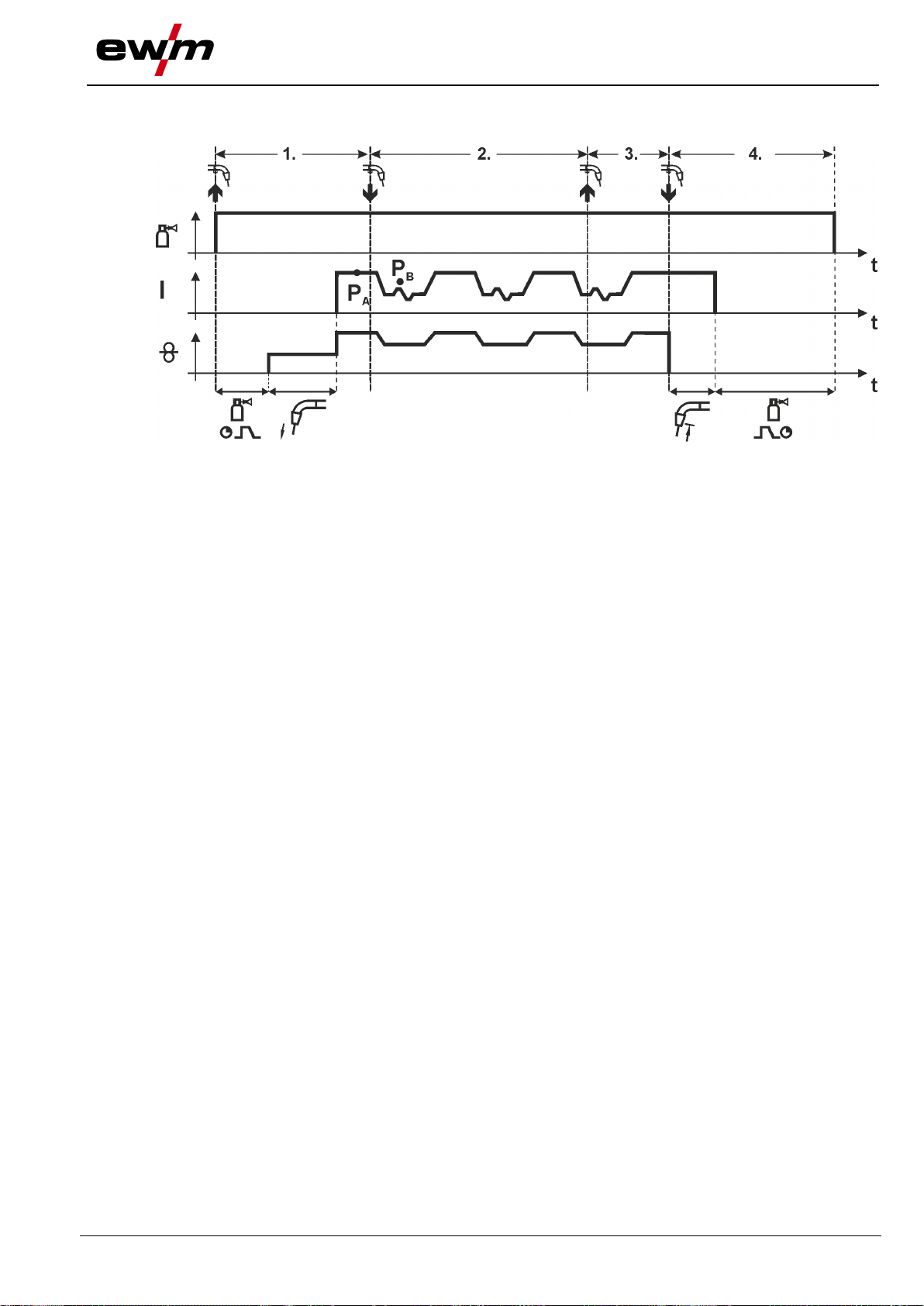
Welding procedure
MIG/MAG welding
099-00L105-EW501
07.06.2019
63
Latched with changing welding method (process switching)
Exclusively for devices with pulsed arc welding type > see 3.1 chapter.
Figure 6-8
1st cycle:
• Press and hold torch trigger
• Shielding gas is expelled (gas pre-flows)
• Wire feed motor runs at "creep speed"
• Arc ignites after the wire electrode makes contact with the workpiece; welding current flows
• Start the process alternation starting with process PA:
The welding processes alternate between the process PA stored in the JOB and the opposite process
PB at the specified times (t2 and t3)
If a standard process is stored in the JOB, this means that there is a permanent alternation
between the processes, starting with the standard process and followed by the pulse process.
The same applies if the situation is reversed.
2nd cycle:
• Release torch trigger (no effect)
3rd cycle:
• Press torch trigger (no effect)
4th cycle:
• Release torch trigger
• Super pulse function is ended
• WF motor stops
• Arc is extinguished after the pre-selected wire burn-back time elapses
• Gas post-flow time elapses
This function can be activated using the PC300.NET software.
Refer to the software operating instructions.
Page 64
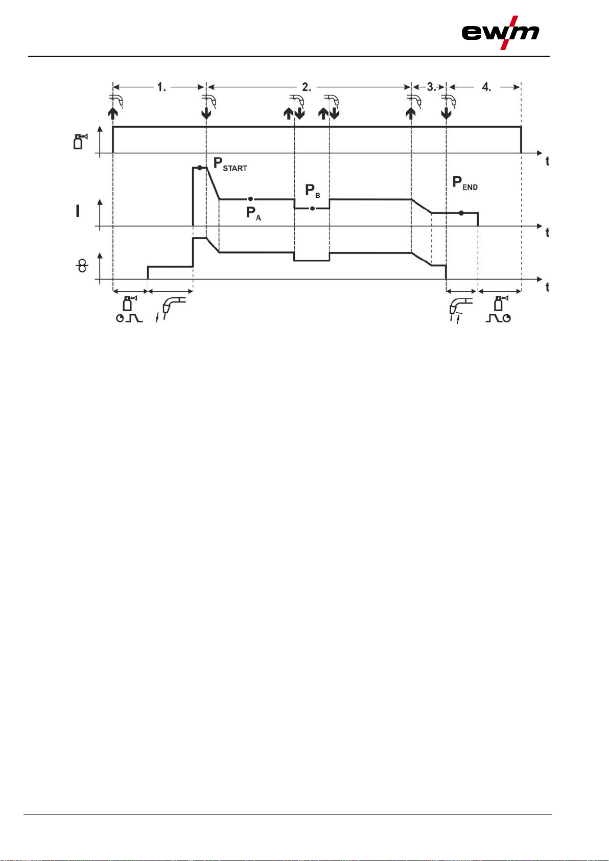
Welding procedure
MIG/MAG welding
64
099-00L105-EW501
07.06.2019
Latched special
Figure 6-9
Step 1
• Press and hold torch trigger
• Shielding gas is expelled (gas pre-flows)
• Wire feed motor runs at “creep speed”.
• Arc ignites after the wire electrode makes contact with the workpiece, welding current is flowing (start
program P
START
)
Step 2
• Release torch trigger
• Slope to main program PA.
The slope on main program PA is given at the earliest after the set time t
elapses and at the
START
latest when the torch trigger is released.
Tapping1) can be used to change over to the reduced main program PB.
Repeated tapping will switch back to the main program PA.
Step 3
• Press and hold torch trigger
• Slope to end program P
END
.
Step 4
• Release torch trigger
• WF motor stops.
• Arc is extinguished after the preselected wire burn-back time expires.
• Gas post-flow time elapses.
1)
Prevent tapping (brief press and release within 0.3 seconds)
If the welding current is to be prevented from switching over to the reduced main program PB by
tapping, the parameter value for WF3 needs to be set to 100% (PA = PB) in the program sequence.
Page 65
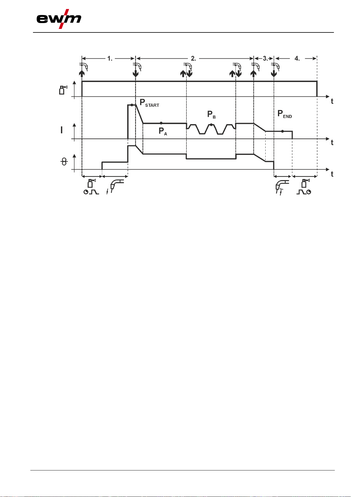
Welding procedure
MIG/MAG welding
099-00L105-EW501
07.06.2019
65
Special latched with changing welding method by tapping (process switching)
Exclusively for devices with pulsed arc welding type > see 3.1 chapter.
Figure 6-10
1st cycle
• Press and hold torch trigger.
• Shielding gas is expelled (gas pre-flows)
• Wire feed motor runs at "creep speed"
• Arc ignites after the wire electrode makes contact with the workpiece, welding current is flowing (start
program P
START
)
2nd cycle
• Release torch trigger
• Slope on main program PA
The slope on main program PA is given at the earliest after the set time t
elapses and at the
START
latest when the torch trigger is released.
Tapping (pressing the torch trigger for less than 0.3 sec.) changes over the welding process (PB).
If a standard process has been defined in the main program, tapping changes to the pulse
process, and tapping again will return to the standard process, etc.
3rd cycle
• Press and hold torch trigger
• Slope to end program P
END
4th cycle
• Release torch trigger
• WF motor stops
• Arc is extinguished after the pre-selected wire burn-back time elapses
• Gas post-flow time elapses
This function can be activated using the PC300.NET software.
Refer to the software operating instructions.
Page 66
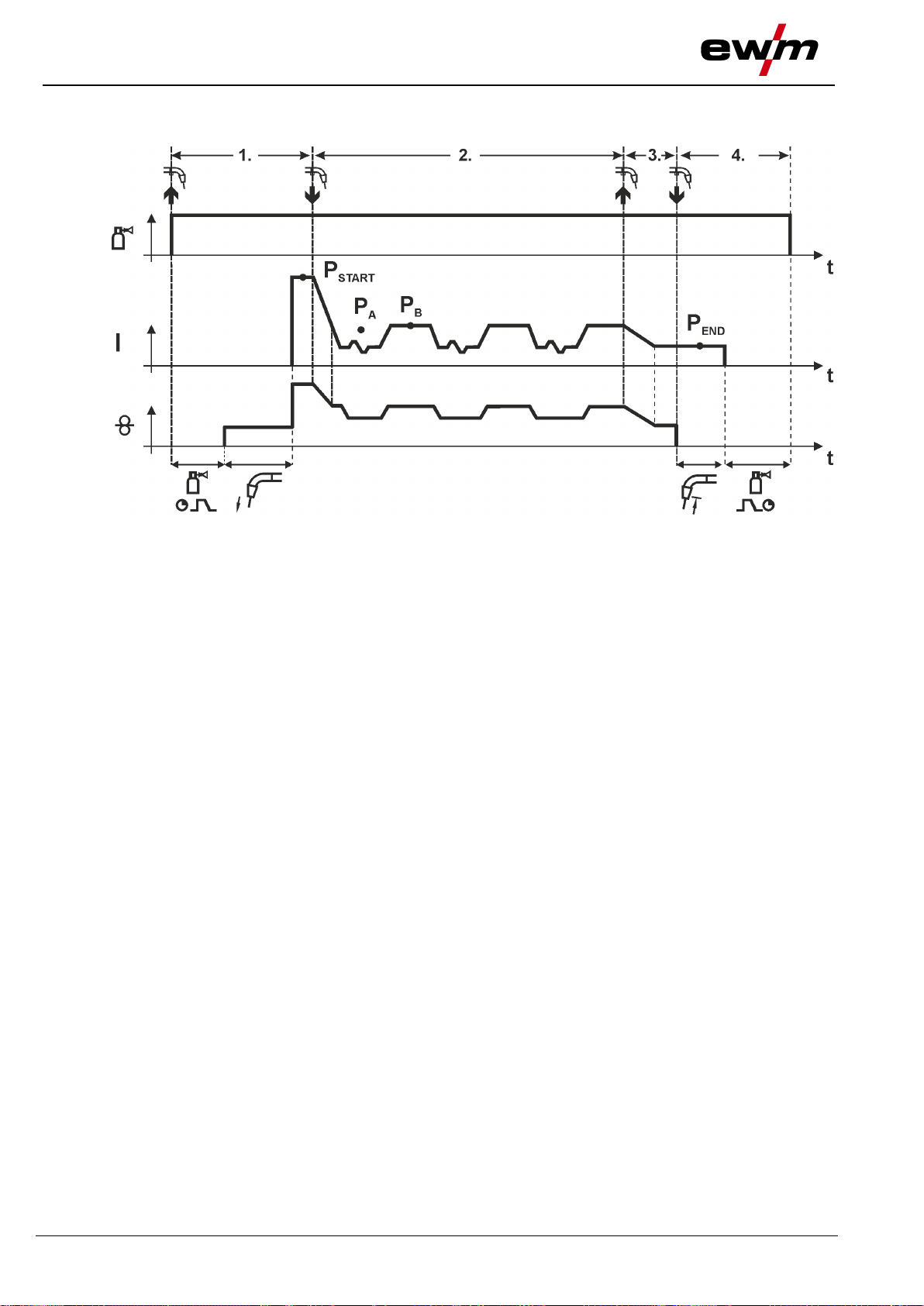
Welding procedure
MIG/MAG welding
66
099-00L105-EW501
07.06.2019
If a standard process is stored in the JOB, this means that there is a permanent alternation between the processes, starting with the standard process and followed by the pulse process. The
same applies if the situation is reversed.
Special latched with changing welding method (process switching)
Exclusively for devices with pulsed arc welding type > see 3.1 chapter.
Figure 6-11
1st cycle
• Press and hold torch trigger
• Shielding gas is expelled (gas pre-flows)
• Wire feed motor runs at "creep speed"
• Arc ignites after the wire electrode makes contact with the workpiece, welding current is flowing (start
program P
for the time t
START
start
)
2nd cycle
• Release torch trigger
• Slope on main program PA
• Start the process alternation starting with process PA:
The welding processes alternate between the process PA stored in the JOB and the opposite process
PB at the specified times (t2 and t3)
3rd cycle
• Press the torch trigger
• Super pulse function is ended
• Slope in the end program P
for the time t
END
end
4th cycle
• Release torch trigger
• WF motor stops
• Arc is extinguished after the pre-selected wire burn-back time elapses
• Gas post-flow time elapses
This function can be activated using the PC300.NET software.
Refer to the software operating instructions.
Page 67
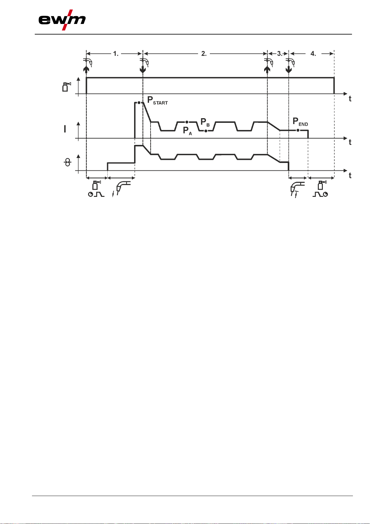
Welding procedure
MIG/MAG welding
099-00L105-EW501
07.06.2019
67
Special, latched with superpulse
Step 1
• Press and hold torch trigger
• Shielding gas is expelled (gas pre-flows)
• Wire feed motor runs at “creep speed”.
• Arc ignites after the wire electrode makes contact with the workpiece, welding current is flowing (start
program P
START
Step 2
• Release torch trigger
• Slope on main program PA.
• Start the super pulse function beginning with main program PA:
The welding parameters change at the specified times between main program PA and the reduced
main program PB.
Step 3
• Press the torch trigger.
• Super pulse function is ended.
• Slope in the end program P
Step 4
• Release torch trigger
• WF motor stops.
• Arc is extinguished after the preselected wire burn-back time expires.
• Gas post-flow time elapses.
6.1.2.2 Automatic cut-out
Once the fault periods have elapsed, the automatic cut-out stops the welding process when it has been
triggered by one of two states:
• During ignition
5 s after the start of the welding process, no welding current flows (ignition error).
• During welding
The arc is interrupted for more than 5 s (arc interruption).
for the time t
).
start
for the time t
END
Figure 6-12
.
end
Page 68

Welding procedure
MIG/MAG welding
68
099-00L105-EW501
07.06.2019
6.1.3 coldArc XQ / coldArc puls XQ
Heat-reduced, low-spatter short arc for high dimensional stability welding and brazing of thin metal sheets
with excellent gap-bridging.
After selecting the coldArc process > see 5.6 chapter you benefit from:
• Less distortion and reduced discolouration thanks to minimised heat input
• Considerably reduced spatter thanks to virtually power-free material transfer
• Easy welding of the root passes in all plate thicknesses and in all positions
• Perfect gap bridging even with inconsistent gap widths
• Manual and automated applications
You can make use of these properties after selecting the coldArc process (see the "Selecting a MIG/MAG
welding task" chapter).
With coldArc welding, it is important to ensure good quality wire feeding because of the welding filler materials being used!
• Equip the welding torch and torch hose package to suit the task! ( and the operating instructions for
the welding torch.)
This function can only be enabled with the PC300.NET software.
(See operating instructions for the software)
6.1.4 forceArc XQ / forceArc puls XQ
Heat-reduced, directionally-stable and powerful arc with deep fusion penetration for the upper power range.
Figure 6-13
Figure 6-14
• Smaller included angle due to deep penetration and directionally stable arc
• Excellent root and sidewall fusion
• Secure welding also with very long stick-outs
• Reduced undercuts
• Manual and automated applications
You can make use of these properties after selecting the forceArc process > see 5.6 chapter.
As with pulse arc welding, it is important to make sure of a good welding current connection.
• Keep welding current cables as short as possible and ensure that cable cross-sections are adequate!
• Fully unroll welding current cables, torche hose packages and, if applicable, intermediate hose packages. Avoid loops!
• Use welding torches, preferably water-cooled, that are suitable for the higher power range.
• Use welding wire with adequate copper coating when welding steel. The wire spool should have layer
spooling.
Unstable arc!
Welding current cables that are not fully unrolled can cause faults in the arc (flickering).
• Fully unroll welding current cables, torch hose packages and, if applicable, intermediate hose
packages. Avoid loops!
Page 69
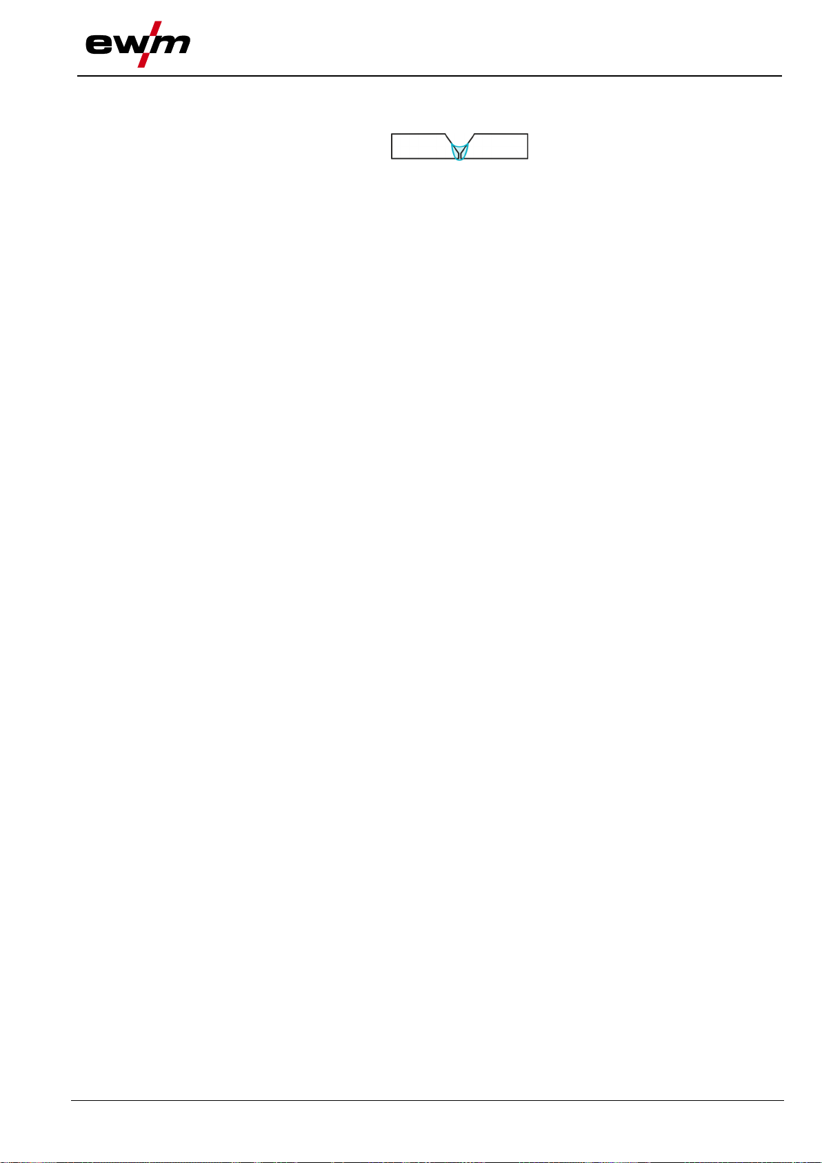
Welding procedure
MIG/MAG welding
099-00L105-EW501
07.06.2019
69
6.1.5 rootArc XQ / rootArc pulse XQ
Short arc with perfect weld modelling capabilities for effortless gap bridging, especially for root welding
• Reduced spatter compared to standard short arc
• Good root formation and secure sidewall fusion
• Manual and automated applications
Unstable arc!
Welding current cables that are not fully unrolled can cause faults in the arc (flickering).
• Fully unroll welding current cables, torch hose packages and, if applicable, intermediate hose
packages. Avoid loops!
Figure 6-15
Page 70
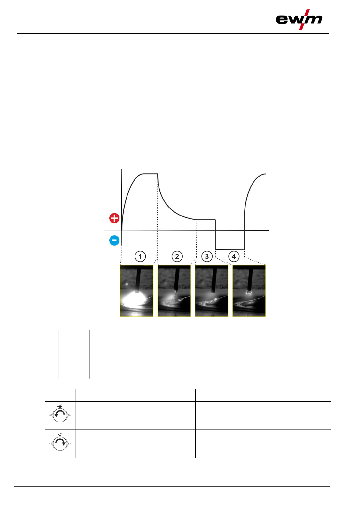
Welding procedure
MIG/MAG welding
70
099-00L105-EW501
07.06.2019
Item
Symbol
Description 0
1
Droplet formation in the pulse phase
2
Droplet detachment after the pulse phase
3
Fundamental current phase
4
Cleaning and preheating the wire in the negative phase
Setting of the dynamics
Welding properties
Left turn (more minus), negative phase
gets longer
• ---------- More power on the wire
• ---------- Droplet volume increases
• ---------- Process becomes cooler
Right turn (more plus), negative phase
gets shorter
• ---------- More power on the workpiece
• ---------- Droplet volume decreases
• ---------- Process becomes hotter
6.1.6 acArc puls XQ
The alternating current welding process acArc puls XQ makes MIG aluminium welding even easier in
manual and automated modes. Clean weld seams with no traces of powder on the thinnest metal sheets,
even with AlMg alloys, are possible with acArc puls XQ.
Advantages
• Perfect aluminium welding, especially in thin sheet metal due to directed heat reduction
• Excellent gap bridging, also facilitates automated applications
• Minimised heat input - reduces the risk of burn-through
• Less welding fume emissions
• Clean weld seams due to greatly reduced magnesium burn-off
• Easy and safe handling of the arc for manual and automated welding
A constant change of polarity (see following figure) takes place during the process.
The heat input from the material shifts to the welding consumable and the drop size increases significa-
ntly (compared to the direct current welding process). This ensures excellent bridging of air gaps and reduced welding fume emissions.
Figure 6-16
With the rotary knob “arc dynamics”, the negative phase in the process can be influenced.
Page 71
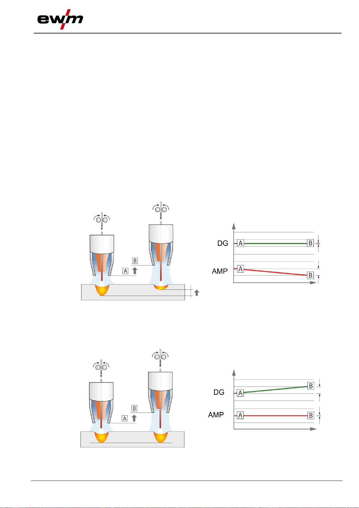
Welding procedure
MIG/MAG welding
099-00L105-EW501
07.06.2019
71
The basic requirement for optimum welding results is the application-specific equipment of the
wire feed system. For the acArc puls XQ welding process, the entire wire feed system of the
Titan XQ AC series is factory-equipped with components for aluminium welding consumables!
Recommended system components:
• Power source of type Titan XQ 400 AC puls D
• Wire feeder of type Drive XQ AC
• Welding torch series of type PM 551 W RD3 X Alu
Note the following equipment and setting features of the wire feed system:
• Wire feed rolls (set contact pressure depending on welding consumables and hose package
lengths)
• Central torch connection (use guide tube instead of capillary tube)
• Combined liner (PA liner with matching inner diameter for welding consumables)
• Use contact tips with forced contact
6.1.7 wiredArc
Welding process with active wire control for stable and uniform penetration characteristics and perfect arc
length stability, even in difficult applications and positional welding.
With a GMAW arc, the welding current (AMP) changes with the change of the stick-out. If, for instance,
the stick-out is extended, the welding current decreases at constant wire feed speed (DG). Thus, the heat
input into the workpiece (molten metal) decreases and the penetration reduces.
Figure 6-17
With the EWM wiredArc arc with wire control, the welding current (AMP) changes with the change of the
stick-out only slightly. The compensation of the welding current takes place with an active control of wire
feed speed (DG). If, for instance, the stick-out is extended, the wire feed speed will be increased. Due to
this, the welding current remains almost constant and thus the heat input into the workpiece remains almost constant. As a result, the penetration changes with the change of the stick-out only slightly.
Figure 6-18
Page 72

Welding procedure
MIG/MAG welding
72
099-00L105-EW501
07.06.2019
Operating elements
Functions
Torch trigger
• Start/stop welding
6.1.8 Standard MIG/MAG torch
The MIG welding torch trigger is essentially used to start and stop the welding process.
Additional functions such as program switching (before or after welding) are possible by tapping the torch
trigger (depending on machine type and control configuration).
The following parameters must be configured accordingly in the menu Special Parame-
ters > see 5.4.4.4 chapter .
Page 73
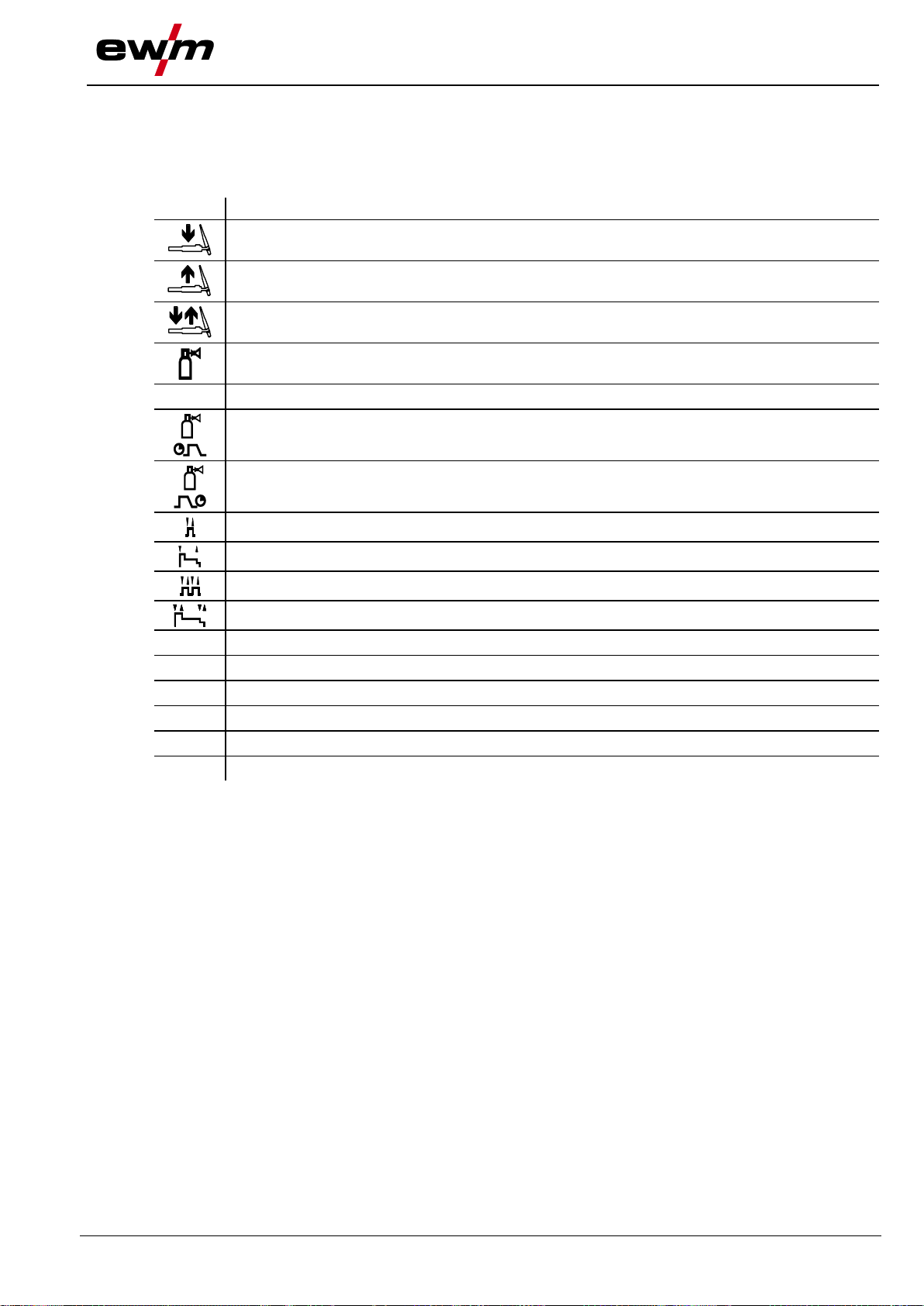
Welding procedure
TIG welding
099-00L105-EW501
07.06.2019
73
Symbol
Meaning
Press torch trigger
Release torch trigger
Tap torch trigger (press briefly and release)
Shielding gas flowing
I
Welding output
Gas pre-flows
Gas post-flows
Non-latched
Special, non-latched
Latched
Special, latched
t
Time
P
START
Ignition program
PA
Main program
PB
Reduced main program
P
END
End program
tS1
Slope duration from PSTART to PA
6.2 TIG welding
6.2.1 Operating modes (functional sequences)
6.2.1.1 Explanation of signs and functions
6.2.1.2 Automatic cut-out
Once the fault periods have elapsed, the automatic cut-out stops the welding process when it has been
triggered by one of two states:
• During ignition
5 s after the start of the welding process, no welding current flows (ignition error).
• During welding
The arc is interrupted for more than 5 s (arc interruption).
Page 74

Welding procedure
TIG welding
74
099-00L105-EW501
07.06.2019
Non-latched mode
Figure 6-19
Selection
• Select non-latched operating mode .
Step 1
• Press and hold torch trigger.
• Shielding gas is expelled (gas pre-flows).
The arc is ignited using liftarc.
• Welding current flows with pre-selected setting.
Step 2
• Release torch trigger.
• Arc is extinguished.
• Gas post-flow time elapses.
Special, non-latched
Figure 6-20
Selection
• Select non-latched special mode .
Step 1
• Press and hold torch trigger
• Shielding gas is expelled (gas pre-flows)
The arc is ignited using liftarc.
• Welding gas flows with pre-selected setting in start program “P
START
”.
• After the “tstart” ignition current time elapses, the welding current rises with the set upslope time “tS1”
to the main program “PA”.
Step 2
• Release torch trigger.
• The welding current reduces with the downslope time “tSe” to the end program “P
END
”.
• After the end current time “end” elapses, the arc will extinguish.
• Gas post-flow time elapses.
Page 75
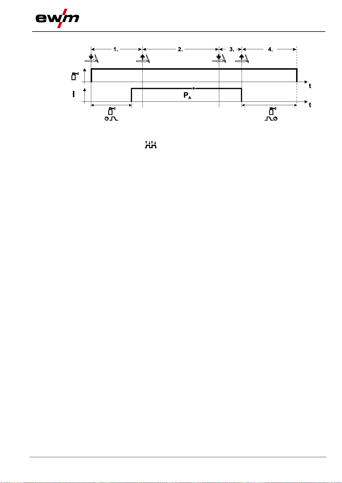
Welding procedure
TIG welding
099-00L105-EW501
07.06.2019
75
Latched mode
Figure 6-21
Selection
• Select latched operating mode .
Step 1
• Press and hold torch trigger
• Shielding gas is expelled (gas pre-flows)
The arc is ignited using liftarc.
• Welding current flows with pre-selected setting.
Step 2
• Release torch trigger (no effect)
Step 3
• Press torch trigger (no effect)
Step 4
• Release torch trigger
• Arc is extinguished.
• Gas post-flow time elapses.
Page 76

Welding procedure
TIG welding
76
099-00L105-EW501
07.06.2019
Latched special
Figure 6-22
Selection
• Select latched special mode .
Step 1
• Press and hold torch trigger.
• Shielding gas is expelled (gas pre-flows).
The arc is ignited using liftarc.
• Welding gas flows at pre-selected setting in start program "P
START
".
Step 2
• Release torch trigger.
• Slope on main program "PA".
The slope on main program PA is given at the earliest after the set time t
elapses and at the
START
latest when the torch trigger is released.
Tapping can be used to switch to the reduced main program "PB". Repeated tapping will switch
back to the main program "PA".
Step 3
• Press the torch trigger.
• Slope to end program "P
END
".
Step 4
• Release torch trigger.
• Arc is extinguished.
• Gas post-flow time elapses.
Page 77
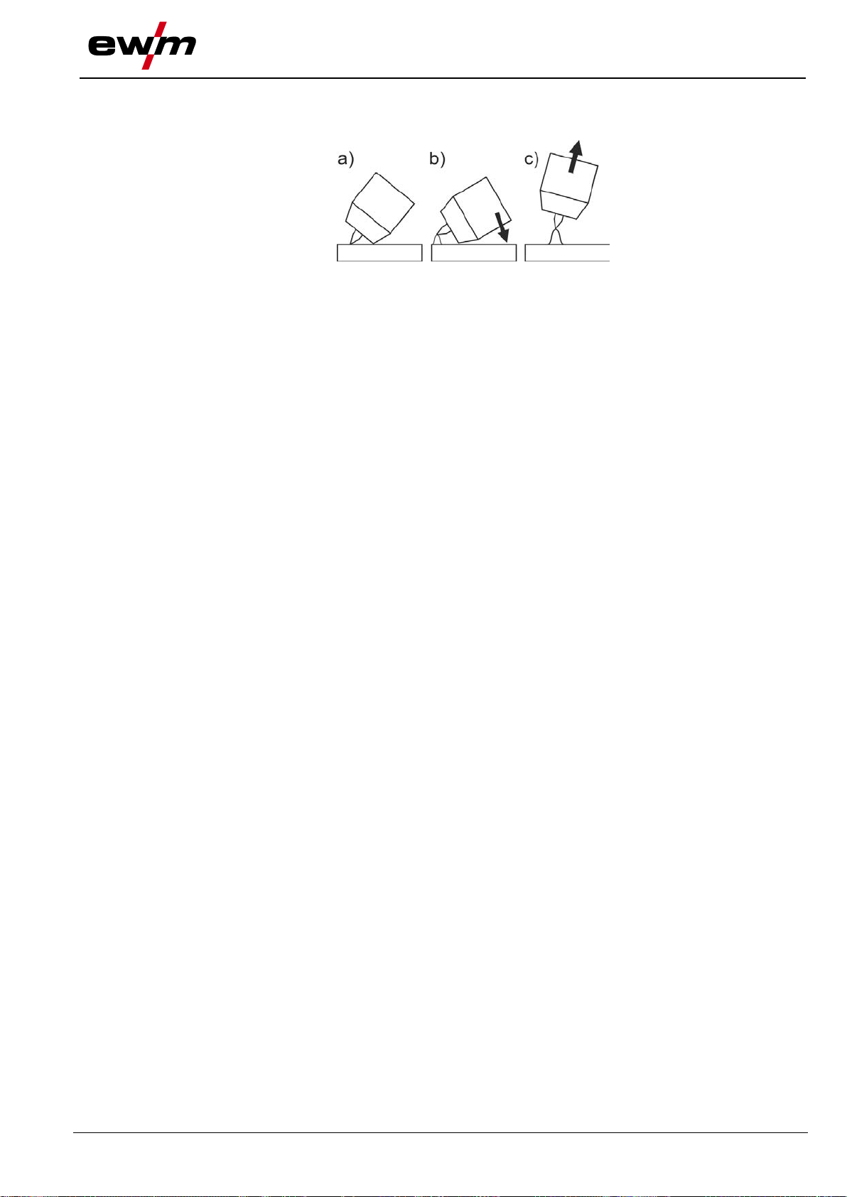
Welding procedure
TIG welding
099-00L105-EW501
07.06.2019
77
6.2.2 Arc ignition
6.2.2.1 Liftarc
The arc ignites through contact with the workpiece:
a) Carefully place the torch gas nozzle and tungsten electrode tip against the workpiece (lift arc current
flows independent of the set main current)
b) Angle the torch above the torch gas nozzle until the distance between electrode tip and workpiece is
approx. 2–3 mm (arc ignites, current increases to the set main current).
c) Lift the torch off and bring into normal position.
Complete the welding task: Remove the torch from the workpiece so that the arc extinguishes.
Figure 6-23
Page 78

Welding procedure
MMA welding
78
099-00L105-EW501
07.06.2019
A = Hot start current
B = Hot start time
C = Main current
I = Current
t = Time
The Antistick feature prevents the electrode from annealing.
Should the electrode stick despite the Arcforce feature, the machine
automatically switches to the minimum current within approx. one second. This prevents the electrode from annealing. Check the welding
current setting and correct for the welding task in hand.
6.3 MMA welding
6.3.1 Hotstart
The function hot start ensures a secure igniting of the arc and a sufficient heating to the still cold parent
metal at the beginning of the welding process. The ignition takes place here with increased current (hot
start current) over a certain time (hot start time).
6.3.2 Antistick
6.4 Air arc gouging
During gouging, an arc burns between a carbon electrode and the workpiece, heating the workpiece until
it is molten. At the same time, the molten metal is blown out with compressed air. Special electrode holders with a compressed-air connection and carbon electrodes are required for gouging.
Figure 6-24
Figure 6-25
Page 79

Rectifying faults
Display machine control software version
099-00L105-EW501
07.06.2019
79
7 Rectifying faults
All products are subject to rigorous production checks and final checks. If, despite this, something fails to
work at any time, please check the product using the following flowchart. If none of the fault rectification
procedures described leads to the correct functioning of the product, please inform your authorised dea-
7.1 Display machine control software version
ler.
Identifying the machine software is key to quick troubleshooting by the authorised service technician. The
version number is shown on the initial screen of the machine control for about 5 seconds (switch the ma-
chine off and on again) > see 4.3.3 chapter.
Page 80

Rectifying faults
Warnings
80
099-00L105-EW501
07.06.2019
Display type - machine control
Display
Graphic display
two 7-segment displays
one 7-segment display
No.
Warning
Possible cause
1
Excess temperature
A shutdown is imminent due to excess temperature.
4
Shielding gas
[2]
Check shielding gas supply.
5
Coolant flow
[3]
Flow rate (<= 0.7l/min / <= 0.18 gal./min)
[1]
6
low wire
Only a small amount of wire is left on the spool.
7
CAN bus failure
Wire feeder not connected, automatic circuit-breaker of wire
feed motor (reset the tripped automatic circuit-breaker by actuating).
8
Welding circuit
The welding circuit inductance is too high for the selected
welding task.
10
Partial inverter
One of several partial inverters is not supplying welding current.
11
Excess temperature, coolant
[3]
Coolant (>= 65°C / >= 149°F)
[1]
12
Welding monitor
The actual value of a welding parameter is outside the specified tolerance field.
13
Contact error
The resistance in the welding circuit is too high. Check earth
connection.
32
Tacho error
Fault of wire feeder, permanent overload of the wire drive.
33
WF excess current
Overcurrent detection of the main WF drive.
34
JOB unknown
JOB selection was not performed because the JOB number is
unknown.
35
WF excess current slave
Overload of the slave WF drive (front drive push/push system
or intermediate drive).
36
Slave tacho error
Fault of wire feeder, permanent overload of the slave WF drive
(front drive push/push system or intermediate drive).
37
FST bus failure
Wire feeder not connected, automatic circuit-breaker of wire
feed motor (reset the tripped automatic circuit-breaker by actuating).
7.2 Warnings
Depending on the display options of the machine display, a warning message is displayed as follows:
The cause of the warning is indicated by a corresponding warning number (see table).
• In case of multiple warnings, these are displayed in sequence.
• Document machine warning and inform service personnel, if required.
[1]
factory setting
[2]
option
[3]
only machine series Titan XQ
Page 81
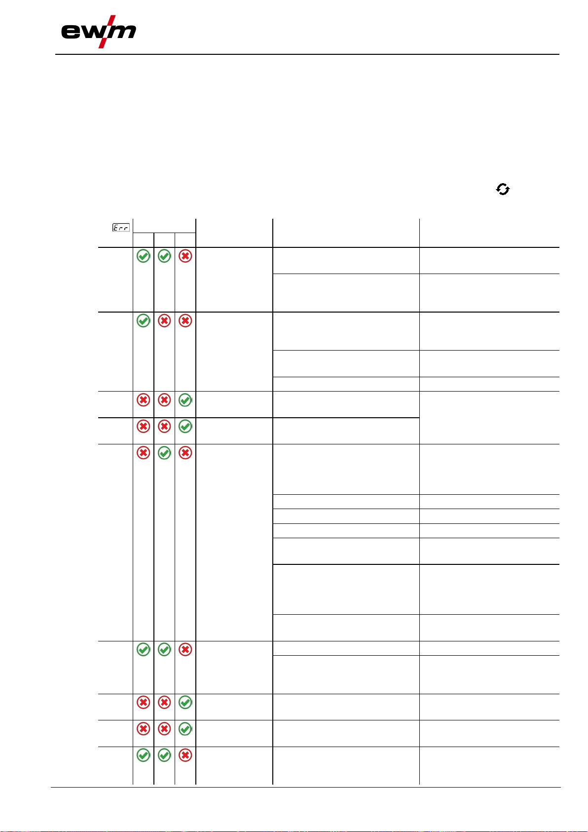
Rectifying faults
Error messages
099-00L105-EW501
07.06.2019
81
Category
Error
Possible cause
Remedy
a)
b)
c)
3
Tacho error
Error of wire feeder
Check connections (connections, pipes)
Permanent overload of the wire
drive
Do not place the liner in tight
radii; check wire core for
smooth movement
4
Excess temperature
Power source overheated
Allow the power source to
cool down (mains switch to
“1”)
Fan blocked, dirty or defective
Check fan and clean or replace
Air inlet or outlet blocked
Check air inlet and outlet
5
Mains overvoltage
Mains voltage is too high
Check the mains voltages and
compare with the power
source connection voltages
6
Mains undervoltage
Mains voltage is too low
7
Low coolant
level
Flow rate too low (< = 0.7 l/min)
/ (< = 0.18 gal/min)
[1] [3]
Check coolant flow, clean
water block, remove kinks in
hose package, adjust flow
threshold
Coolant volume too low
Fill coolant
Pump does not run
Turn the pump shaft
Air in the coolant circuit
Vent coolant circuit
Hose package not completely
filled with coolant
Switch machine off / on (pump
runs for 2 min)
Operation with gas-cooled
welding torch
Connect coolant feed and
coolant return (insert hose
bridge); deactivate water
block
Failure of automatic circuitbreaker
[4]
Press to reset automatic circuit-breaker
8
Shielding gas
error
[2]
No shielding gas
Check shielding gas supply
Pre-pressure too low
Remove kinks in the hose
package; nominal value:
4-6 bar primary pressure
9
Sec. overvoltage
Overvoltage at output: Inverter
error
Inform Service
10
Earth fault (PE
error)
Connection between welding
wire and machine casing
Remove electrical connection
11
Quick shutdown
Removing the logical signal
“robot ready” during the process
Eliminate errors on the higherlevel control
7.3 Error messages
A welding machine error will be signalled by an error code (see table) on the control display. In
the event of an error, the power unit shuts down.
The display of possible error numbers depends on the machine version (interfaces/functions).
• Document machine errors and inform service staff as necessary.
• If multiple errors occur, these are displayed in succession.
Legend for categories (reset error)
a) The error message will disappear once the error has been rectified.
b) The error message can be reset by pressing a context-dependent push-button with the icon.
c) The error message can only be reset by switching the machine off and on again.
Page 82
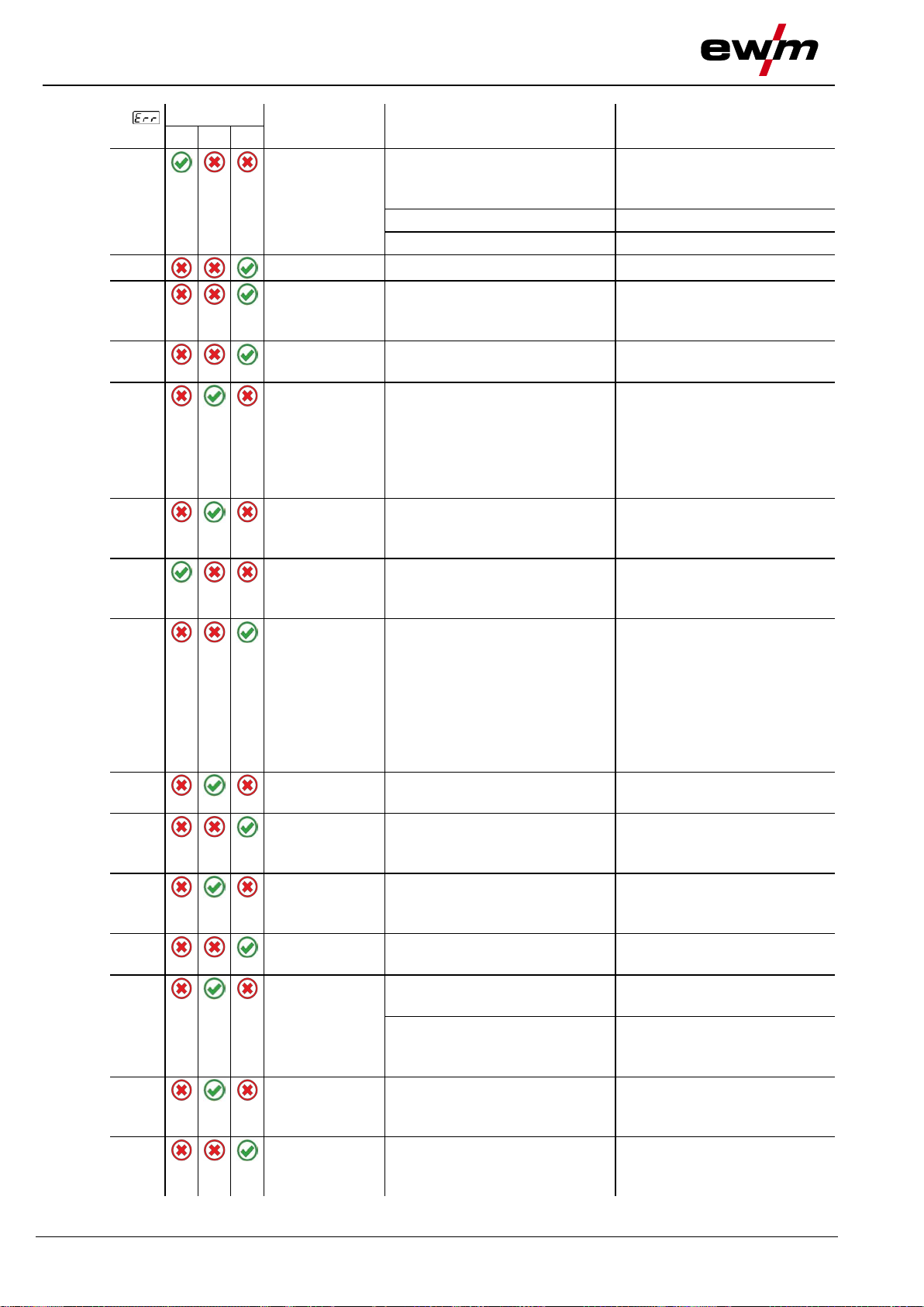
Rectifying faults
Error messages
82
099-00L105-EW501
07.06.2019
Category
Error
Possible cause
Remedy
a)
b)
c)
22
Coolant excess
temperature
[3]
Coolant is overheating (>=70°C
/ >=158°F)
[1]
measured in the
coolant return line
Allow the power source to
cool down (mains switch to
“1”)
Fan blocked, dirty or defective
Check fan, clean or replace
Air inlet or outlet blocked
Check air inlet and outlet
32
Error I>0
[3]
Inform Service
33
Error UIST
[3]
Short circuit in welding circuit
before welding
Eliminate short circuit in
welding circuit; remove external sensor voltage
38
Error IIST
[3]
Short circuit in welding circuit
before welding
Eliminate short circuit in
welding circuit
48
Ignition error
No ignition occurred during a
process start with automated
machines
Check the wire feeding, check
the connections of the load
cables in the welding circuit,
clean corroded surfaces on
the workpiece before welding
if applicable
49
Arc interruption
An arc interruption occurred
during welding with an automated system
Check wire feeding; adjust
welding speed.
51
Emergency
stop
The emergency stop circuit of
the power source has been
activated.
Disable the activation of the
emergency stop circuit (release protective circuit)
52
No wire feeder
After switching on the automated system, no wire feeder was
detected
Check or connect control
cables of wire feeders; check
the identification number of
the automated wire feeder (for
1DV: number 1, for 2DV: each
a wire feeder with number 1
and a wire feeder with number
2)
53
No wire feeder
2
Wire feeder 2 not detected
Check or connect the control
lines of the wire feeders
54
VRD error
[2]
Open circuit voltage reduction
error
if necessary, disconnect external machine from the
welding circuit; inform Service
55
WF excess
current
Overcurrent detection on wire
feeder
Do not place the liner in tight
radii; check wire core for
smooth movement
56
Mains phase
failure
One phase of the mains voltage
has failed
Check mains connection,
mains plug and mains fuses
57
Slave tacho
error
Wire feeder fault (slave drive)
Check connectors, cables,
connections
Permanent overload of the wire
drive (slave drive)
Do not place the liner in tight
radii; check wire core for
smooth movement
58
Short circuit
Check welding circuit for short
circuit
Check welding circuit; isolate
welding torch before depositing
59
Incompatible
machine
A machine connected to the
system is not compatible
Please disconnect the incompatible machine from the system
Page 83
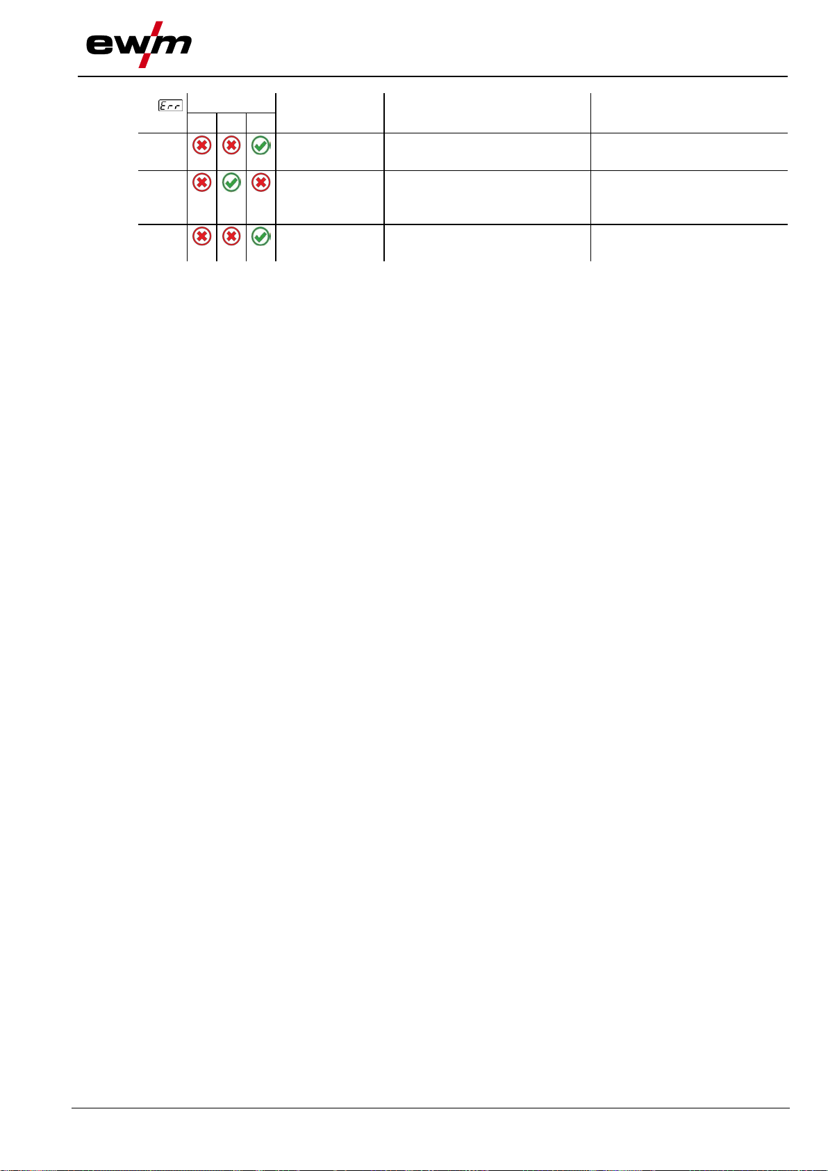
Rectifying faults
Resetting JOBs (welding tasks) to the factory settings
099-00L105-EW501
07.06.2019
83
Category
Error
Possible cause
Remedy
a)
b)
c)
60
Incompatible
software
A machine's software is not
compatible.
Inform Service
61
Welding monitor
The actual value of a welding
parameter is outside the specified tolerance field
Observe tolerance fields; adjust welding parameters
62
System component
[3]
System component not found
Inform Service
[1]
factory setting
[2]
option
[3]
only machine series Titan
[4]
not machine series Titan
7.4 Resetting JOBs (welding tasks) to the factory settings
All customised welding parameters that are stored will be replaced by the factory settings.
Instructions on how to reset welding tasks (JOBs) to the factory setting can be found in the JOB mana-
ger > see 5.6.3 chapter chapter.
Page 84
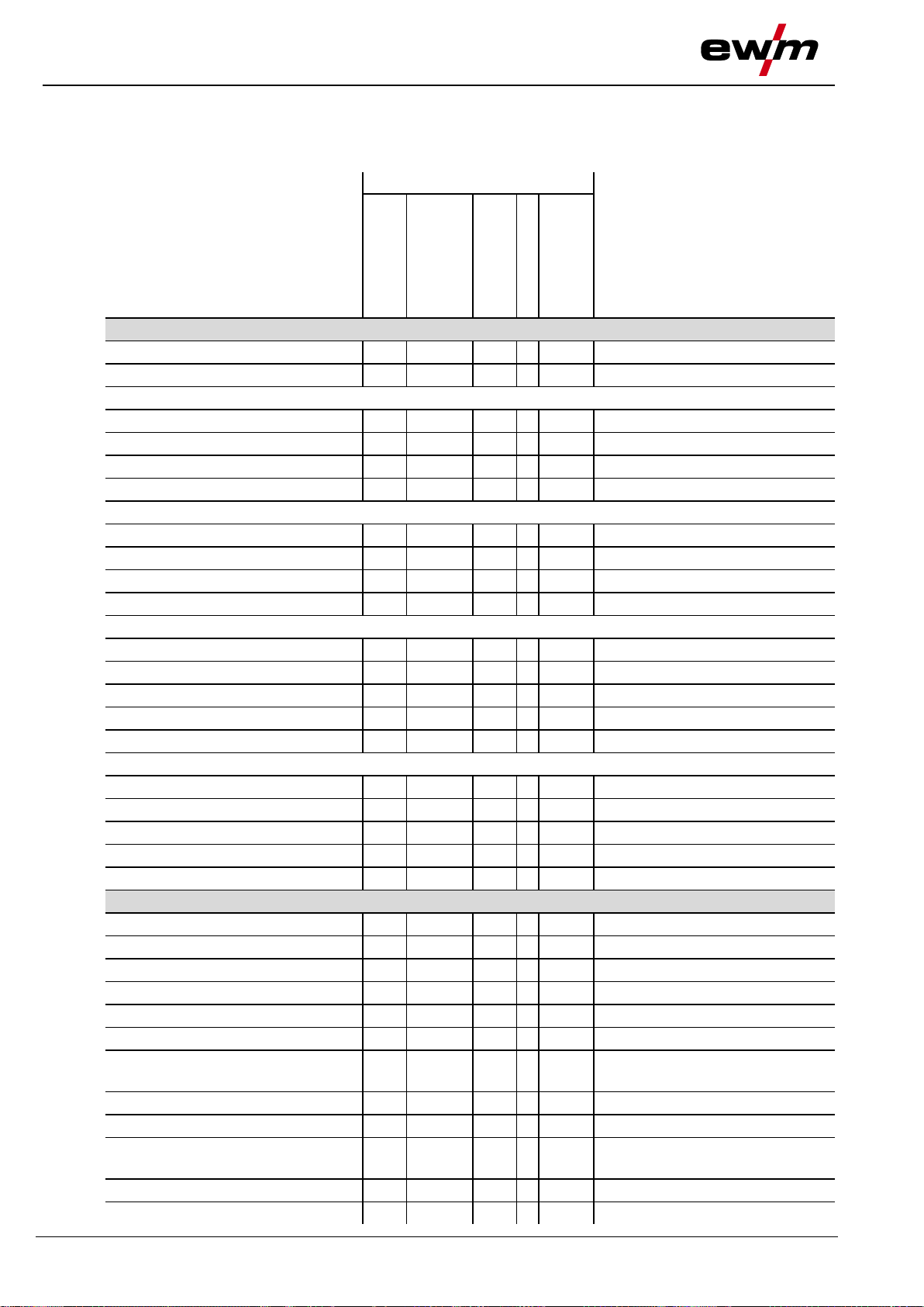
Appendix
Parameter overview – setting ranges
84
099-00L105-EW501
07.06.2019
Parameter
Setting range
Comment
Standard
Unit
Min. Max.
MIG/MAG
Gas pre-flow time
0,1 s 0 - 20
Gas nominal value
l/min.
GFE option
Start program P
START
WF relative
55 % 1 - 200
Duration
0,1 s 0,00 - 20,0
U correction
0 V -9,9 - 9,9
Slope time
0,6 s 0,00 20,0
Main program PA
WF [/min.]
0,01
m/min.
0,00 - 20,0
U correction
0 V -9,9 - 9,9
Duration
0,15
s
0,00 - 20,0
Slope time
0,10
s
0,00 - 20,0
Down-slope program PB
WF relative
60 % 0 - 200
Duration
0,40 s 0,0 - 20,0
U correction
0 V -9,9 - 9,9
Slope time
0,05
s
0,00 - 20,0
Slope time
0,00
s
0,00 - 20,0
End program P
END
WF relative
100 % 0 - 200
Duration
0,00 s 0,0 - 20,0
U correction
0 V -9,9 - 9,9
Wire burn-back
15 0 499
Gas post-flow time
0,5 s 0,0 20,0
TIG
Gas pre-flow time
0,1 s 0 - 20
Ignition current AMP%
50 % 0 - 200
% of main current AMP
Start time
0,5 s 0,00 - 20,0
Up-slope time
0,5 s 0,0 - 20,0
Pulse current
140 % 1 200
Pulse time
0,2 s 0,01 - 20,0
Slope time
0,1 s 0,00 - 20,0
Time from main current AMP to
secondary current AMP%
Secondary current AMP%
50 % 1 200
% of main current AMP
Pulse pause time
0,2 s 0,01 - 20,0
Slope time
0,1 s 0,00 - 20,0
Time from main current AMP to
secondary current AMP%
Down-slope time
0,5 s 0,0 - 20,0
End current AMP%
30 % 0 - 200
% of main current AMP
8 Appendix
8.1 Parameter overview – setting ranges
Page 85
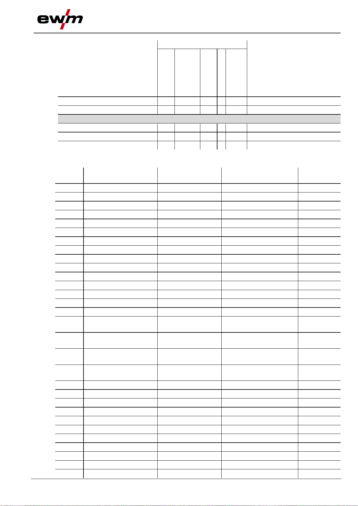
Appendix
JOB-List
099-00L105-EW501
07.06.2019
85
Parameter
Setting range
Comment
Standard
Unit
Min. Max.
End current time
0,5 s 0,00 - 20,0
Gas post-flow time
5 s 0,0 - 20,0
MMA
Hot start current
120 % 1 - 200
Hot start time
0,5 s 0,0 - -10,0
Arcforce
0 -40 - 40
JOB no.
Processes
Material
Gas
Diameter
[mm]
1
GMAW standard
G3Si1 / G4Si1
100% CO2
0,8
2
GMAW standard
G3Si1 / G4Si1
100% CO2
0,9
3
GMAW standard
G3Si1 / G4Si1
100% CO2
1,0
4
GMAW standard
G3Si1 / G4Si1
100% CO2
1,2
5
GMAW standard
G3Si1 / G4Si1
100% CO2
1,6
6
Standard GMAW / pulse
G3Si1 / G4Si1
Ar-82 / CO2-18 (M21)
0,8
7
Standard GMAW / pulse
G3Si1 / G4Si1
Ar-82 / CO2-18 (M21)
0,9
8
Standard GMAW / pulse
G3Si1 / G4Si1
Ar-82 / CO2-18 (M21)
1,0
9
Standard GMAW / pulse
G3Si1 / G4Si1
Ar-82 / CO2-18 (M21)
1,2
10
Standard GMAW / pulse
G3Si1 / G4Si1
Ar-82 / CO2-18 (M21)
1,6
11
Standard GMAW / pulse
G3Si1 / G4Si1
Ar-90 / CO2-10 (M20)
0,8
12
Standard GMAW / pulse
G3Si1 / G4Si1
Ar-90 / CO2-10 (M20)
0,9
13
Standard GMAW / pulse
G3Si1 / G4Si1
Ar-90 / CO2-10 (M20)
1,0
14
Standard GMAW / pulse
G3Si1 / G4Si1
Ar-90 / CO2-10 (M20)
1,2
15
Standard GMAW / pulse
G3Si1 / G4Si1
Ar-90 / CO2-10 (M20)
1,6
26
Standard GMAW / pulse
CrNi 19 12 3 Nb /
1.4576
Ar-97.5 / CO2-2.5 (M12)
0,8
27
Standard GMAW / pulse
CrNi 19 12 3 Nb /
1.4576
Ar-97.5 / CO2-2.5 (M12)
1,0
28
Standard GMAW / pulse
CrNi 19 12 3 Nb /
1.4576
Ar-97.5 / CO2-2.5 (M12)
1,2
29
Standard GMAW / pulse
CrNi 19 12 3 Nb /
1.4576
Ar-97.5 / CO2-2.5 (M12)
1,6
30
Standard GMAW / pulse
CrNi 18 8 / 1.4370
Ar-97.5 / CO2-2.5 (M12)
0,8
31
Standard GMAW / pulse
CrNi 18 8 / 1.4370
Ar-97.5 / CO2-2.5 (M12)
1,0
32
Standard GMAW / pulse
CrNi 18 8 / 1.4370
Ar-97.5 / CO2-2.5 (M12)
1,2
33
Standard GMAW / pulse
CrNi 18 8 / 1.4370
Ar-97.5 / CO2-2.5 (M12)
1,6
34
Standard GMAW / pulse
CrNi 19 9 / 1.4316
Ar-97.5 / CO2-2.5 (M12)
0,8
35
Standard GMAW / pulse
CrNi 19 9 / 1.4316
Ar-97.5 / CO2-2.5 (M12)
1,0
36
Standard GMAW / pulse
CrNi 19 9 / 1.4316
Ar-97.5 / CO2-2.5 (M12)
1,2
37
Standard GMAW / pulse
CrNi 19 9 / 1.4316
Ar-97.5 / CO2-2.5 (M12)
1,6
38
Standard GMAW / pulse
CrNi 19 12 3 / 1.4430
Ar-97.5 / CO2-2.5 (M12)
0,8
39
Standard GMAW / pulse
CrNi 19 12 3 / 1.4430
Ar-97.5 / CO2-2.5 (M12)
1,0
40
Standard GMAW / pulse
CrNi 19 12 3 / 1.4430
Ar-97.5 / CO2-2.5 (M12)
1,2
8.2 JOB-List
Page 86

Appendix
JOB-List
86
099-00L105-EW501
07.06.2019
JOB no.
Processes
Material
Gas
Diameter
[mm]
41
Standard GMAW / pulse
CrNi 19 12 3 / 1.4430
Ar-97.5 / CO2-2.5 (M12)
1,6
42
Standard GMAW / pulse
CrNi 22 9 3 / 1.4462
Ar-97.5 / CO2-2.5 (M12)
0,8
43
Standard GMAW / pulse
CrNi 22 9 3 / 1.4462
Ar-97.5 / CO2-2.5 (M12)
1,0
44
Standard GMAW / pulse
CrNi 22 9 3 / 1.4462
Ar-97.5 / CO2-2.5 (M12)
1,2
45
Standard GMAW / pulse
CrNi 22 9 3 / 1.4462
Ar-97.5 / CO2-2.5 (M12)
1,6
46
Standard GMAW / pulse
CrNi 22 9 3 / 1.4462
Ar-78 / He-20 / CO2-2
(M12)
0,8
47
Standard GMAW / pulse
CrNi 22 9 3 / 1.4462
Ar-78 / He-20 / CO2-2
(M12)
1,0
48
Standard GMAW / pulse
CrNi 22 9 3 / 1.4462
Ar-78 / He-20 / CO2-2
(M12)
1,2
49
Standard GMAW / pulse
CrNi 22 9 3 / 1.4462
Ar-78 / He-20 / CO2-2
(M12)
1,6
50
coldArc / coldArc puls
CrNi 19 9 / 1.4316
Ar-97.5 / CO2-2.5 (M12)
0,8
51
coldArc / coldArc puls
CrNi 19 9 / 1.4316
Ar-97.5 / CO2-2.5 (M12)
1,0
52
coldArc / coldArc puls
CrNi 19 9 / 1.4316
Ar-97.5 / CO2-2.5 (M12)
1,2
55
coldArc / coldArc puls
AlMg4.5Mn
Ar-100 (I1)
1,0
56
coldArc / coldArc puls
AlMg4.5Mn
Ar-100 (I1)
1,2
59
coldArc / coldArc puls
AlSi
Ar-100 (I1)
1,0
60
coldArc / coldArc puls
AlSi
Ar-100 (I1)
1,2
63
coldArc / coldArc puls
Al99
Ar-100 (I1)
1,0
64
coldArc / coldArc puls
Al99
Ar-100 (I1)
1,2
66
coldArc Brazing
CuSi
Ar-100 (I1)
0,8
67
coldArc Brazing
CuSi
Ar-100 (I1)
1,0
68
coldArc Brazing
CuSi
Ar-100 (I1)
1,2
70
coldArc Brazing
CuAl
Ar-100 (I1)
0,8
71
coldArc Brazing
CuAl
Ar-100 (I1)
1,0
72
coldArc Brazing
CuAl
Ar-100 (I1)
1,2
74
Standard GMAW / pulse
AlMg4.5Mn
Ar-100 (I1)
0,8
75
Standard GMAW / pulse
AlMg4.5Mn
Ar-100 (I1)
1,0
76
Standard GMAW / pulse
AlMg4.5Mn
Ar-100 (I1)
1,2
77
Standard GMAW / pulse
AlMg4.5Mn
Ar-100 (I1)
1,6
78
Standard GMAW / pulse
AlMg4.5Mn
Ar-70 / He-30 (I3)
0,8
79
Standard GMAW / pulse
AlMg4.5Mn
Ar-70 / He-30 (I3)
1,0
80
Standard GMAW / pulse
AlMg4.5Mn
Ar-70 / He-30 (I3)
1,2
81
Standard GMAW / pulse
AlMg4.5Mn
Ar-70 / He-30 (I3)
1,6
82
Standard GMAW / pulse
AlSi
Ar-100 (I1)
0,8
83
Standard GMAW / pulse
AlSi
Ar-100 (I1)
1,0
84
Standard GMAW / pulse
AlSi
Ar-100 (I1)
1,2
85
Standard GMAW / pulse
AlSi
Ar-100 (I1)
1,6
86
Standard GMAW / pulse
AlSi
Ar-70 / He-30 (I3)
0,8
87
Standard GMAW / pulse
AlSi
Ar-70 / He-30 (I3)
1,0
88
Standard GMAW / pulse
AlSi
Ar-70 / He-30 (I3)
1,2
89
Standard GMAW / pulse
AlSi
Ar-70 / He-30 (I3)
1,6
90
Standard GMAW / pulse
Al99
Ar-100 (I1)
0,8
91
Standard GMAW / pulse
Al99
Ar-100 (I1)
1,0
92
Standard GMAW / pulse
Al99
Ar-100 (I1)
1,2
93
Standard GMAW / pulse
Al99
Ar-100 (I1)
1,6
Page 87
Appendix
JOB-List
099-00L105-EW501
07.06.2019
87
JOB no.
Processes
Material
Gas
Diameter
[mm]
94
Standard GMAW / pulse
Al99
Ar-70 / He-30 (I3)
0,8
95
Standard GMAW / pulse
Al99
Ar-70 / He-30 (I3)
1,0
96
Standard GMAW / pulse
Al99
Ar-70 / He-30 (I3)
1,2
97
Standard GMAW / pulse
Al99
Ar-70 / He-30 (I3)
1,6
98
Standard GMAW / pulse
CuSi
Ar-100 (I1)
0,8
99
Standard GMAW / pulse
CuSi
Ar-100 (I1)
1,0
100
Standard GMAW / pulse
CuSi
Ar-100 (I1)
1,2
101
Standard GMAW / pulse
CuSi
Ar-100 (I1)
1,6
102
Standard GMAW / pulse
CuSi
Ar-97.5 / CO2-2.5 (M12)
0,8
103
Standard GMAW / pulse
CuSi
Ar-97.5 / CO2-2.5 (M12)
1,0
104
Standard GMAW / pulse
CuSi
Ar-97.5 / CO2-2.5 (M12)
1,2
105
Standard GMAW / pulse
CuSi
Ar-97.5 / CO2-2.5 (M12)
1,6
106
Standard GMAW / pulse
CuAl
Ar-100 (I1)
0,8
107
Standard GMAW / pulse
CuAl
Ar-100 (I1)
1,0
108
Standard GMAW / pulse
CuAl
Ar-100 (I1)
1,2
109
Standard GMAW / pulse
CuAl
Ar-100 (I1)
1,6
110
Brazing
CuSi
Ar-97.5 / CO2-2.5 (M12)
0,8
111
Brazing
CuSi
Ar-97.5 / CO2-2.5 (M12)
1,0
112
Brazing
CuSi
Ar-97.5 / CO2-2.5 (M12)
1,2
113
Brazing
CuSi
Ar-97.5 / CO2-2.5 (M12)
1,6
114
Brazing
CuSi
Ar-100 (I1)
0,8
115
Brazing
CuSi
Ar-100 (I1)
1,0
116
Brazing
CuSi
Ar-100 (I1)
1,2
117
Brazing
CuSi
Ar-100 (I1)
1,6
118
Brazing
CuAl
Ar-97.5 / CO2-2.5 (M12)
0,8
119
Brazing
CuAl
Ar-97.5 / CO2-2.5 (M12)
1,0
120
Brazing
CuAl
Ar-97.5 / CO2-2.5 (M12)
1,2
121
Brazing
CuAl
Ar-97.5 / CO2-2.5 (M12)
1,6
122
Brazing
CuAl
Ar-100 (I1)
0,8
123
Brazing
CuAl
Ar-100 (I1)
1,0
124
Brazing
CuAl
Ar-100 (I1)
1,2
125
Brazing
CuAl
Ar-100 (I1)
1,6
126
Gouging
127
TIG (lift arc)
128
MMA
129
Special JOB 1
Special
Special
Spezial
130
Special JOB 2
Special
Special
Spezial
131
Special JOB 3
Special
Special
Spezial
132
Free JOB
133
Free JOB
134
Free JOB
135
Free JOB
136
Free JOB
137
Free JOB
138
Free JOB
139
Free JOB
140
Block 1/ JOB1
Page 88
Appendix
JOB-List
88
099-00L105-EW501
07.06.2019
JOB no.
Processes
Material
Gas
Diameter
[mm]
141
Block 1/ JOB2
142
Block 1/ JOB3
143
Block 1/ JOB4
144
Block 1/ JOB5
145
Block 1/ JOB6
146
Block 1/ JOB7
147
Block 1/ JOB8
148
Block 1/ JOB9
149
Block 1/ JOB10
150
Block 2/ JOB1
151
Block 2/ JOB2
152
Block 2/ JOB3
153
Block 2/ JOB4
154
Block 2/ JOB5
155
Block 2/ JOB6
156
Block 2/ JOB7
157
Block 2/ JOB8
158
Block 2/ JOB9
159
Block 2/ JOB10
160
Block 3/ JOB1
161
Block 3/ JOB2
162
Block 3/ JOB3
163
Block 3/ JOB4
164
Block 3/ JOB5
165
Block 3/ JOB6
166
Block 3/ JOB7
167
Block 3/ JOB8
168
Block 3/ JOB9
169
Block 3/ JOB10
171
coldArc / coldArc puls
G3Si1 / G4Si1
Ar-90 / CO2-10 (M20)
1,0
172
coldArc / coldArc puls
G3Si1 / G4Si1
Ar-90 / CO2-10 (M20)
1,2
173
rootArc / rootArc puls
G3Si1 / G4Si1
Ar-90 / CO2-10 (M20)
1,0
174
rootArc / rootArc puls
G3Si1 / G4Si1
Ar-90 / CO2-10 (M20)
1,2
179
forceArc / forceArc puls
G3Si1 / G4Si1
Ar-82 / CO2-18 (M21)
1,0
180
forceArc / forceArc puls
G3Si1 / G4Si1
Ar-82 / CO2-18 (M21)
1,2
181
forceArc / forceArc puls
G3Si1 / G4Si1
Ar-82 / CO2-18 (M21)
1,6
182
coldArc
G3Si1 / G4Si1
CO2-100 (C1)
0,8
183
coldArc
G3Si1 / G4Si1
CO2-100 (C1)
0,9
184
coldArc
G3Si1 / G4Si1
CO2-100 (C1)
1,0
185
coldArc
G3Si1 / G4Si1
CO2-100 (C1)
1,2
188
GMAW Non-synergic
Special
Special
Spezial
189
forceArc / forceArc puls
G3Si1 / G4Si1
Ar-82 / CO2-18 (M21)
0,8
190
forceArc / forceArc puls
G3Si1 / G4Si1
Ar-90 / CO2-10 (M20)
0,8
191
coldArc / coldArc puls
G3Si1 / G4Si1
Ar-82 / CO2-18 (M21)
0,8
192
coldArc / coldArc puls
G3Si1 / G4Si1
Ar-82 / CO2-18 (M21)
0,9
193
coldArc / coldArc puls
G3Si1 / G4Si1
Ar-82 / CO2-18 (M21)
1,0
194
coldArc / coldArc puls
G3Si1 / G4Si1
Ar-82 / CO2-18 (M21)
1,2
Page 89
Appendix
JOB-List
099-00L105-EW501
07.06.2019
89
JOB no.
Processes
Material
Gas
Diameter
[mm]
195
coldArc / coldArc puls
G3Si1 / G4Si1
Ar-82 / CO2-18 (M21)
1,6
197
coldArc Brazing
AlSi
Ar-100 (I1)
1,0
198
coldArc Brazing
AlSi
Ar-100 (I1)
1,2
201
coldArc Brazing
ZnAl
Ar-100 (I1)
1,0
202
coldArc Brazing
ZnAl
Ar-100 (I1)
1,2
204
rootArc
G3Si1 / G4Si1
CO2-100 (C1)
1,0
205
rootArc
G3Si1 / G4Si1
CO2-100 (C1)
1,2
206
rootArc / rootArc puls
G3Si1 / G4Si1
Ar-82 / CO2-18 (M21)
1,0
207
rootArc / rootArc puls
G3Si1 / G4Si1
Ar-82 / CO2-18 (M21)
1,2
208
coldArc - Mg/Mg
Mg
Ar-70 / He-30 (I3)
1,2
209
coldArc - Mg/Mg
Mg
Ar-70 / He-30 (I3)
1,6
212
Flux cored wire rutile
FCW CrNi Rutile
CO2-100 (C1)
1,2
213
Flux cored wire rutile
FCW CrNi Rutile
CO2-100 (C1)
1,6
216
Standard GMAW / pulse
AlMg3
Ar-100 (I1)
1,0
217
Standard GMAW / pulse
AlMg3
Ar-100 (I1)
1,2
218
Standard GMAW / pulse
AlMg3
Ar-100 (I1)
1,6
220
coldArc - St/Al
ZnAl
Ar-100 (I1)
1,0
221
coldArc - St/Al
ZnAl
Ar-100 (I1)
1,2
224
coldArc - St/Al
AlSi
Ar-100 (I1)
1,0
225
coldArc - St/Al
AlSi
Ar-100 (I1)
1,2
229
Flux cored wire metal
FCW CrNi Metal
Ar-97.5 / CO2-2.5 (M12)
1,2
230
Flux cored wire metal
FCW CrNi Metal
Ar-97.5 / CO2-2.5 (M12)
1,6
233
Flux cored wire rutile
FCW CrNi Rutile
Ar-82 / CO2-18 (M21)
1,2
234
Flux cored wire rutile
FCW CrNi Rutile
Ar-82 / CO2-18 (M21)
1,6
235
Flux cored wire metal
FCW Steel Metal
Ar-82 / CO2-18 (M21)
0,8
237
Flux cored wire metal
FCW Steel Metal
Ar-82 / CO2-18 (M21)
1,0
238
Flux cored wire metal
FCW Steel Metal
Ar-82 / CO2-18 (M21)
1,2
239
Flux cored wire metal
FCW Steel Metal
Ar-82 / CO2-18 (M21)
1,6
240
Flux cored wire rutile
FCW CrNi Rutile
Ar-82 / CO2-18 (M21)
0,8
242
Flux cored wire rutile
FCW CrNi Rutile
Ar-82 / CO2-18 (M21)
1,0
243
Flux cored wire rutile
FCW CrNi Rutile
Ar-82 / CO2-18 (M21)
1,2
244
Flux cored wire rutile
FCW CrNi Rutile
Ar-82 / CO2-18 (M21)
1,6
245
forceArc / forceArc puls
Al99
Ar-100 (I1)
1,2
246
forceArc / forceArc puls
Al99
Ar-100 (I1)
1,6
247
forceArc / forceArc puls
AlMg4.5Mn
Ar-100 (I1)
1,2
248
forceArc / forceArc puls
AlMg4.5Mn
Ar-100 (I1)
1,6
249
forceArc / forceArc puls
AlSi
Ar-100 (I1)
1,2
250
forceArc / forceArc puls
AlSi
Ar-100 (I1)
1,6
251
forceArc / forceArc puls
CrNi 19 9 / 1.4316
Ar-97.5 / CO2-2.5 (M12)
1,0
252
forceArc / forceArc puls
CrNi 19 9 / 1.4316
Ar-97.5 / CO2-2.5 (M12)
1,2
253
forceArc / forceArc puls
CrNi 19 9 / 1.4316
Ar-97.5 / CO2-2.5 (M12)
1,6
254
forceArc / forceArc puls
G3Si1 / G4Si1
Ar-90 / CO2-10 (M20)
1,0
255
forceArc / forceArc puls
G3Si1 / G4Si1
Ar-90 / CO2-10 (M20)
1,2
256
forceArc / forceArc puls
G3Si1 / G4Si1
Ar-90 / CO2-10 (M20)
1,6
258
Standard GMAW / pulse
AlMg4.5Mn
Ar-50/He-50 (I3)
1,2
259
Standard GMAW / pulse
AlMg4.5Mn
Ar-50/He-50 (I3)
1,6
260
Flux cored wire rutile
FCW Steel Rutile
CO2-100 (C1)
1,2
Page 90
Appendix
JOB-List
90
099-00L105-EW501
07.06.2019
JOB no.
Processes
Material
Gas
Diameter
[mm]
261
Flux cored wire rutile
FCW Steel Rutile
CO2-100 (C1)
1,6
263
Flux cored wire metal
High-strength steels /
Special
Ar-82 / CO2-18 (M21)
1,2
264
Flux cored wire basic
FCW Steel Basic
Ar-82 / CO2-18 (M21)
1,2
268
Surfacing
NiCr 6617 / 2.4627
Ar-70 / He-30 (I3)
1,2
269
Surfacing
NiCr 6617 / 2.4627
Ar-70 / He-30 (I3)
1,6
271
Surfacing
NiCr 6625 / 2.4831
Ar-70 / He-30 (I3)
1,0
272
Surfacing
NiCr 6625 / 2.4831
Ar-70 / He-30 (I3)
1,2
273
Surfacing
NiCr 6625 / 2.4831
Ar-70 / He-30 (I3)
1,6
275
Surfacing
NiCr 6625 / 2.4831
Ar-78 / He-20 / CO2-2
(M12)
1,0
276
Surfacing
NiCr 6625 / 2.4831
Ar-78 / He-20 / CO2-2
(M12)
1,2
277
Surfacing
NiCr 6625 / 2.4831
Ar-78 / He-20 / CO2-2
(M12)
1,6
279
Standard GMAW / pulse
CrNi 25 20 / 1.4842
Ar-97.5 / CO2-2.5 (M12)
1,0
280
Standard GMAW / pulse
CrNi 25 20 / 1.4842
Ar-97.5 / CO2-2.5 (M12)
1,2
282
Standard GMAW / pulse
CrNi 23 12 / 1.4332
Ar-97.5 / CO2-2.5 (M12)
0,8
283
Standard GMAW / pulse
CrNi 23 12 / 1.4332
Ar-97.5 / CO2-2.5 (M12)
1,0
284
Standard GMAW / pulse
CrNi 23 12 / 1.4332
Ar-97.5 / CO2-2.5 (M12)
1,2
285
Standard GMAW / pulse
CrNi 23 12 / 1.4332
Ar-97.5 / CO2-2.5 (M12)
1,6
290
forceArc / forceArc puls
Flux cored wire metal
FCW Steel Metal
Ar-82 / CO2-18 (M21)
0,8
291
forceArc / forceArc puls
Flux cored wire metal
FCW Steel Metal
Ar-82 / CO2-18 (M21)
1,0
292
forceArc / forceArc puls
Flux cored wire metal
FCW Steel Metal
Ar-82 / CO2-18 (M21)
1,2
293
forceArc / forceArc puls
Flux cored wire metal
FCW Steel Metal
Ar-82 / CO2-18 (M21)
1,6
303
forceArc / forceArc puls
CrNi 19 12 3 Nb /
1.4576
Ar-97.5 / CO2-2.5 (M12)
1,0
304
forceArc / forceArc puls
CrNi 19 12 3 Nb /
1.4576
Ar-97.5 / CO2-2.5 (M12)
1,2
305
forceArc / forceArc puls
CrNi 19 12 3 Nb /
1.4576
Ar-97.5 / CO2-2.5 (M12)
1,6
307
forceArc / forceArc puls
CrNi 18 8 / 1.4370
Ar-97.5 / CO2-2.5 (M12)
1,0
308
forceArc / forceArc puls
CrNi 18 8 / 1.4370
Ar-97.5 / CO2-2.5 (M12)
1,2
309
forceArc / forceArc puls
CrNi 18 8 / 1.4370
Ar-97.5 / CO2-2.5 (M12)
1,6
311
forceArc / forceArc puls
CrNi 19 12 3 / 1.4430
Ar-97.5 / CO2-2.5 (M12)
1,0
312
forceArc / forceArc puls
CrNi 19 12 3 / 1.4430
Ar-97.5 / CO2-2.5 (M12)
1,2
313
forceArc / forceArc puls
CrNi 19 12 3 / 1.4430
Ar-97.5 / CO2-2.5 (M12)
1,6
315
forceArc / forceArc puls
CrNi 22 9 3 / 1.4462
Ar-97.5 / CO2-2.5 (M12)
1,0
316
forceArc / forceArc puls
CrNi 22 9 3 / 1.4462
Ar-97.5 / CO2-2.5 (M12)
1,2
317
forceArc / forceArc puls
CrNi 22 9 3 / 1.4462
Ar-97.5 / CO2-2.5 (M12)
1,6
319
forceArc / forceArc puls
CrNi 25 20 / 1.4842
Ar-97.5 / CO2-2.5 (M12)
1,0
320
forceArc / forceArc puls
CrNi 25 20 / 1.4842
Ar-97.5 / CO2-2.5 (M12)
1,2
323
forceArc / forceArc puls
CrNi 23 12 / 1.4332
Ar-97.5 / CO2-2.5 (M12)
1,0
324
forceArc / forceArc puls
CrNi 23 12 / 1.4332
Ar-97.5 / CO2-2.5 (M12)
1,2
325
forceArc / forceArc puls
CrNi 23 12 / 1.4332
Ar-97.5 / CO2-2.5 (M12)
1,6
Page 91
Appendix
JOB-List
099-00L105-EW501
07.06.2019
91
JOB no.
Processes
Material
Gas
Diameter
[mm]
326
coldArc / coldArc puls
CrNi 19 12 3 Nb /
1.4576
Ar-97.5 / CO2-2.5 (M12)
0,8
327
coldArc / coldArc puls
CrNi 19 12 3 Nb /
1.4576
Ar-97.5 / CO2-2.5 (M12)
1,0
328
coldArc / coldArc puls
CrNi 19 12 3 Nb /
1.4576
Ar-97.5 / CO2-2.5 (M12)
1,2
330
coldArc / coldArc puls
CrNi 18 8 / 1.4370
Ar-97.5 / CO2-2.5 (M12)
0,8
331
coldArc / coldArc puls
CrNi 18 8 / 1.4370
Ar-97.5 / CO2-2.5 (M12)
1,0
332
coldArc / coldArc puls
CrNi 18 8 / 1.4370
Ar-97.5 / CO2-2.5 (M12)
1,2
334
coldArc / coldArc puls
CrNi 19 12 3 / 1.4430
Ar-97.5 / CO2-2.5 (M12)
0,8
335
coldArc / coldArc puls
CrNi 19 12 3 / 1.4430
Ar-97.5 / CO2-2.5 (M12)
1,0
336
coldArc / coldArc puls
CrNi 19 12 3 / 1.4430
Ar-97.5 / CO2-2.5 (M12)
1,2
338
coldArc / coldArc puls
CrNi 22 9
3/1.4462/Duplex
Ar-97.5 / CO2-2.5 (M12)
0,8
339
coldArc / coldArc puls
CrNi 22 9
3/1.4462/Duplex
Ar-97.5 / CO2-2.5 (M12)
1,0
340
coldArc / coldArc puls
CrNi 22 9
3/1.4462/Duplex
Ar-97.5 / CO2-2.5 (M12)
1,2
350
Self-shielded flux cored
wire
FCW Steel Rutile
No Gas
0,9
351
Self-shielded flux cored
wire
FCW Steel Rutile
No Gas
1,0
352
Self-shielded flux cored
wire
FCW Steel Rutile
No Gas
1,2
359
wiredArc / wiredArc puls
G3Si1 / G4Si1
Ar-82 / CO2-18 (M21)
1,0
360
wiredArc / wiredArc puls
G3Si1 / G4Si1
Ar-82 / CO2-18 (M21)
1,2
367
wiredArc / wiredArc puls
CrNi 19 9 / 1.4316
Ar-97.5 / CO2-2.5 (M12)
1,0
368
wiredArc / wiredArc puls
CrNi 19 9 / 1.4316
Ar-97.5 / CO2-2.5 (M12)
1,2
371
wiredArc / wiredArc puls
CrNi 19 12 3 / 1.4430
Ar-97.5 / CO2-2.5 (M12)
1,0
384
wiredArc / wiredArc puls
AlMg4.5Mn
Ar-50/He-50 (I3)
1,2
385
wiredArc / wiredArc puls
AlMg4.5Mn
Ar-50/He-50 (I3)
1,6
386
Surfacing
Co-based
Ar-100 (I1)
1,2
387
Surfacing
Co-based
Ar-100 (I1)
1,6
388
Surfacing
CrNi 23 12 / 1.4332
Ar-97.5 / CO2-2.5 (M12)
1,2
389
Surfacing
CrNi 23 12 / 1.4332
Ar-97.5 / CO2-2.5 (M12)
1,6
391
acArc puls
[1]
AlMg4.5Mn
Ar-100 (I1)
1,0
392
acArc puls
[1]
AlMg4.5Mn
Ar-100 (I1)
1,2
393
acArc puls
[1]
AlMg4.5Mn
Ar-100 (I1)
1,6
394
acArc puls
[1]
AlSi
Ar-residue/O2-0.03
1,0
395
acArc puls
[1]
AlSi
Ar-residue/O2-0.03
1,2
[1]
active only in machine series Titan XQ AC.
Page 92

Appendix
Searching for a dealer
92
099-00L105-EW501
07.06.2019
8.3 Searching for a dealer
www.ewm-group.com/en/specialist-dealers
"More than 400 EWM sales partners worldwide"
Sales & service partners
 Loading...