

Page 1

USER MANUAL
EPSIO LIVE
Version 1.70 – February 2014
Page 2

Page 3

USER MANUAL Epsio Live 1.70
I
Copyright
EVS Broadcast Equipment SA – Copyright © 2010-2014. All rights reserved.
Disclaimer
The information in this manual is furnished for informational use only and subject to
change without notice. While every effort has been made to ensure that the information
contained in this user manual is accurate, up-to-date and reliable, EVS Broadcast
Equipment cannot be held responsible for inaccuracies or errors that may appear in this
publication.
Improvement Requests
Your comments will help us improve the quality of the user documentation. Do not
hesitate to send improvement requests, or report any error or inaccuracy on this user
manual by e-mail to doc@evs.com.
Regional Contacts
The address and phone number of the EVS headquarters are usually mentioned in the
Help > About menu in the user interface.
You will find the full list of addresses and phone numbers of local offices either at the end
of this user manual (for manuals on hardware products) or on the EVS website on the
following page:
http://www.evs.com/contacts.
User Manuals on EVS Website
The latest version of the user manual, if any, and other user manuals on EVS products
can be found on the EVS download center, on the following webpage:
http://www.evs.com/downloadcenter.
Page 4

Page 5

USER MANUAL Epsio Live 1.70
Table of Contents III
Table of Contents
TABLE OF CONTENTS ............................................................................ III
WHAT’S NEW? ......................................................................................... V
1. OVERVIEW.......................................................................................... 1
1.1 Product Description ..................................................................................................... 1
1.2 Cabling ......................................................................................................................... 1
1.3 Epsio User Interface .................................................................................................... 3
1.3.1 Overview .......................................................................................................... 3
1.3.2 Operating Monitor ............................................................................................ 4
1.3.3 Server Information Area .................................................................................. 5
1.3.4 Camera Angle List ........................................................................................... 6
1.3.5 Zoom ............................................................................................................... 6
1.3.6 Tabbed Area .................................................................................................... 6
1.3.7 Menu Bar ......................................................................................................... 7
2. CONFIGURATION ............................................................................... 9
2.1 Overview ...................................................................................................................... 9
2.1.1 Connection Steps ............................................................................................ 9
2.1.2 Configuration Steps ......................................................................................... 9
2.1.3 Saving and Managing the Configuration .......................................................10
2.2 Connecting Epsio and EVS Server ............................................................................10
2.2.1 Starting the EVS Server Application..............................................................10
2.2.2 Epsio Settings on Remote Panel ...................................................................11
2.2.3 Activating the Connection Between Epsio and the EVS Server ...................12
2.2.4 Checking the Video Feeds ............................................................................13
2.3 Calibrating the Cameras ............................................................................................15
2.3.1 Introduction ....................................................................................................15
2.3.2 Calibration Tab ..............................................................................................15
2.3.3 How to Calibrate the Cameras ......................................................................21
2.3.4 Snapshots for Calibration ..............................................................................23
2.3.5 Recommendations for Matching the Virtual Playfield to the Real One .........28
2.3.6 Testing your Calibration ................................................................................32
2.3.7 Adding Virtual Points .....................................................................................35
2.4 Configuring the Chroma Key .....................................................................................37
2.4.1 General Information .......................................................................................37
2.4.2 Accessing the Chroma Key Menus ...............................................................38
2.4.3 Chroma Key Parameters ...............................................................................40
2.4.4 Chroma Key Edit Screen on the Remote Panel ............................................42
2.4.5 Chroma Key Tab in Epsio .............................................................................44
2.4.6 Methods and Recommendations for the Chroma Key Definition ..................46
2.4.7 How to Configure a Chroma Key Based on an Automatic Chroma Key .......47
Page 6

EVS Broadcast Equipment SA
Issue 1.70.A February 2014
IV
2.4.8 How to Configure a Chroma Key Based on a Playfield Area ........................48
2.5 Adding and Customizing the Graphic Suite ...............................................................49
2.5.1 Graphic Suite Definition and Components ....................................................49
2.5.2 Tools Tab .......................................................................................................50
2.5.3 How to Create a Graphic Suite ......................................................................55
2.5.4 How to Customize a Graphic Suite ...............................................................56
2.6 Defining the Replay settings ......................................................................................58
3. CREATING GRAPHIC ANIMATIONS ............................................... 60
3.1 General Information ...................................................................................................60
3.1.1 Prerequisites ..................................................................................................60
3.1.2 Overview on the Epsio Menu ........................................................................60
3.2 Creating an Offside Animation ...................................................................................62
3.2.1 Remote Menu with Offside Feature Active ....................................................62
3.2.2 How to Validate the Playfield Limits ..............................................................62
3.2.3 How to Create an Offside Line Animation .....................................................63
3.2.4 Saving Positions of Offside Line Animations .................................................64
3.3 Creating a Live Animation ..........................................................................................65
3.3.1 How to Activate a Live Tool ...........................................................................65
3.3.2 How to Create An Arrow or Circle Animation ................................................65
3.3.3 Using the Graphics Tool in Epsio ..................................................................65
Page 7

USER MANUAL Epsio Live 1.70
What’s New? V
What’s New?
The following table describes the sections updated to reflect the new and modified
features on Epsio Live 1.70 (compared to Epsio 1.63).
In the user manual, the icon has been added on the left margin to highlight
information on new and updated features.
The changes linked to new features for version 1.70 are listed below:
A Targa image sequence can be used with the Score and logos tool.
• See section Target area in the chapter 2.5.2 'Tools Tab', on page 50
Modifications in the Epsio settings in the Special Effects settings on the LSM Remote
panel
• See section 2.2.2 'Epsio Settings on Remote Panel', on page 11
• See section 2.2.3 'Activating the Connection Between Epsio and the EVS Server', on
page 12
Page 8

Page 9

USER MANUAL Epsio Live 1.70
Overview 1
1. Overview
1.1 Product Description
Epsio Live is a graphics solution integrated into the MulticamLSM that allows the
operators to control graphic animations, such as offside line, graphic overlays, arrows or
circles, using the LSM Remote Panel.
It can be used with the EVS XT family servers and works with Multicam, from version
10.2.30 onwards.
Before the event, the user performs the initial calibration, where the images of the
playfield are matched with predefined angles into the system. Based on this calibration,
Epsio is able to instantly and automatically recognize the playfield during actions when
the playfield is clearly visible on the video signal. The user will also define the chroma
key, which means the range of colors on the video signal where the graphic animations
will be incrusted.
The operator can then trigger the animation in a one-second operation, using the jog
wheel of the LSM Remote Panel.
The producer can automatically see a screenshot with the graphic animation, and decide
whether or not to play out the entire action with the effects.
Warning
If you want to use the live tools in Epsio, you need to have the Live Tools
license installed in XSecure.
1.2 Cabling
The schema on the following page shows how the Epsio workstation and the EVS server
BNC cables should be connected:
Page 10

EVS Broadcast Equipment SA Issue 1.70.A February 2014
Overview
2
Page 11

USER MANUAL Epsio Live 1.70
Overview 3
1.3 Epsio User Interface
1.3.1 Overview
You will access Epsio by clicking the Epsio icon on the desktop, or via the Start menu in
Program Files > EVS Broadcast Equipment > Epsio > Epsio.
The following screenshot provides an overview on the Epsio user interface, highlighting
the various areas that will be explained in more details in the various sections:
Page 12

EVS Broadcast Equipment SA
Issue 1.70.A February 2014
4 Overview
# Area Name Description
1.
Menu Bar Gives access to the menus File, System, Utilities and Help.
See section 1.3.7 'Menu Bar', on page 7.
2.
Operating Monitor Shows the video signal coming from the EVS server and
received on the Epsio connector IN1.
See section 1.3.2 'Operating Monitor', on page 4.
3.
Camera Angle List Shows a thumbnail for each defined camera angle.
See section 1.3.4 'Camera Angle List', on page 6.
4.
Server Information Provides connection status information.
See section 1.3.3 'Server Information Area', on page 5.
5.
Zoom See section 1.3.5 'Zoom', on page 6.
6.
Tabbed area Gives access to the tabs in which you can configure Epsio.
See section 1.3.6 'Tabbed Area', on page 6.
For more information on the LSM Remote Panel, refer to the Multicam Operation Manual.
Note
When the offside line mode is active on the LSM Remote Panel, you cannot
use the mouse outside the operating monitor in Epsio.
To be able to move the mouse in the whole Epsio window, do one of the
following:
• In Epsio, press on the keyboard.
• Press RECORD on the LSM Remote Panel to go out of the offside line
mode.
1.3.2 Operating Monitor
The operating monitor shows the video signal coming from the EVS server and received
on the Epsio connector IN1. It allows the users to visualize the configuration action they
perform, or the animations they create.
The image on the monitor is surrounded by a colored frame, which varies depending on
the tab open in the tabbed area on the right of the Epsio main window:
• Blue frame when the Calibration tab is open
• Red frame when the Tools tab is open
• Green frame when the Chroma tab is open
Page 13

USER MANUAL Epsio Live 1.70
Overview 5
1.3.3 Server Information Area
The Server Information area is located at the left bottom of the Epsio main window and
provides the following information:
The following table describes the information available in the Server Information area,
from the top to the bottom line.
When both systems are correctly connected for both Epsio inputs, the icons in front of the
first four lines are green. Otherwise, they are red.
# Icon Description
1.
Check that the received blackburst signal corresponds to the video format
selected in the Epsio Configurator.
Depending on whether the received signal corresponds to the specified
video format or not, the following information will be displayed:
• NO SYNC
• SYNC OK
• WRONG SYNC
The values between brackets show the requested format, based on the
format defined in the Epsio Configurator, and can be one of the following:
• BB PAL
• BB NSTC
• Tri-Level 1080i50
• Tri-Level 1080i60
• Tri-Level 720p50
• Tri-Level 720p60
2.
Check that the Epsio IN1 connector correctly receives the video signal
from the EVS server in the specified video format.
3.
Check that the Epsio IN2 connector correctly receives from the EVS server
or a camera in the specified video format.
Page 14

EVS Broadcast Equipment SA
Issue 1.70.A February 2014
6 Overview
4.
Epsio and EVS server IP addresses
Time when the last command was executed on the server.
You need to press SHIFT+D when you open Epsio and enter the Epsio
menu on the Remote Panel to force the system to check the
communication via the Ethernet network, and confirm the connection.
In the course of operations, the icon will not automatically turn red if you
lose the connection. You need to recheck the communication by entering
again the Epsio menu on the Remote Panel.
5.
Information on whether the animation is visible or not.
1.3.4 Camera Angle List
The Camera Angle list shows a thumbnail for each camera angle that has been defined
and/or calibrated. You can select a camera angle by clicking the thumbnail. This Camera
Angle list is particularly useful in the Calibration phase.
When the camera angle has only been created, but not calibrated yet, the thumbnail
shows a grey background and the virtual playfield.
When the camera angle has been calibrated, the thumbnail shows the frame grabbed
from the video signal.
1.3.5 Zoom
The zoom area shows a zoomed display of the area around the mouse pointer on the
operating monitor. It mainly allows performing the calibration, as well as other actions, in
a very précised way.
1.3.6 Tabbed Area
The tabbed area gives access to the following tabs, in which you can configure Epsio and
select the animations you will perform:
• The CALIB tab allows the users to define and calibrate the camera angles.
See also the section 2.3.2 ‘Calibration Tab’, on page 15.
• The TOOLS tab allows the users to select the animations they want to perform, and
refine the settings for these animations.
See also the section 2.5.2 ‘Tools Tab’, on page 50
• The CHROMA tab allows the users to define the chroma key layer that will define
how the offside line animation will be displayed.
See also the section 2.4.5 ‘Chroma Key Tab in Epsio’, on page 44.
Page 15

USER MANUAL Epsio Live 1.70
Overview 7
1.3.7 Menu Bar
File Menu
The File menu includes the commands for saving and managing the Epsio configuration.
They are described in the section 2.1.3 ‘Saving and Managing the Configuration’, on page
10.
System Menu
The System menu contains the commands described below:
Command Description
Support > Keep for Study
This command generates a ZIP file that contains
information. This is typically used by the support staff to
investigate a snap on which the detection would not work.
You need to be in the Epsio menu on the Remote Panel for
the ZIP file to be generated.
The generated ZIP file is stored in C:\EvsLogs\Epsio and
contains the following files:
• snapshot of the video signal when the user enter the
Epsio menu
• the XML files containing calibration information and a
parameter description of the snapshot
• the EPSIO.cfg file that contains the configuration
definition, and allows the support team to recreate your
configuration on the support setup.
Support > Update
Support Files
This command generates the EPSIO.cfg file that contains
the configuration definition, and allows the support staff to
investigate an issue with Epsio on your setup by recreating
your configuration on the support setup.
The file is stored in C:\EvsLogs\Epsio.
Support > Update PCX3
Information
This command enables the users to test the video board.
Note that the test will generate disturbances on the video
for some seconds.
The Help > About window opens and displays the test
results. A popup will be displayed if the results do not
correspond to acceptable values.
Advanced > Setup
External Renderer
Advanced setup parameter. Please contact EVS for more
details.
Advanced > Reset 2CPU
Advanced parameters only for support purposes, and in
coordination with the support team.
Page 16

EVS Broadcast Equipment SA
Issue 1.70.A February 2014
8 Overview
Utilities Menu
The Utilities menu contains the commands described below:
Command Description
Save as JPG
Using this command or the keyboard shortcut CTRL+J,
you will take a snapshot in JPG of the video output
OUT1. It can then be used as an example.
The file is stored in the folder: C:\EvsLogs\Epsio, and is
named [Snapshot], followed by the date and time when
the snapshot was taken.
Save as BMP
Same as the ‘Save as JPG’ command, except that the
generated screenshot is a .BMP.
Help Menu
The Help menu contains the commands described below:
Command Description
Help
This provides a link to the Epsio user manual, in English
and in other available languages.
About This opens the About window that features information
about:
• the Epsio version and licenses
• the version and specifications of the graphic board
(PCX3)
• the support’s email addresses and phone numbers
• a summary of the keyboard shortcuts active in Epsio.
Page 17

USER MANUAL Epsio Live 1.70
Configuration 9
2. Configuration
2.1 Overview
The configuration in order to use Epsio with an EVS server has to be performed in the
Epsio application or on the EVS server side (via the EVS menu and the LSM Remote
Panel), depending on the configuration step.
2.1.1 Connection Steps
Before you can actually configure Epsio, you first need to set up Epsio and the EVS
server to communicate with each other:
# Step Where? See section
1.
Starting the appropriate EVS server
application
EVS server 2.2.1
2.
Activating the connection between Epsio
and the EVS server
Remote Panel 2.2.3
3.
Checking the video feeds Epsio 2.2.4
2.1.2 Configuration Steps
Once Epsio and the EVS server are properly connected, you can perform the actual
configuration steps.
# Step Where? See section
1.
Calibrating the cameras Epsio 2.3
2.
Configuring the Chroma Key settings Remote Panel
or Epsio
2.4
3.
Customizing and loading the graphic suite Epsio 2.5
4.
Defining the Replay settings Remote Panel 2.6
Page 18

EVS Broadcast Equipment SA
Issue 1.70.A February 2014
10 Configuration
2.1.3 Saving and Managing the Configuration
The commands available in the File menu allow you to save and manage the
configuration you will perform. The configuration, which includes the camera calibration
and the chroma key definition, is saved in a configuration file that is made up of two .xml
files:
• A file containing the playfield distances and all camera angle definitions.
This file is ‘name’.xml where <name> is the name the user gives to the configuration
when it is saved for the first time.
• A file containing the chroma key configuration.
This file is ‘name’.CK.
In the File menu, you have access to the following commands:
Command Use
New
Use this command before you start a new calibration.
This creates a new empty configuration file that you can save
throughout the calibration process.
Load
Use this command to point to and load an existing configuration file.
Save
Use this command to save your calibration while you define it.
It is recommended to save the configuration after each calibration step.
Save As
Use this command if you want to save the open configuration file into a
new name, for backup purposes, or to start a new calibration from an
existing one.
The configurations are stored by default in the following location in Windows XP (or
equivalent in Windows 7):
C:/Program Files/EVS Broadcast Equipment
/Epsio/Config
2.2 Connecting Epsio and EVS Server
2.2.1 Starting the EVS Server Application
When using Epsio with an EVS server, you need to run a server application:
• with at least 2 recorder channels and 2 player channels
• in a Multicam LSM base configuration.
For more information on starting an EVS application, refer to the EVS Menu section in the
Technical Reference Software manual.
Page 19

USER MANUAL Epsio Live 1.70
Configuration 11
2.2.2 Epsio Settings on Remote Panel
The settings to activate the Epsio mode, and the default Epsio tool are available in the
Special Effects page of the Setup menu, on page 12.3. The page number can differ
depending on the Multicam version and configuration.
Special Effect p.12.3
[F1]Offside Line: Yes
[F2]External Offside: Yes
[F3]IP Address: xxx.xxx.xxx.xxx
[F4]Default tool: Offside
[F5]Auto Mark: No
[Menu]Quit [Clr+F_]Dft [F9]PgUp [F0]PgDn
These settings are described below:
Setting Possible
Values
Description
[F1] Offside
Line
Yes
No (default)
Activates the offside line feature, whatever
internal or external.
When the parameter is set to Yes, the External
Offside parameter is displayed.
[F2] External
Offside
Yes (default)
No
Enables the control of Epsio from the Remote
Panel.
When the setting is set to No, the offside line
feature built in the EVS server is active.
When the setting is set to Yes, the Epsio
application is active. The SHIFT+D key in the
Operational menu gives access to the Epsio
menu.
[F3] IP
Address
xxx.xxx.xxx.xxx When the Epsio connection is enabled with the
External Offside parameter, the IP Address of the
Epsio workstation has to be entered in this
parameter to allow the communication between
the EVS server and the Epsio workstation.
[F4] Default
Tool
Offside, Arrow,
Circle, Graphics
When the Epsio connection is enabled with the
External Offside parameter, this parameter
specifies the tool to be activated by default in the
Epsio menu on the Remote Panel.
[F5] Auto
Mark
Yes
No (default)
When the Auto Mark parameter is set to Yes, a
cue point is created on the record train where and
each time the user enters the Epsio menu.
Such cue points are the same as the cue points
added manually using the Mark key on the
Remote Panel, and are managed the same way.
For more information on cue points, refer to the
Multicam Operation manual.
Page 20

EVS Broadcast Equipment SA
Issue 1.70.A February 2014
12 Configuration
2.2.3 Activating the Connection Between Epsio and
the EVS Server
Warning
Up to Multicam 11.02 included, you need the license codes 114 and 115 to
be able to access and set up the Paint/Target OSD Monitoring parameter.
From Multicam 12.02, this parameter will be available even without the
above-mentioned license codes.
1. From the Main menu, select Setup by pressing SHIFT + D to enter the Setup menu.
2. Press F0 to go down until you reach the following page on the Special Effect settings:
Special Effect p.12.2
[F1] Split screen tracking : No
[F2]Paint/Target OSD Monitoring: HD
[Menu]Quit [Clr+F_]Dft [F9]PgUp [F0]PgDn
3. Set the Paint/Target OSD Monitoring to HD to allow OSD management with Epsio
Live.
4. Press the F0 to reach the page with the Offside Line parameters.
Special Effect p.12.3
[F1]Offside Line: No
[F2]External Offside: Yes
[F3]IP Address: xxx.xxx.xxx.xxx
[F4]Default tool: Offside
[F5]Auto Mark: No
[Menu]Quit [Clr+F_]Dft [F9]PgUp [F0]PgDn
5. Press F1 to access the Offside Line setting and rotate the job dial to set it to Yes.
6. Check that the External Offside setting is active, otherwise set it to Yes.
Special Effect p.12.3
[F1]Offside Line: No
[F2]External Offside: Yes
[F3]IP Address: xxx.xxx.xxx.xxx
[F4]Default tool: Offside
[F5]Auto Mark: No
[Menu]Quit [Clr+F_]Dft [F9]PgUp [F0]PgDn
Page 21

USER MANUAL Epsio Live 1.70
Configuration 13
7. Press F3 to access the IP Address setting and enter the IP address of the Epsio
workstation as follows:
After entering the number for an octet with the function keys, validate by pressing
ENTER on the LSM Remote Panel.
8. Press MENU twice to go out of the Setup menu.
9. Press SHIFT+D to enter the Epsio menu.
The Epsio workstation should now be connected. In Epsio, the 2
nd
and 3rd lines (which
specify whether the corresponding IN connectors receive the video signal from the EVS
server in the requested video format) should have green icons, as well as the 4
th
line
(which specifies the IP addresses):
For more information on this Server Information area, refer to the section 1.3.3 ‘Server
Information Area’, on page 5.
2.2.4 Checking the Video Feeds
Once you have switched on the Epsio workstation for an event, you should check that
you correctly get the feeds before you launch the Epsio software. The Epsio Configurator
helps you detect and check the feeds.
To check the video feeds, proceed as follows:
1. To open Epsio Configuration, double click on the desktop or select Epsio
Configurator via the Start menu in Program Files > EVS Broadcast Equipment >
Epsio > Epsio Configurator.
Page 22

EVS Broadcast Equipment SA
Issue 1.70.A February 2014
14 Configuration
2. In the Setup group box, select the Video Format you are working with.
3. Click the button.
Epsio checks the format you have selected is compatible with the format used by the
EVS server.
If the right format is selected, Epsio automatically grabs and displays an image of the
video signals.
4. As you check the incoming and outgoing signals, you can perform the following
actions to help you identify the signals:
• To check the incoming signals, you can click the Grab button to grab the current
image delivered to the incoming feeds.
• To check the output signal from the OUT1 connector, you can either change the
signal sent to OUT1 by selecting In 1, In 2, or Bars, or add the PC time or a logo
display to the output signal.
• To check the current output signal from the OUT 2 connector, you can click the
Freeze button to refresh the video display corresponding to output 2.
5. When you have checked the incoming and outgoing video signals, click the Apply
button.
6. Click Exit.
Page 23

USER MANUAL Epsio Live 1.70
Configuration 15
2.3 Calibrating the Cameras
2.3.1 Introduction
In Epsio, calibrating the cameras consists of positioning a virtual playfield in a 3D
environment to match the position of the actual playfield used for a given event. You
calibrate the cameras in the Calibration tab in Epsio.
Offside Line Calibration
When you use the offside line tool, you usually calibrate two 16-meter cameras for an
event: a left-angle camera and a right-angle camera. However, Epsio allows you to use
other cameras.
You calibrate each 16-meter camera on two angles: looking at the goad area, and at the
central circle.
Live Tools Calibration
When you use the live tools, you calibrate the camera that is directly connected to Epsio
via the IN2 Connector. For this physical camera, you will calibrate a main camera in
Epsio. The three angles (left, center and right) are automatically added to the Camera
Angle List when you add a main camera in the Calibration tab.
Warning
Only calibrate your cameras when you have validated the camera position,
height and orientation. These should no longer change after the calibration.
2.3.2 Calibration Tab
Overview
The following table gives a short explanation on each area of the Calibration tab
displayed below:
# Area Description
1.
Camera Creation This area allows you to add cameras, and assign
them to a recorder channel on an EVS server.
See also the section ‘Camera Creation Area’, on
page 17.
2.
Current Camera This area allows you to perform several actions
on the selected camera.
See also the section ‘Current Camera Area’, on
page 18.
Page 24

EVS Broadcast Equipment SA
Issue 1.70.A February 2014
16 Configuration
# Area Description
3.
General This area allows you to modify the default
playfield size (105 meters by 68 meters), as well
as to display and/or modify the grid of the virtual
playfield.
See also ‘General Area’, on page 20.
Page 25

USER MANUAL Epsio Live 1.70
Configuration 17
Camera Creation Area
This area allows you to add cameras, and assign them to a recorder channel on an EVS
server.
Field Description
Buttons that allow the user to define a new camera in the
system. Several preset cameras are available:
• The Add button below the 16 Left label allows
adding a 16-meter left-angle camera.
It creates two cameras angles (goal and center).
• The Add button below the 16 Right label allows
adding a 16-meter right-angle camera.
It creates two cameras angles (goal and center).
• The Add button below the Main Label allows adding
a camera for the live tools.
It creates three camera angles (left, center, right).
• The Add button below the Free Preset label should
be used to create any other camera.
It creates one camera angle.
Field to associate the recorder channel of the EVS
server to the created camera.
The field value corresponds to the camera letter on the
EVS server.
By default, the A channel is assigned to the 16-meter left
camera, and the B channel is assigned to the to the 16meter right camera.
Page 26

EVS Broadcast Equipment SA
Issue 1.70.A February 2014
18 Configuration
Current Camera Area
This area allows you to perform several actions on the current camera. The current
camera is the one selected in the Camera Angle list. This is displayed in a blue frame in
the Camera Angle list.
Field Description
Displays the name of the camera selected in the
Camera Angle list below the operating monitor.
The camera name can only be modified using
the button.
Rename button used to rename the camera.
Non-editable field that summarizes the
parameters for the camera position.
Non-editable field that summarizes the
parameters for the camera orientation.
Check box to be ticked when you calibrate a
camera (left, right, central or free) to specify that
the angle of detection corresponds to the goal
area.
For the automatic detection to work properly, the
image should clearly display the goal area.
Page 27

USER MANUAL Epsio Live 1.70
Configuration 19
Field Description
Check box to be ticked when you calibrate a
camera (left, right, central or free) to specify that
the angle of detection corresponds to the central
circle.
For the automatic detection to work properly, the
image should clearly display the central circle.
Snap Button used to grab a new image of the
playfield on which the calibration of the camera
will be based. It grabs the current frame on the
video input 1 (PGM1).
Button used to reinitialize the display of the
virtual playfield for the selected camera.
Button used to delete the selected camera.
Check box to display or hide the two fields below
used for fine-tuning the current camera position.
Field that allows selecting the position parameter
you want to modify among the following ones:
• X axis: north/south axis to define the camera
position
• Y axis: east/west axis to define the camera
position
• Z axis: up/down axis to define the camera
position
• Pan: angle to define the horizontal
orientation of the camera on its position, in
this case from 85° to 125°
• Tilt: angle to define the vertical orientation of
the camera on its position, in this case from
60° to 100°.
• Roll: angle to define the camera orientation
along its longitudinal axis, in this case from 20 to +20°
• Orientation: mix of Y axis and pan, to
simulate a rotation around the center of the
playfield
Once the position parameter is selected, you can
change its value dragging the slider to the right
or left.
Page 28

EVS Broadcast Equipment SA
Issue 1.70.A February 2014
20 Configuration
General Area
This area allows you to modify the size of the virtual playfield, and whether/how grids will
be displayed on the virtual playfield.
Field Description
Length Slider to modify the default playfield length (105 meters).
Width Slider to modify the default playfield width (70 meters).
Show Grid Check box to display or hide the grid on the virtual playfield
Space When the grid is displayed, the space slider makes it possible to
modify the line space in the grid.
Page 29

USER MANUAL Epsio Live 1.70
Configuration 21
2.3.3 How to Calibrate the Cameras
Note
The calibration steps explained in the sections below illustrate the calibration
of the two 16-meter cameras used with the offside line tool. However, the
same procedure applies to the calibration of the free camera for the live
tools.
Once Epsio is open, you calibrate the various cameras in the CALIB tab, in the following
way:
1. Add a virtual camera for each physical camera to be calibrated, by clicking the Add
button corresponding to the requested camera in the Creation area:
The camera angles to be calibrated for the corresponding camera preset are added
as frames including the virtual playfield in the Camera Angle list:
2.
Using the Preview channel, make snapshots of the real playfield corresponding to
each calibration angle in the following way:
1. In the Camera Angle list in Epsio, click the camera angle to which you want to
associate a snapshot.
2. Pause on the requested frame in the preview channel.
Page 30

EVS Broadcast Equipment SA
Issue 1.70.A February 2014
22 Configuration
3. Click in the Current area in Epsio.
For more information, refer to the section 2.3.4 ‘Snapshots for Calibration, on page
23.
3.
For each camera angle, perform a rough calibration, by matching four noncontiguous virtual anchor points to the real position in the playfield as follows:
• Right-click a virtual anchor point (crosses on the lines) on the requested
camera angle and drag it to the corresponding position on the real playfield,
then release.
A light blue line is drawn between the virtual point and the matched point on the
snapshot:
Once the fourth point has been matched, the virtual playfield is automatically
superimposed to the snapshot.
For more information on the four points to be matched, and on the possible actions
with the mouse, refer to the section 2.3.5 ‘Recommendations for Matching the
Virtual Playfield to the Real One’, on page 28.
4.
To refine the calibration of a virtual point, do the following:
1. Position the mouse around the virtual point (it is surrounded by a red circle).
2. Use the Arrow keys on the keyboard to adjust the virtual point.
5.
Adjust the playfield size if necessary:
• Check that touchlines are not too long or too small on the four calibration
angles, and if necessary adjust the playfield width.
• Check that the central circle is not too large or small on the two central
calibration angles, and it necessary adjust the playfield length.
6. Click the menu File > Save to save the configuration. The default location where
configurations are stored is C:/Program Files/
EVS Broadcast Equipment/Epsio/Config in Windows XP (or equivalent for
Windows 7).
Page 31

USER MANUAL Epsio Live 1.70
Configuration 23
The camera angles defined in Epsio are now associated to snapshots of the real
playfield and saved in a configuration file. You can load them back via the File >
Load menu. See also the section
2.1.3 ‘Saving and Managing the Configuration’,
on page 10.
7.
Use varied test snapshots to make sure the calibration is acceptable as a whole. If
necessary, perform some adjustments by repositioning only the anchor points
initially matched in step 3.
For more information on the calibration tests, see the section 2.3.6 ‘Testing your
Calibration’, on page 32.
8.
On a shot that includes the 16-meter line, and part of the central circle, add virtual
points for offside shots where playfield lines would not be visible.
For more information on additional virtual points, see the section 2.3.7 ‘Adding
Virtual Points’, on page 35.
2.3.4 Snapshots for Calibration
16-Meter Camera Calibration
Introduction
For each 16-meter camera used for the offside feature, you need to take two snapshots
corresponding to each camera angle:
• Goal area
• Central circle
Warning
Keep the following in mind when you select the frame you will use:
• A playfield is naturally curved, whereas the Epsio virtual field is made up
of straight lines.
• A very wide shot is very likely to distort the image, which will intensify the
curved effect of the field.
Goal Area Calibration
The snapshot for the goal area of the left or right 16-meter camera should show:
• the whole left or right penalty area (respectively) with the 16-meter and 6-meter lines
• the goal line along the goal area,
• part of each touchline on both sides of the playfield.
Warning
The touchlines should be parallel to the horizontal borders of the frame, and
the zoom should keep the distortions of touchlines as low as possible.
Page 32

EVS Broadcast Equipment SA
Issue 1.70.A February 2014
24 Configuration
Figure 1: Good Snapshot for the calibration of the goal area with a left 16-meter
camera
Figure 2: Good Snapshot for the calibration of the goal area with a right 16-meter
camera
Page 33

USER MANUAL Epsio Live 1.70
Configuration 25
Central Circle Calibration
The snapshot for the central circle of the left or right 16-meter camera should show:
• the whole central circle (not necessarily the full central line),
• the 16-meter line of the left or right penalty area (respectively), and the penalty arc.
• part of each touchline on both sides of the playfield.
Figure 3: Good Snapshot for the calibration of the central circle with a left 16-meter
camera
Figure 4: Good Snapshot for the calibration of the central circle with a right 16meter camera
Page 34

EVS Broadcast Equipment SA
Issue 1.70.A February 2014
26 Configuration
Main Camera Calibration
You need three calibration shots to calibrate the central camera:
• Left penalty area
• Central circle
• Right penalty area
Warning
Keep the following in mind when you select the frame you will use:
• A playfield is naturally curved, whereas the Epsio virtual field is made up
of straight lines.
• A very wide shot is very likely to distort the image, which will intensify the
curved effect of the field.
Goal Area Calibration
The snapshots for the goal area of the main camera should show the following elements:
• the central line
• the whole left/right penalty area (depending on the shot)
The shot should be as close as possible while containing the above-mentioned elements.
Figure 5: Good Snapshot for the calibration of the left goal area with a main camera
Page 35

USER MANUAL Epsio Live 1.70
Configuration 27
Figure 6: Good Snapshot for the calibration of the right goal area with a main
camera
Central Circle Calibration
The snapshot of the central circle area should show the following elements :
• the whole central circle
• the upper and lower touchlines
• both upper ends of the left and right 16-meter line (if possible).
Figure 7: Good Snapshot for the calibration of the central circle with a main camera
Page 36

EVS Broadcast Equipment SA
Issue 1.70.A February 2014
28 Configuration
2.3.5 Recommendations for Matching the Virtual
Playfield to the Real One
Virtual Points to be Matched for a 16-Meter Camera
The following screenshots highlight the four virtual points you are advised to use for each
camera angle of a left 16-meter camera to perform an optimal calibration. Use equivalent
virtual points for the right 16-meter camera.
Goal Area
Four virtual points are used as calibration points on goal area of the left or right 16-meter
camera:
• both ends of the 16-meter line
• both ends of the 6-meter line
Page 37

USER MANUAL Epsio Live 1.70
Configuration 29
Central Circle
Four virtual points are used as calibration points:
• both intersections between the central line and the central circle
• both upper ends of the 16-meter lines
Page 38

EVS Broadcast Equipment SA
Issue 1.70.A February 2014
30 Configuration
Virtual Points to be Matched for a Main Camera
The following screenshots highlight the virtual points you are advised to use for each
camera angle of a main camera to perform an optimal calibration.
Goal Area
Six virtual points are used as calibration points on each shot:
• both ends of the 16-meter line
• both ends of the 6-meter line
• both intersections between the central line and the central circle
Page 39

USER MANUAL Epsio Live 1.70
Configuration 31
Central Circle
The following virtual points are used as calibration points:
• both intersections between the central line and the central circle
• both upper ends of the 16-meter lines
• intersections between the central line and the touchlines (if necessary)
Possible Actions Using the Mouse
Here are the possible actions you can perform in this step:
• To select a virtual point, right-click on it.
• To delete a virtual point, click on it.
• To add a virtual point, press CTRL + click on the virtual field at the position where the
point should be added.
• To remove a virtual point you have added, click on it.
Additional Tips
Here are the following tips to help you in this step:
• Once you have selected a virtual point, you can adjust its position in one of the
following ways:
o Pressing the arrow keys on the keyboard for small increments
o Pressing simultaneously SHIFT and the arrow keys on the keyboard for bigger
increments.
• When the mouse pointer is close to a virtual point, a red circle surrounds it, and the
arrow keys on the keyboard are automatically activated to enable you to adjust the
point.
Page 40

EVS Broadcast Equipment SA
Issue 1.70.A February 2014
32 Configuration
• The four anchor points you use to calibrate a camera angle should not be aligned.
• Always match the points to the same edge of the lines.
• You can use more than 4 points to perform the calibration.
• If the 2
nd
and 3rd tests of the goal area calibration for a given camera are excellent,
you can use the position parameters (x,y,z) of this camera angle for the central circle
calibration of the same camera.
2.3.6 Testing your Calibration
General Test for a 16-Meter Camera
Once you have calibrated all your camera angles, it is recommended to test them using
test snapshots of the playfield.
A general and quick test consists of drawing an offside line, and rolling it over the
calibration shots, to ensure that the offside line matches the following lines of the field:
• the 16-meter line
• the 6-meter line
• the half-way line
Systematic tests based on test snapshots are explained in details below.
Testing the Goal Area
1st Test
Using the same view as your calibration shot, take an offside shot.
Check that the 16-meter line and 6-meter line are correctly matched.
If necessary, reposition the faulty anchor points.
Page 41

USER MANUAL Epsio Live 1.70
Configuration 33
2nd test
Move the camera to the bottom corner arch without changing the zoom.
Check that the 16-meter line and 6-meter line are correctly matched.
3rd test
Move the camera back to the goal area, keeping the 6-meter and 16-meter lines.
All lines must match.
If the tests are not satisfactory, refine the calibration by matching several calibration
points again. Each time you modify your calibration, you need to perform the tests again.
When you do not achieve perfect results using calibration points, you can modify the
advanced settings for the camera position in the Current area to fine-tune your
calibration. These parameters allow a global modification of the calibration for each
camera, taking into account the X, Y, Z position, as well as the orientation with the pan,
tilt and roll angles. See also the description of the Advanced group box in the section
‘Current Camera Area’, on page 18.
Page 42

EVS Broadcast Equipment SA
Issue 1.70.A February 2014
34 Configuration
Testing the Central circle
All lines must be correctly matched on the calibration shot. Besides this, you should test
three additional test shots:
1st test
Using the same view as your calibration shot.
Check that the central circle is correctly matched, and that the borders of the half-way line
are correctly matched.
If necessary, reposition the faulty anchor points.
2nd test
Center the camera on the half-way line to see the whole line.
When you draw an offside line on this shot, the virtual line should touch both ends of th e
half-way line. Due to the natural playfield curve, the offside line may not fully correspond
to the half-way line around the middle of the line.
Page 43

USER MANUAL Epsio Live 1.70
Configuration 35
3rd test
Move and zoom the camera to view the 6-meter line, and part of the half-way line.
Use this test shot to add your additional virtual points.
2.3.7 Adding Virtual Points
Purpose
When Epsio is not able to automatically detect the playfield limits, the operator has to
validate the playfield limits manually as explained in the section 3.2.2 ‘How to Validate the
Playfield Limits’, on page 62.
In extreme cases, shots do not display any playfield line. This is the case, for example,
with a close-up between the central line and the 16-meter line, as shown below:
In such a situation, you can use additional points, which are not included in the original
mapping model, to validate the playfield limits.
It is recommended to add the additional points at this stage of the calibration.
Page 44

EVS Broadcast Equipment SA
Issue 1.70.A February 2014
36 Configuration
Rules
Follow the rules specified below when you add virtual points:
• The additional virtual points are only added to the calibration of the camera angle you
are editing. You will not be able to use the additional virtual points on other camera
angles.
• Choose the additional virtual points using positions that you will easily identify during
the live event, that is to say the stadium geometry: first step of the terracing, static
banners around the field, etc.
• Add at least two additional virtual points.
• To add virtual points for the central circle, for example, you can use a shot similar to
the snapshot used for the 3
rd
calibration test of the central circle.
Procedure
To define an additional virtual point, press CTRL + click where you want to add the point
on the calibration shot.
Test
To test the additional virtual points, proceed as follows:
1. Select a shot on which you barely see the playfield lines (typically with the upper part
of the half-way line and a portion of the 16-meter line).
2. Press SHIFT + D on the Remote Panel.
3. Reposition manually the virtual playfield on the shot using the visible playfield lines.
You can then check that the additional virtual points are correctly placed, and match the
requested position. Otherwise, go back to the calibration shot, and modify the position of
the wrong additional point.
Page 45

USER MANUAL Epsio Live 1.70
Configuration 37
2.4 Configuring the Chroma Key
2.4.1 General Information
Concept of Chroma Key
The chroma keying is a technique for compositing two images or frames together in which
a
color (or a range of colors) from the main image (video signal) is removed (or made
transparent), revealing another image behind it. The key is the image that punctures
through the image of the video signal.
In Epsio, you select the green color of the playfield (or a range of green) and replace it by
the key layer. The key layer will define how the offside line animation will be displayed:
• All that is white in the key layer will not be incrusted.
In the final result, the key is transparent and the main image will show.
• All that is black in the key layer will be incrusted with the offside line animation.
In the final result, the main image is covered by the offside line animation.
• The more an area is black, the more the incrusted material will show.
In summary, when you define the chroma key, you define the color or color range in the
video signal that will be replaced by the offside line animation.
Page 46

EVS Broadcast Equipment SA
Issue 1.70.A February 2014
38 Configuration
Impact of Light Conditions
As the chroma key depends on the light, it is recommended to configure the chroma key
30 minutes before the match to get the closest to the light conditions that will prevail
during the match.
For a match during the day, you should perform two chroma key configurations: one for
light, one for dark, to allow you to cope with shadows on the playfield.
In case you have a bright light, but a large shadow across the field (for example the top of
the stadium roof structure), you can also make a chroma key matching light and
shadows, in which case the players would be under the graphics.
For a match during the night, you can configure a chroma key as soon as the sun is down
and the stadium lights are on.
Recommendations
You can define the chroma key:
• in the chroma key edit screen on the LSM Remote Panel
• in the CHROMA tag in Epsio.
It is recommended to configure the chroma key using the Remote Panel. For this reason,
we will provide minimal information on the chroma key definition using the CHROMA tab
in Epsio.
2.4.2 Accessing the Chroma Key Menus
On the LSM Remote Panel
To access the Chroma Key edit screen on the LSM Remote Panel, proceed as follows:
1. From the operational menu in PGM/PRV mode, press the SHIFT+D key to enter the
Epsio main menu:
Rst Cam
Local
Sync Prv
Epsio
Cam A
Cam B
The Epsio menu opens:
ChromaK
OSD
Graph
<-- Calib
Calib -->
2. In the Epsio menu, press SHIFT+B to enter the Chroma Key edit screen.
Chroma key Server
Edit Screen
F1: X F5: X Transition
F2: Y F6: Y Transition
F3: Width F7: Black Level
F4: Height F8: Toggle View
Auto
Save
Save As
Quit
Profile 1
Profile 2
Profile 3
Profile 4
You will configure the chroma key from this menu.
Page 47

USER MANUAL Epsio Live 1.70
Configuration 39
In Epsio
In Epsio, you can configure the chroma key in the CHROMA tab:
Page 48

EVS Broadcast Equipment SA
Issue 1.70.A February 2014
40 Configuration
2.4.3 Chroma Key Parameters
You can create and manage up to four chroma key definitions from the LSM Remote
Panel, or in Epsio, using the chroma key profiles.
The various chroma key parameters allow you to define or refine a chroma key profile.
The representation of the chroma key definition in a color space will help you visualize the
range of colors taken into account in the chroma key definition.
Representation of the Chroma Key in Epsio
A YUV color space is displayed on the CHROMA tab in Epsio to represent the color
range selected in the chroma key:
The chroma key definition is represented as follows on the color space:
• The black box in the color space corresponds to the colors that are totally removed
on the chroma key layer (black).
• The colors between the black and white boxes in the color space correspond to the
transition color range, in other words to the colors that will be more or less removed
on the chroma key layer. The white box is clearly displayed in Epsio.
• The colors outside the white box in the color space correspond to the colors that are
not removed on the chroma key layer (white).
Representation of the Chroma Key on the Monitor
A YUV color space is displayed on the top left corner of the monitor to represent the color
range selected in the chroma key. It contains additional scales, with ‘sliders’ to reflect the
hue, saturation and black level (or brightness) of the selected color range. The grey box
displayed on the color space represents the selected color range.
Page 49

USER MANUAL Epsio Live 1.70
Configuration 41
Definition of the Chroma Key Parameters
The chroma key parameters are explained in the table below:
Parameter Description
RGB Hue Value Definition
X Moves left and right the color range in the color space.
Y Moves up and down the color range in the color space.
Tolerance Definition
Width (W) Widens or narrows the color range on the X axis in the space.
Height (H) Widens or narrows the color range on the Y axis in the space.
Transition Definition
X Transition (TX) Widens or narrows (on the X axis) the color range that will be
more or less punctured when defining the key layer.
Y Transition (TY) Widens or narrows (on the Y axis) the color range that will be
more or less punctured when defining the key layer.
Black Level Adjusts the level of transparency of the graphic animation, in
other words defines how strong the animation will be displayed.
3.
Page 50

EVS Broadcast Equipment SA
Issue 1.70.A February 2014
42 Configuration
2.4.4 Chroma Key Edit Screen on the Remote Panel
Introduction
You define and manage the chroma key definition from the Chroma Key edit screen.
When you are in this screen, the Edit mode is directly active.
Chroma key Server
Edit Screen
F1: X F5: X Transition
F2: Y F6: Y Transition
F3: Width F7: Black Level
F4: Height F8: Toggle View
Auto
Save
Save As
Quit
Profile 1
Profile 2
Profile 3
Profile 4
In addition, the color space is also displayed at the top left of the operator’s PGM monitor
when you define the chroma key. It allows you to visualize the range of colors taken into
account in the chroma key definition.
For more information refer to the sections:
• Section ‘Available Commands’ (page 42)
• Section ‘Chroma Key Parameters’ (page 40)
• Section ‘How to Configure a Chroma Key Based on an Automatic Chroma Key’ (page
47)
• Section ‘How to Configure a Chroma Key Based on a Playfield Area (page 48)
Available Commands
The following table describes the various commands and parameters available on the
chroma key edit screen on the Remote Panel:
Field area or button Description
Chroma Key
Parameters (F1-F7)
Parameters to define the color range taken into account in
the chroma key definition.
For more information on the various parameters, refer the
section ‘Chroma Key Parameters’, on page 40.
Toggle View (F8)
Toggles between the key layer view (white & black), and
image view (color) on the operator’s PGM monitor.
Auto (SHIFT+A)
Press this key to perform an automatic chroma key
definition that you can then save in one of the available
profiles.
Save (SHIFT+B)
Press this key to save the changes into the currently loaded
profile (highlighted in black on the Chroma Key edit screen.
Page 51

USER MANUAL Epsio Live 1.70
Configuration 43
Field area or button Description
Save As (SHIFT+C)
Press this key, followed by a key corresponding to a chroma
key profile to save the currently loaded chroma key
definition under the selected chroma key profile.
Quit (SHIFT+D)
Press this key to leave the chroma key edit screen.
Profile 1 (A) to Profile 4
(D)
Four profiles under which the chroma key definitions can be
saved.
Page 52

EVS Broadcast Equipment SA
Issue 1.70.A February 2014
44 Configuration
2.4.5 Chroma Key Tab in Epsio
Tab Overview
You can also refine the chroma key definition in the CHROMA tab in Epsio.
The screenshot and table below represent the various areas in the CHROMA tab:
Page 53

USER MANUAL Epsio Live 1.70
Configuration 45
# Area or Field Name
1. Profile area
2.
Commands
3.
List
4.
Preview
5. Settings area
6.
Adjustment sliders
7.
Color space
Fields and Commands in the Chroma Tab
The following table describes the field boxes and buttons on the tab:
User Interface
Element
Description
Profiles area
EVS Profiles list Lists the chroma key profiles available in the Chroma Key edit
screen of the LSM Remote Panel. The chroma key preview is
only available once a snapshot has been taken using the Snap
button:
Clicking the profile loads a preview of the chroma key on the
preview area.
Preview Shows a preview of the chroma key profile selected in the list.
Snap Clicking this button snaps the current image from PGM1 and
loads it onto the operating monitor.
Load Clicking this button loads the selected profile in the Settings
area.
Save Clicking this button saves the chroma key values defined for the
chroma key profile loaded into the CHROMA tab.
Apply Clicking this button activates the loaded chroma key profile in
Epsio.
This corresponds to the chroma key profile selection in the
Chroma Key edit screen of the Remote Panel.
Page 54

EVS Broadcast Equipment SA
Issue 1.70.A February 2014
46 Configuration
User Interface
Element
Description
Settings area
Color space Shows the color range for the chroma key definition.
Also refer to the section ‘Chroma Key Parameters’, on page 40.
Adjustment sliders Each slider allows modifying one of the chroma key parameter of
the loaded chroma key profile.
Also refer to the section ‘Chroma Key Parameters’, on page 40.
Note
When you are refining the Chroma key in Epsio, you can toggle between the
chroma key and the image showing the final incrustation by right-clicking the
mouse.
2.4.6 Methods and Recommendations for the
Chroma Key Definition
Methods
There are several ways to configure your chroma key.
This section will explain the two main methods:
• Defining a chroma key based on an automatically generated chroma key.
• Defining a chroma key based on an area selected on a playfield.
Steps
In both methods, you need to go through the following steps:
1. Creating an offside line.
2. Accessing the Chroma Key edit screen.
3. Generating the initial chroma key definition.
4. Saving the initial chroma key definition in a profile.
5. Opening the chroma key profile.
6. Refining the initial chroma key definition.
7. Saving the final chroma key definition in the loaded profile or in a new one.
Page 55

USER MANUAL Epsio Live 1.70
Configuration 47
Recommendations and Tips
In the Chroma Key edit screen, the F8 function allows you to toggle between the chroma
key layer (white/black display) and the representation of the final incrustation on the video
signal (color display).
It is recommended to:
• Use the chroma key layer to define the chroma key parameters from F1 to F6.
• Toggle to the final incrustation to refine the black level parameter (F7).
Note
If you cannot see the representation of the final incrustation, this means you
need the limits of your playfield could not be automatically validated. You
need to validate them manually. See the section 3.2.2 ‘How to Validate the
Playfield Limits’, on page 62.
2.4.7 How to Configure a Chroma Key Based on an
Automatic Chroma Key
The automatic chroma key is based the colors located within the virtual playfield. For this
reason, the virtual playfield must be correctly matched to the real playfield on the
snapshot you will use for the automatic chroma key.
To configure a chroma key based on an automatic chroma key, proceed as follows:
1. In the main operational menu, jog to an image of the real playfield that you will use for
the chroma key configuration.
2. Press SHIFT+D to enter the Epsio menu.
3. If the virtual playfield is not correctly matched to the real playfield, do one of the
following:
• Validate the field limits as explained in the section 3.2.2 ‘How to Validate the
Playfield Limits’, on page 62.
• Make an offside animation as explained in the section 3.2.3 ‘How to Create an
Offside Line Animation’, on page 63.
4. Press SHIFT+B to enter the Chroma Key edit screen.
Chroma key Server
Edit Screen
F1: X F5: X Transition
F2: Y F6: Y Transition
F3: Width F7: Black Level
F4: Height F8: Toggle View
Auto
Save
Save As
Quit
Profile 1
Profile 2
Profile 3
Profile 4
5. Press SHIFT+A (Auto) to generate an automatic chroma key on which you will base
your chroma key configuration.
6. Press SHIFT+C (Save As), then press A, B, C or D to select the profile in which you
want to save the automatic chroma key definition.
7. Press the key corresponding to the profile on which you have just saved the
automatic chroma key definition.
The automatic chroma key is loaded onto the operator’s PGM. You can now refine it.
Page 56

EVS Broadcast Equipment SA
Issue 1.70.A February 2014
48 Configuration
8. Press the function key corresponding to the parameter you want to modify and jog
the wheel to modify the parameter value as requested.
In this step, you can press F8 when you want to toggle between the key layer and a
representation of the final incrustation.
9. Repeat step 8 for all parameters you want to adjust.
10. Once you are satisfied with the chroma key definition, do one of the following actions:
• SHIFT+B (Save) to save the profile in the currently open profile
• SHIFT+C (Save as) + A, B, C or D to select a new profile in which you want to
save our final chroma key definition.
11. Select the profile you want to use in your offside line animations. By default, the last
saved profile is active.
12. Press SHIFT+Q to quit and come back to the Epsio menu.
13. When you leave the Chroma Key edit screen, the activated profile is the one that will
be applied when you will create an offside line animation. The active profile is
displayed on a black background on the Chroma Key edit screen.
2.4.8 How to Configure a Chroma Key Based on a
Playfield Area
To configure a chroma key based on an area selected on the Playfield, proceed as
follows:
1. In the main operational menu, jog to an image of the real playfield that you will use for
the chroma key configuration.
2. Press SHIFT+D to enter the Epsio menu.
3. Press SHIFT+B to enter the Chroma Key edit screen.
Chroma key Server
Edit Screen
F1: X F5: X Transition
F2: Y F6: Y Transition
F3: Width F7: Black Level
F4: Height F8: Toggle View
Auto
Save
Save As
Quit
Profile 1
Profile 2
Profile 3
Profile 4
4. Press A, B, C or D to select the profile on which you will configure your chroma key.
5. Press F8 to display the video signal in color on the operator’s PGM.
6. Looking at the operator’s preview, draw a rectangle with the mouse on the image of
the playfield to select an area that contains the basis color for your chroma key.
7. Press the function key corresponding to the parameter you want to modify and jog
the wheel to modify the parameter value as requested.
In this step, you can press F8 when you want to toggle between the key layer (black
and white), and the representation of the final incrustation.
8. Once you are satisfied with the chroma key definition, press SHIFT+C (Save as),
then press A, B, C or D to select the profile in which you want to save your final
chroma key definition.
9. Select the profile you want to use in your offside line animations.
Page 57

USER MANUAL Epsio Live 1.70
Configuration 49
10. Press SHIFT+Q to quit and come back to the Epsio menu.
When you leave the Chroma Key edit screen, the activated profile is the one that will be
applied when you will create an offside line animation. The active profile is displayed on a
black background on the Chroma Key edit screen.
2.5 Adding and Customizing the Graphic
Suite
2.5.1 Graphic Suite Definition and Components
The graphic suite includes the graphic packs for the various tools you can use in Epsio
(offside, arrow, circle, graphics).
The graphic pack contains the definition of the components of a given Epsio graphic tool,
in other words this is the graphic chart of the tool.
A series of template graphic packs is available for each graphic tool. When the graphic
pack is loaded, its various targets (components) can be customized to your needs.
The following schema gives you an overview on the elements included in a graphic suite,
and how they are hierarchically organized. The customization is performed at the level of
the target parameters. The schema does not show all possible targets and target
parameters for the available tools.
To be able to perform an animation in Epsio, you need to define and load a graphic suite.
You will create, load and modify your graphic suite from the TOOLS tab in Epsio. Once
the graphic suite has been loaded in Epsio, the same suite is automatically loaded each
time Epsio is started.
Page 58

EVS Broadcast Equipment SA
Issue 1.70.A February 2014
50 Configuration
2.5.2 Tools Tab
Tab Overview
Page 59

USER MANUAL Epsio Live 1.70
Configuration 51
# Area or Field Name
1.
Actions area
2.
Graphics area
3.
Suite area
4.
Pack area
5.
Target area
Actions Area
The following table describes the user interface elements in the Actions area:
Button Description
New Action
Not applicable.
The fields in this area aim at creating the offside line
animations. As Epsio is used in combination with the LSM
Remote Panel, the offside line animations are created on
the Remote Panel.
Graphics Area
You will define your graphic suite in the Graphics area. The Graphics area is a tabbed
zone that you can display or hide. Once you have defined and loaded your graphic suite,
it is recommended to close the Graphics area since you should not need to modify the
graphic suite in the course of the event.
The Edit button shows the tabbed zone in the
Graphics area.
When this zone is open, the Edit button
becomes a Close button that allows the user to
hide the tabbed zone.
Page 60

EVS Broadcast Equipment SA
Issue 1.70.A February 2014
52 Configuration
Generic Tab
The Generic Tab is the sub-tab in the Tools tab where you define your graphic suite. It
contains several areas, named as follows:
• Suite Area
• Pack Area
• Target Area
Suite Area
The Suite area contains the various commands you will use to manage your graphic
suite:
Field/Button Description
Button to create a new graphic suite (.egs file)
from scratch.
Button to select and load the graphic suite you
will use in Epsio. You always need to load a
graphic suite to be able to use the various
graphic tools in Epsio.
Button to save the currently open graphic suite.
Button to save the currently open graphic suite
under a new name.
Name of the loaded suite
Pack Area
The Pack area allows you to select the graphic packs that you want to work with for each
graphic tool. If requested, the selected graphic pack can be further edited in the Target
area.
Field/Button Description
The Tool field allows you to select the graphic
tool you want to define a graphic pack for.
Page 61
USER MANUAL Epsio Live 1.70
Configuration 53
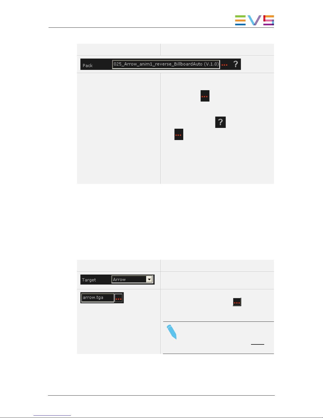
Field/Button Description
The Pack field displays the graphic pack
assigned to the tool.
The ellipsis icon next to the Pack field
enables you to select the graphic pack you want
to work with.
The interrogation mark next to the ellipsis
icon gives you access to a PDF document
that includes:
• a static preview of the animation,
• the modifiable parameters,
• the associated commands on the Remote
Panel.
Target Area
In the Target area, you can refine the definition of the various components included in the
graphic pack you have selected in the Pack area. The components of a graphic pack are
called ‘targets’.
This step is optional since you can decide to keep all predefined values of the selected
graphic pack. The parameters you can customize will depend on the type of target you
are editing:
Field/Button Description
Drop-down field to select the type of target you
want to edit in the selected graphic pack.
Field to select the template image sequence you
will use. When you click on the , the
application directly points to the folder where the
.tga template sequences are stored.
Note
The template image sequence needs
to be in uncompressed TGA 32-bit
format.
Page 62

EVS Broadcast Equipment SA
Issue 1.70.A February 2014
54 Configuration
Note
The tool 033_Score and logos provides the possibility to load a .tga image
sequence.
Main Parameters
The main parameters associated to the loaded target are displayed on the left. These
parameters are described in the table below.
Field/Button Description
Specifies the color of the selected component.
Click the color frame to open the color palette,
and select the requested color.
Slider that allows defining the transparency of
the Alpha layer of the selected component.
The Alpha field allows defining the transparency
for individual components, whereas the black
level of the chroma key allows defining the
general transparency for the offside line
animation.
Displays the result of the color selection (RGB)
for the loaded target.
Displays the result of the alpha channel selection
for the loaded target.
Drop-down field to select the font to be used for
the text to be displayed.
Note
The fonts need to be copied to the Windows Fonts directory for them to be
available in Epsio.
They are not saved in the graphic pack itself. They consequently need to be
available on any Epsio workstation where the graphic pack using the specific
font will be installed.
Page 63

USER MANUAL Epsio Live 1.70
Configuration 55
Specific Parameters
Other more specific parameters associated to the loaded target are displayed in a table
on the right:
You cannot modify the values directly in the table.
You can however click or double-click the values in the table, which displays respectively
a slider or a dialog box to enable you to modify the value.
For more information, refer to the section 2.5.4 ‘How to Customize a Graphic Suite’, on
page 56.
2.5.3 How to Create a Graphic Suite
This procedure explains how to create a graphic suite to which you will associate the
predefined graphic packs you will need to create animations.
To create a graphic suite, proceed as follows:
1. In the TOOLS tab, Graphics area in Epsio, click the Edit radio button in the Tools
working mode area:
The Generic tab is displayed in the lower part of the Tools tab:
2. In the Graphic area in Epsio, Generic tab, click the button.
3. In the Save As window, type the name you want to give to your graphic suite in the
File Name field, and click Save.
This creates a graphic suite (.egs file) you will associate the graphic packs to.
4. In the Generic tab, click the arrow in the Tool drop-down field,
and select the tool to be included in your graphic suite.
Page 64

EVS Broadcast Equipment SA
Issue 1.70.A February 2014
56 Configuration
5. In the Generic tab, click the ellipsis icon on the right of the Pack field, and select
the default graphic pack (.egp file) you want to use.
A static preview of the animation, with the related parameters and associated
commands on the various graphic packs are available as you click the icon.
6. Repeat the steps 4 and 5 for each available tool.
7. Click the Save button to save the changes in the graphic suite you have created.
The suite whose name is displayed at the top of the Generic tab is the loaded graphic
suite, in other words the suite that will be taken into account as you create animations in
Epsio.
If you want to customize the graphic packs of your graphic suite, refer to the section 2.5.4
‘How to Customize a Graphic Suite’, on page 56.
2.5.4 How to Customize a Graphic Suite
Introduction
Once you have created your graphic suite by assigning predefined graphic packs (as
described in section 2.5.3), you can customize your graphic packs as follows:
1. In the TOOLS tab, Generic tab, and Graphic area, click the Load button and select
the graphic suite you want to edit.
The selected graphic suite is loaded.
2. If you want to save your customized graphic suite under a new name, the Save As
button and assign a name to the customized graphic suite.
Otherwise, the changes will be saved in the loaded graphic suite.
3. In the Tool area, select the tool you want to edit the target parameters for from the
Tool drop-down field:
4. In the Target area, select the target you want to customize in the Target drop-down
field:
,
The parameters associated to the loaded target are displayed below the Target field,
or in the table on the right.
Page 65

USER MANUAL Epsio Live 1.70
Configuration 57
5. To edit one of the main parameters displayed on the left of the table, you can directly
edit the field values:
• For a color selection, click the colored square and specify the RGB values.
• For a slider, move the slider to the left or right to respectively decrease or
increase the parameter value.
• For other fields, proceed as usual.
• Click the Save button regularly to save your changes.
6. To edit one of the parameters displayed in the table, proceed in one of the following
ways:
• To modify the value using a slider, click once the requested parameter.
This displays a slider below the table:
Move the slider to the requested value. The value is automatically modified in the
table. See also the note below.
• To directly type the requested value in a field, double-click the requested
parameter:
This opens a dialog box similar to the following one:
Click in the field, type the requested parameter value and click OK.
7. Click the Save button to save the changes in the graphic suite.
Note
The displayed slider range corresponds to a portion of the full available
range, and depends on the selected value.
If the requested value is not available in the slider range, move to the nearest
value available, select another field, then select again the requested field.
The slider range will be adapted and will include the requested value.
Page 66

EVS Broadcast Equipment SA
Issue 1.70.A February 2014
58 Configuration
2.6 Defining the Replay settings
Introduction
The Replay settings are applied by default when you play back the offside line animation
once it has been created.
How to Modify the Replay Settings
You can modify the Replay settings as follows:
1. From the main menu, press SHIFT+D (EPSIO) to enter the Epsio menu.
2. From the offside line mode, press SHIFT+MENU to display the Replay settings
screen:
Replay Settings p. 1.1
[F1] Pause Duration: 019 Frame(s)
[F2] Fade In Duration: 015 Frame(s)
[F3] Fade Out Duration: 015 Frame(s)
[F4] Preroll Duration: 02 Second(s)
[F5] Default playback speed : 100%
[F6] Clear All Events
[Menu] Quit [F0] Next
3. Select the function key related to the setting you want to modify.
4. Jog the wheel to set the requested value.
5. Press MENU to leave the Replay settings screen.
Page 67

USER MANUAL Epsio Live 1.70
Configuration 59
Replay Settings
The following table explains briefly the replay settings:
Setting Description
Pause Duration Duration of the pause before displaying the animation.
The pause duration can be between 0 and 300 frames. It is
recommended to have a minimum value of 3 frames.
Fade In Duration Duration of the fade effect at the beginning of the animation.
The fade in duration can be between 0 and 300 frames.
Fade Out Duration Duration of the fade effect at the end of the animation.
The fade out duration can be between 0 and 300 frames.
Preroll Duration Number of seconds where the clip is paused before the
animation when the user presses the Last Cue button.
The Preroll value can be between 1 and 60 seconds.
Default Playback Speed Default playback speed applied during the animation when
the user presses the PLAY button.
The default playback duration can be between 0 and 300%.
Clear All Events Clears all the offside animations that have been saved
under the F1 to F10 function keys.
Page 68

EVS Broadcast Equipment SA
Issue 1.70.A February 2014
60 Creating Graphic Animations
3. Creating Graphic Animations
3.1 General Information
3.1.1 Prerequisites
Before you can create and play back an offside line or live animation in Epsio, you must
have performed the following configuration steps, which are described in the
Configuration chapter:
• Calibrating the cameras
• Configuring the chroma key and selecting a chroma key profile
• Creating, customizing and loading the requested graphic suite
• Defining the replay settings
3.1.2 Overview on the Epsio Menu
From the main operational menu, press SHIFT+D to access the Epsio menu:
Offside
Arrow
Circle
Graphics
ChromaK
OSD
Graph
<-- Calib
Calib -->
Page 69

USER MANUAL Epsio Live 1.70
Creating Graphic Animations 61
Epsio Main Menu
ChromaK
OSD
Graph
<-- Calib
Calib -->
Detect
The Epsio main menu contains the following commands:
Command Description
Graph Allows the user to display or hide the Epsio animation that has
been created. The Graph command is active when you enter the
Epsio menu.
ChromaK Allows the user to enter the Chroma Key menu, in which you can
configure the chroma key definition.
Refer to the section 2.4.2 ‘Accessing the Chroma Key Menus’,
on page 38.
OSD Allows displaying or hiding the OSD information on the output
monitor. By default, the OSD information is displayed.
<-- Calib Allows moving to the previous calibration angle in the Calibration
tab of Epsio.
Calib--> Allows moving to the next calibration angle in the Calibration tab
of Epsio.
Detect The playfield limits are automatically detected when one of the
live tools is active. If the automatic detection fails, pressing
Detect forces again the automatic detection mechanism. This
option is only available with the live tools.
Secondary Menu
The secondary menu contains the various tools you can use in Epsio.
To access or leave the secondary menu, press the MENU key on the Remote Panel.
Offside
Arrow
Circle
Graphics
To activate a tool in the secondary menu, click the key corresponding to the requested
tool: Offside (A), Arrow (B), Circle (C), Graphics (D).
Page 70

EVS Broadcast Equipment SA
Issue 1.70.A February 2014
62 Creating Graphic Animations
3.2 Creating an Offside Animation
3.2.1 Remote Menu with Offside Feature Active
If you want to create an offside line, you need to do the following before you enter the
Epsio menu:
• Position on the frame where you want to create an offside line animation.
From the main operational menu, press SHIFT+D to enter the Epsio menu:
Offside
Arrow
Circle
Graphics
ChromaK
OSD
Graph
<-- Calib
Calib -->
The Epsio menu is displayed with the Offside tool active.
If the Offside tool is not active, you can activate it as you activate a live tool (See section
3.3.1 ‘How to Activate a Live Tool‘, on page 65.
The Graph feature is active by default.
The Mark key is blinking red on the LSM Remote Panel.
The virtual playfield is displayed on the operator’s PGM.
Note
If the playfield limits are automatically detected, the virtual playfield lines are
red. Otherwise, the virtual playfield lines will be white. In this case, you first
need to validate the playfield limits manually.
3.2.2 How to Validate the Playfield Limits
Introduction
Based on the calibration performed, the playfield limits are automatically detected and
matched to the virtual playfield when you enter the offside line mode. In this case, the
virtual playfield lines are displayed in red.
If the image on which you want to create your offside line is slightly blurred, or does not
display enough lines on the playfield for the automatic detection to work properly, the
virtual playfield will be made of white lines.
If the auto-detection of the playfield does not work (white lines) or if the virtual playfield
lines are not perfectly matched to the real playfield, you first have to validate the playfield
limits. This action consists of repositioning the virtual playfield limits onto the real playfield
limits.
Page 71

USER MANUAL Epsio Live 1.70
Creating Graphic Animations 63
Procedure
To validate the playfield limits, proceed as follows:
1. When you have entered the offside line mode, right-click one of the points on the
virtual field. This can be a virtual point you have added during the calibration.
2. Drag the virtual field to match the real playfield.
3. Release the mouse.
4. Use the mouse wheel to adjust the zoom.
The real playfield limits have been validated, and the virtual playfield lines are now
displayed in red on the monitor.
3.2.3 How to Create an Offside Line Animation
To create an offside line animation, proceed as follows:
1. In the operational menu, click A, B, C or D to select the camera that you want to use
to create the offside line animation:
Rst Cam
Local
Sync Prv
Epsio
Cam A
Cam B
2. Pause on the offside frame.
3. Press SHIFT+D to access the Epsio menu.
ChromaK
OSD
Graph
The GRAPH feature is automatically active (black background).
4. Looking at the operator’s PGM, position the offside line using the mouse or the jog.
5. Press MARK. This has the following effects:
• The virtual playfield is removed on the operator’s PGM.
• A snap is created on the director’s preview.
6. If you want to adjust the position of the offside line, press CLEAR.
The nowline returns to the position on the record train that was selected when you
entered the Epsio menu in step 3.
Repeat step 5 to mark a new position for the beginning of the offside line animation.
7. Go back to a position before the TC where you have marked the start of the offside
sequence:
• Press Last Cue to go back to the predefined pre-roll
• Jog to the requested position
8. To play the offside line sequence back with the offside line animation, do one of the
following:
• Press PLAY to play back at the predefined playback speed.
• Use the lever.
The director’s PGM and the operator’s PGM are running and pause when it gets to
the beginning of the offside line animation. The pause duration depends on the
Pause Duration setting. The animation is then played.
Page 72

EVS Broadcast Equipment SA
Issue 1.70.A February 2014
64 Creating Graphic Animations
9. After the animation has been played, you can use the lever or press PLAY to carry on
playing the record train.
10. Press RECORD to go out of the Epsio menu.
If the operator keeps the Graph command active, the graphic will be played when the clip
will go on air.
If the director invalidates the offside line on his PGM, the operator can press A again to
deactivate the Graph command. When the clip will go on air, the offside sequence will be
played out ‘clean’, without the offside line animation.
3.2.4 Saving Positions of Offside Line Animations
You can save the position of maximum ten offside line animations using the function keys
F1 to F10.
How to Save the Position of an Offside Line
When you have marked your offside line using the MARK key, you can save its position
by pressing the F_ keys on the Remote Panel.
How to Recall the Position of an Offside Line
To recall the offside line position you have previously saved under a function key, you first
need to enter the Epsio menu and activate the offside line mode.
Recall the position by pressing the F_ key corresponding to the saved position of the
requested offside line.
Once you have recalled the position, you can press MARK to redefine the offside line
animation at the position you have recalled.
Page 73

USER MANUAL Epsio Live 1.70
Creating Graphic Animations 65
3.3 Creating a Live Animation
3.3.1 How to Activate a Live Tool
To activate a live tool in the Epsio menu, you need to do the following:
1. Press MENU to enter the secondary menu.
2. Select the key corresponding to the requested live tool:
Offside
Arrow
Circle
Graphics
ChromaK
OSD
Graph
<-- Calib
Calib -->
Detect
The secondary menu closes automatically.
The selected live tool is displayed on a black background, and the Detect command is
displayed in the main menu.
3.3.2 How to Create An Arrow or Circle Animation
When you are in the Epsio main menu, and have selected the live tool you want to use,
proceed as follows to create a live animation:
3. Looking at the operator’s PGM, press D (Detect) to refresh the automatic field
detection based on the live feed.
The virtual playfield is matched to the real playfield.
4. Position the mouse pointer where you want the arrow to start or the center of the
circle to be displayed.
The live animation is applied to the current timecode of the video material.
5. You can then perform one of the following actions:
• Click again on the field with the mouse to reposition the animation.
• Press Mark to remove the virtual playfield in red wireframe.
• Press A (Graph) to hide the animation (if requested).
• Press the TAKE key to toggle between the arrow and the circle animation.
3.3.3 Using the Graphics Tool in Epsio
As soon as the Graphics live tool is activated in the secondary menu, the graphic defined
in the graphic suite will be displayed continuously as soon as the user comes back to the
Epsio main menu, and as long as the Graph command is active.
Page 74

Page 75

Page 76

 Loading...