

Page 1
User’s Manual
Version 1.63 - May 2011
Offside Line and Live Tools
Page 2

Page 3

Epsio Version 1.63 – User’s Manual
EVS Broadcast Equipment – May 2011
Issue 1.63.C
I
COPYRIGHT
EVS Broadcast Equipment – Copyright © 20 10-11. All rights reserve d.
DISCLAIMER
The information in this manual is furnished for informational use only and subject
to change without notice. While every effort has been made to ensure that the
information contained in this user manual is accurate, up-to-date and reliable,
EVS Broadcast Equipment cannot be held responsible for inaccuracies or errors
that may appear in th is publication.
IMPROVEMENT REQUESTS
Your comments will help us improve the quality of the user documentation. Do not
hesitate to send improvement requests, or report any error or inaccuracy on this
user manual by e-mail to
doc@evs.tv.
REGIONAL CONTACTS
The address and phone number of the EVS headquarters are usually mentioned in
the Help > About men u in the user interface.
You will find the full list of addresses and phone numbers of local offices on the
following page on the EVS website:
http://www.evs.tv/contacts
USER MANUALS ON EVS WEBSITE
The latest version of the user manual, if any, and other user manuals on EVS
products can be found on the EVS download center, on the following webpage:
http://www.evs.tv/downloadcenter
Page 4

Issue 1.63.C
Epsio Version 1.63 – User’s Manual
EVS Broadcast Equipment – May 2011
II
Page 5

Epsio Version 1.63 – User’s Manual
EVS Broadcast Equipment – May 2011
Issue 1.63.C
III
Table of Contents
TABLE OF CONTENTS ................................................................................................. III
WHAT’S NEW ................................................................................................................. 1
1. OVERVIEW ............................................................................................................. 2
1.1 PRODUCT DESCRIPTION .......................................................................................................... 2
1.2 CABLING ..................................................................................................................................... 2
1.3 EPSIO USER INTERFACE .......................................................................................................... 4
1.3.1 Overview ................................................................................................................................. 4
1.3.2 Operating Monitor ................................................................................................................... 5
1.3.3 Server Information Area .......................................................................................................... 5
1.3.4 Camera Angle List................................................................................................................... 7
1.3.5 Zoom ....................................................................................................................................... 7
1.3.6 Tabbed Area ........................................................................................................................... 7
1.3.7 Menu Bar ................................................................................................................................ 7
2. CONFIGURATION ................................................................................................ 10
2.1 OVERVIEW ................................................................................................................................ 10
2.1.1 C onnec t ion S te ps .................................................................................................................. 10
2.1.2 C onfi gur a ti on Ste ps ............................................................................................................... 10
2.1.3 Saving and Managing the Configuration ............................................................................... 11
2.2 CONNECTING EPSIO AND EVS SERVER ............................................................................... 12
2.2.1 Starting the EVS Server Application ...................................................................................... 12
2.2.2 Epsio Settings on Remote Panel........................................................................................... 12
2.2.3 Activating the Connection Between Epsio and the EVS Server ............................................ 13
2.2.4 C heck ing t he Vi de o Feeds .................................................................................................... 15
2.3 CALIBRATING THE CAMERAS ................................................................................................ 17
2.3.1 Introduction ........................................................................................................................... 17
2.3.2 Calibration Tab ...................................................................................................................... 17
2.3.3 How to Calibrate the Cameras .............................................................................................. 23
2.3.4 Snapshots for Calibration ...................................................................................................... 25
2.3.5 Recommendations for Matching the Virtual Playfield to the Real One .................................. 30
2.3.6 Testing your Calibration ........................................................................................................ 34
2.3.7 Adding Virtual Points ............................................................................................................. 37
2.4 CONFIGURING THE CHROMA KEY ......................................................................................... 39
2.4.1 Gener al Information .............................................................................................................. 39
2.4.2 Ac ces si ng the Chr om a Key M enus ....................................................................................... 40
2.4.3 C hr oma Key Par am e ter s ....................................................................................................... 42
2.4.4 C hr oma Key Edi t Sc reen on the Remote Panel .................................................................... 44
2.4.5 Chroma Key Tab in Epsio ..................................................................................................... 45
2.4.6 Methods and Recommendations for the Chroma Key Definition ........................................... 48
2.4.7 How to Configure a Chroma Key Based on an Automatic Chroma Key ................................ 49
2.4.8 How to Configure a Chroma Key Based on an Area Selected on the Playfield ..................... 50
2.5 ADDING AND CUSTOMIZING THE GRAPHIC SUITE .............................................................. 51
2.5.1 Graphic Suite Definition and Components ............................................................................ 51
2.5.2 Tools Tab .............................................................................................................................. 52
Page 6

Issue 1.63.C
Epsio Version 1.63 – User’s Manual
EVS Broadcast Equipment – May 2011
IV
2.5.3 How to Create a Graphic Suite.............................................................................................. 56
2.5.4 How to Customize a Graphic Suite ....................................................................................... 57
2.6 DEFINING THE REPLAY SETTINGS ........................................................................................ 59
3. CREATING GRAPHIC ANIMATIONS ................................................................... 61
3.1 GENERAL INFORMATION ........................................................................................................ 61
3.1.1 Prerequisites ......................................................................................................................... 61
3.1.2 Overview on the Epsio Menu ................................................................................................ 61
3.2 CREATING AN OFFSIDE ANIMATION ..................................................................................... 63
3.2.1 Remote Menu with Offside Feature Active ............................................................................ 63
3.2.2 How to Validate the Playfield Limits ...................................................................................... 63
3.2.3 How to Create an Offside Line Animation ............................................................................. 64
3.2.4 Saving Positions of Offside Line Animations ......................................................................... 65
3.3 CREATING A LIVE ANIMATION ................................................................................................ 66
3.3.1 How to Activate a Live Tool ................................................................................................... 66
3.3.2 How to Create An Arrow or Circle Animation ........................................................................ 66
3.3.3 Using the Graphics Tool in Epsio .......................................................................................... 66
Page 7

Epsio Version 1.63 – User’s Manual
EVS Broadcast Equipment – May 2011
Issue 1.63.C
1
Improvement of the ‘Detect’ function available in the
Possibility to save and recall up to ten offside line
What’s New
The following table descr ibes the sections updated to reflect the n ew and modified
features on Epsi o 1.63 (compared to Eps io 1.60).
In the user manual, the icon has been added on left margin to highlight
information on new and updated features.
Click the section number (or the description) in the table to jump directly to the
corresponding section.
Section Description
Section 1.3.3 Changes in the Server Information Area
Section 1.3.7 New commands in the me nu bar
Section 2.2.2 New Epsio setting ‘Aut o Mark’
Section 2.3.5 Improvements in the way you adjust the virtual points
described in the section ‘Addit ional Tips’
Section 2.4.5 New Apply butto n in the Chroma Key tab
Section 2.5.4 Slider to edit the to ol parameters displayed in the table
Section 3.1.2
Epsio main menu.
Section 3.2.3 Possibility to clear the mark set for the offsi de animation.
Section 3.2.4
animations.
The following table lists sections which have been added or modified to improve
the content of the us er manual:
Section Description
Section 2.3.4
and 2.3.5
New sections on calibr ating the main camera:
• Main Camera Calibration
• Virtual Points to be Matched for a Main Camera
Section 2.3.7 Improved secti on ‘Adding Virtual Points’
Section 2.5.4 New procedure ‘How to Customize a Graphic Suite’
Page 8

Issue 1.63.C
Epsio Version 1.63 – User’s Manual
EVS Broadcast Equipment – May 2011
2
1. Overview
1.1 PRODUCT DESCRIPTION
Epsio is a graphics solution integrated into the MulticamLSM that allows the
operators to control graphic animations, such as offside line, graphic overlays,
arrows or circles, using the LSM Remote Panel.
It can be used with the EVS XT family servers and works with Multicam, from
version 10.2.30 onwards.
Before the event, the use r performs the initial calibration, where the images of the
playfield are matched with predefined angles into the system. Based on this
calibration, Epsio is able to instantly and automatically recognize the playfield
during actions when the playfield is clearly visible on the video signal. The user
will also define the chroma key, which means the range of colors on the video
signal where the graph ic animations will be incrusted.
The operator can then trigger the animation in a one-second operation, using the
jog wheel of the LSM Remote Panel.
The producer can automatically see a screenshot with the graphic animation, and
decide whether or not to play out the entire action with the effects.
Important
If you want to use the live tools in Epsio, you need to have the Live
Tools license inst alled in XSecure.
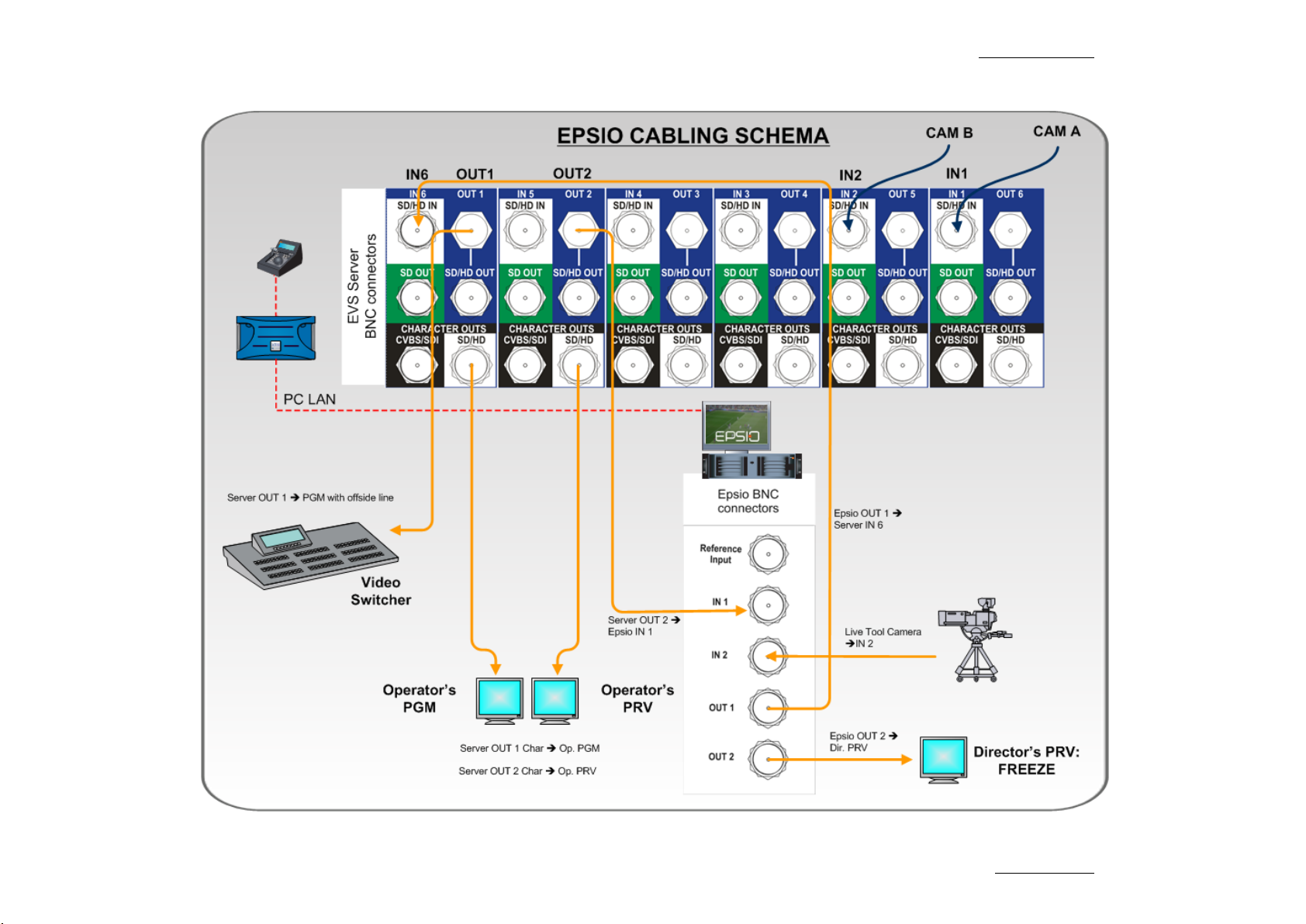
1.2 CABLING
The schema on the following page shows how the Epsio workstation and the EVS
server BNC cables should be connected:
Page 9
Epsio Version 1.63 – User’s Manual
EVS Broadcast Equipment – May 2011
Issue 1.63.C
3
Page 10
Issue 1.63.C
Epsio Version 1.63 – User’s Manual
EVS Broadcast Equipment – May 2011
4
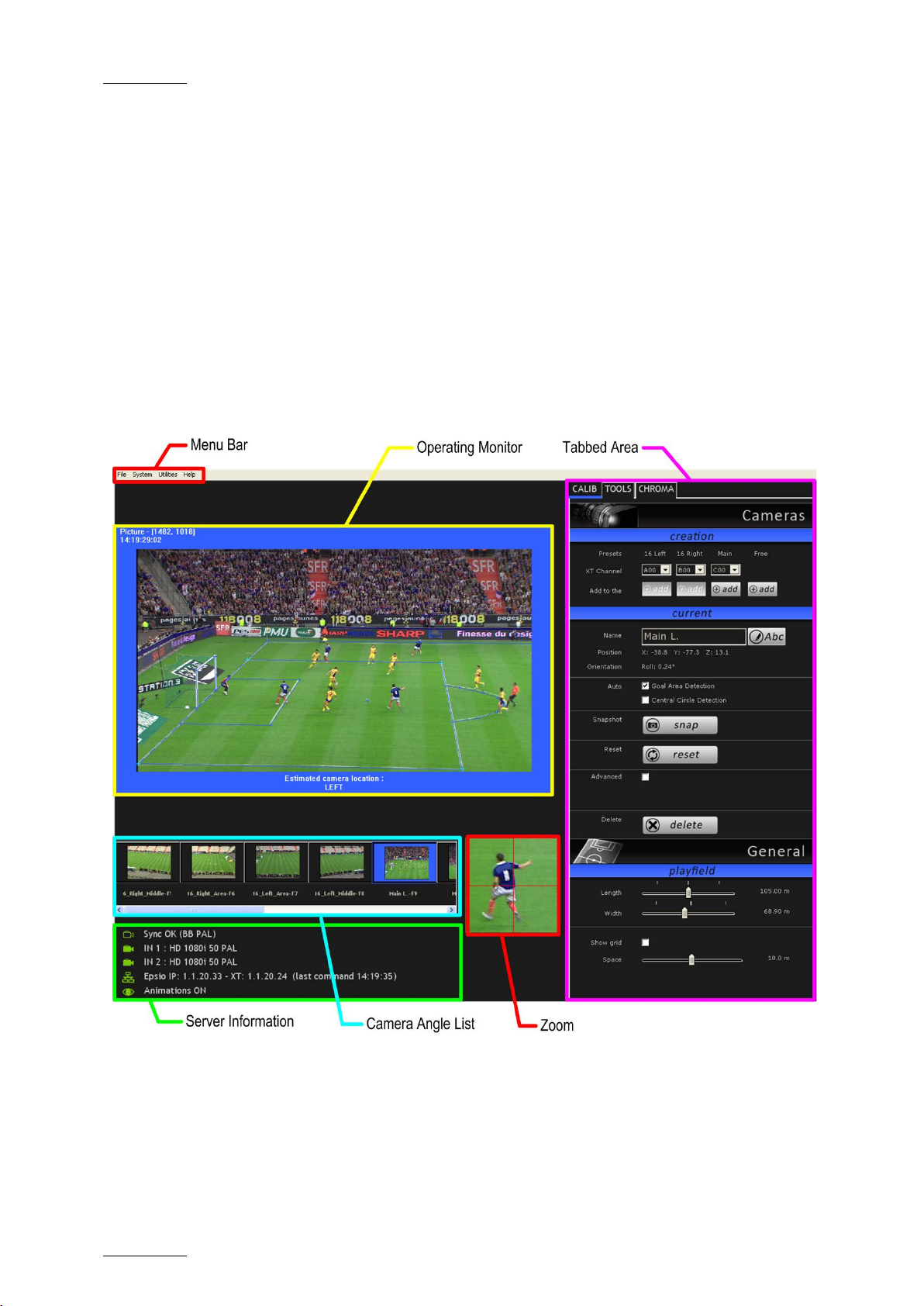
1.3 EPSIO USER INTERF ACE
1.3.1 OVERVIEW
You will access Epsio by clicking the Epsio icon on the desktop, or via the Start
menu in Program Files > EVS Broadcast Equipment > Epsio > Epsio.
The following screenshot provides an overview on the Epsio user interface,
highlighting the various areas that will be explained in more details in the various
sections:
For more information on the LSM Remote Panel, refer to the Multicam Operational
User Manual.
Page 11
Epsio Version 1.63 – User’s Manual
EVS Broadcast Equipment – May 2011
Issue 1.63.C
5
Note
When the offside line mode is active on the LSM Remote Panel, you
cannot use the mouse o utside the operating monit or in Epsio.
To be able to move the mouse in the whole Epsio window, do one of the
following:
• In Epsio, press on the keyboard.
• Press RECORD on the LSM Remote Panel to go out of the offside line
mode.
1.3.2 OPERATING MONITOR
The operating monitor shows the video signal coming from the EVS server and
received on the Epsio connector IN1. It allows the users to visualize the
configuration action they perform, or the ani mations they cre ate.
The image on the monitor is surrounded by a colored frame, which varies
depending on the tab open in the tabbed area on the right of the Epsio main
window:
• Blue frame when t he Calibration tab is op en
• Red frame when the Tools tab is open
• Green frame when t he Chroma tab is open
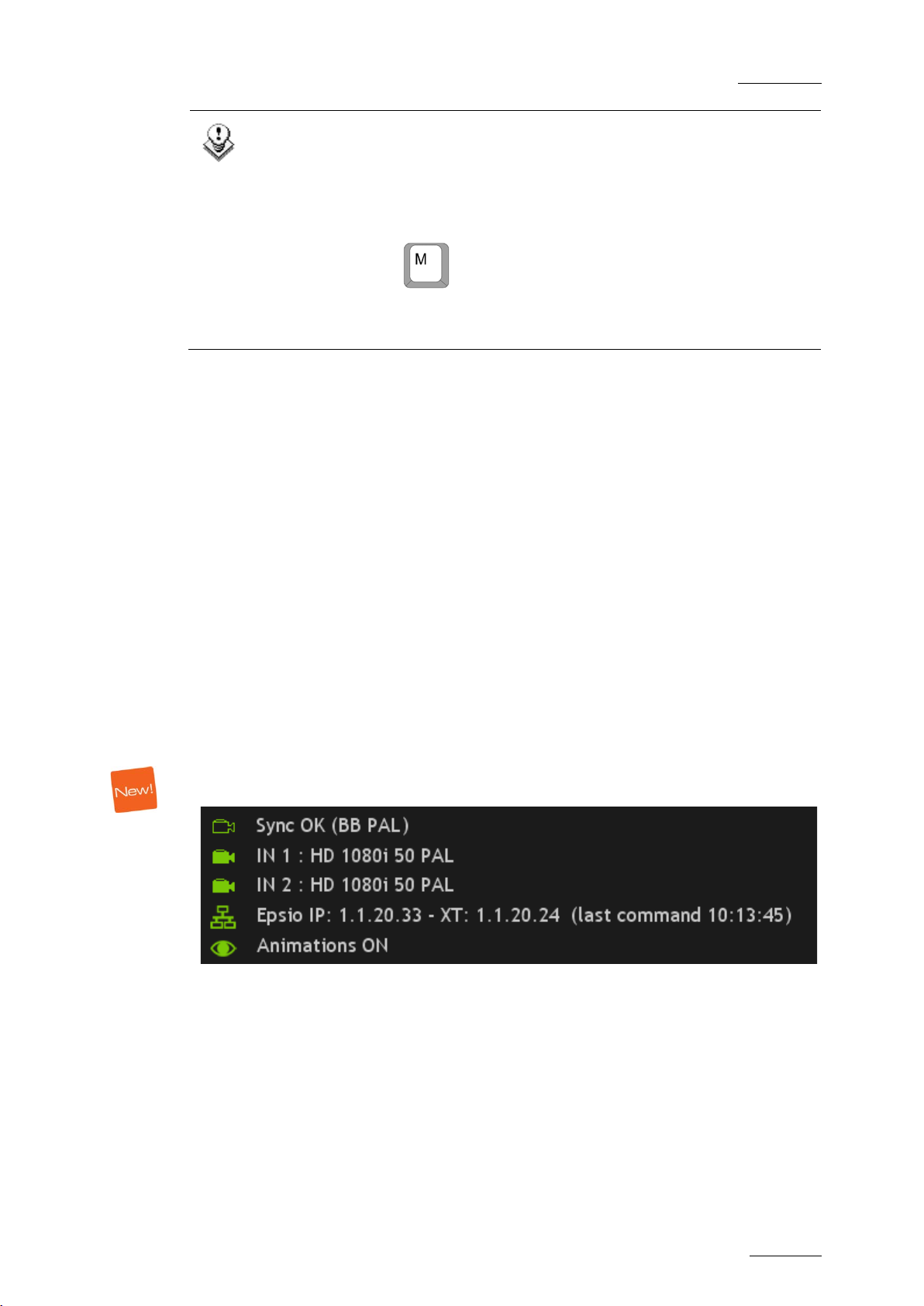
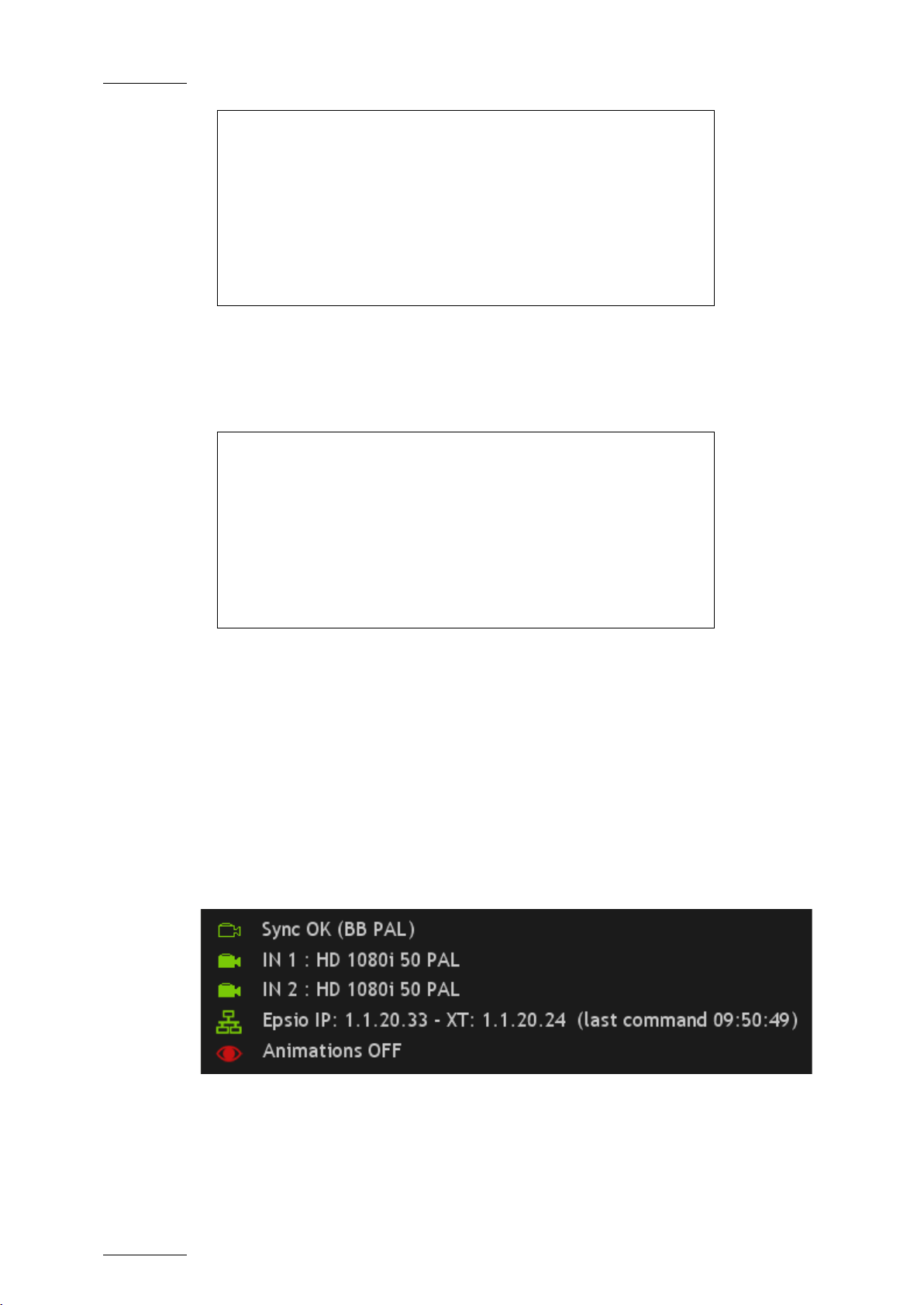
1.3.3 SERVER INFORMATION AREA
The Server Informatio n area is located at the left bottom of the Epsio main wind ow
and provides the foll owing information:
The following table describes the information available in the Server Information
area, from the top to the bottom line.
When both systems are correctly connected for both Epsio inputs, the icons in
front of the first f our lines are green. Other wise, they are red.
Page 12
Issue 1.63.C
Epsio Version 1.63 – User’s Manual
EVS Broadcast Equipment – May 2011
6
the received signal corresponds to the
or not, the following information will be
the video
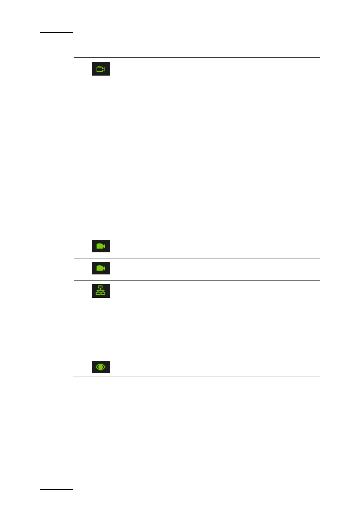
# Icon Description
1.
Check that the received blackburst signal corresponds to the video
format selected in th e Epsio Configurator.
Depending on whether
specified video format
displayed:
• NO SYNC
• SYNC OK
• WRONG SYNC
The values between brackets show the requested format, based on
the format defined in the Epsio Configurator, and can be one of the
following:
• BB PAL
• BB NSTC
• Tri-Level 1080 i50
• Tri-Level 1080 i60
• Tri-Level 720p 50
• Tri-Level 720p 60
2.
3.
4.
Check that the Epsio IN1 connector correctly receives
signal from the EVS server i n the specified video format.
Check that the Epsio IN2 connector correctly receives from the EVS
server or a cam era in the specified video format.
Epsio and EVS server IP addresses
Time when the last comm and was executed on the server .
You need to press SHIFT+D when you open Epsio and enter the
Epsio menu on the Remote Panel to force the system to check the
communication via the Et hernet network, and confirm the connection.
In the course of operat ions, the icon will not automatica lly turn red if
you lose the connection. You need to recheck the communication by
entering again the Ep sio menu on the Remote Panel.
5.
Information on whether the animation is visibl e or not.
Page 13

Epsio Version 1.63 – User’s Manual
EVS Broadcast Equipment – May 2011
Issue 1.63.C
7
1.3.4 CAMERA ANGLE LIST
The Camera Angle list shows a thumbnail for each camera angle that has been
defined and/or calibrated. You can select a camera angle by clicking the
thumbnail. This Camera Angle list is particularl y useful in the Calibrat ion phase.
When the camera angle has only been created, but not calibrated yet, the
thumbnail shows a grey background and the virtual playfield.
When the camera angle has been calibrated, the thumbnail shows the frame
grabbed from the video signal.
1.3.5 ZOOM
The zoom area shows a zoomed display of the area around the mouse pointer on
the operating monitor. It mainly allows p erforming the calibration, as well as other
actions, in a ver y précised way.
1.3.6 TABBED AREA
The tabbed area gives access to the following tabs, in which you can configure
Epsio and select the animations you will perfo rm:
• The CALIB tab allow s the users to define and calibrate the camera an gles.
See also the section 2.3.2 ‘Calibration Tab ’, on page 17.
• The TOOLS tab allows the users to select the animations they want to perform,
and refine the settin gs for these animations .
See also the section 2.5.2 ‘Tools Tab’ , on page 52
• The CHROMA tab allows the users to define the chroma key layer that will
define how the offsid e line animation will b e displayed.
See also the section 2.4.5 ‘Chroma Key T ab in Epsio’, on page 45.
1.3.7 MENU BAR
FILE MENU
The File menu includes the commands for saving and managing the Epsio
configuration. They are described in the section 2.1.3 ‘Saving and Managing the
Configuration’, on pag e 11.
Page 14

Issue 1.63.C
Epsio Version 1.63 – User’s Manual
EVS Broadcast Equipment – May 2011
8
that allows
You will find more information on the Epsio
file that contains
SYSTEM MENU
The System menu contai ns the commands described below:
Command Description
Video Configuration
This opens the Epsio Configurator tool
checking the video fe eds.
Configurator in the section 2.2.4 ‘Checking the Video
Feeds’, on page 15.
Support > Keep for Stu dy This command generates a ZIP
information. This is typically used by the support staff
to investigate a snap on which the det ection would not
work. You need to be i n the Epsio menu on the Remote
Panel for the ZIP file to be generate d.
The generated ZIP file is stored in C:\EvsLogs\Epsio
and contains the following files:
• snapshot of the video sig nal when the user enter the
Epsio menu
• the XML files containing calibration information and
a parameter descriptio n of the snapshot
• the EPSIO.cfg file that contains the configuration
definition, and allows the support team to recreate
your configuration on the support setup.
Support > Update
Support Files
This command generates the EPSIO.cfg file that
contains the configuration definition, and allows the
support staff to investigate an issue with Epsio on
your setup by recreating your configuration on the
support setup.
The file is stored in C:\EvsLogs\Epsio.
Support > Update PCX3
Information
This command enables the users to test the video
board. Note that the test will generate disturbances on
the video for some sec onds.
The Help > About window opens and displays the test
results. A popup will be displayed if the results do not
correspond to acceptab le values.
Advanced > Setup
External Renderer
Advanced setup parameter. Please contact EVS for
more details.
Advanced > Reset 2CPU Advanced parameters only for support purposes, and
in coordination with the support team.
Page 15

Epsio Version 1.63 – User’s Manual
EVS Broadcast Equipment – May 2011
Issue 1.63.C
9
manual, in
active in
UTILITIES MENU
The Utilities menu con tains the commands describ ed below:
Command Description
Save as JPG Using this command or t he keyboard shortcut CTR L+J,
you will take a snapsh ot in JPG of the video output
OUT1. It can t hen be used as an example.
The file is stored in the folder: C:\EvsLogs\Epsio, and
is named [Snapshot], followed by the date a nd time
when the snapshot was taken.
Save as BMP Same as the ‘Save as J PG’ command, except that the
generated screenshot i s a .BMP.
HELP MENU
The Help menu contains the commands described below:
Command Description
Help
This provides a link to the Epsio user
English and in other available languages.
About This opens the About w indow that features information
about:
• the Epsio version and licenses
• the version and specifications of the graphic board
(PCX3)
• the support’s email addresses and phone numbers
• a summary of the keyboard shortcuts
Epsio.
Page 16

Issue 1.63.C
Epsio Version 1.63 – User’s Manual
EVS Broadcast Equipment – May 2011
10
2.1 OVERVIEW
The configuration in order to use Epsio with an EVS server has to be performed in
the Epsio application or on the EVS server side (via the EVS menu and the LSM
Remote Panel), depe nding on the configuration st ep.
2.1.1 CONNECTION STEPS
Before you can actually configure Epsio, you first need to set up Epsio and the
EVS server to communicate with e ach other:
# Step Where? See section
2. Configuration
1. Starting the appropriate EVS server
application
2. Activating th e connection between
Epsio and the EVS server
3. Checking the video feeds Epsio 2.2.4
2.1.2 CONFIGURATION STEPS
Once Epsio and the EVS server are properly connected, you can perform the
actual configuration steps.
# Step Where? See section
1. Calibratin g the cameras Epsio 2.3
2. Configurin g the Chroma Key settings Remote Panel
3. Customizing and loadin g the graphic
suite
EVS server 2.2.1
Remote Panel 2.2.3
2.4
or Epsio
Epsio 2.5
4. Defining t he Replay settings Remote Panel 2.6
Page 17

Epsio Version 1.63 – User’s Manual
EVS Broadcast Equipment – May 2011
Issue 1.63.C
11
2.1.3 SAVING AND MANAGING THE CONFIGURATION
The commands available in the File menu allow you to save and manage the
configuration you will perform. The configuration, which includes the camera
calibration and the chroma key definition, is saved in a configuration file that is
made up of two .xml fi les:
• A file contai ning the playfield distance s and all camera angle defi nitions.
This file is ‘name’.xml where <name> is the name the user gives to the
configuration when it is saved for the firs t time.
• A file contai ning the chroma key configu ration.
This file is ‘name’.CK.
In the File menu, you have access to the foll owing commands:
Command Use
New Use this command before you start a new calibrati on.
This creates a new empty configuration file that you can save
throughout the calibr ation process.
Load Use this command to poi nt to and load an existing configuration file.
Save Use thi s command to save your calibra tion while you define it.
It is recommended to save the configuration after each calibration
step.
Save As Use this command if you want to save the open configuration file
into a new name, for backup purposes, or to start a new calibration
from an existing one.
The configurations are stored by default i n the following location :
C:/Program Files/EVS Broadcast Equipment
/Epsio/Config.
Page 18

Issue 1.63.C
Epsio Version 1.63 – User’s Manual
EVS Broadcast Equipment – May 2011
12
key in the Operational menu gives
2.2 CONNECTING EPSIO AND EVS SE RVER
2.2.1 STARTING THE EVS SERVER APPLICATION
When using Epsio with a n EVS server, you need to run a server application:
• with at least 2 recorder channel s and 2 player cha nnels
• in a Multicam LSM base config uration.
For more information on starting an EVS application, refer to the EVS Menu
section in the Techni cal Reference Software man ual.
2.2.2 EPSIO SETTINGS ON REMOTE PANEL
The settings to activate the Epsio mode, and specify the default Epsio tool are
available on page 9.2 of the Setup menu:
Special Effect p.9.2
[F1]Paint/Target OSD Mon itoring: SD
[F2]Offside Line: On
[F3]External Offs ide: On
[F4]IP Address: x xx.xxx.xxx.xxx
[F5]Default tool: Offside
[F6]Auto Mark: Of f
[Menu]Quit [Clr+F _]Dft [F9]PgUp [F0]PgDn
These settings ar e described below:
Setting Possible
Values
[F2] Offside
Line
[F3] External
Offside
On, Off
(default)
On, Off
(default)
Description
Activates the offside lin e feature, whatever
internal or e xternal.
When the parameter is s et to ‘On’, the External
Offside paramet er is displayed.
Enables the control of Epsio from the Remote
Panel.
When the setting is set to ‘Off’, the offside line
feature built in the EVS server is active. The
SHIFT+D
access to the Epsio menu.
When the setting is se t to ‘On’, the Epsio
application i s active. The SHIFT+D key in the
Operational menu g ives access to the Epsio
menu. The IP Address a nd Default Tool
parameters are display ed.
Page 19

Epsio Version 1.63 – User’s Manual
EVS Broadcast Equipment – May 2011
Issue 1.63.C
13
s parameter
key on the
Setting Possible
Values
[F4] IP
Address
[F5] Default
Tool
[F6] Auto
Mark
xxx.xxx.xxx.xxx When the Epsio con nection is enabled with the
Offside, Arrow,
Circle,
Graphics
On, Off When the Auto Mark parameter is set to ‘On’, a
Description
External Offside p arameter, the IP Address of
the Epsio wor kstation has to be enter ed in this
parameter to allow the communication between
the EVS server and the Epsio workstation.
When the Epsio connection is enabled with the
External Offside parameter, thi
specifies the tool to be activated by default in
the Epsio menu on the Remote Panel.
cue point is created on the record train where
and each time the user enters the Epsio menu.
Such cue points are the same as the cue points
added manually using the Mark
Remote Panel, and are managed the same way.
For more information on cue points, refer to the
Multicam Operation manu al.
2.2.3 ACTIVATING THE CONNECTION BETWEEN EPSIO AND THE EVS SERVER
To activate the offside line mode and the external offside line mode, proceed as
follows:
1. From the Main menu, select Setup by pressing SHIFT + D to enter the Setup
menu.
2. Press the F9 key to go to the Special Effects settings, and then F0 to go
down to page 9.2:
Special Effect p.9.2
[F1]Paint/Target OSD Monitoring: SD
[F2]Offside Line : Off
[Menu]Quit [Clr+ F_]Dft [F9]PgUp [F0]PgD n
3. Press F2 to access the Offside Line setting and rotate the jog dial to set it to
‘On’.
This will display the External Offside setting.
Page 20
Issue 1.63.C
Epsio Version 1.63 – User’s Manual
EVS Broadcast Equipment – May 2011
14
Special Effect p.9.2
[F1]Paint/Target OSD Mon itoring: SD
[F2]Offside Line: On
[F3]External Offs ide: Off
[Menu]Quit [Clr+F _]Dft [F9]PgUp [F0]PgDn
4. Press F3 to access the External Offside setting and rotate the job dial to set
it to ‘On’.
This will display the IP Address setting.
Special Effect p.9.2
[F1]Paint/Target OSD Mon itoring: SD
[F2]Offside Line: On
[F3]External Offs ide: On
[F4]IP Address: x xx.xxx.xxx.xxx
[F5]Default tool: Offside
[F6]Auto Mark: Of f
[Menu]Quit [Clr+F _]Dft [F9]PgUp [F0]PgDn
5. Enter the IP address o f the Epsio workstation as follows:
After entering the num ber for an octet wit h the function keys, valid ate by
pressing ENTER on the LSM Remote Panel .
6. Press MENU twice to go out of the Setup menu .
7. Press SHIFT+D t o enter the Epsio menu.
nd
The Epsio workstation should now be connected. In Epsio, the 2
and 3rd lines
(which specify whether the corresponding IN connectors receive the video signal
from the EVS server in the requested video format) should have green icons, as
well as the 4
th
line (which specifies the IP add resses):
For more information on this Server Information area, refer to the section 1.3.3
‘Server Informatio n Area’, on page 5.
Page 21
Epsio Version 1.63 – User’s Manual
EVS Broadcast Equipment – May 2011
Issue 1.63.C
15
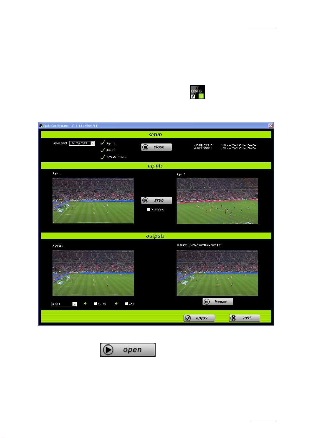
2.2.4 CHECKING THE VIDEO FEEDS
Once you have switched on the Epsio workstation for an event, you should check
that you correctly get the feeds before you launch the Epsio software. The Epsio
Configurator helps you detect and check the feed s.
To check the video fee ds, proceed as follows:
1. To open Epsio Configuration, double click on the desktop or select
Epsio Configurator via the Start menu in Program Files > EVS Broadcast
Equipment > Epsio > Ep sio Configurator.
2. In the Setup group box, select the Video Format you are worki ng with.
3. Click the button.
Epsio checks the forma t you have selected is com patible with the format us ed
by the EVS server.
If the right form at is selected, Epsio automa tically grabs and displays an
image of the video si gnals.
Page 22

Issue 1.63.C
Epsio Version 1.63 – User’s Manual
EVS Broadcast Equipment – May 2011
16
4. As you check the incoming and outgoi ng signals, you can perform the follow ing
actions to help you i dentify the signals:
o To check the incoming signals, you can click the Grab button to grab the
current image delivere d to the incoming feeds.
o To check the output signal from the OUT1 connector, you can either change
the signal sent to OUT1 by selecting In 1, In 2, or Bars, or add the PC time or
a logo display t o the output signal.
o To check the current output signal from the OUT 2 connector, you can click
the Freeze button to refresh t he video display corresponding to output 2.
5. When you have checked the incoming and outgoing video signals, click the
Apply button.
6. Click Exit.
Page 23

Epsio Version 1.63 – User’s Manual
EVS Broadcast Equipment – May 2011
Issue 1.63.C
17
the camera
2.3 CALIBRATING THE CAMERAS
2.3.1 INTRODUCTION
In Epsio, calibrating the cameras consists of positioning a virt ual playfield in a 3D
environment to match the position of the actual playfield used for a given event.
You calibrate the came ras in the Calibration t ab in Epsio.
OFFSIDE LINE CALIBRATION
When you use the offside line too l, you usually cal ibrate two 16-meter cameras for
an event: a left-angle camera and a right-angle camera. However, Epsio allows
you to use other cameras.
You calibrate each 16-meter camera on two angles: looking at the goad area, and
at the central circle.
LIVE TOOLS CALIBRATION
When you use the live tools, yo u calibrate the camera that is directly conn ected to
Epsio via the IN2 Connector. For this physical camera, you will calibrate a main
camera in Epsio. The three angles (left, center and right) are automatically added
to the Camera Angle Li st when you add a mai n camera in the Calibration t ab.
Important
Only calibrate your cameras when you have validated
position, height and orientation. These should no longer change after the
calibration.
2.3.2 CALIBRATION TAB
OVERVIEW
The following table gives a short explanation on each area of the Calibration tab
displayed below:
Area Description
Camera Creation This area allows you to add cameras, and assign them to a
recorder channel on an EVS server.
See also the section ‘Camera Creati on Area’, on page 19.
Current Camera This area allows you to perform several actions on the
selected camera.
See also the section ‘Current Camera Area’, on page 20.
Page 24

Issue 1.63.C
Epsio Version 1.63 – User’s Manual
EVS Broadcast Equipment – May 2011
18
Area Description
General This area all ows you to modify the de fault playfield size (10 5
meters by 68 meters), as well as to display and/or modify
the grid of the virtu al playfield.
See also ‘General Area’, on page 22.
Page 25

Epsio Version 1.63 – User’s Manual
EVS Broadcast Equipment – May 2011
Issue 1.63.C
19
CAMERA CREATION AREA
This area allows you to add camer as, and assign them to a recorder chann el on an
EVS server.
Field Description
Buttons that allow the user to define a new camera in
the system. Several pr eset cameras are availab le:
• The Add button below the 16 Left label allows
adding a 16-me ter left-angle camera.
It creates two cameras angles (goal and center) .
• The Add button below the 16 Right label allows
adding a 16-me ter right-a ngle camera.
It creates two cameras angles (goal and center) .
• The Add button below the Main Label allows adding
a camera for the live tools.
It creates three camer a angles (left, center, right).
• The Add button below the Free Preset label should
be used to create any other camera.
It creates one camera angle.
Field to associate the recorder chan nel of the EVS
server to the created camera. The field value i s made
up as follows:
• The first let ter is the camera letter on the server
• Keep the last two digits as is (00).
By default, the A channel is assigned to the 16-meter
left camera, and the B channel is assigned to the to
the 16-meter ri ght camera.
Page 26

Issue 1.63.C
Epsio Version 1.63 – User’s Manual
EVS Broadcast Equipment – May 2011
20
CURRENT CAMERA AREA
This area allows you to perform several actions on the current camera. The
current camera is the on e selected in the Camera Angle list. Th is is displayed in a
blue frame in the Camera Angle list.
Field Description
Displays the name of t he camera selected in
the Camera Angle li st below the operating
monitor.
The camera name can on ly be modified using
the button.
Rename button used to rename the cam era.
Non-editable field that summarizes the
parameters for the came ra position.
Non-editable field that summarizes the
parameters for the came ra orientation.
Check box to be tic ked when you calibrate a
camera (left, right, cent ral or free) to specify
that the angle of detection corresponds to the
goal area.
For the automatic detecti on to work properly,
the image should clear ly display the goal area.
Page 27

Epsio Version 1.63 – User’s Manual
EVS Broadcast Equipment – May 2011
Issue 1.63.C
21
angle to define the horizontal
Orientation: mix of Y axis and pan, to
Field Description
Check box to be ticked when you calibrate a
camera (left, right, cent ral or free) to specify
that the angle of detectio n corresponds to the
central circle.
For the automatic detection to work properly,
the image should clear ly display the central
circle.
Snap Button used t o grab a new image of the
playfield on which th e calibration of the camer a
will be based. It gra bs the current frame on t he
video input 1 (PGM1).
Button used to reinit ialize the display of the
virtual playfield f or the selected camera.
Button used to delete the selected camera.
Check box to display o r hide the two fields
below used for fine-tuning the curr ent camera
position.
Field that allows sele cting the position
parameter you want to m odify among the
following ones:
• X axis: north/south axi s to define the camera
position
• Y axis: east/west axis to define the camera
position
• Z axis: up/down axis to define the camera
position
• Pan:
orientation of the camera on its position, in
this case from 85° to 125°
• Tilt: angle to define the vertical orientation
of the camera on its position, in this case
from 60° to 100°.
• Roll: angle to define the camera orientation
along its longitudinal axi s, in this case from 20 to +20°
•
simulate a rotation around the center of the
playfield
Once the position para meter is selected, you
can change its value dragging the slider to the
right or left.
Page 28

Issue 1.63.C
Epsio Version 1.63 – User’s Manual
EVS Broadcast Equipment – May 2011
22
GENERAL AREA
This area allows you to modify the size of the virtual playfield, and whether/how
grids will be displayed on the virtual playfi eld.
Field Description
Length Slider to modify the default playfield length (105 meters ).
Width Slider to modify the default playfield width (70 meters).
Show Grid Check box to display o r hide the grid on the virt ual playfield
Space When the grid is d isplayed, the space slider makes it possible
to modify the l ine space in the grid.
Page 29

Epsio Version 1.63 – User’s Manual
EVS Broadcast Equipment – May 2011
Issue 1.63.C
23
of the real playfield
2.3.3 HOW TO CALIBRATE THE CAMERAS
Note
The calibration steps explained in the sections below illustrate the
calibration of the two 16-meter cameras used with the offside line tool.
However, the same procedure applies to the calibration of the free
camera for the live tools .
Once Epsio is open, you calibrate the various cameras in the CALIB tab, in the
following way:
1. Add a virtual camera for each physical camera to be calibrated, by clicking
the Add butt on corresponding to the requested camera in the Creation area:
The camera angles to be calibrated for the corresponding camera preset are
added as frames includ ing the virtual playfie ld in the Camera Angle lis t:
2.
Using the Preview channel, make snapshots
corresponding to each calibration angle in the f ollowing way:
a. In the Camera Angle list in Epsio, click the camera angle to which you
want to associate a sn apshot.
b. Pause on the requested frame in the previe w channel.
Page 30

Issue 1.63.C
Epsio Version 1.63 – User’s Manual
EVS Broadcast Equipment – May 2011
24
and drag it to the corresponding position on the real
c. Click in the Current area in Epsio.
For more information, refer to the section 2.3.4 ‘Snapshots for Calibration,
on page 25.
3. For each camera angle, perform a rough calibration, by matching four non-
contiguous virtual anchor points to the real position in the playfield as
follows:
• Right-click a virtual anchor point (crosses on the lines) on the requested
camera angle
playfield, then relea se.
A light blue line is drawn between the virtual point and the matched point on
the snapshot:
Once the fourth point h as been matched, the virtual play field is automatically
superimposed t o the snapshot.
For more information on the four points to be matched, and on the possible
actions with the mouse, refer to the section 2.3.5 ‘Recommendations for
Matching the Virtual Playfield to the Real One’, on page 30.
4. To refine the calibration of a virtual point, do t he following:
a. Position the mouse around the virtual point (it is surrounded by a red
circle).
b. Use the Arrow keys on the keyboard to adj ust the virtual point.
5. Adjust the playfi eld size if necessary:
• Check that touchlines are not too long or too small on the four calibration
angles, and if necess ary adjust the playfield widt h.
• Check that the central circle is not too large or small on the two central
calibration angles, a nd it necessary adjust the p layfield length.
Click the menu File > Save to save the configuration. The default location
6.
where configurations are stored is C:/Program Files/
EVS Broadcast Equipment/Epsio/Config.
Page 31

Epsio Version 1.63 – User’s Manual
EVS Broadcast Equipment – May 2011
Issue 1.63.C
25
The camera angles defined in Epsio are now associated to snapshots of the
real playfield and saved in a configuration file. You can load them back via
the File > Load menu. See also the section
Configuration’, on pag e 11.
7. Use varied test snapshots to make sure the calibration is acceptable as a
whole. If necessary, perform some adjustments by repositioning only the
anchor points initial ly matched in step 3.
For more information on the calibration tests, see the section 2.3.6 ‘Testing
your Calibration’, on page 34.
8. On a shot that includes the 16-meter line, and part of the central circle, a dd
virtual points for offsid e shots where playfield lines would not be visible.
For more information on additional virtual points, see the section 2.3.7
‘Adding Virtual Points’, on page 37.
2.3.4 SNAPSHOTS FOR CALIBRATION
2.1.3 ‘Saving and Managing the
16-METER CAMERA CALIBRATION
Introduction
For each 16-meter camera used for the offside feature, you need to take two
snapshots correspondin g to each camera angle:
• Goal area
• Central circle
Important
Keep the following in mind when you select the fra me you will use:
• A playfield is naturally curved, whereas the Epsio virtual field is made
up of straight lines.
• A very wide shot is very likely to distort the image, which will in tensify
the curved effect of the field.
Goal Area Cali bration
The snapshot for the goal area of the left or right 16-meter cam era should show:
• the whole left or right penalt y area (respectively) with the 16-meter and 6-meter
lines
• the goal line al ong the goal area,
• part of each touc hline on both sides of the playfield.
Page 32

Issue 1.63.C
Epsio Version 1.63 – User’s Manual
EVS Broadcast Equipment – May 2011
26
Important
The touchlines should be parallel to the horizontal borders of the frame,
and the zoom should keep the distortions of touchlines as low as
possible.
Figure 1: Good Snapshot for the calibration of the goal area with a left 16-meter camera
Figure 2: Good Snapshot for the calibration of the goal area with a right 16-meter camera
Page 33

Epsio Version 1.63 – User’s Manual
EVS Broadcast Equipment – May 2011
Issue 1.63.C
27
Central Circle Calibration
The snapshot for the central circle of the left or right 16-meter camera should
show:
• the whole central circle (not necessarily the ful l central line),
• the 16-meter l ine of the left or right penalty area (respectively), and the penalty
arc.
• part of each touc hline on both sides of the playfield.
Figure 3: Good Snapshot for the calibration of the central circle with a left 16-meter camera
Figure 4: Good Snapshot for the calibration of the central circle with a right 16-meter camera
Page 34

Issue 1.63.C
Epsio Version 1.63 – User’s Manual
EVS Broadcast Equipment – May 2011
28
MAIN CAMERA CALIBRATION
You need three calibra tion shots to calibr ate the central camera:
• Left penalty area
• Central circle
• Right penalty area
Important
Keep the following in mind when you select the fra me you will use:
• A playfield is naturally curved, whereas the Epsio virtual field is made
up of straight lines.
• A very wide shot is very likely to distort the image, which will in tensify
the curved effect of the field.
Goal Area Cali bration
The snapshots for the goal area of the main camera should show the following
elements:
• the central li ne
• the whole left /right penalty area (depending on the shot)
The shot should be as close as possible while containing the above-mentioned
elements.
Figure 5: Good Snapshot for the calibration of the left goal area with a main camera
Page 35

Epsio Version 1.63 – User’s Manual
EVS Broadcast Equipment – May 2011
Issue 1.63.C
29
Figure 6: Good Snapshot for the calibration of the right goal area with a main camera
Central Circl e Calibration
The snapshot of the c entral circle area should s how the following elements :
• the whole central circle
• the upper and lowe r touchlines
• both upper ends o f the left and right 16-meter lin e (if possible).
Figure 7: Good Snapshot for the calibration of the central circle with a main camera
Page 36

Issue 1.63.C
Epsio Version 1.63 – User’s Manual
EVS Broadcast Equipment – May 2011
30
2.3.5 RECOMMENDATIONS FOR MATCHING THE VIRTUAL PLAYFIELD TO THE REAL ONE
VIRTUAL POINTS T O BE MATCHED FOR A 16-METER CAMERA
The following screenshots highlight the four virtual points you are advised to use
for each camera angle of a left 16-meter camera to perform a n optimal calibration.
Use equivalent virtual points for the ri ght 16-meter camera.
Goal Area
Four virtual points are used as calibration points on goal area of the left or right
16-meter camera:
• both ends of the 16-mete r line
• both ends of the 6-meter l ine
Page 37

Epsio Version 1.63 – User’s Manual
EVS Broadcast Equipment – May 2011
Issue 1.63.C
31
Central Circl e
Four virtual points ar e used as calibration poi nts:
• both intersec tions between the central lin e and the central circ le
• both upper ends o f the 16-meter lines
Page 38

Issue 1.63.C
Epsio Version 1.63 – User’s Manual
EVS Broadcast Equipment – May 2011
32
VIRTUAL POINTS T O BE MATCHED FOR A MAIN CAMERA
The following screenshots highlight the virtual points you are advised to use for
each camera angle of a main camera to perform a n optimal calibration.
Goal Area
Six virtual points ar e used as calibration points on each shot:
• both ends of the 16-mete r line
• both ends of the 6-meter l ine
• both intersec tions between the central li ne and the central circ le
Page 39

Epsio Version 1.63 – User’s Manual
EVS Broadcast Equipment – May 2011
Issue 1.63.C
33
Central Circl e
The following virtual points are used as calibra tion points:
• both intersec tions between the central lin e and the central circ le
• both upper ends o f the 16-meter lines
• intersections between the central line and the touchlines (if nec essary)
POSSIBLE ACTIONS USING THE MOUSE
Here are the possible actions you can perform in t his step:
• To select a vir tual point, right-click on it.
• To delete a virtual point , click on it.
• To add a virtual point, press CTRL + click on the virtual field at the position
where the point should be added.
• To remove a vir tual point you have added, click on it.
ADDITIONAL TIPS
Here are the following tips to help you in this step:
• Once you have selected a virtual point, you can adjust its positio n in one of the
following ways:
o Pressing the arrow keys on the keyboard f or small increments
o Pressi ng simultaneously SHIFT a nd the arrow keys on the keyboard for bigger
increments.
• When the mouse po inter is close to a virtua l point, a red circle surrou nds it, and
the arrow keys on the keyboard are automatically activated to enable you to
adjust the point.
Page 40

Issue 1.63.C
Epsio Version 1.63 – User’s Manual
EVS Broadcast Equipment – May 2011
34
• The four anchor points you use to calibrate a camera angle should not be
aligned.
• Always match th e points to the same edge of the lines.
• You can use more t han 4 points to perform the calibration.
• If the 2
excellent, you can use the position parameters (x,y,z) of this camera angle for
the central cir cle calibration of the same camera.
nd
and 3rd tests of the goal area calibration for a given camera are
2.3.6 TESTING YOUR CALIBRATION
GENERAL TEST FOR A 16-METER CAMERA
Once you have calibrated all your camera angles, it is recommended to test them
using test snapshots of the playfield.
A general and quick t est consists of drawing an offside line, and rolling it over the
calibration shots, to ensure that the offside line matches the foll owing lines of the
field:
• the 16-meter line
• the 6-meter line
• the half-w ay line
Systematic tests based o n test snapshots are explained in details below.
TESTING TH E GOAL AREA
1st Test
Using the same view as your calibrati on shot, take an offsi de shot.
Check that the 16-meter line and 6-meter line are cor rectly matched.
If necessary, reposit ion the faulty anchor poi nts.
2nd test
Move the camera to the bottom corner arch without changing the zoom.
Page 41

Epsio Version 1.63 – User’s Manual
EVS Broadcast Equipment – May 2011
Issue 1.63.C
35
Check that the 16-meter line and 6-meter line are cor rectly matched.
3rd test
Move the camera back to the goal area, keeping the 6-meter and 16-meter lines.
All lines must match.
If the tests are not satisfactory, refine the calibration by matching several
calibration points again. Each time you modify your calibration, you need to
perform the tests again.
When you do not achieve perfect results using calibration points, you can modify
the advanced se ttings for the camera positio n in the Current area to fine-tune your
calibration. These parameters allow a global modification of the calibration for
each camera, taking into account the X, Y, Z position, as well as the orientation
with the pan, tilt and roll angles. See also the description of the Advanced group
box in the section ‘Current Camer a Area’, on page 20.
Page 42

Issue 1.63.C
Epsio Version 1.63 – User’s Manual
EVS Broadcast Equipment – May 2011
36
TESTING TH E CENT RAL CIRCLE
All lines must be correctly matched on the calibration shot. Besides this, you
should test three add itional test shots:
1st test
Using the same view as your calibration shot.
Check that the central ci rcle is correctly matched, and t hat the borders of the half-
way line are corre ctly matched.
If necessary, reposit ion the faulty anchor poi nts.
2nd test
Center the camera on t he half-way line to see the whole line.
When you draw an offside line on this shot, the virtual line should touch both ends
of the half-way line. Due to the natural playfield curve, the offside line may not
fully correspond to t he half-way line ar ound the middle of the li ne.
Page 43

Epsio Version 1.63 – User’s Manual
EVS Broadcast Equipment – May 2011
Issue 1.63.C
37
3rd test
Move and zoom the came ra to view the 6-m eter line, and part of th e half-way line.
Use this test shot to add your additional virtual p oints.
2.3.7 ADDING VIRTUAL POINTS
PURPOSE
When Epsio is not able to automatically detect the playfield limits, the operator
has to validate the playfield limits manually as ex plained in the section 3.2.2 ‘How
to Validate the Playf ield Limits’, on page 63.
In extreme cases, shots do not display any playfield line. This is the case, for
example, with a close-up between the centra l line and the 16-meter li ne, as shown
below:
In such a situation, you can use additional points, which are not included in the
original mapping model , to validate the playfi eld limits.
It is recommended to add the additional poi nts at this stage of the calibration.
Page 44

Issue 1.63.C
Epsio Version 1.63 – User’s Manual
EVS Broadcast Equipment – May 2011
38
RULES
Follow the rules specified below whe n you add virtual points:
• The additional virtual points are only added to the calibration of the camera
angle you are edit ing. You will not be able to use the addi tional virtual points on
other camera angles.
• Choose the additional virtual points using positions that you will easily identify
during the live event, that is to say the stadium geometry: first step of the
terracing, static ban ners around the field, etc.
• Add at le ast two additional virtua l points.
• To add virtual points for the central circle, for example, you can use a shot
similar to the snapsho t used for the 3
rd
calibratio n test of the central circ le.
PROCEDURE
To define an additional virtual point, press CTRL + click where you want to add
the point on the cali bration shot.
TEST
To test the addit ional virtual points, p roceed as follows:
1. Select a shot on which you barely see the playfield lines (typically with the
upper part of the hal f-way line and a portion of th e 16-m eter line).
2. Press SHIFT + D on the Remote Panel.
3. Reposition manually th e virtual playfield on the shot u sing the visible playfield
lines.
You can then check that the additional virtual points are correctly placed, and
match the requested position. Otherwise, go back to the calibration shot, and
modify the position o f the wrong additional poi nt.
Page 45

Epsio Version 1.63 – User’s Manual
EVS Broadcast Equipment – May 2011
Issue 1.63.C
39
2.4 CONFIGURING THE CHROMA KEY
2.4.1 GENERAL INFORMATION
CONCEPT O F CHROMA KEY
The chroma keying is a technique for compositing two images or frames together
in which a color (or a range of colors) from the main image (video signal) is
removed (or made transparent), revealing another image behind it. The key is the
image that punctures t hrough the image of the video signal.
In Epsio, you select the green color of the playfield (or a range of green) and
replace it by the key layer. The key layer will defi ne how the offsi de line animation
will be displayed:
• All that is white in the key layer will n ot be incrusted.
In the final result, the key is transparent and the main image will show.
• All that is black in the key layer will be incrusted with the offside line anim ation.
In the final result, the main image is covered by the offside line animati on.
• The more an area is black, th e more the incrusted materi al will show.
In summary, when you define the chroma key, you define the color or color range
in the video signal t hat will be replaced by t he offside line animatio n.
Page 46

Issue 1.63.C
Epsio Version 1.63 – User’s Manual
EVS Broadcast Equipment – May 2011
40
Rst Cam
Local
Sync Prv
Epsio
Cam A
Cam B
ChromaK
OSD
Graph
<--Calib
Calib -->
Chroma key Server Edit Screen
Auto
Save
Save As
Quit
Profile 1
Profile 2
Profile 3
Profile 4
IMPACT OF LIGHT CONDITIONS
As the chroma key depends on the light, it is recommended to configure the
chroma key 30 minutes before the match to get the closest to the light conditions
that will prevail dur ing the match.
For a match during the day, you should perform two chroma key configurations:
one for light, one fo r dark, to allow you to cope with shadows on the p layfield.
In case you have a bright light, but a large shadow across the field (for example
the top of the stadium roof structure), you can also make a chroma key matching
light and shadows, in which case the player s would be under the graphics.
For a match during the night, you can configure a chroma key as soon as the sun
is down and the stadi um lights are on.
RECOMMENDATIONS
You can define th e chroma key:
• in the chroma key edit screen on the LSM Rem ote Panel
• in the CHROMA t ag in Epsio.
It is recommended to configure the chroma key using the Remote Panel. For this
reason, we will provide minimal information on the chroma key definition using the
CHROMA tab in Epsio.
2.4.2 ACCESSING THE CHROMA KEY MENUS
ON THE LSM REMOTE PANEL
To access the Chroma Key edit screen on the LSM Remote Panel, proceed as
follows:
1. From the operational me nu in PGM/PRV mode, press the SHIFT+D key to enter
the Epsio main menu:
The Epsio menu open s:
2. In the Epsio menu, press SHIFT+B to enter the Ch roma Key edit screen.
F1: X F5: X Transition
F2: Y F6: Y Transition
F3: Width F7: Black Level
F4: Height F8: Toggle View
You will confi gure the chroma key from this menu.
Page 47

Epsio Version 1.63 – User’s Manual
EVS Broadcast Equipment – May 2011
Issue 1.63.C
41
IN EPSIO
In Epsio, you can con figure the chroma key in the CHROMA tab:
Page 48

Issue 1.63.C
Epsio Version 1.63 – User’s Manual
EVS Broadcast Equipment – May 2011
42
2.4.3 CHROMA KEY PARAMETERS
You can create and manage up to four chroma key definitions from the LSM
Remote Panel, or in Epsio, using the chroma ke y profiles.
The various chroma key parameters allow you to define or refine a chroma key
profile.
The representation of the chroma key definition in a color space will help you
visualize the range o f colors taken into accoun t in the chroma key def inition.
REPRESENTATION OF TH E CHROMA KEY IN EPSIO
A YUV color space is displayed on the CHROMA tab in Epsio to represent the
color range selected i n the chroma key:
The chroma key definit ion is represented as f ollows on the color space:
• The black box in the color space corresponds to the colors that are totally
removed on the chroma k ey layer (black).
• The colors between the black and white boxes in the color space correspond to
the transition color range, in other words to the colors that will be more or less
removed on the chroma k ey layer. The white bo x is clearly displaye d in Epsio.
• The colors outside the white box in the color space correspond to the colors
that are not removed on the chroma key layer (white) .
REPRESEN TATION OF THE CHROMA KEY ON THE MONITOR
A YUV color space is displayed on the top left corner of the monitor to represent
the color range selected in the chroma key. It contains additional scales, with
‘sliders’ to reflect the hue, saturation and black level (or brightness) of the
selected color range. The grey box displayed on the color space represents the
selected color range.
Page 49

Epsio Version 1.63 – User’s Manual
EVS Broadcast Equipment – May 2011
Issue 1.63.C
43
DEFINITI ON OF THE CHROMA KEY PARAMETERS
The chroma key parameters are explained in the t able below:
Parameter Description
RGB Hue Value Definitio n
X Moves left and right the color range in the col or space.
Y Moves up and down the color range in the color space.
Tolerance Definition
Width (W) Widens or narrows the color range on the X axis in the
space.
Height (H) Widens or narrows the color range on the Y axis in the
space.
Transition Definiti on
X Transition (TX) Widens or narrows (on the X axis) the color range that will
be more or less punctu red when defining the key l ayer.
Y Transition (TY) Widens or narrows (on the Y axis) the color range that will
be more or less punctu red when defining the key l ayer.
Black Level Adjusts the level of transparency of the graphic animation,
in other words defines how strong the animation will be
displayed.
Page 50

Issue 1.63.C
Epsio Version 1.63 – User’s Manual
EVS Broadcast Equipment – May 2011
44
Chroma key Server Edit Screen
Auto
Save
Save As
Quit
Profile 1
Profile 2
Profile 3
Profile 4
chroma key
2.4.4 CHROMA KEY EDIT SCREEN ON THE REMOTE PANEL
INTRODUCTION
You define and manage the chroma key definition from the Chroma Key edit
screen. When you a re in this screen, the Edit mode is directly active.
F1: X F5: X Transition
F2: Y F6: Y Transition
F3: Width F7: Black Level
F4: Height F8: Toggle View
In addition, the co lor space is also d isplayed at the top left of the operator’s PGM
monitor when you define the chroma key. It allows you to visualize the range of
colors taken into acc ount in the chroma key defini tion.
For more information re fer to the sections:
• Section ‘Available Commands’ (page 44)
• Section ‘Chroma Key Parameters’ (page 42)
• Section ‘How to Configure a Chroma Key Based on an Automatic Chroma Key’
(page 49)
• Section ‘How to Configure a Chroma Key Based on an Area Selected on the
Playfield (page 50)
AVAILABLE COMMANDS
The following table describes the various commands and parameters available on
the chroma key edit sc reen on the Remote Panel:
Field area or button Description
Chroma Key
Parameters (F1-F7)
Toggle View (F8) Toggles between the key layer view (white & black), and
Parameters to define the color range taken into account
in the chroma key definition.
For more information on the var ious parameters, refer the
section ‘Chroma Key Par ameters’, on page 42.
image view (color) on the operator’s PGM monitor.
Auto (SHIFT+A) Press this key to perform an automatic
definition that you can then save in one of the available
profiles.
Save (SHIFT+B) Press this key to save the changes into the currently
loaded profile (highlighted in black on the Chroma Key
Page 51

Epsio Version 1.63 – User’s Manual
EVS Broadcast Equipment – May 2011
Issue 1.63.C
45
edit screen.
Field area or button Description
Save As (SHIFT+C) Press this key, followed by a key corresponding to a
chroma key profile to save the currently loaded chroma
key definition under the selected chroma key pro file.
Quit (SHIFT+D) Press this key to leav e the chroma key edit scr een.
Profile 1 (A) to Profile
4 (D)
Four profiles under which the chroma key definitions can
be saved.
2.4.5 CHROMA KEY TAB IN EPSIO
TAB OVERVIEW
You can also refine t he chroma key definition in t he CHROMA tab in Epsio.
The following schema sh ows the various areas in t he CHROMA tab.
Page 52

Issue 1.63.C
Epsio Version 1.63 – User’s Manual
EVS Broadcast Equipment – May 2011
46
Page 53

Epsio Version 1.63 – User’s Manual
EVS Broadcast Equipment – May 2011
Issue 1.63.C
47
FIELDS AN D COMMANDS IN THE CHROMA TAB
The following table de scribes the field boxes and buttons o n the tab:
User Interface
Description
Element
Profiles area
EVS Profiles list Lists the chroma key prof iles available in the Chroma Key edit
screen of the LSM Remote Panel. The chroma key preview is
only available once a snapshot has been taken using the
Snap button:
• Clicking the profile loads a preview of the chroma key on
the preview area.
Preview Shows a preview of the chroma key profile selecte d in the list.
Snap Clicking this button snaps the current image from PGM1 and
loads it onto the ope rating monitor.
Load Clicking this button loads the selected profile in the Settings
area.
Save Clicking this button saves the chroma key values defined for
the chroma key profile loaded into the CHROMA tab.
Apply Clicking this button activates t he loaded chroma key profile in
Epsio.
This corresponds to the chroma key profile selection in the
Chroma Key edit screen of the Remote Panel.
Settings area
Color space Shows the color range for the chroma key definit ion.
Also refer to the section ‘Chroma Key Parameters’, on page
42.
Adjustment
sliders
Each slider allows modify ing one of the chroma key parameter
of the loaded chroma k ey profile.
Also refer to the section ‘Chroma Key Parameters’, on page
42.
Note
When you are refining the Chroma key in Epsio, you can toggle between
the chroma key and the image showing the final incrustation by rightclicking the mouse.
Page 54

Issue 1.63.C
Epsio Version 1.63 – User’s Manual
EVS Broadcast Equipment – May 2011
48
How to
2.4.6 METHODS AND RECOMMENDATIONS FOR THE CHROMA KEY DEFINITION
METHODS
There are several ways to configure your chrom a key.
This section will explain the two main me thods:
• Defining a chr oma key based on an automati cally generated chroma key.
• Defining a chr oma key based on an area se lected on a playfield.
STEPS
In both methods, you need to go through the follo wing steps:
1. Creating an offside l ine.
2. Accessing the Chroma Ke y edit screen.
3. Generating the initial chroma key definition.
4. Saving the initial chroma key definition in a profile.
5. Opening the ch roma key profile.
6. Refining the init ial chroma key definition.
7. Saving the final chroma key definition in the loaded profile or in a new one.
RECOMMENDATIONS AND TIPS
In the Chroma Key edit screen, the F8 function allows you to toggle between the
chroma key layer (white/black display) and the representation of the final
incrustation on the video signal (color display).
It is recommended to:
• Use the chroma key layer to define the chroma key parameters from F1 to F6.
• Toggle to the final incrustation to refine the black level parameter (F7).
Note
If you cannot see the representation of the final incrustation, this means
you need the limits of your playfield could not be automa tically validated.
You need to validate them manually. See the section 3.2.2 ‘
Validate the Playfield Limits’, on page 63.
Page 55

Epsio Version 1.63 – User’s Manual
EVS Broadcast Equipment – May 2011
Issue 1.63.C
49
Chroma key Server Edit Screen
Auto
Save
Save As
Quit
Profile 1
Profile 2
Profile 3
Profile 4
2.4.7 HOW TO CONFIGURE A CHROMA KEY BASED ON AN AUTOMATIC CHROMA KEY
The automatic chroma key is based the colors located within the virtual playfield.
For this reason, the virtual playfield must be correctly matched to the real
playfield on the snap shot you will use for the aut omatic chroma key.
To configure a chr oma key based on an automatic chroma k ey, proceed as follows:
1. In the main operation al menu, jog to an image of the real playfield th at you will
use for the chroma key configuration.
2. Press SHIFT+D t o enter the Epsio menu.
3. If the virtual playfield is not correctly matched to the real playfield, do one of
the following:
o Valida te the field limits as explained in th e section 3.2.2 ‘How to Validate the
Playfield Limits’, on page 63.
o Make an offside animation as explained in the section 3.2.3 ‘How to Create
an Offside Line Animat ion’, on page 64.
4. Press SHIFT+B t o enter the Chroma Key edit screen.
F1: X F5: X Transition
F2: Y F6: Y Transition
F3: Width F7: Black Level
F4: Height F8: Toggle View
5. Press SHIFT+A (Auto) to generate an automatic chroma key on which you will
base your chroma key configuration.
6. Press SHIFT+C (Save As), then press A, B, C or D to select the profile in
which you want to save the automatic chroma key definition.
7. Press the key corresponding to the profile on which you have just saved the
automatic chroma key definition.
The automatic chroma ke y is loaded onto the operator’s PGM. You can now
refine it.
8. Press the function key corresponding to the parameter you want to modify and
jog the wheel to modif y the parameter value as re quested.
In this step, you can press F8 w hen you want to toggle betw een the key layer
and a represen tation of the final incrustation .
9. Repeat step 8 for all parameters you want to adj ust.
10. Once you are satisfied with the chroma key definition, do one of the following
actions:
o SHIFT+B (Save) to save the p rofile in the curren tly open profile
o SHIFT+C (Save as) + A, B, C or D to select a new profile in which you want
to save our final chr oma key definition.
11. Select the profile you want to use in your offside line animations. By default,
the last saved profile is active.
12. Press SHIFT+Q to quit and come ba ck to the Epsio menu.
Page 56

Issue 1.63.C
Epsio Version 1.63 – User’s Manual
EVS Broadcast Equipment – May 2011
50
Chroma key Server Edit Screen
Auto
Save
Save As
Quit
Profile 1
Profile 2
Profile 3
Profile 4
When you leave the Chroma Key edit screen, the activated profile is the one that
will be applied when you will create an offs ide line animation. The active profile is
displayed on a black background on the Chroma Key ed it screen.
2.4.8 HOW TO CONFIGURE A CHROMA KEY BASED ON AN AREA SELECTED ON THE PLAYFIELD
To configure a chroma key based on a n area selected on the Playfield, proceed as
follows:
1. In the main operational menu, jog t o an image of the real playfield that you will
use for the chroma key configuration.
2. Press SHIFT+D t o enter the Epsio menu.
3. Press SHIFT+B t o enter the Chroma Key edit screen.
F1: X F5: X Transition
F2: Y F6: Y Transition
F3: Width F7: Black Level
F4: Height F8: Toggle View
4. Press A, B, C or D to select the profile on which you will configure your
chroma key.
5. Press F8 to di splay the video signal in color on the operator’s PGM .
6. Looking at the operator’s preview, draw a rectangle with the mouse on the
image of the playfield to select an area that contains the basis color for your
chroma key.
7. Press the function key corresponding to the parameter you want to modify and
jog the wheel to modif y the parameter value as re quested.
In this step, you can press F8 w hen you want to toggle betw een the key layer
(black and white), and the representation of the f inal incrustation.
8. Once you are satisfied with the chroma key definition, press SHIFT+C (Save
as), then press A, B, C or D to select the profile in which you want to save
your final chroma key definition.
9. Select the profile yo u want to use in your offside line animations .
10. Press SHIFT+Q to quit and come ba ck to the Epsio menu.
When you leave the Chroma Key edit screen, the activated profile is the one that
will be applied when you will create an offs ide line animation. The active profile is
displayed on a black background on the Chroma Key ed it screen.
Page 57

Epsio Version 1.63 – User’s Manual
EVS Broadcast Equipment – May 2011
Issue 1.63.C
51
2.5 ADDING AND CUSTOMIZING THE GRAPHIC SUITE
2.5.1 GRAPHIC SUITE DEFINITION AND COMPONENTS
The graphic suite includes the graphic packs for the various tools you can use in
Epsio (offside, arrow, cir cle, graphics).
The graphic pack contains the definition of the components of a given Epsio
graphic tool, in othe r words this is the gr aphic chart of the tool.
A series of template graphic packs is available for each graphic tool. When the
graphic pack is loaded, its various targets (components) can be customized to
your needs.
The following schema gi ves you an overview on the el ements included in a graphic
suite, and how they are hierarchically organized. The customization is performed
at the level of the target parameters. The schema does not show all possible
targets and target pa rameters for the availab le tools.
To be able to perform an animation in Epsio, you need to define and load a
graphic suite. You wi ll create, load and modify your gr aphic suite from the TOOLS
tab in Epsio. Once the graphic suite has been loaded in Epsio, the same suite is
automatically load ed each time Epsio is starte d.
Page 58
Issue 1.63.C
Epsio Version 1.63 – User’s Manual
EVS Broadcast Equipment – May 2011
52
2.5.2 TOOLS TAB
TAB OVERVIEW
Page 59

Epsio Version 1.63 – User’s Manual
EVS Broadcast Equipment – May 2011
Issue 1.63.C
53
ation with the
offside line animations are
to create a new graphic suite (.egs
the graphic suite
You always need to
use the
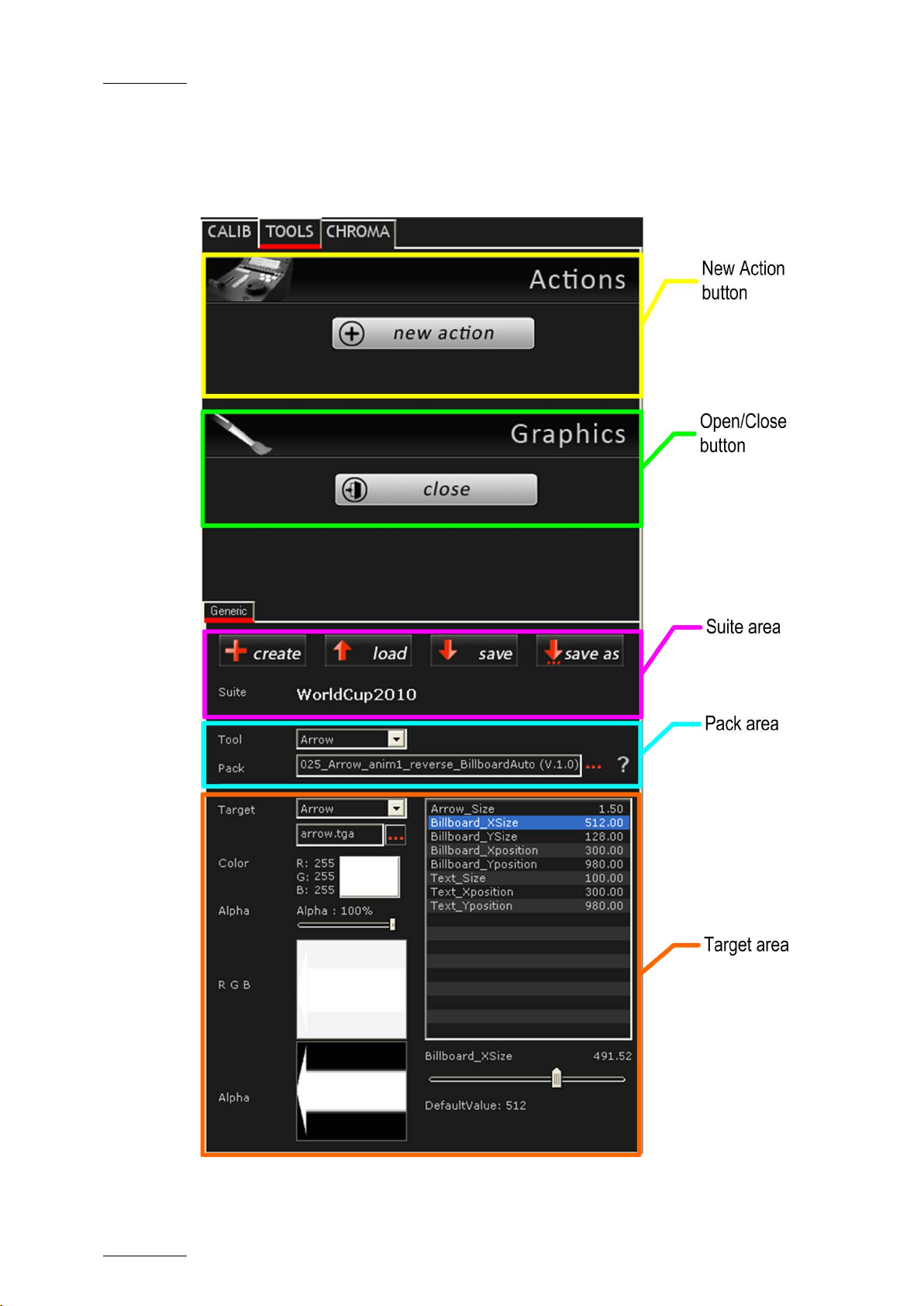
ACTIONS AREA
The following table de scribes the user interfa ce elements in the Actions area:
Button Description
New Action Not applicable.
The fields in this area aim at creating the offside line
animations. As Epsio is used in combin
LSM Remote Panel, the
created on the Remote Panel.
GRAPHICS AREA
You will define your graphic suite in the Graphics area. The Graphics area is a
tabbed zone that you can display or hide. Once you have defined and loaded your
graphic suite, it is recommended to close the Graphics area since you should not
need to modify the gr aphic suite in the course of the even t.
The Edit butto n shows the tabbed z one in the
Graphics area.
When this zone is open, the Edit button
becomes a Close button that allows the user
to hide the tabbed z one.
GENERIC TAB
The Generic Tab is the sub-tab in the Tools tab where you define your graphic
suite. It contains severa l areas, named as follows:
• Suite Area
• Pack Area
• Target Area
SUITE AREA
The Suite area contains the various commands you will use to manage your
graphic suite:
Field/Button Description
Button
file) from scratch.
Button to select and load
you will use in Epsio.
load a graphic suite to be able to
various graphic tools in Epsio.
Page 60

Issue 1.63.C
Epsio Version 1.63 – User’s Manual
EVS Broadcast Equipment – May 2011
54
currently open graphic
the graphic pack
commands on the Remote
Field/Button Description
Button to save the
suite.
Button to save the currently open graphic
suite under a new name .
Name of the loaded sui te
PACK AREA
The Pack area allows you to select the graphic packs that you want to work with
for each graphic tool. If request ed, the selected graphic pack can be further edited
in the Target area.
Field/Button Description
The Tool field allows you to select the graphic
tool you want to defi ne a graphic pack for.
The Pack field displays
assigned to the tool.
The ellipsis icon next to the Pack field
enables you to select the graphic pack you
want to work with.
The interrogation mark next t o the ellipsis
icon gives you access to a PDF document
that includes:
• a static preview o f the animation,
• the modifiable parameters,
• the associated
Panel.
TARGET AREA
In the Target area, you can refine the definition of the various components
included in the graphic pack you have selected in the Pack area. The components
of a graphic pack are called ‘t argets’.
This step is optional since you can decide to keep all predefined values of the
selected graphic pack. The parameters you can customize will depend on the type
of target you are edi ting:
Page 61

Epsio Version 1.63 – User’s Manual
EVS Broadcast Equipment – May 2011
Issue 1.63.C
55
The Alpha field allows defining the
whereas the black level of the chroma key
the result of the alpha channel
Field/Button Description
Drop-down field to s elect the type of target you
want to edit in the s elected graphic pack.
Field to select the template ima ge you will use.
Note
The template image needs to be in
TGA 32-bit
format.
Main Parameters
The main parameters associated to the loaded target are displayed on the left.
These parameters are described in the table below.
Field/Button Description
Specifies the color o f the selected component.
Click the color frame to open the color palette,
and select the reques ted color.
Slider that allows defining the transparency of
the Alpha layer of the sel ected component.
transparency for individual components,
allows defining the general transparency for
the offside line animation.
Displays the result of the color selecti on (RGB)
for the loaded target .
Displays
selection for the loaded target.
Drop-down field to select the font to be used
for the text to be d isplayed.
Page 62

Issue 1.63.C
Epsio Version 1.63 – User’s Manual
EVS Broadcast Equipment – May 2011
56
Note
The fonts need to be copied to the C:\WINDOWS\Fonts directory for
them to be available in Epsio.
They are not saved in the graphic pack itself. They consequently
need to be available on any Epsio workstation where the graphic
pack using the specific f ont will be installed.
Specific Par ameters
Other more specific parameters associated to the loaded target are displa yed in a
table on the right:
You cannot mod ify the values directly in the table.
You can however click or double-click the values in the table, which displays
respectively a sl ider or a dialog box to enable you to modi fy the value.
For more information, refer to the section 2.5.4 ‘How to Customize a Graphic
Suite’, on page 57.
2.5.3 HOW TO CREATE A GRAPHIC SUITE
This procedure explains how to create a graphic suite to which you will associate
the predefined gr aphic packs you will need to create animations.
To create a graphic su ite, proceed as follows:
1. In the TOOLS tab, Graphics area in Epsio, click the Edit radio button in the
Tools working mode area:
The Generic tab is di splayed in the lower part of the Tools tab:
2. In the Graphi c area in Epsio, G eneric tab, click the button.
3. In the Save As window, type the name you wan t to give to your graphic suite in
the File Name field, and click Save.
This creates a graphic suite (.egs file) you will associate the graphic packs to.
4. In the Generic tab, click the arrow in the Tool drop-down field,
Page 63

Epsio Version 1.63 – User’s Manual
EVS Broadcast Equipment – May 2011
Issue 1.63.C
57
and select the tool t o be included in your graphi c suite.
5. In the Generic tab, click the ellipsis icon on the right of the Pack field,
and select the defaul t graphic pack (.egp file) you want to use.
A static preview of t he animation, with the related parameters and ass ociated
commands on the various graphic packs are availa ble as you click the
icon.
6. Repeat the steps 4 and 5 for each available tool.
7. Click the Save button to save the changes in the graphic suite you have
created.
The suite whose name is displayed at the top of the Generic tab is the loaded
graphic suite, in other words the suite that will be taken into account as you
create animations in E psio.
If you want to customize the graphic packs of your graphic suite, refer to the
section 2.5.4 ‘How to Customize a Graphic Suite’, on page 57.
2.5.4 HOW TO CUSTOMIZE A GRAPHIC SUITE
INTRODUCTION
Once you have created your graphic suite by assigning predefined graphic packs
(as described i n section 2.5.3), y ou can customize your graphic packs as follows:
1. In the TOOLS tab, Generic tab, and Graphic area, click the Load button and
select the graphic su ite you want to edit.
The selected graphic s uite is loaded.
2. If you want to save y our customized graphic suite under a new name, the Save
As button and assi gn a name to the customized graphic suite.
Otherwise, the changes will be saved in the loaded graphic suite.
3. In the Tool area, select the tool you want to edit the target parameters for from
the Tool drop-down field:
4. In the Target area, sel ect the target you want to customize in the Target drop-
down field:
,
The parameters associat ed to the loaded target ar e displayed below the
Target field, or i n the table on the right .
Page 64

Issue 1.63.C
Epsio Version 1.63 – User’s Manual
EVS Broadcast Equipment – May 2011
58
again the
5. To edit one of the main parameters displayed on the left of the table, you can
directly edit the field values:
o For a color selection, clic k the colored square and speci fy the RGB values.
o For a slider, move the slider to the left or right to respectively decrease or
increase the parameter value.
o For ot her fields, proceed as usu al.
o Click the Save button regularl y to save your changes.
6. To edit one of the parameters displayed in the table, proceed in one of the
following ways:
o To mod ify the value using a sl ider, click once the reques ted parameter.
This displays a slider below the table:
Move the slid er to the requested value. The value is autom atically modified in
the table. See al so the note below.
o To directly type the requested value in a field, double-click the requested
parameter:
This opens a dialog bo x similar to the followin g one:
Click in the field, t ype the requested parame ter value and click OK.
7. Click the Save button to save the changes in the graphic suite.
Note on sliders
The displayed slider range corresponds to a portion of the full available
range, and depends on the selected va lue.
If the requested value is not available in the slider range, move to the
nearest value available, select another field, then select
requested field. The slider range will be adapted and will include the
requested value.
Page 65

Epsio Version 1.63 – User’s Manual
EVS Broadcast Equipment – May 2011
Issue 1.63.C
59
effect at the beginning of the
2.6 DEFINING THE REPLAY SETTINGS
INTRODUCTION
The Replay settings are applied by default when you play back the offside line
animation once it has been created.
HOW TO MODIFY THE REPLAY SETTINGS
You can modify the Replay settings as fol lows:
1. From the main menu, pre ss SHIFT+D (EPSIO) to enter the Epsio menu.
2. From the o ffside line mode, press SHIFT+MENU to display the Replay settings
screen:
Replay Settings p. 1.1 [F1] Pause Duration: 019 Frame(s) [F2] Fade In Duration: 015 Frame(s) [F3] Fade Out Duration: 015 Frame(s) [F4] Preroll Duration: 02 Second(s) [F5] Default playback speed : 100% [F6] Clear All Events
[Menu] Quit [F0] Next
3. Select the function k ey related to the setting you want to modify.
4. Jog the wheel to set the requested value.
5. Press MENU to l eave the Replay settings screen.
REPLAY SETTINGS
The following table ex plains briefly the replay settings:
Setting Description
Pause Duration Duration o f the pause before displa ying the animation.
The pause duration can be between 0 and 300 frames. It
is recommended to have a minimum value of 3 frames.
Fade In Duration Duration of the fade
animation.
The fade in durat ion can be between 0 and 300 frames.
Fade Out Duration Duration of the fade effect at the end of the animation.
The fade out duration can be between 0 and 300 frames.
Preroll Duration Number of seconds where the clip is paused before the
Page 66

Issue 1.63.C
Epsio Version 1.63 – User’s Manual
EVS Broadcast Equipment – May 2011
60
animation when the user presses the Last Cue button.
during the animation
Setting Description
The Preroll value can be between 1 and 60 seconds.
Default Playback
Speed
Default playback speed applied
when the user presses th e PLAY button.
The default playback duration can be between 0 and
300%.
Clear All Events Clears all the offside animations that have been saved
under the F1 to F10 function keys.
Page 67

Epsio Version 1.63 – User’s Manual
EVS Broadcast Equipment – May 2011
Issue 1.63.C
61
Offside
Arrow
Circle
Graphics
ChromaK
OSD
Graph
<-- Calib
Calib -->
3. Creating Graphic
Animations
3.1 GENERAL INFORMATION
3.1.1 PREREQUISITES
Before you can create and play back an offside lin e or live animation in Epsio, you
must have performed the follow ing configuration steps, which are described in the
Configuration chapter:
• Calibrating th e cameras
• Configuring th e chroma key and selecting a chroma key profile
• Creating, cust omizing and loading the req uested graphic suite
• Defining the repl ay settings
3.1.2 OVERVIEW ON THE EPSIO MENU
From the main operation al menu, press SHIFT+D to access the Epsio menu:
Page 68

Issue 1.63.C
Epsio Version 1.63 – User’s Manual
EVS Broadcast Equipment – May 2011
62
ChromaK
OSD
Graph
<-- Calib
Calib -->
Detect
in the
the live tools is active. If the automatic detection fails,
forces again the automatic detection
Offside
Arrow
Circle
Graphics
EPSIO MAIN MENU
The Epsio mai n menu contains the following com mands:
Command Description
Graph Allows the user to display or hide the Epsio animation that
has been created. The Graph command is active when you
enter the Epsio menu.
ChromaK Allows the user to enter the Chroma Key menu, in which you
can configure the chro ma key definition.
Refer to the section 2.4.2 ‘Accessing the Chrom a Key Menus’,
on page 40.
OSD Allows displaying or hiding the OSD information on the output
monitor. By default, the OSD in formation is displayed.
<-- Calib Allows moving to the previous calibration angle
Calibration tab of Epsio.
Calib--> Allows moving to the next calibration angle in the Calibration
tab of Epsio.
Detect The playfield limits are automatically detected when one of
pressing Detect
mechanism. This opt ion is only available wi th the live tools .
SECONDARY MENU
The secondary menu cont ains the various tools you can use in Epsio.
To access or leave the secondary menu, press the MENU key on the Remote
Panel.
To activate a tool in the secondary menu, click the key corresponding to the
requested tool: Offside (A), Ar row (B), Circle (C), Graphics (D ).
Page 69

Epsio Version 1.63 – User’s Manual
EVS Broadcast Equipment – May 2011
Issue 1.63.C
63
Offside
Arrow
Circle
Graphics
ChromaK
OSD
Graph
<-- Calib
Calib -->
3.2 CREATING AN OFFSIDE ANIMATION
3.2.1 REMOTE MENU WITH OFFSIDE FEATURE ACTIVE
If you want to create an offside li ne, you need to do the following before you enter
the Epsio menu:
• Position on the f rame where you want to cr eate an offside line animati on.
From the main operation al menu, press SHIFT+D to enter the Epsio menu:
The Epsio menu is disp layed with the Offside t ool active.
If the Offside tool is not active , you can activate it as you activate a live tool (Se e
section 3.3.1 ‘How to Activate a Li ve Tool‘, on page 66.
The Graph feature is a ctive by default.
The Mark key i s blinking red on the LSM Remote Panel.
The virtual playfiel d is displayed on the op erator’s PGM.
Note
If the playfield limits are automatically detected, the virtual playfield
lines are red. Otherwise, the virtual playfield lines will be white. In this
case, you firs t need to validate the pl ayfield limits manually.
3.2.2 HOW TO VALIDATE THE PLAYFIELD LIMITS
INTRODUCTION
Based on the calibration performed, the playfield limits are automatically detected
and matched to the virtual playfield when you enter the offside line mode. In this
case, the virtual pla yfield lines are displa yed in red.
If the image on which you want to create your offside line is slightly blurred, or
does not display enough lines on the playfield for the automatic detection to work
properly, the virtual playfield will be made of white lines.
If the auto-detection of the playfield does not work (white lines) or if the virtual
playfield lines are not perfectly matched to the real playfield, you first have to
validate the playfield limits. This action consists of repositioning the virtual
playfield limits onto the real playf ield limits.
Page 70

Issue 1.63.C
Epsio Version 1.63 – User’s Manual
EVS Broadcast Equipment – May 2011
64
Rst Cam
Local
Sync Prv
EPSIO
Cam A
Cam B
ChromaK
OSD
GRAPH
PROCEDURE
To validate the playf ield limits, proceed as follows:
1. When you have entered the offside line mode, right-click one of the points on
the virtual field. This can be a virtual point you have added during the
calibration.
2. Drag the virtual fiel d to match the real playfi eld.
3. Release the mouse.
4. Use the mouse wheel to adjust the zoom.
The real playfield limits have been validated, and the virtual playfield lines are
now displayed in red o n the monitor.
3.2.3 HOW TO CREATE AN OFFSIDE LINE ANIMATION
To create an offside line animation, proceed as follows:
1. In the operational menu, click A, B, C or D to select the c amera that you want
to use to create the offside line animation:
2. Pause on the offside frame.
3. Press SHIFT+D to access the Epsi o menu.
The GRAPH featur e is automatically active (black background).
4. Looking at the operator’s PGM, position the offside line using the mouse or the
jog.
5. Press MARK. This has the follow ing effects:
o The vi rtual playfield is re moved on the operator’s PGM.
o A snap is created on the director’s preview.
6. If you want to adjust the position of the offsi de line, press CLEAR.
The nowline returns to the positio n on the record train t hat was selected when
you entered the Epsio menu in step 3.
Repeat step 5 to mark a new position for the beginning of the offside line
animation.
7. Go back to a position before the TC where you have marked the start of the
offside sequence:
o Press Last Cue to go ba ck to the predefined pr e-roll
o Jog t o the requested position
8. To play the offside line sequence back with the offside line animation, do one
of the following:
o Press PLAY to play back at the predefined pl ayback speed.
o Use th e lever.
Page 71

Epsio Version 1.63 – User’s Manual
EVS Broadcast Equipment – May 2011
Issue 1.63.C
65
The director’s PGM and the operator’s PGM are ru nning and pause when it
gets to the beginning of the offside line animation. The pause duration
depends on the Pause Dur ation setting. T he animation is then played.
9. After the animation has been played, you can use the lever or press PLAY to
carry on playing the r ecord train.
10. Press RECORD to go out of the E psio menu.
If the operator keeps the Graph command active, the graphic will be played when
the clip will go on a ir.
If the director invalidates the offside line on his PGM, the operator can press A
again to deactivate the Graph command. When the clip will go on air, the offside
sequence will be playe d out ‘clean’, without the of fside line animation.
3.2.4 SAVING POSITION S OF OFFSIDE LINE ANIMATIONS
You can save the position of maximum ten offside line animations using the
function keys F1 to F1 0.
HOW TO SAVE THE POSITION OF AN OFFSIDE LINE
When you have marked your offside line using the MARK key, you can save its
position by pr essing the F_ keys on the Remote Panel.
HOW TO RECALL THE POSITION OF AN OFFSIDE LINE
To recall the offside line position you have previously saved und er a function key,
you first nee d to enter the Epsio menu a nd activate the off side line mode.
Recall the position by pressing the F_ key corresponding to the saved position of
the requested offside line.
Once you have recalled the position, you can press MARK to redefine the offside
line animation at the position you have recal led.
Page 72

Issue 1.63.C
Epsio Version 1.63 – User’s Manual
EVS Broadcast Equipment – May 2011
66
Offside
Arrow
Circle
Graphics
ChromaK
OSD
Graph
<-- Calib
Calib -->
Detect
3.3 CREATING A LIVE ANIMATION
3.3.1 HOW TO ACTIVATE A LIVE TOOL
To activate a live to ol in the Epsio menu, you nee d to do the following:
1. Press MENU to enter the second ary menu.
2. Select the key corresp onding to the requested liv e tool:
The secondary menu clos es automatically.
The selected live tool is displayed on a black background, and the Detect
command is disp layed in the main menu.
3.3.2 HOW TO CREATE AN ARROW OR CIRCLE ANIMATION
When you are in the Ep sio main menu, and have selected t he live tool you want to
use, proceed as follow s to create a live animat ion:
1. Looking at the operator’s PGM, press D (Detect) to refresh the automatic field
detection based on th e live feed.
The virtual playfiel d is matched to the real pl ayfield.
2. Position the mouse pointer where you want the arrow to start or the center of
the circle to be disp layed.
The live animation is applied to the current t imecode of the video material.
3. You can then perform o ne of the following action s:
o Clic k again on the field with t he mouse to reposition the animation.
o Press Mark to remove the virtual playfiel d in red wireframe.
o Press A (Graph) to hi de the animation ( if requested).
o Press the TAKE key to toggle between the arrow and the ci rcle animation.
3.3.3 USING THE GRAPHICS TOOL IN EPSIO
As soon as the Graphics live tool is activated in the secondary menu, the graphic
defined in the graphic suite will be displayed continuously as soon as the user
comes back to the Epsio main menu, and as long as the Graph command is active.
Page 73

EVS Broadcast Equipment
Liège Science Park
16, rue Bois St Jean
B-4102 Ougrée
Belgium
Corporate
Headquarters
+32 4 361 7000
North & Latin America
Headquarters
+1 973 575 7811
To learn more about EVS go to www.evs.tv
Asia & Pacific
Headquarters
+852 2914 2501
Other regional offices
available on
www.evs.tv/contact
 Loading...