

Page 1
INSTR UCT IO N MANUAL (en)
Page 2

Welcome
This manual is designed to be a reference tool for the installation and operation of your system;
you can find information about the DVR features and functions, as well as, a detailed explanation
of the menu trees.
Before installation and operation please read the following safeguards and warnings carefully!
Import ant Safeguards and W arn ings
Do not place heavy objects on the DVR.
Do not let any liquids spill onto or i nto the DVR.
Please ensur e f ans and vent openings are not blocked and that the unit is placed in an area with
adequate air circulation.
Do not try to disassemble or replace components other than the installation of the hard disk
drive.
Environment
Please plac e and use th e DVR in an area t hat can m aintain a tem perature ran ge of 0°C to 40°C
(32°F to 104°F).
A void pl acing the DVR in direct sunlight and keep away from any heat source.
Do not install the DVR in a damp environment.
Do not use the DVR in a smoky or dusty environment.
Please ensure that the DVR is placed on a level and stable workplace.
Please install it in a well ventilated area and please keep all vents clean and clear.
Use only the AC adapter included with your DVR and within the voltage ratings noted on the
adapter.
Page 3

Directory
1 Production Introduction ............................................................................................................................ 1
1.1 Product overview ........................................................................................................................... 1
1.2 Main functions ............................................................................................................................... 1
2 Open-package check and cable connections .......................................................................................... 2
2.1 DVR package contents .................................................................................................................. 2
2.2 Hard disk installation ..................................................................................................................... 2
2.3 Front panel..................................................................................................................................... 3
2.4 Rear panel ..................................................................................................................................... 4
2.5 Port Connection Overview ............................................................................................................. 4
2.6 Audio and video input and output connections ............................................................................. 5
2.6.1 Video input connections ...................................................................................................... 5
2.6.2 Video output connections and options ................................................................................ 5
2.6.3 Audio signal input ................................................................................................................ 5
2.6.4 Audio signal output .............................................................................................................. 5
2.8 Speed dome connections .............................................................................................................. 6
3 Basic operation ........................................................................................................................................ 7
3.1 Preview .......................................................................................................................................... 7
3.2 System Login ................................................................................................................................. 8
3.3 Desktop shortcut menu ................................................................................................................. 8
3.3.1 Main menu ........................................................................................................................... 9
3.3.2 Record Mode ..................................................................................................................... 10
3.3.3 Search/Pl a yb ack ............................................................................................................... 10
3.3.4 PTZ control ........................................................................................................................ 14
3.3.5 Tour setup .......................................................................................................................... 20
3.5.6 Audio Adjust ....................................................................................................................... 21
3.3.7 Logout ................................................................................................................................ 21
3.3.8 Window switch
4 Main menu ............................................................................................................................................. 23
4.1 Main menu navigation ................................................................................................................. 23
4.2 Search/Playback .......................................................................................................................... 24
4.3 Record ......................................................................................................................................... 24
4.3.1 Record ............................................................................................................................... 24
4.3.2 Record Conf ...................................................................................................................... 25
4.3.3 Region Cover .................................................................................................................... 26
4.4 HDD Manage ............................................................................................................................... 27
4.5 System setup ............................................................................................................................... 28
4.5.1 Language .......................................................................................................................... 28
4.5.2 Date/Time .......................................................................................................................... 29
4.5.3 Account .............................................................................................................................. 30
4.5.4 GUI Display ....................................................................................................................... 34
4.5.5 Video ................................................................................................................................. 35
4.6 Advanced ..................................................................................................................................... 36
4.6.1 Alarm Set ........................................................................................................................... 36
4.6.1.1 Mail .......................................................................................................................... 37
................................................................................................................... 22
Page 4

4.6.1.2 Video Blind .............................................................................................................. 38
4.6.1.3 Alarm Management ................................................................................................. 39
4.6.2 Version............................................................................................................................... 39
4.6.3 Motion Detect .................................................................................................................... 40
4.6.5 Auto Maintain ..................................................................................................................... 42
4.6.6 PTZ Configure ................................................................................................................... 45
4.6.7 Network ............................................................................................................................. 46
5 FAQ and maintenance ........................................................................................................................... 51
5.1 FAQ .............................................................................................................................................. 51
5.2 Maintenance ................................................................................................................................ 55
Appendix 1. Remote control operation ..................................................................................................... 57
Appendix 2. Mouse operation ................................................................................................................... 58
Appendix 3.Hard disk capability calculation ............................................................................................. 59
Appendix 4. Technical Specifications ........................................................................................................ 60
Page 5

1 Production Introduction
1.1 Product overview
This series DVR is designed especially for security purposes which m akes it an outstanding digital
surveillance product. It introduces an embedded LINUX operating system which is more stable. It
introduces the standard H.264mp video compressed format and G.711A audio compressed format
which ensures the highest q uality imag e, low error coding r atio, and single f rame playing. It utilizes
TCP/IP network technology which achieves the strongest network communication and
telecommunication ability.
This DVR can be use d indiv idually or onl ine as part of your s afety surv eillanc e network and with the
included professional network video surveillance software, it can help you to maintain a strong
communication and telecom municati on network.
1.2 Ma in functions
Real-time surveillance
Analog interface and VGA interface (VGA interface is equipped selectively)
Surveillance function through monitor or display
Data Storage
User sel ected m otion activ ated hard dr ive “ sleep” and “wak e” functi ons to extend s torag e capacity a nd
extend life-span.
Special storage format which insures data safety.
Compression
Real-time compression by individual hard drive which insures the audio and video signal synchronization
and stability.
Backup
Through SATA and USB interface and also through Internet download.
Playback
Individual real-time video recording, as well as, search, playback, network surveillance, recording check,
and downloading.
- 1 -
Page 6

Multi-playback mode.
Internet operating
Internet surveillance in the real time
PTZ control
Recording check and real-time playback
Communication interface
RS485 interface for PTZ control
Standard Ethernet network interface with RJ45 jack
intelligent operations
USB Mouse and backup/copy/paste functions
2 Open-package check and cable connections
2.1 DVR package contents
Please verify that there is not visible damage to the DVR and then verify the following:
• 4 channel H.264 DVR
• AC Power Supply
• Remote Control (requires 2 AAA batteries – not included)
• USB Optical Mouse
• (4) Screws to Mount HDD
• Inst allation CD
• User Manual
• Quick Guide
2.2 Hard disk installation
Install SATA hard disk drives before completing the initial software setup. (The below images are just
used to show how to install hard disk. The DVR in the photos is not the DVR in the package.)
- 2 -
Page 7

1. Remove case screws 2. Remove cover. 3. Install SATA hard drive
4.Connect SATA data cables 5. Install SATA power cables 6. Replace cover
7. Replace screws
2.3 Front panel
(1) IR remote receiver (2) Power indicator light (3) Previous file/1 (4) HDD indicator light
(5) Next file /2 (6) PTZ /8 (7) Slow play /3 (8) HDD Info/9
(9) Fast play/4 (10) Backward pause/5 (11) Record /0 (12) Play Pause /6
(13) Function switch (14) Search video/7 (15) USB (16) ESC
(17)Left (18) Up (19)Down (20) Menu/Enter (21) Right
- 3 -
Page 8
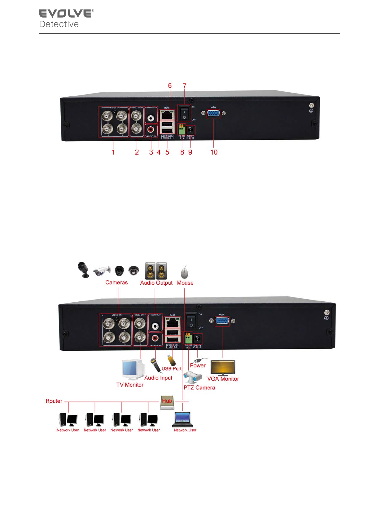
2.4 Rear panel
(1) Video input (2) BNC output (3) audio input (4) audio output (5) USB/Mouse*
(6) Network (7) Power Switch (8) RS485 (9) Power supply (10) VGA output
*NOTE* if the rear USB mouse port is used then the front USB port becomes non-functional.
2.5 Port Connection Overview
Picture 2.1 Connection Diagram
- 4 -
Page 9

2.6 Audio and video input and output connections
2.6.1 Video input connections
The video input ports utilize a BNC connector plug with an input signal of NTSC BNC (1.0V
, 75Ω).
P-P
The video lines should b e firmly connected to avoid sig nal interference and possible oxidation at t he
connection.
2.6.2 Video output c onnections and optio ns
The video output is divided into NTSC BNC (1.0V
, 75Ω) and VGA (selective configuration).
P-P
Please note the following regarding the display used for monitoring:
1. Do not leave the display on for long periods of time.
2. Stay away from any electromagnetic interference.
2.6.3 Audio signal input
Audio port is a BNC connector.
The audio signal line should be firmly connected to avoid signal interference and possible oxidation
at the connection.
2.6.4 Audio signal output
Normally the output parameter of DVR audio signal is greater than 200mv 1KΩ (BNC) which can be
connected to low impedance earphones, speakers, or other audio output equipments through a
pow er am plif ier. If the s peakers and micr ophone cannot b e isolated, feedback often occurs. The
following are some suggestions to help correct this issue:
1. Use a higher quality microphone.
2. Adjust the speaker volume to be under the threshold that produces the feedback.
3. Use materials that will absorb the sound and reduce reflection of the sound.
4. Adjust the layout of the speaker and microphone.
PTZ connect ions
2.7.
1. PTZ decoder connections
1. The grounding of a PTZ decoder and DVR must be shared otherwise the common-mode voltage
- 5 -
Page 10
could result in PTZ control failure - shielded twisted pair cable is recommended.
2. Avoid high voltage connections and use surge protectors.
3. When connecting use 120Ω resistance, paralleled, to ensure the signal quality .
4. The 485 AB lines of DVR cannot be connected with other 485 output equipment that is paralleled.
5. The voltage between the AB lines of the decoder must be less than 5V.
2. Front equipment grounding note
Incorrect grounding can result in damage to the unit.
3. PTZ input type unl imited
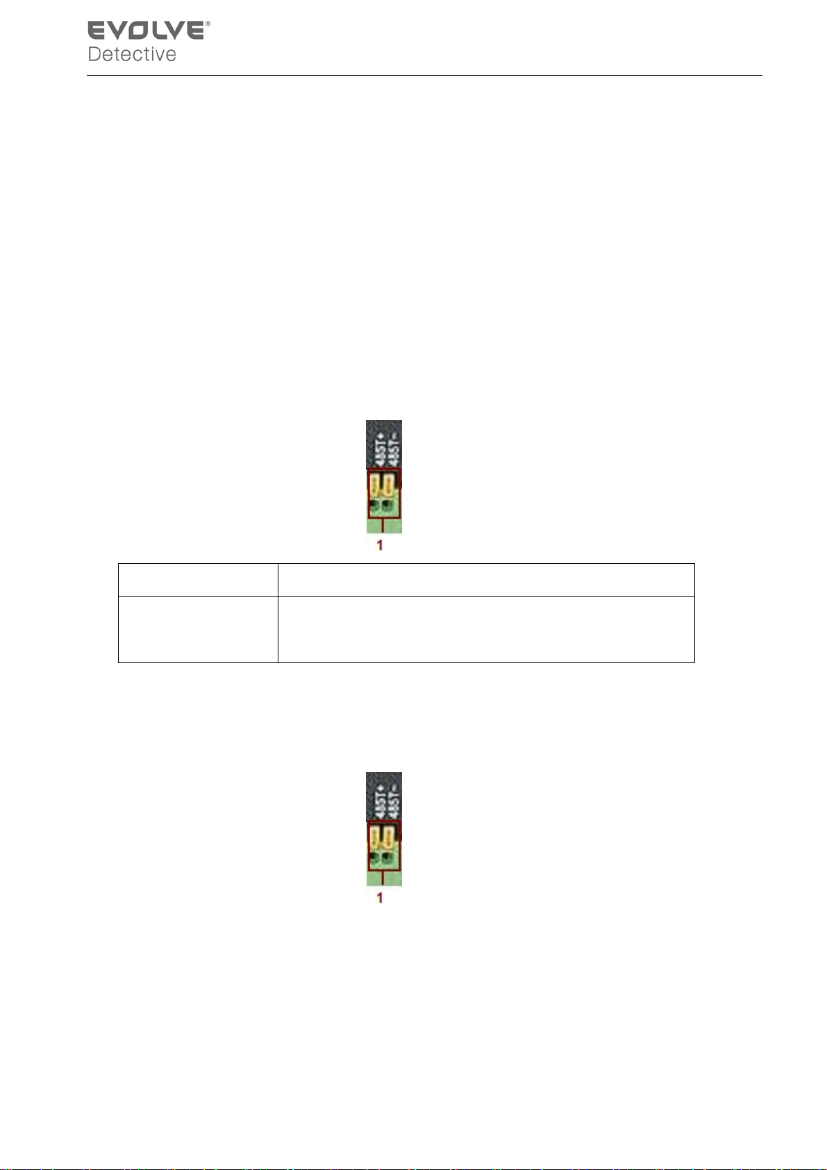
Parameter meaning
485T+/A,485T-/B 485communication interface which is connected with the
recording control equipments such as the decoder
2.8 Speed dome connections
1. Connect the 485 lines of the speed dome with the DVR 485 interface.
2. Connect the video line to the DVR video input.
3. Power on the speed dome.
- 6 -
Page 11
3 Basic opera ti on
Note: Any buttons that are displayed in gray indicates it is not supported.
3.1 Preview
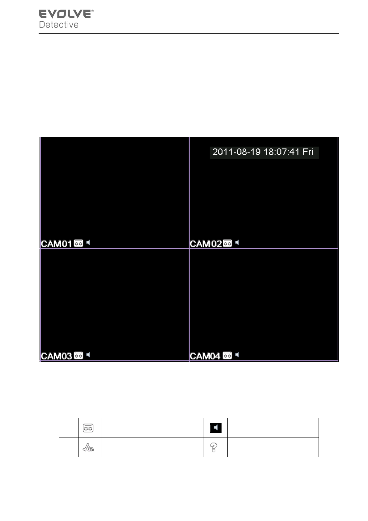
Picture3.1 16 Channel Preview
You can right click your mouse to switch between the windows.
The system date, time, channel nam e, survei llance v ideo, and the alarm status are s hown in each
window.
1
2
Recording status 3
Motion detect 4
Audio
Video loss
Table 3.1 Preview icon
- 7 -
Page 12
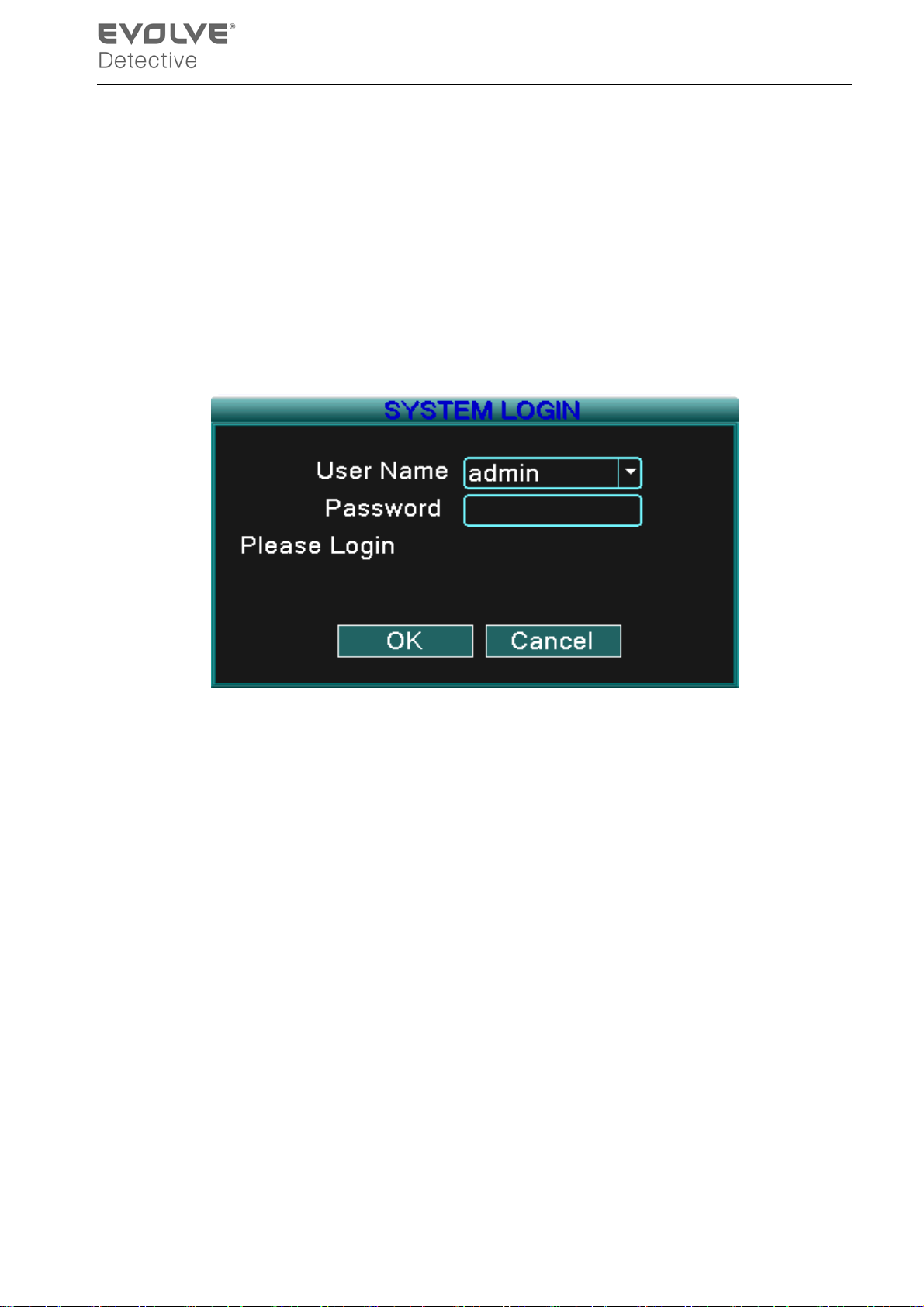
3.2 System Login
When the D VR boots up, the user m ust login and then the syst em will provide the corresponding
functions with that particular user’s authority level. There are three user settings: admin, guest and
default and these settings initially have no password assigned. Admin i s the adm inistrator l evel
while guest and default’s perm issi ons are “preview” and “v ideo pl ayback” only. User admin and
guest’s passw ord can be r evised, w hile their p ermissions c annot be r evised; user default is the
default login user whose permission can be revised but not its password.
Picture 3.2 System Login
Password prot ecti on: If th e passwor d is en tered in correct ly thr ee tim es, t he alarm wil l start. If
the password is entered incorrectly five times, the account will be locked.
(After 30 min utes or if the unit is rebooted, the account will be unlocked and you can try to
enter the password again).
For your system security, please modify your password after first login.
3.3 Desktop shortcut menu
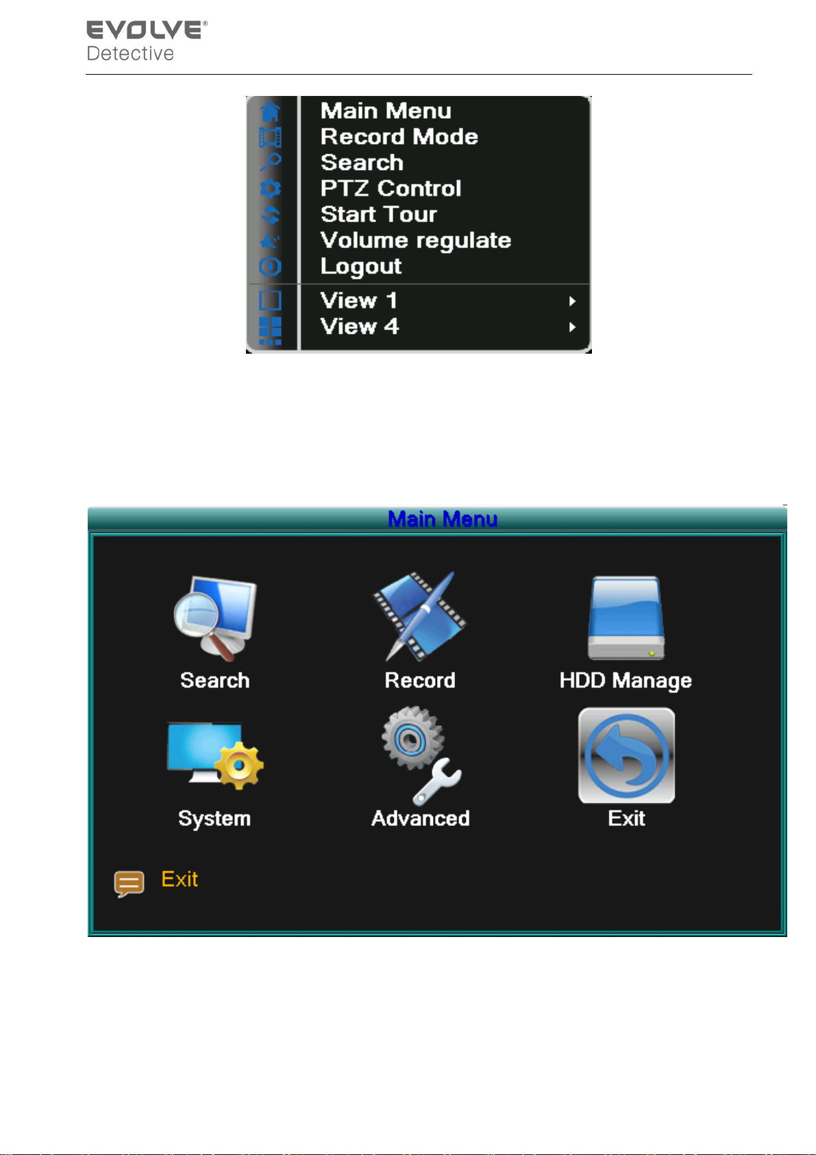
In preview mode you can right click your mouse to get a desktop shortcut menu. The menu includes:
main menu , record mode, Search, PTZ control, Start Tour, Volume regulate, Logout, view is
for 1/4/8/9/16 channel screens.
- 8 -
Page 13
3.3.1 Main menu
Picture 3.3 Shortcut Menu
When you login, the system main menu is shown as below.
Picture3.4 Main Menu
- 9 -
Page 14
3.3.2 Record Mode
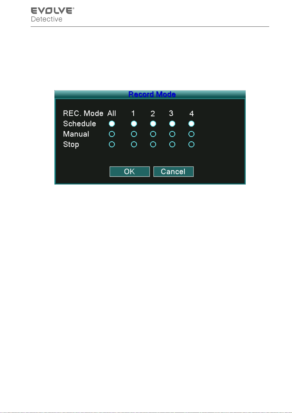
Please check current channel status: “○” means it is not in recording status, “●” means it is in
recordi ng stat us.
You can use the desktop shortcut menu or click [main menu]> [recording function]> [recording
set] to enter the r ecording control i nterfac e.
Picture 3.5 Record Mode
【Schedule】Record according to the configuration.
【Manual】Click the “All” button and all channels will record no mat ter which state the individual
channel is set to. Clicking the individual channels will allow only those particular channels
to record.
【Stop】Click the “Stop” button and all channels will stop recording no matter which state the
individual channels are set. Clicking the individual channels will stop the recording of that particular
channel.
3.3.3 Search/Playback
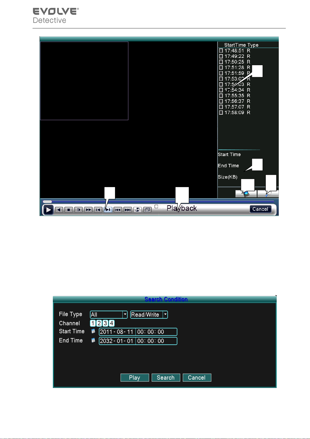
There are two methods for you to play the video files on the hard drive(s).
1. In the desktop shortcut menu - Main menu -> Search.
Note: The hard drive that saves the video files must be set as read-write or read-only state. (3.5.1)
- 10 -
Page 15
2
4
1
5 6
Picture 3.6 video playback
1. Listed files 2. File information 3. File searching
4. File backup 5. Operation hint 6. Playback control
【Listed files】Look up the listed files that are contained within that search criteria.
【File information】Look up the found file information.
【File searching】Search the file according to the searching parameter.
3
Picture 3.7 file searching
- 11 -
Page 16
File type: Set the searching file type.
HDD type: Set the searching HDD type.
Channel: Set the searching channel.
Start Time: Set the searching start time scan.
End Time: Set the searching end time scan.
【File backup】Backup the chosen file. Click the button and operate as directed.
Not e: The st orag e drive must be i nstalled bef ore th e file can be backed-up. If the backup is
terminated any files already backed-up can be played-back individually.
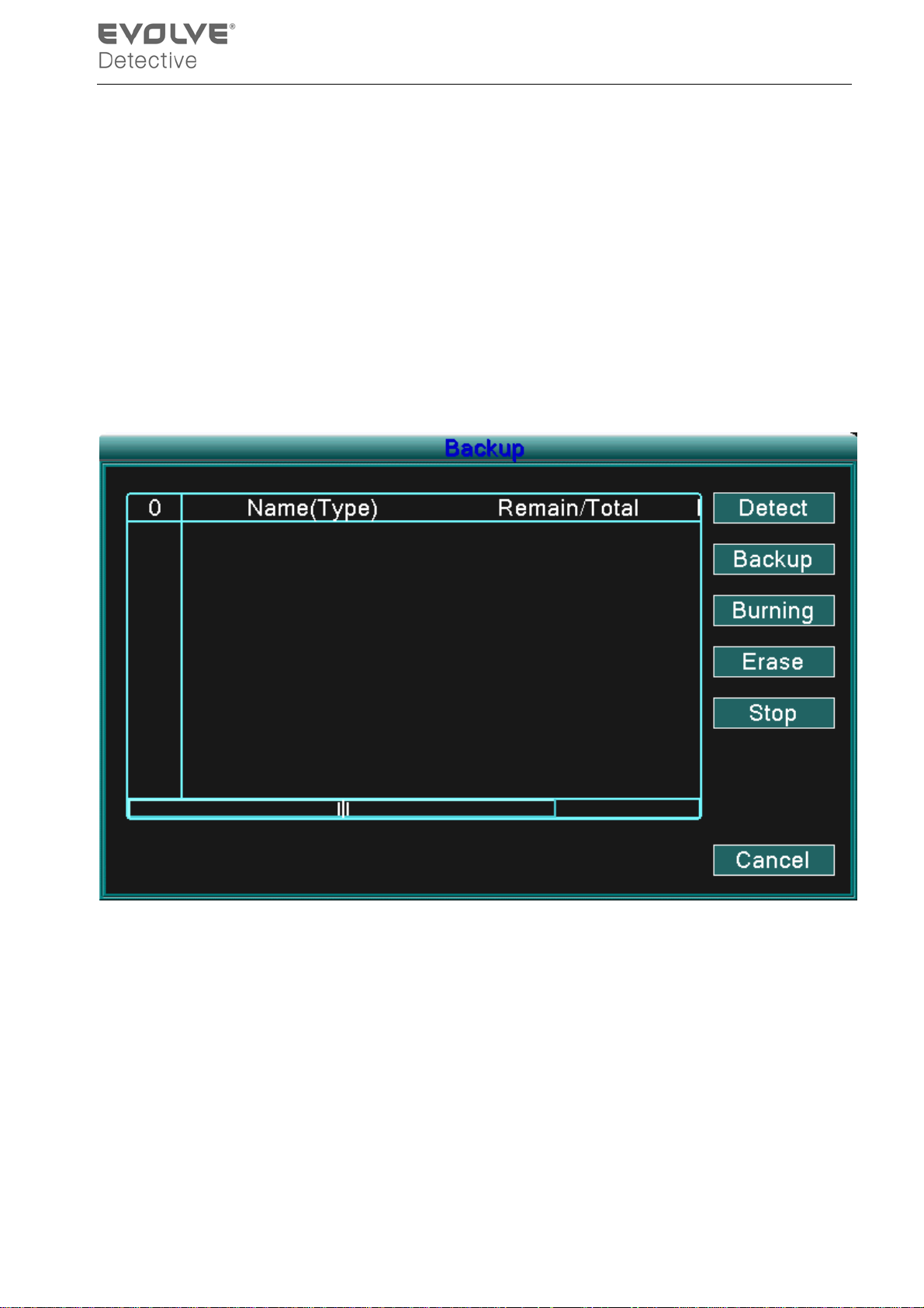
Picture 3.8 detect storage device
Detect: Detect the storage device connected to the DVR such as hard drive or USB drive.
Erasure: Choose the file to delete and click erase to delete the file.
Stop: Stop the backup.
Backup: Click backup button and a dialog box will open. You can choose the backup file
according to the type, channel and time.
- 12 -
Page 17
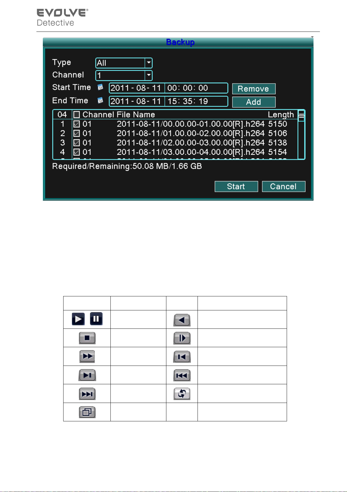
Picture 3.9 recording backup
Remove:Clear file information.
Add:Show file information meeting the set file attributes.
Start/Pause:Click the play button to start the backup and click the pause button to stop the
backup.
Cancel:During backup you can exit the page layout to carry out other functions.
【Playback control】Refer to the following sheet for more information.
Button Function Button Function
/
Play/pause
Stop
Fast play
Backward
Slow play
Previous frame
Next frame
Next file
Full screen
Table 3.2 Playback control key
Note: Frame by frame playback is only performed in the pause playback state.
- 13 -
Previous file
Circulation
Page 18
*Hint* You can display the function by placing the cursor on that area.
Special functions:
Accurate playback:Input time (h/m/s) in the time column and then click the play button. The
system will perf orm an ac c ur ate playback according to the search time entered.
Local zoom:When the syst em is in a single-window full-scr een p l aybac k mode, you c an dr ag y our
mouse onto the screen to select a section and then left click the mouse to activate the
local zoom. You can right click the mouse to exit.
3.3.4 PTZ control
Operation functions include: PTZ direction control, step, zoom, focus, iris, and setup operation,
patrol between spots, tr ai l pat r ol , b oundary scan, as s i stant switch, li ght switch, l evel rotation an d s o
on.
Note1. Decoder A (B) line connects with DVR A (B) line.
2. Click [main menu] > [system configuration] > [PTZ setup] to set the PTZ parameters.
3. The PTZ functions are decided by the PTZ protocols.
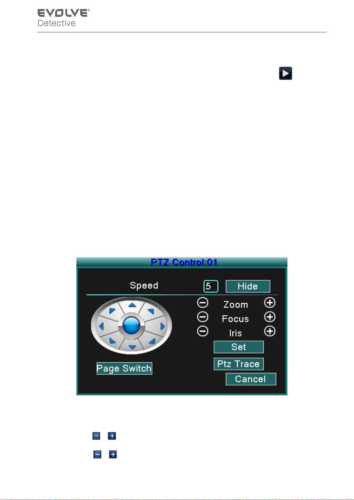
Picture 3.10 PTZ setup
【Speed】Set the PTZ rotation range. Default range: 1 ~ 8.
【Zoom】Click
【Focus】Click
/ button to adjust the zoom multiple of the camera.
/ button to adjust the focus of the camera .
- 14 -
Page 19
【Iris】Click / button to adjust the iris of the camera.
【Direction control】Control the PTZ rotation. 8 direction controls are supported (4 directions in Front
panel are supported)
【High sp eed PTZ】Full-scr een s how channel image. Left click your m ous e a nd you can control the
PTZ rotate orientation. Left click your mouse and then rotate the mouse to
adjust the multiple zoom options of your camera.
【Set】Enter the function operation menu.
【Page switch】Switch between different pages.
Special functions:
1. Preset
Set a location for the preset, call the preset point, and the PTZ will turn to the preset position.
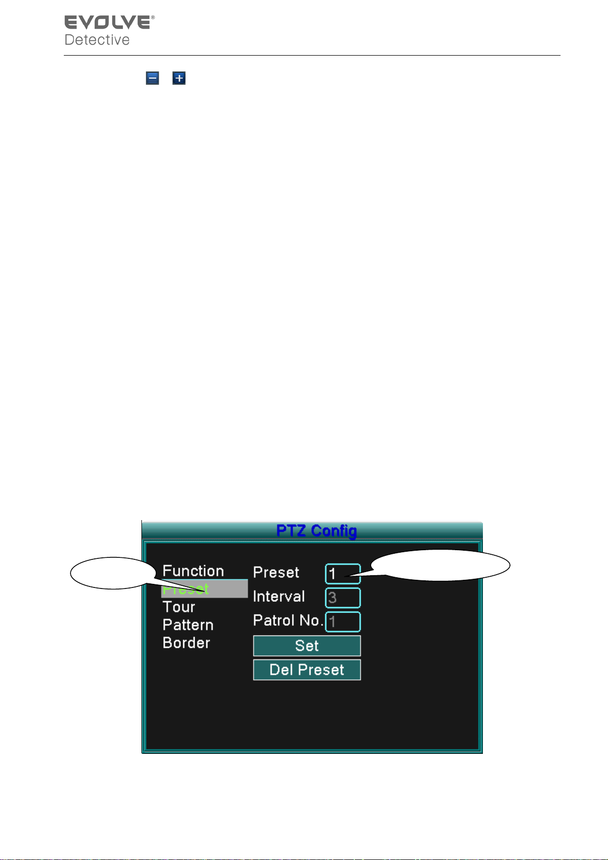
1)To set the Preset option:
Step1: As shown in Picture 3.10, click any of the Direction buttons and the PTZ w ill turn to that
position, click the Set button to enter that position as shown in Picture 3.11.
Step 2: click the Preset button, and then enter the preset points in the input blanks.
Step 3: click the Set butt on and the PTZ C ontrol w indow will open, shown in Picture 3.10, and this
completes the setup of preset points and preset positions.
To clear Preset:Input preset points, click Remove button to remove the preset.
Preset but ton
Preset point input bl ank
Picture 3.11 Preset Settings
- 15 -
Page 20
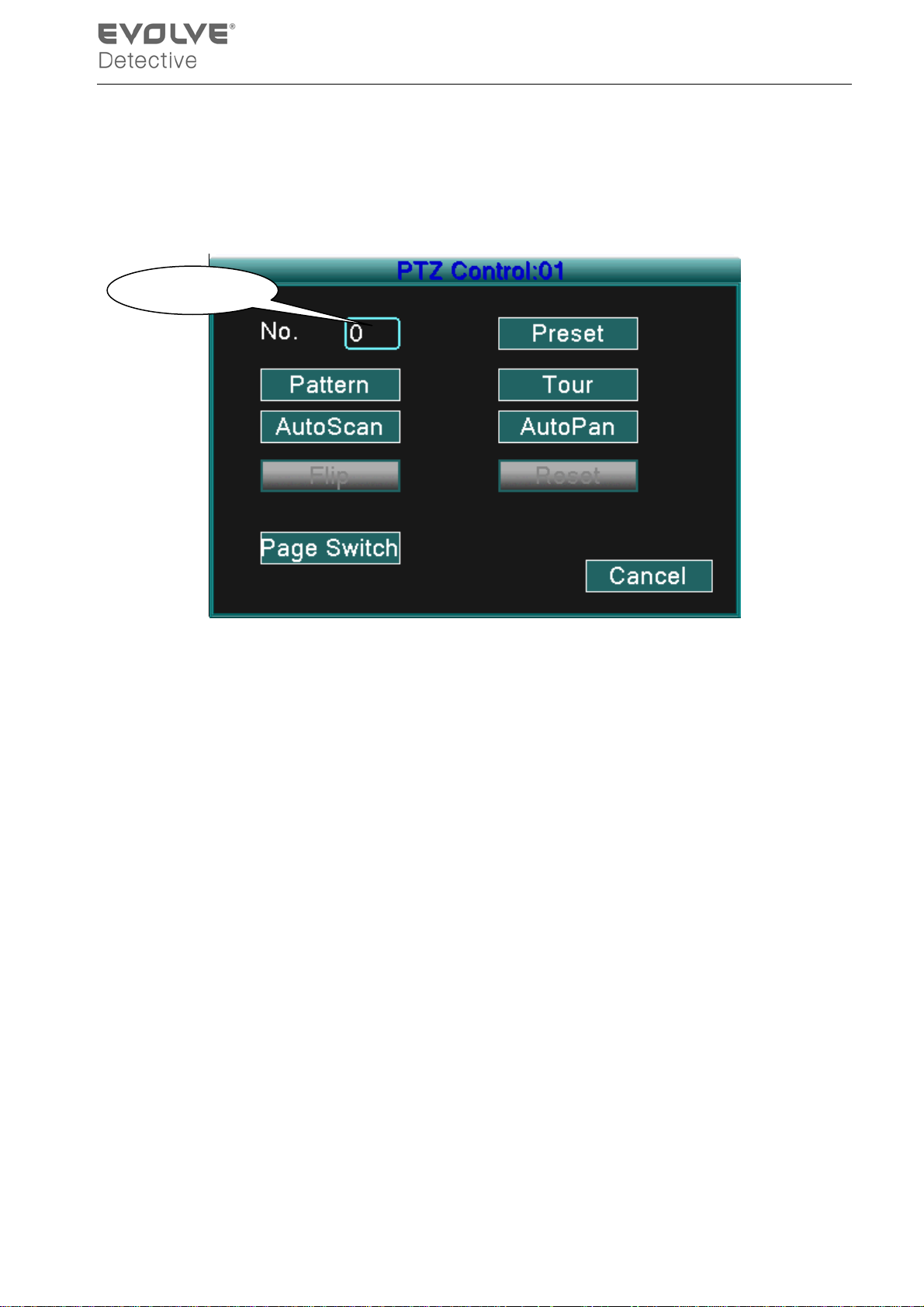
2)Preset Point Calls
Click the Page Switch button to enter the PTZ contr ol i nterf ace as show n in Pi ctur e 3.12. In t he
input b lank, enter the p res et poi nts and th en click the Preset b utton and the PTZ will turn to the
corresponding preset point.
Value input blank
Picture 3.12 PTZ Control
2. Touring between Points
1)Touring between Point Settings
Tour lines are connected by multiple preset points, to set the preset points:
Step1: as shown In Pict ure 3.10, t he Di rect ional keys w i ll tur n the PTZ to any desired location,
and then click the Set button to enter that location (Picture 3.13),
Step 2: click the Tour button, enter that value into the Tour Line and Preset Points blanks,then
click “Add P reset P oints” button to complete the settings (you can also add and del ete
Tour lines which have been previously set up)
Step 3: repeat steps1 and step 2, until all of the preset designated Tour points have been
entered.
Remove Preset:Input preset value in the blank, cli ck Remove Preset b utton to remove the
preset points.
Remove Tour Line:Input the number of the To ur l i ne, cl i ck D el Tour button to rem ove the Tour
line setting.
- 16 -
Page 21
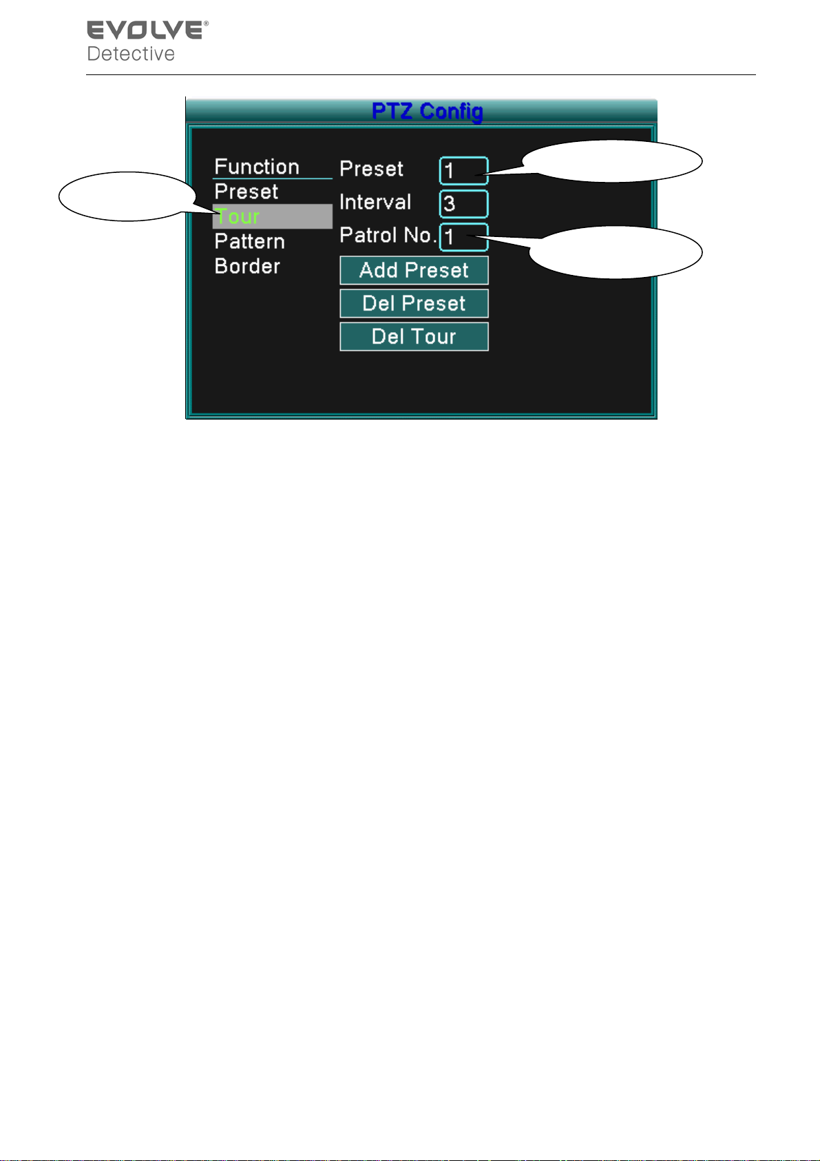
Cru i se Button
Preset Points Blank
Crui se Line Bl ank
Picture 3.13 Tour between Points Settings
2)Call-up Tour lines between Points
Click the Page Switch button (r efer to Pi cture 3.10) to enter the P TZ contr ol menu as shown in
Picture3.12. Input the number of the tour line in the value blank, then click “Tour between Points”
button, PTZ will begin to function according to the tour lines that are set. Click the Stop button to
stop touring.
2. Scan
The PTZ will work using the preset pattern line repeatedly.
1)Scan setup
Step1:As shown in Picture 3.10, click the Set button
Step2:Click Pattern button,as shown in Picture 3.14, input the scanning values in the Pattern
value blanks
Step3:Click Begin button and y ou c an set the following items: Zoom、Focus、 Aperture、
Direction and s o on (refer to Picture 3.10). Click Set b utton and you w ill be retur ned to the PZT
configure window, refer to Picture 3.14
Step4:Click End button to complete setup and then click the right mouse button to exit.
- 17 -
Page 22
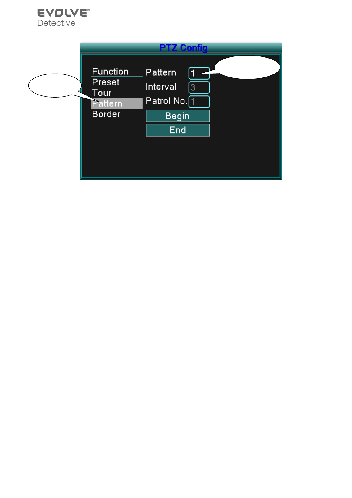
Scan B utton
Scan value blank
Picture 3.14 Pattern Setup
2)Pattern Calls
Referring to Picture 3.10, c lick Pag e Shift b utton, then enter PTZ control menu as shown i n
Picture 3.12. Inp ut the pattern number of the scan i nto the v alue blank, then c lick the Auto
Scan button,the PTZ will begin working using the Pattern lines. Click the Stop button to stop.
4. Boundary Scan
1)Boundary Pattern setup
Step1:Click the left Directional button to turn the PTZ to set a direction (refer to Picture 3.10)
and click the Set button, then select the Left Boundary button (refer to Picture 3.15)
Step2:Click the right Directional button to turn PTZ to set an opposite direction (refer to
Picture 3.1 0) a nd click the Set butt on, then select th e ri ght boundar y but ton (r ef er to
Picture 3.15)
Step3: The left and right boundary setup is completed.
- 18 -
Page 23
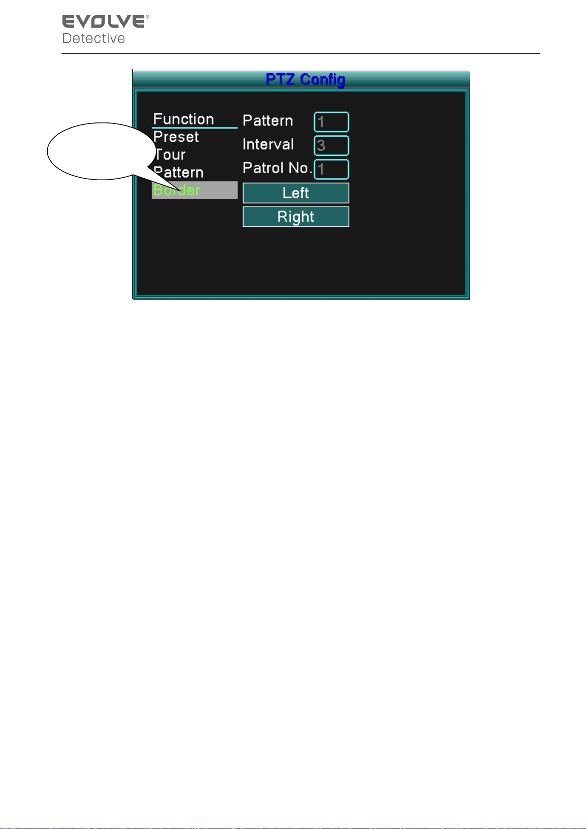
Line scan button
border
Picture 3.15 Boundary Scan Setup
2)Boundary Scan Calls
Click the Page Shift button (refer to Picture 3.10) to enter the PTZ control menu as shown in
Picture 3.12. Input the num ber of the Boundary scan in t he val ue blank and click the Auto
Scan button,the PTZ will begin working using the Boundary setup. Click the Stop button to
stop the scan.
5. Horizonta l Rotating
Click the Horizontal Rotating button and t he PTZ will rotate horiz ontally (rel ative to the or iginal
position of the camera). Click the Stop button to stop.
6. Rotate
Click on the horizontal Rotating button and the PTZ will turn around.
7. Reset
Click PTZ restart and all data clears to 0.
8. Page Switch
Click Page Switch button, (refer to Picture 3.10) and enter setting auxiliary function (refer to
Picture 3.16). The Auxiliary number corresponds to the auxiliary switch on the decoder.
- 19 -
Page 24
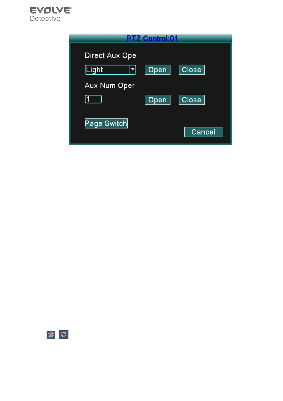
Picture 3.16 Auxiliary Function Control
【Direct Auxiliary Operation】Choose auxiliary equipment, select Open or Close button, or
switch control.
【Auxiliar y N um b er 】The op er ati on of the c or r es p ondi ng aux i l i ar y switch acc or di ng to the PTZ
agreement.
【Page Switch】 Click the Page Switch button and return to PTZ Main Menu (refer to Picture
3.10), the menu itself can be controlled by the menu control buttons
3.3.5 Tour setup
Set the patrol display. There are two methods for you to play the video files contained in the hard disk.
1. Using the desktop shortcut menu.
2. Main menu -> System setup->Video.
Yo u can choos e the si ngl e w indow, four w indow, nine w indow, or sixteen wi ndow patr ol display
for a single display.
【interval】Set the patrol switch interval. The set range is 5-120 seconds.
Note:
/ Means turn off/on the patrol.
- 20 -
Page 25
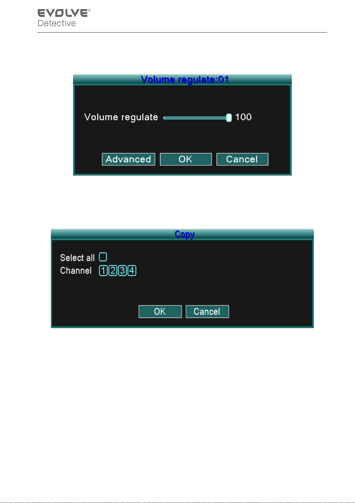
3.5.6 Audio Adjust
Adjust volume regulate parameters. You can use the desktop shortcut menu.
Picture 3.17 Audio Adjust
【Volume regulate】You can set the volume regulate value from 0 to 100.
【Advanced】Will allow volume control for each channel.
Picture 3.18 Audio matches Channel
You can match an y or all channels w hich you want to adjust, but only on e audio channel output is
valid at a time.
3.3.7 Logout
Logout by shutting down the s ystem or by rebooting. You can use the d esktop shor tcut to enter
[main menu].
- 21 -
Page 26
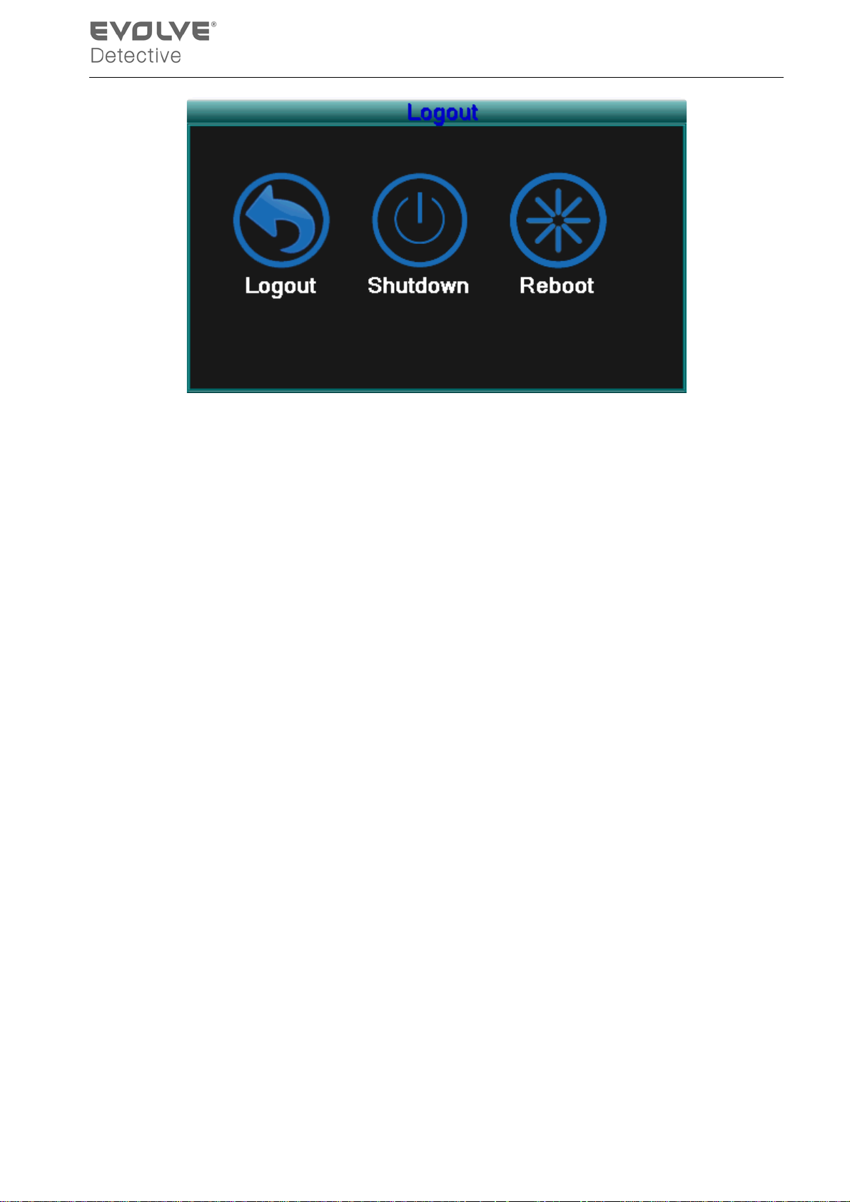
Picture 3.19 Logout/Reboot the system
【logout】Quit the menu. Requires password to logon.
【shutdown】Quit the system. Power Off the DVR.
【reboot】Quit the system. Reboot the system.
3.3.8 Window swi tch
Preview in a single window/four windows/eight windows/nine windows/sixteen windows according
to your choice.
- 22 -
Page 27
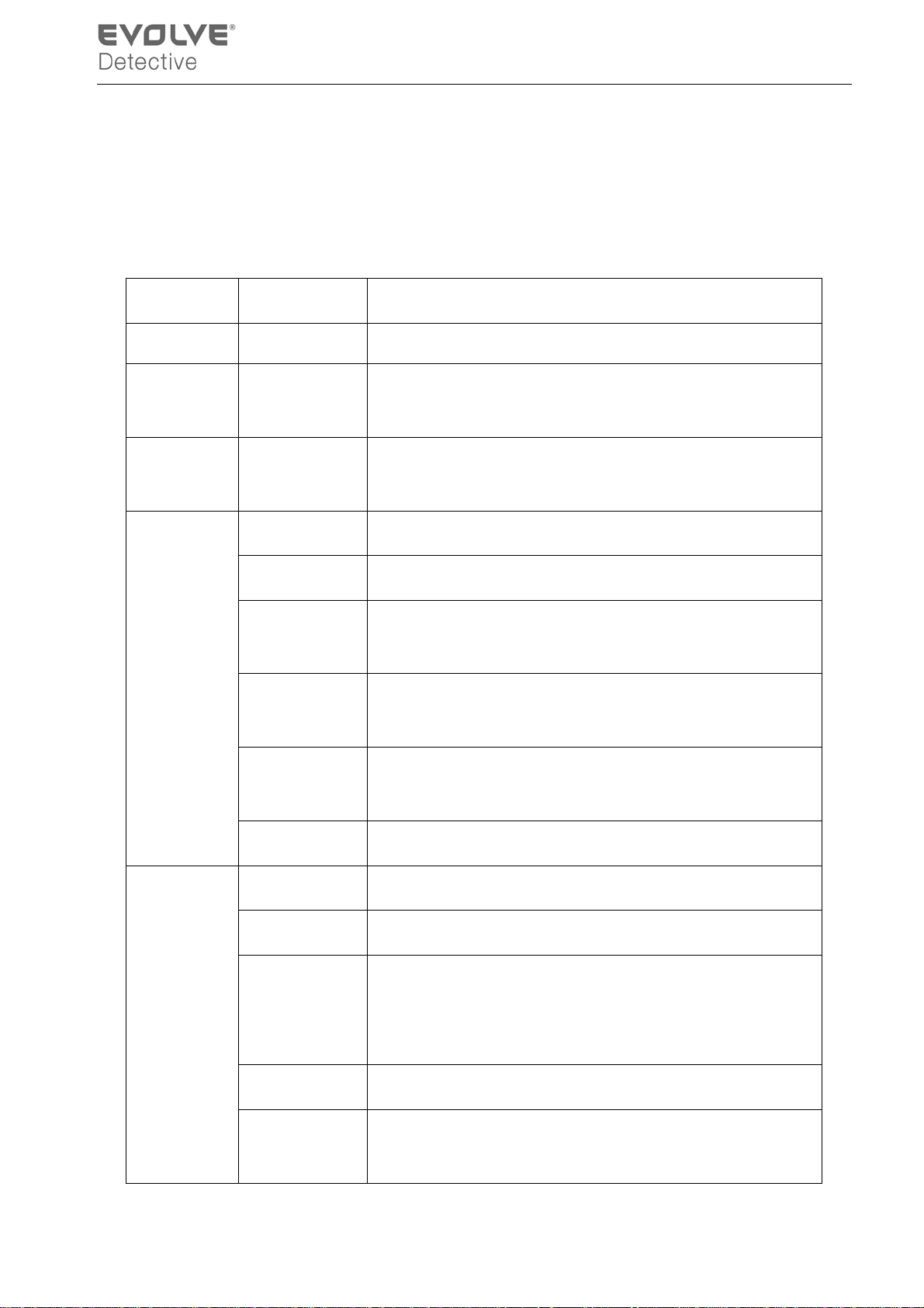
4.1 Main menu navigation
4 Main menu
Main menu
Search
Record
HDD
management
System
configuration
Sub menu
Language Set language.
Date/Time Set system time, data format and so on.
Account
management
GUI display
recording look-up, recording play, video file storage
Set the recording configuration, recording type, recording
time section
Set app oi nted hard di sk as r ead-w rit e dis c , r ea d-only disc or
redundant disc, clear data, resume date and so on
Modify user, team or password. Add user or team. Delete
user or team.
Set channel name, video time, color setting, preview tim e,
preview channel, record status, alarm status and so on.
Function
Advanced
Set resolution, video standard, tour time, and output adjust
Video
and so on.
Exit
Alarm Set
Version Info Display software version and build date.
Motion
detection
Mobile Monitor Mobile Monitor Setup.
Automatic
maintenance
Return last lever menu.
Send email or Show M essag e when alarm happening。
Set motion detect alarm channel, sensitivity, area, linkage
parameters: defending time section, scr een hint, recording,
PTZ, patrol
Set automatic reboot system , system upgrade, default
settings, log and so on.
- 23 -
Page 28
PTZ
configuration
Network
configuration
Exit
Exit Exit main menu and display Monitor.
4.2 Search/Playback
Refer to chapter 3.3.3.
4.3 Record
4.3.1 Record
Set channel, P TZ p r ot ocol , addr ess , b aud r at e, date bi t, s top
bit, and check.
Set basic network parameters, DHCP、 PPPOE、DDNS
parameter
Return last lever menu.
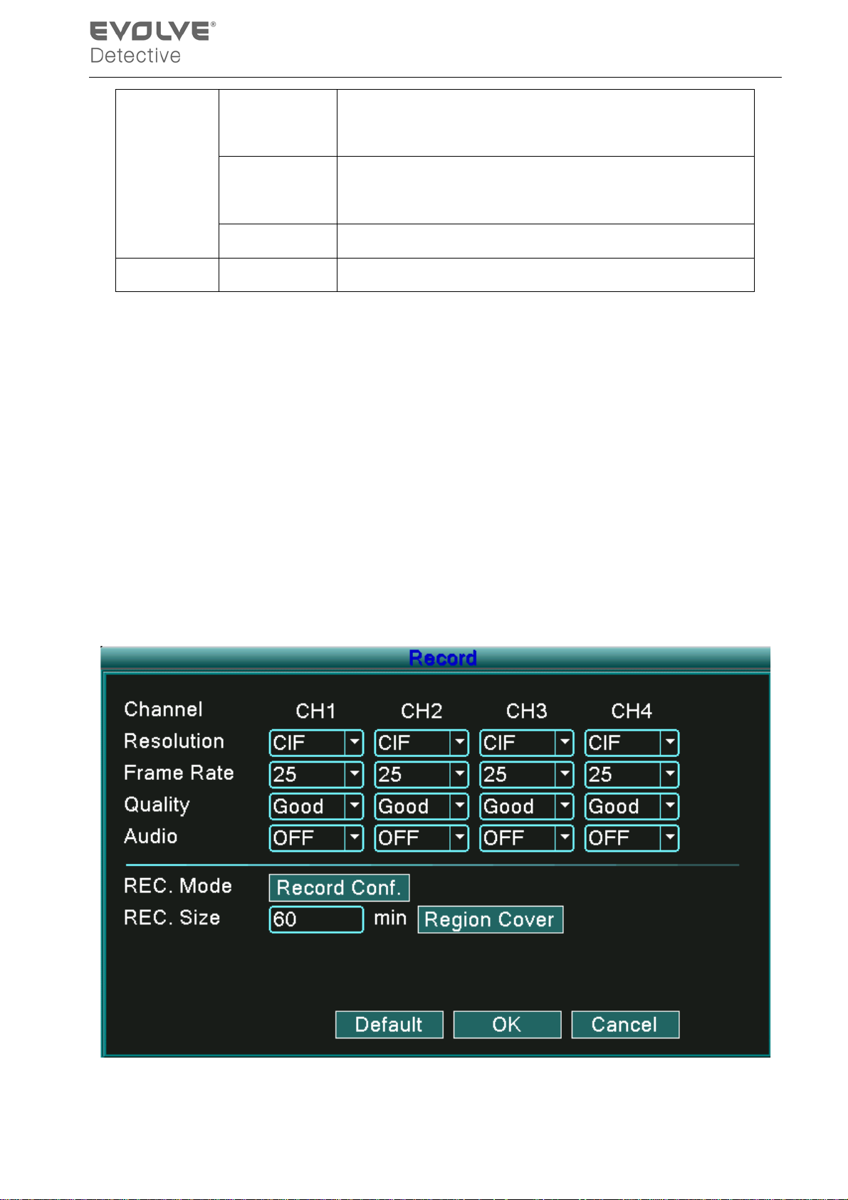
Set the recording parameters in the surveillance channel. The system is set to 24 hours consecutive
recording with the initial startup. You can modify by entering: [main menu]> [record]> [record] to set.
Note:There must be at least one read-write hard disk installed for this to function.(refer to chapter 4.4)
Picture 4.1 Record
- 24 -
Page 29
【Channel】Choose the corresponding channel number to set the channel. Choose the All option to
set every channel.
【Resolution】Set the resolution (D1 /HD1/CIF/QCIF) for each channel file. CIF is default value.
【Frame Rate】Set the frame rate of each channel. 25 is default value (0 to 30 for NTSC).
【Quality】Set the quality of each video channel. Good is default value (worst, worse, general, good,
better, or best).
【Audio】Set the audio status of each channel. ON is default value.
【REC. Size】Set the time length of each video file. 60 minutes is default value (1 to 120 min).
【REC Mode】Refer to chapter 4.3.2.
【Region Cover】Refer to chapter 4.3.3.
Note:Pressing the “Default” button, will replace all configured settings to default settings.
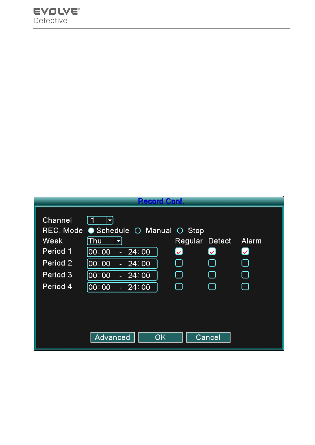
4.3.2 Record Conf
Picture 4.2 Record Conf
【Channel】Choose the corres p ondi ng c han nel n umber to s et the c ha nnel . C ho os e the all opt i on t o s et
the entire channels.
【REC. Mode】Set video state: Schedule, Manual and Stop.
Schedule: Record according to the set video type (common, detection, or alarm) and time section.
- 25 -
Page 30
Manual: Click the manual butt on and the corresponding channel w ill begin recording, regardless of
its setting.
Stop: Click the stop button and the corresponding channel stops recording, regardless of its setting.
【Period】Set the time for normal recording, recording will start only within the set range.
【Record type】Set the recording type: Regular, detection, or alarm.
Regular: Performs regular recording in the set time section. The video file type is “R”.
Detect: Activates the “mot ion detect ”, “ cam era m ask” or “v ideo los s” s ignal . When this al arm is s et
as the i nitial recording method the “ detection recor ding” state is on. The v ideo file type i s
“M”.
Alarm: When alarm is set as the initial recording method the “detection recording” state is on.
Note:Refer to chapter4.6.3 to set correspondi ng motion detect function.
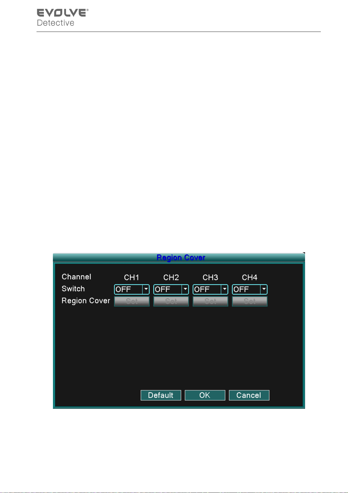
4.3.3 Region Cover
When the video image is affected by low light level or has reached the set sensitivity parameter,
the camera mask function will activate.
Picture 4.3 Region Cover
【Channel】Choose the corresponding channel number to set the channel. Choose the all option to set
every channel.
- 26 -
Page 31
【Switch】You can select ON or OFF status for each channel.
【Region Cover】When this channel status as ON, click Set and enter the area to be set. The area has 4
regions and you can move the cursor to set the areas.
Note:Pressing the “Default” button, will result in all confi gured setti ngs being replaced b y the default
settings.
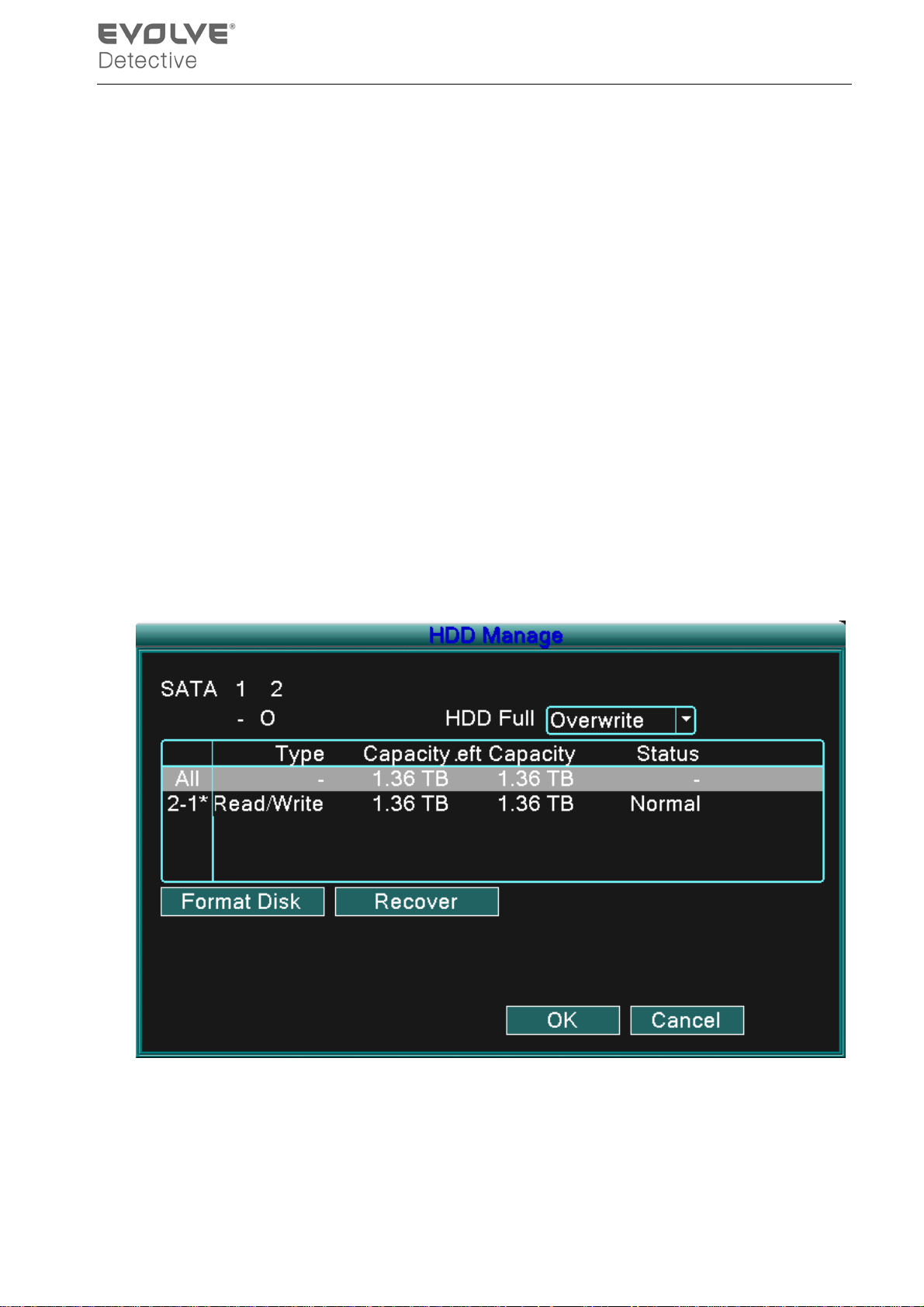
4.4 HDD Manage
Configure and manage the hard disk. The menu displays current hard disk information: hard disk
number, input port, type, status and overall capability. The operation include: setup the write-read disk,
read-only di sk, redun dant dis k, hard dis k form at, res ume def ault. Choose t he hard di sk and cli ck the
right function button to execute.
Note:Read/Write Disk: The equipment can write or read data.
Read-only Disk: The equipment can read data but cannot write data.
Redundant Disk: Double backup the video files in the write-read disk.
Picture4.4 HDD Manage
【Format Disk】Format the HDD which you selected and all data will lost.
【Recover】restores HDD to default status.
- 27 -
Page 32
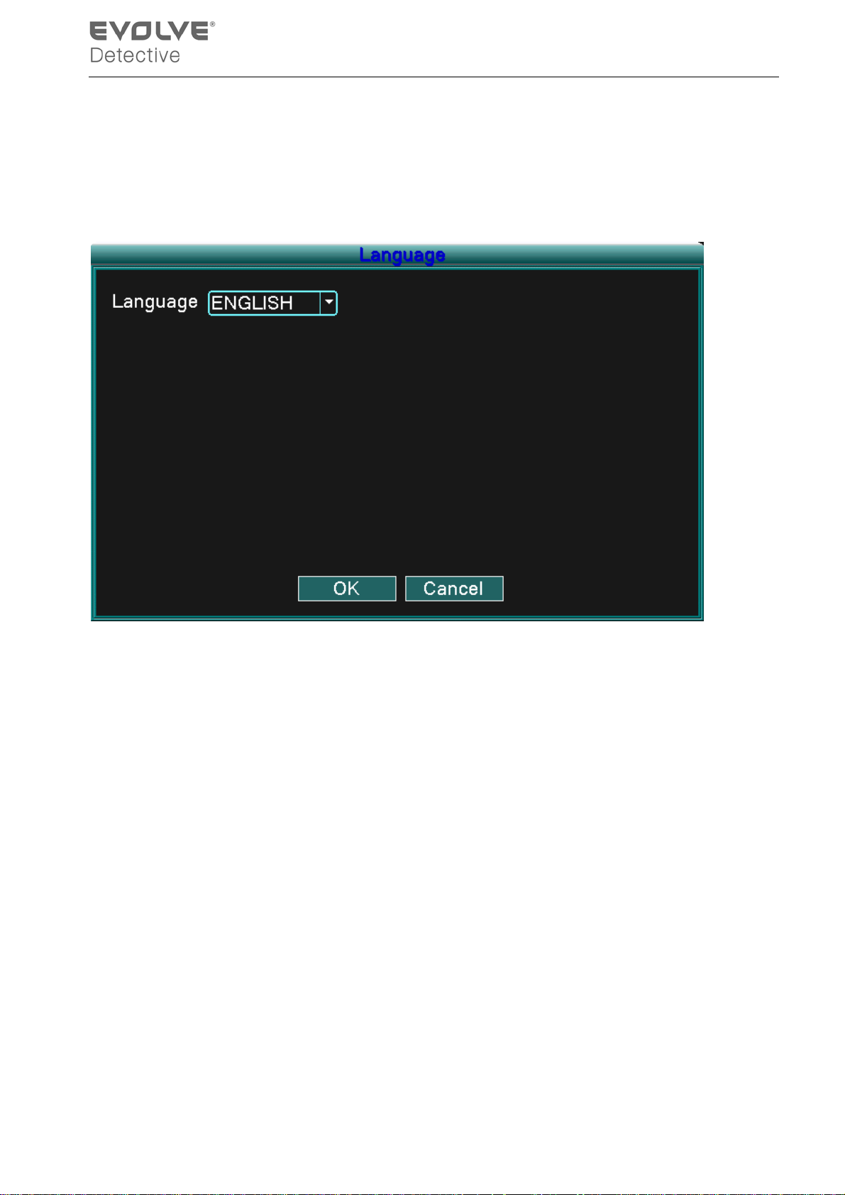
4.5 System setup
Set the system parameters, such as Language, Date/Time, Account, GUI Display, Video and Exit.
4.5.1 Language
Picture4.5 System Language
【Language】
You can select the language you want to use.
- 28 -
Page 33
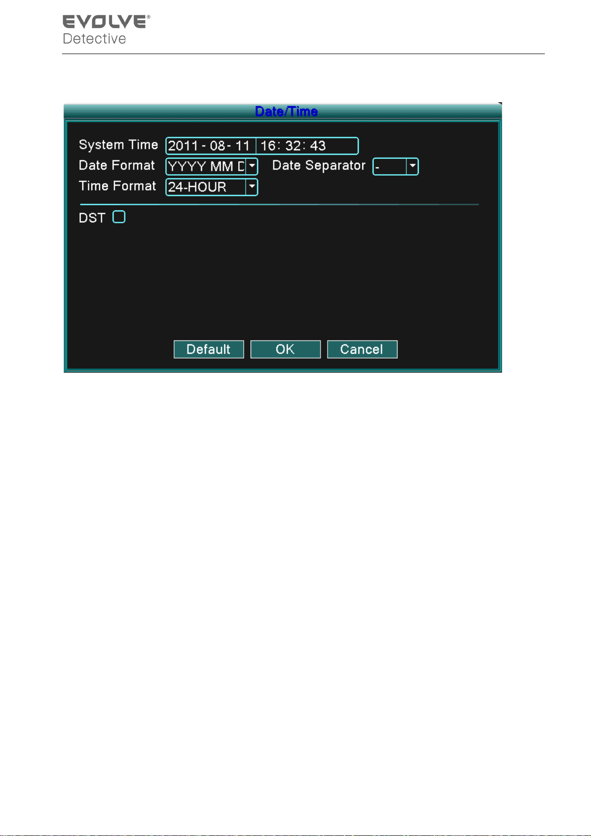
4.5.2 Date/Time
Picture4.6 Date/Time
【System time】Set the system data and time.
【Date format】Choose the data format: YMD, MDY, DMY.
【Date Separator】Choose list separator of the data format.
【Time Format】Choose time format: 24 hour and 12 hour format.
【DST】Choose “Daylight Savings Time” option.
- 29 -
Page 34
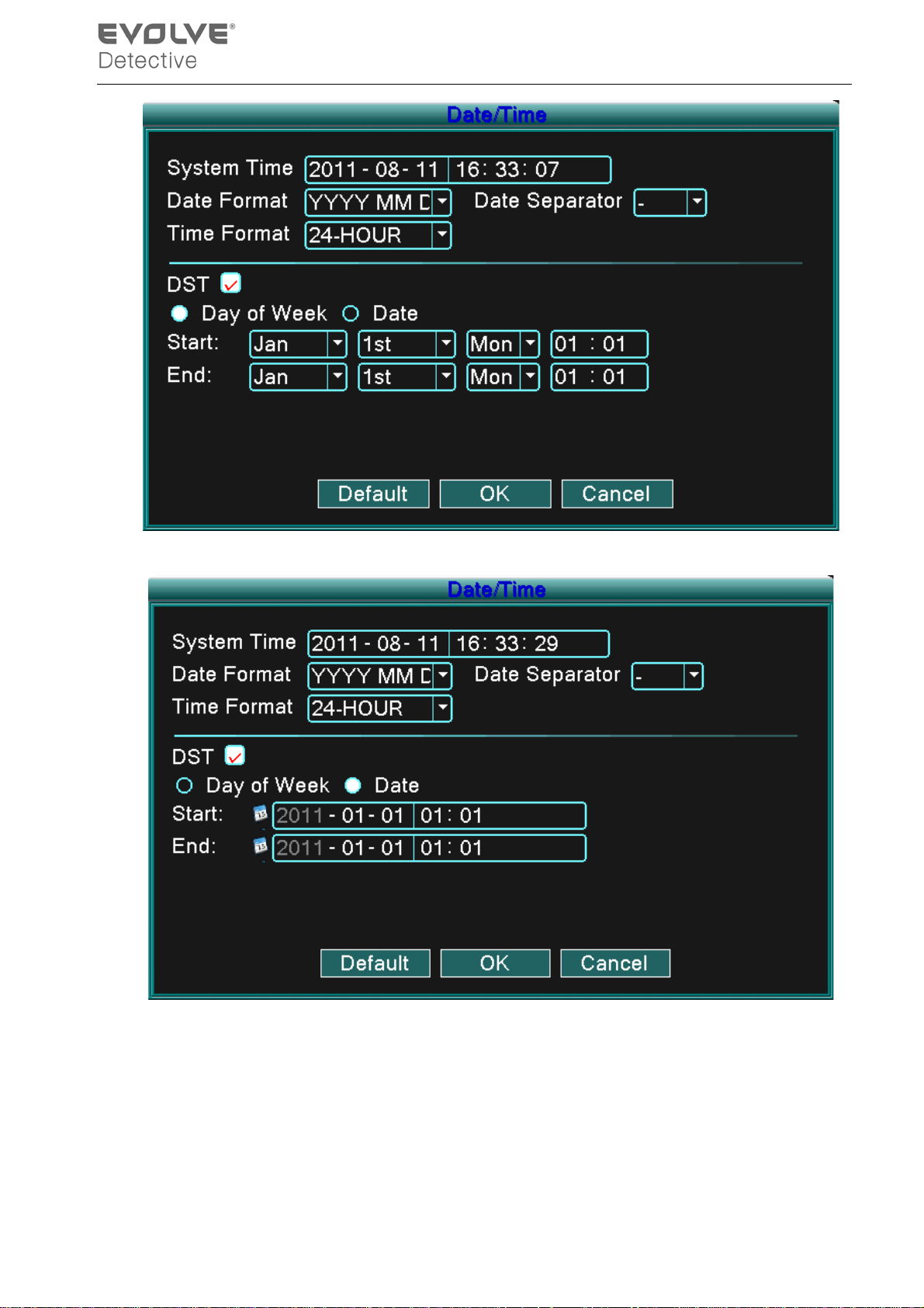
Picture 4.7 DST (week)
Picture 4.8 DST (date)
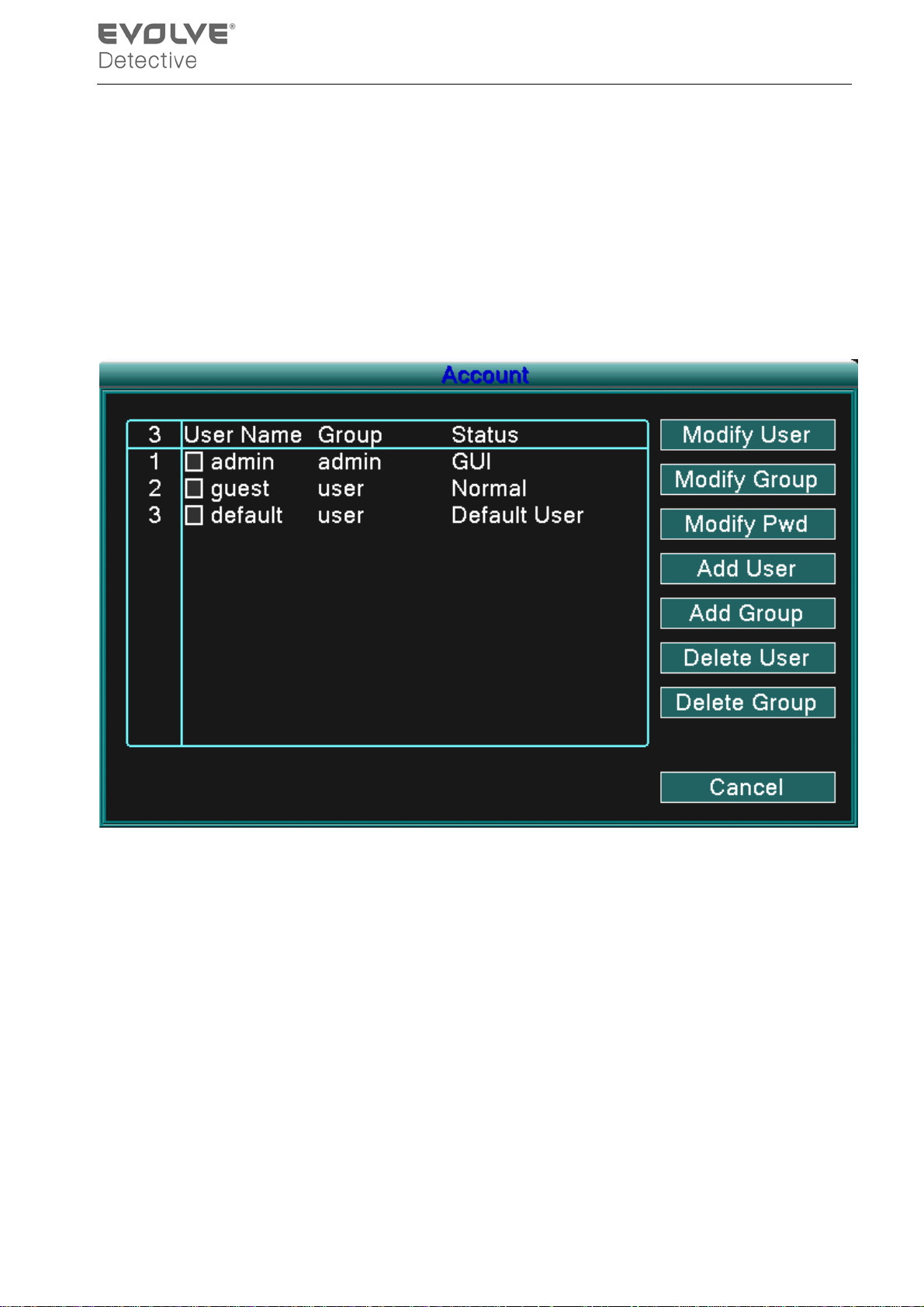
4.5.3 Account
Manage the user account.
Note:1. The character l ength i s 8 b ytes at m ost f or the user and us er group names. Blanks cannot b e
- 30 -
Page 35
used at the beginning or end of the character string but is acceptable as separation points within
the string. Legal characters include: letters, numbers, underlining, dash, and periods.
2. There is no limit with the user and user g r oups. You can add or del ete t h e user groups according
to user requirements. Th e factory set up includes: us er\admin. You can set the groups as you
wish. The user can appoint the administrator in the group.
3. The us er responsibilities incl ude group/ us er. The group and user nam es cannot be the s ame.
Each user can only belong to one group.
Picture 4.9 Account
【Modify User】Modify the existing user attributes.
【Modify Group】Modify the existing team attributes.
【Modify PWD】Modify the user password. You can set 1-6 bit passwords. Blanks cannot be used at
the begi nning or end of the char acter stri ng but is acceptab le as sep aration p oints
within the string.
Note:The user who possesses the administrator user control can modify his/her own or
other user’s passwords.
- 31 -
Page 36
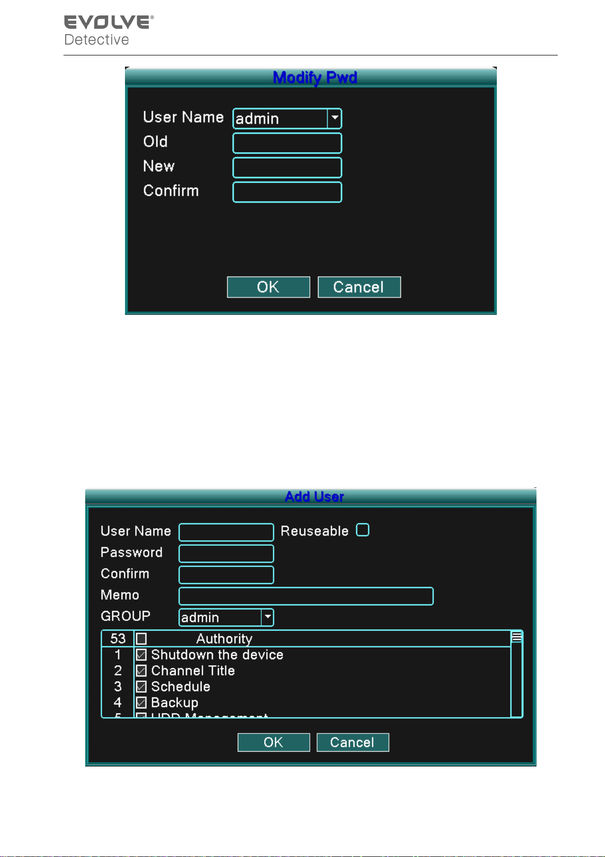
Picture 4.10 Modify Password
【Add user】Add a user in the team and set the user’s accountability. Enter the menu interface and
input the user name and password. Choose the team and choose the area of
accountability (area that can be used by multiple users at the same time).
Once the team is chosen the user oversees the subclass of the team.
The common user’s accountability should be set lower than the advanced user.
Picture 4.11 add user
- 32 -
Page 37
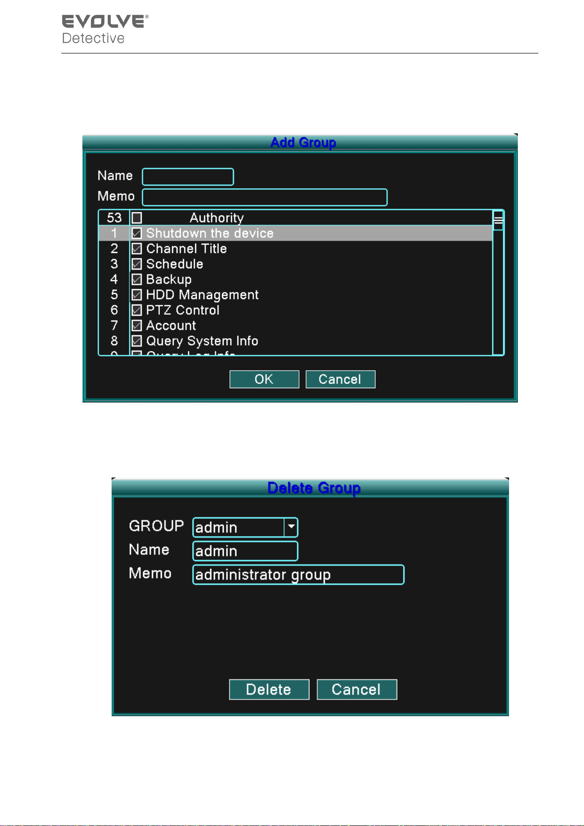
【Add Group】 Add a user team and set their range of accountability. There are 36 different possible
areas: shut down the device, real time surveillance, playback, recording setup, video
file backup, ETC.
Picture 4.12 Add Group
【Delete User】Delete the current user. Choose the user and click Delete User button.
【Delete Group】Delete the current group. Choose the group and click Delete Group button.
Picture 4.13 Delete Group
- 33 -
Page 38
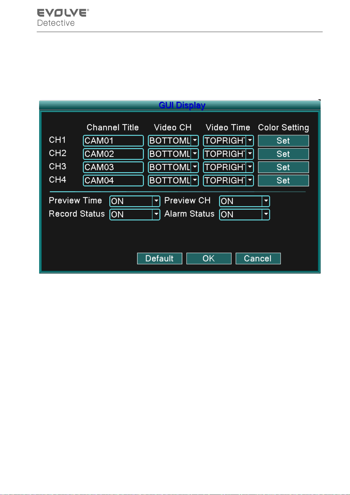
4.5.4 GUI Display
Configure the video output parameters including the front output mode.
Front output:The local preview mode includes: channel title, time display, channel title, record status,
and alarm status.
Picture 4.14 GUI Display
【Channel Title】Clic k the channel nam e m odify b utton an d enter the cha nnel n am e menu. M odif y
the channel name. The 16 Chinese characters and 25 letters are supportive.
【Preview Time】Displays the system data and time in the surveillance window.
【preview Channel】Displays the system channel number in the surveillance window.
【Record Status】Displays the system recording status in the surveillance window.
【Alarm Status】Displays the system alarm status in the surveillance window.
【Color Setting】Sets the selective image parameters (current channel for single window display and
cursor place for multi-window di spl ay) . You can press the “Set ” b utton to e nt er th e i nter face and set
the different parameters - the image parameters include: tonality, brightness, contrast, saturation.
- 34 -
Page 39
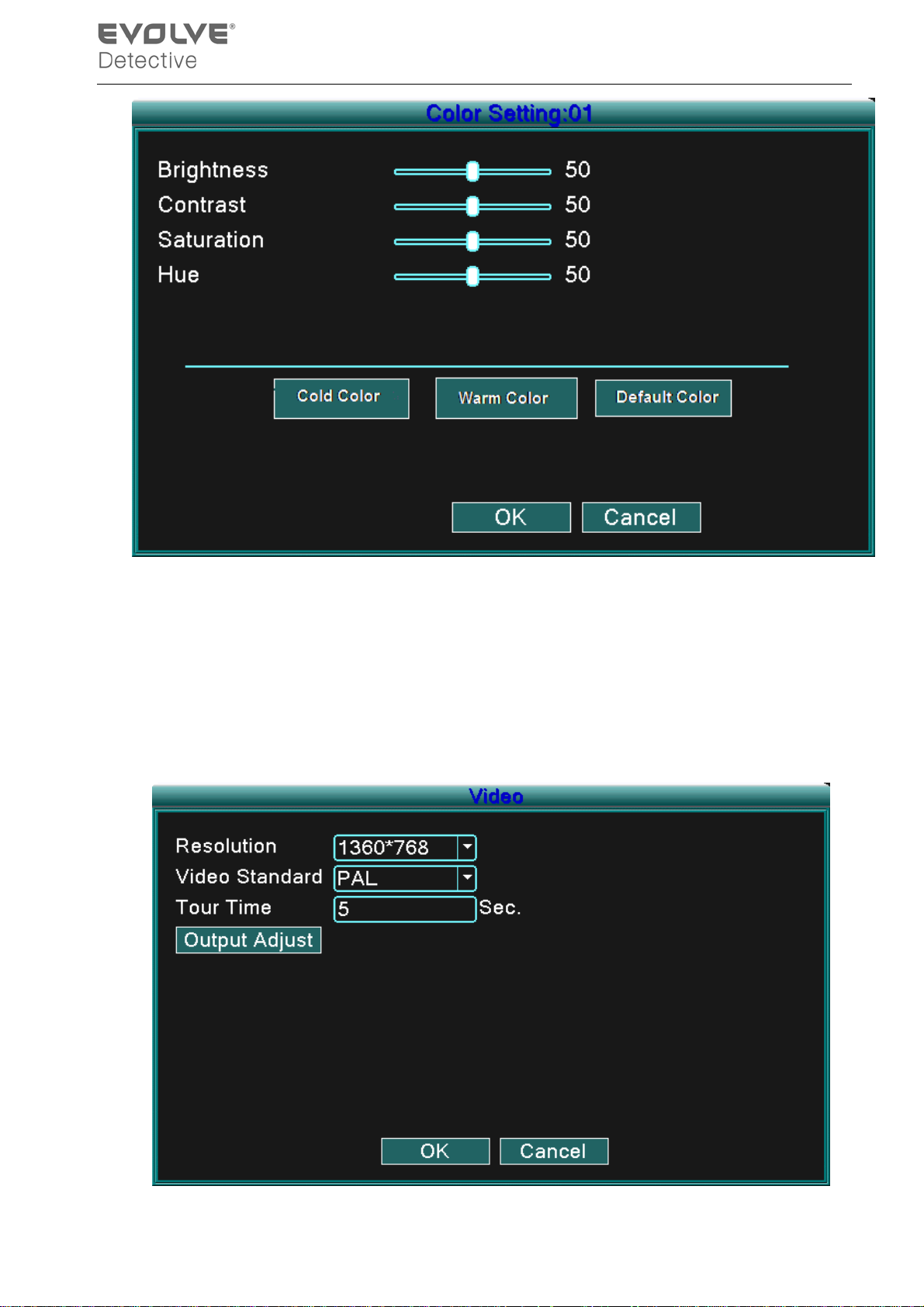
Picture 4.15 Color Setting
Note:Clicking the “Default” button will return all configured settings to default settings.
4.5.5 Video
Configur e video parameters in the loc al preview mode include : Resolution, Video Standar d, Tour
Time and Output Adjust.
- 35 -
Page 40
Picture 4.16 Video
【Resolution】Set display resolution.
【Video Standard】Set the video standard as PAL or NTSC.
【Tour Time】Set the patrol switch interval. The set range is 5-120 seconds.
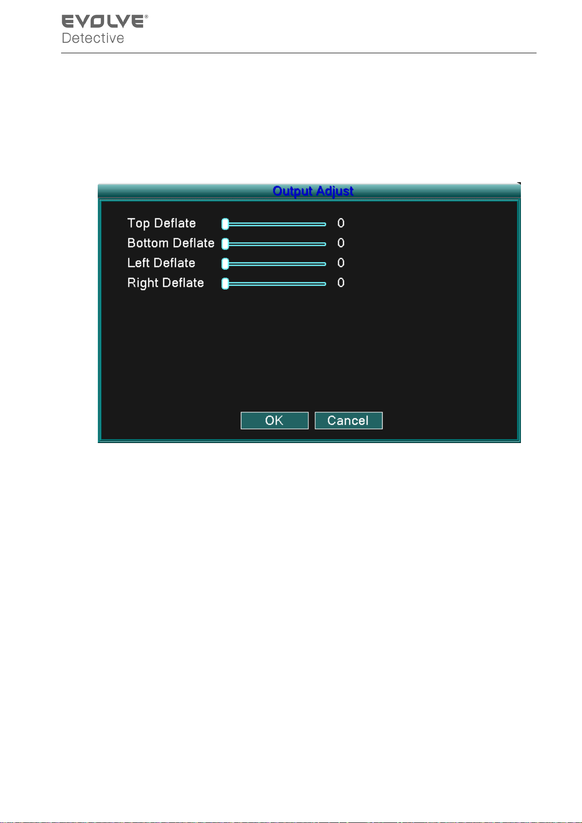
【Output Adjust】 Adjust TV output area parameters.
Picture 4.17 Output Adjust
4.6 Advanced
Configure advanced p aramet ers:
Alarm Set, Version, Motion Detect, Mobile Monitor, Auto Maintain and Network.
4.6.1 Alarm Set
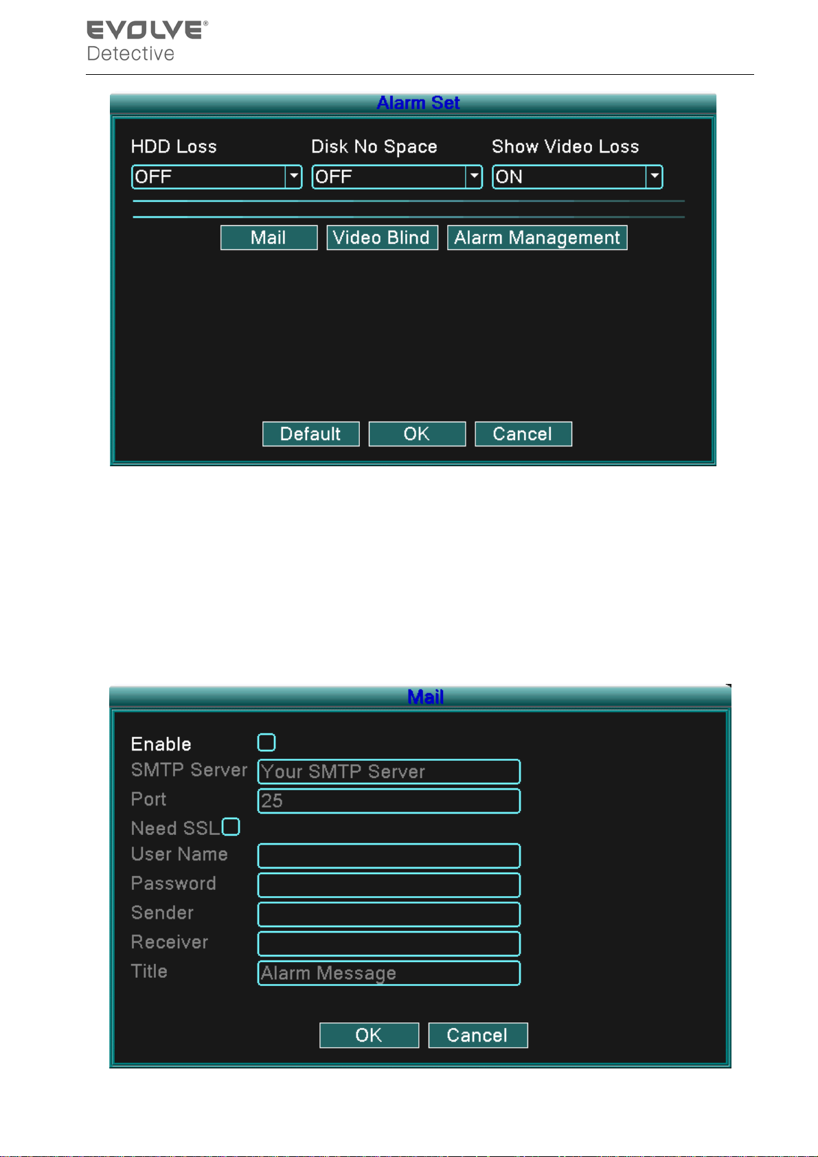
Alarm f unctions include: HDD Loss, Disk No Space, Show Video Loss, Mail, Video Blind, a nd Alarm
Management.
- 36 -
Page 41
Picture 4.18 Alarm Set
According to your configured parameters, when an event occurs the device will alert you by:
displaying a message, sounding a buzzer, and/or sending an email.
4.6.1.1 Mail
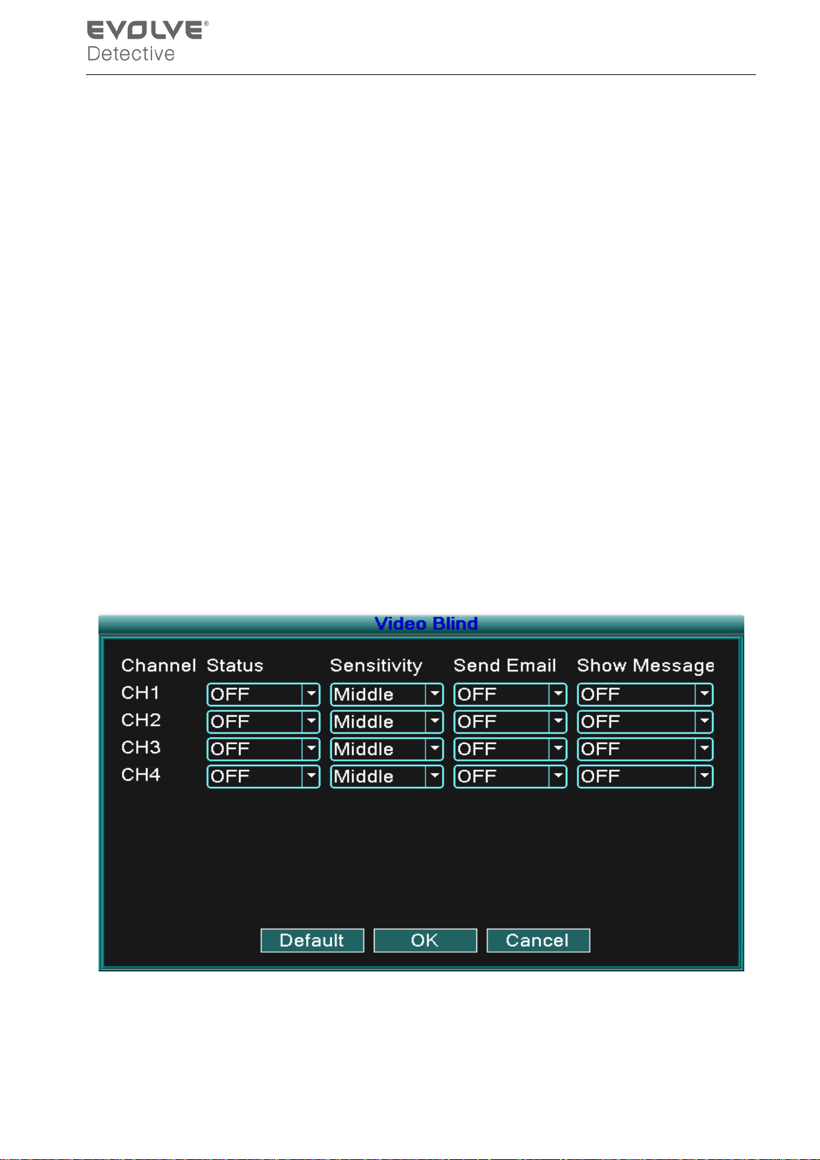
If the alarm is turned on, an email regarding alarm information will be sent to all appointed
addresses.
- 37 -
Page 42
Picture 4.19 Email
SMTP server: Em ai l serv er address . It coul d b e an I P address or dom ai n nam e. Dom ain nam e can
be translated only if the correct DNS is configured.
Port: Email server port number.
SSL: Requires Secure Socket Layer protocol to login.
User Name: Email server user name.
Password: Input users corresponding password.
Sender: Alarm notice sender’s email address.
Receiver: Email address of appointed receivers when the alarm is turned on. You can set a
maximum of three receivers.
Title: The name you assign for the alarm notification that is sent.
4.6.1.2 Video Blind
When the v ideo im age is obscured by the env ironm ent, such as excessive b rightness or reachi ng
the set sensitive parameters, the c amer a mask function is turned on and t he link ed function ( such as
Send email, show message, or buzzer) is turned on.
Picture 4.20 Video Blind
- 38 -
Page 43
4.6.1.3 Alarm Management
Picture 4.21 Alarm Management
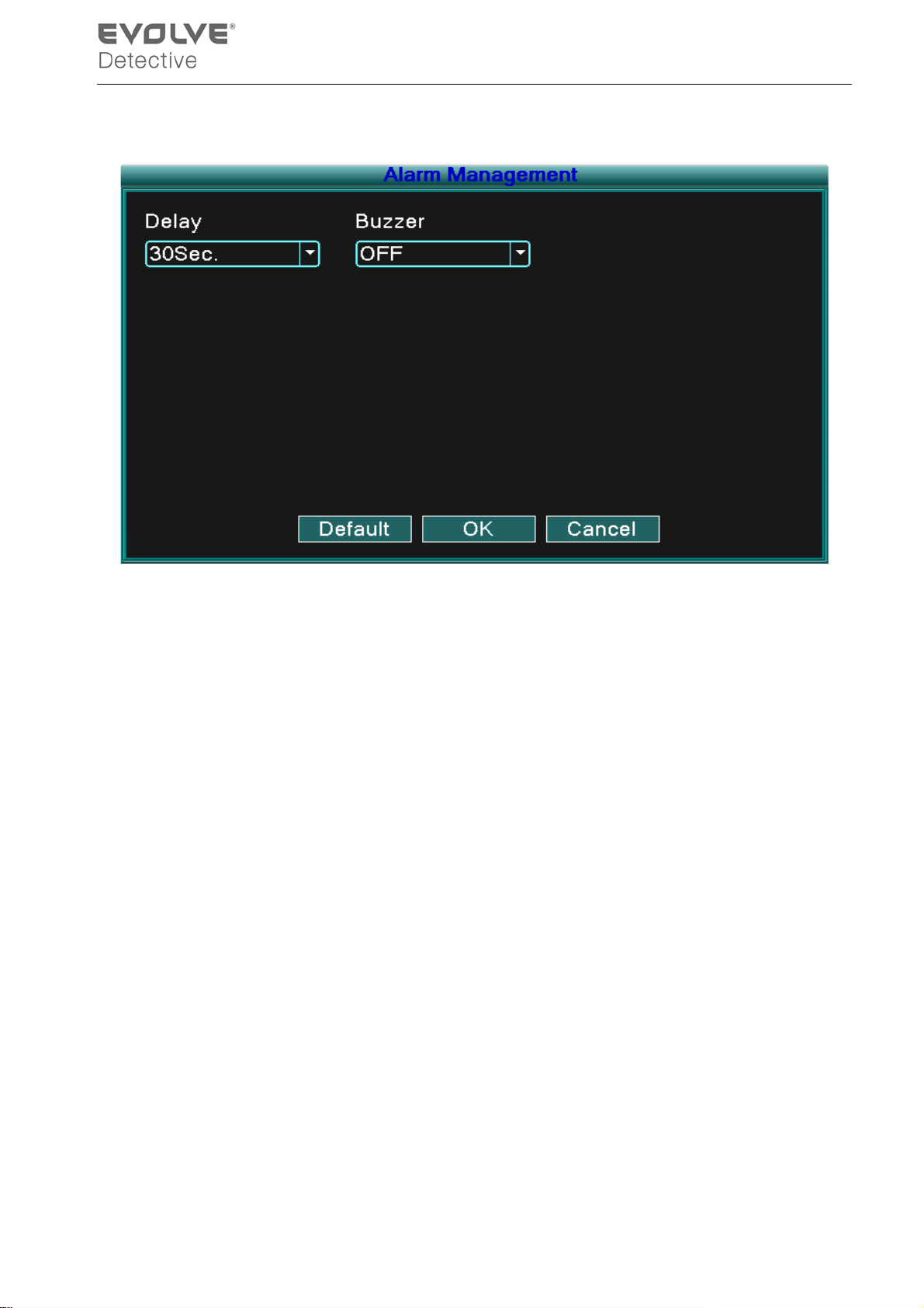
【Delay】Set the r ecord tim e When an event (HDD Loss, Disk No Space, Video Los s, and Video
Blind) occurs.
【Buzzer】Y ou can set the Buzzer status as ON or OFF.
4.6.2 Version
Displays basic i nform ation reg arding the system such as : hardw are inf ormati on, softw are edition,
and issue data, ETC.
- 39 -
Page 44
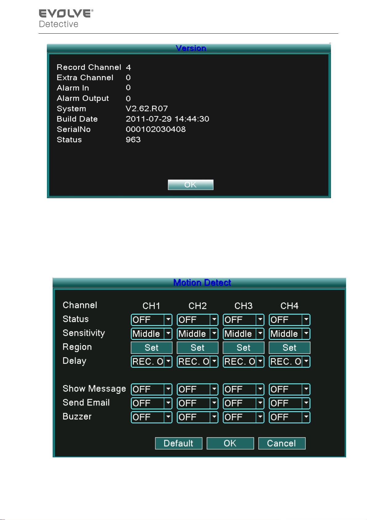
Picture 4.19 Version
4.6.3 Motion Detect
When the system detec ts a motion s ignal that reaches t he set sens itivi ty point, th e motion d etect
alarm activates and the linked function (such as Send email, show message, or buzzer) is turned on.
Picture 4.20 Motion Detect
- 40 -
Page 45

【Channel】Choose the set motion detect channel.
【Status】Indicates if the motion detect function is on or off.
【Sensitivity】Choose six sensitivity options.
【Region】Click setup and enter the setup area. The area is divided into an 8x8 grid. Green block is
the current cursor area, yellow blocks are the dynamic detect defensive area, and black
blocks are the unfenced areas. Y ou can set the area by dragging the mouse to draw the
area.
Picture 4.21 Region
【Delay】Delay a f ew m oments and stop w hen the alarm state is tur ned off. The r ange is 10~ 300
seconds.
【Delay】When alarm is over, recording will last 10~300sec and then stop.
【Show message】The alarm information dialog box will open in the local host computer screen.
【Send EMAIL】Means sending an email to user when the motion detect alarm is activated.
Note: Set in the [Net Service] to send email.
【Buzzer】Buzzer alarm will sound twice when the motion detect alarm is activated.
4.6.4 Mobile Monitor
To monitor the system by mobile device, please make a router mapping of this port and use CMS to
monitor and operate it by protocol.
- 41 -
Page 46
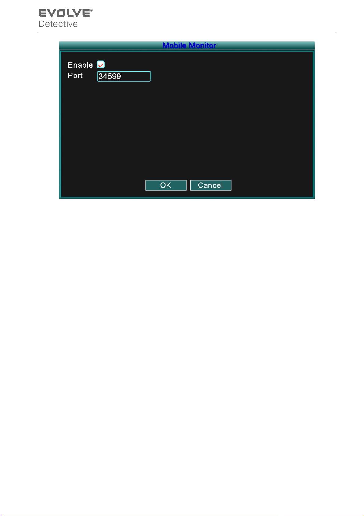
Picture 4.22 Mobile Monitor
【Enable】Select it to activate function.
【Port】 The port used for m obi le m onitori ng w hich you nee d to m ake a rout er m appi ng of if w ant to
monitor by mobile device.
4.6.5 Auto Maintain
The user can set parameters to include:
Auto reboots time, System Upgrade, Default Settings, Log, Log out, Shut down, reboot, ETC.
- 42 -
Page 47
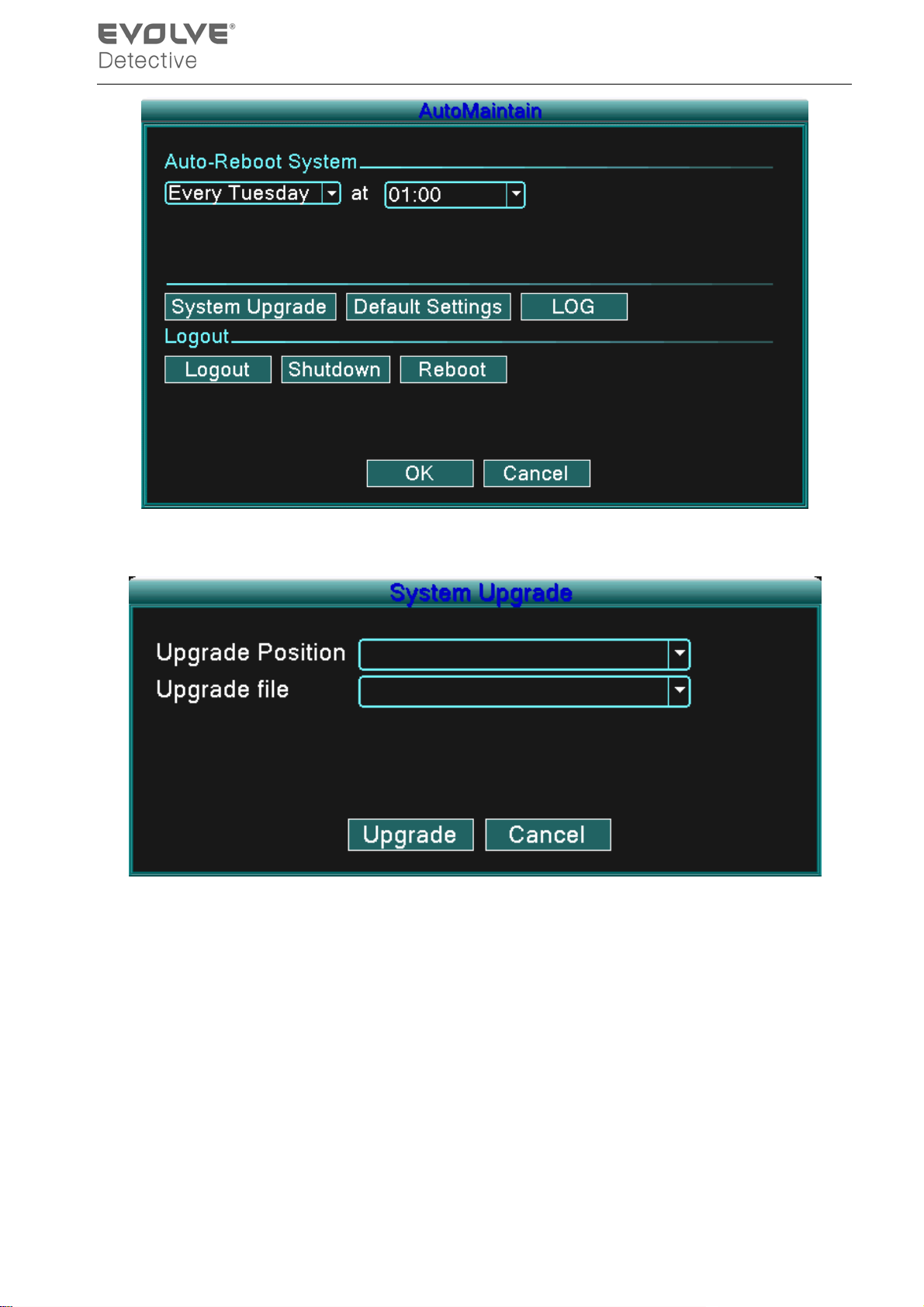
Picture 4.23 Auto maintain
【Upgrade】
Picture 4.25 Upgrade
Upgrade Position: Choose USB interface.
Upgrade file : Choose the file which needs upgraded.
Note: After Upgrade operation, the DVR will reboot.
【Default Settings】
The system restore to the default setup. You can choose the items according to the menu.
- 43 -
Page 48
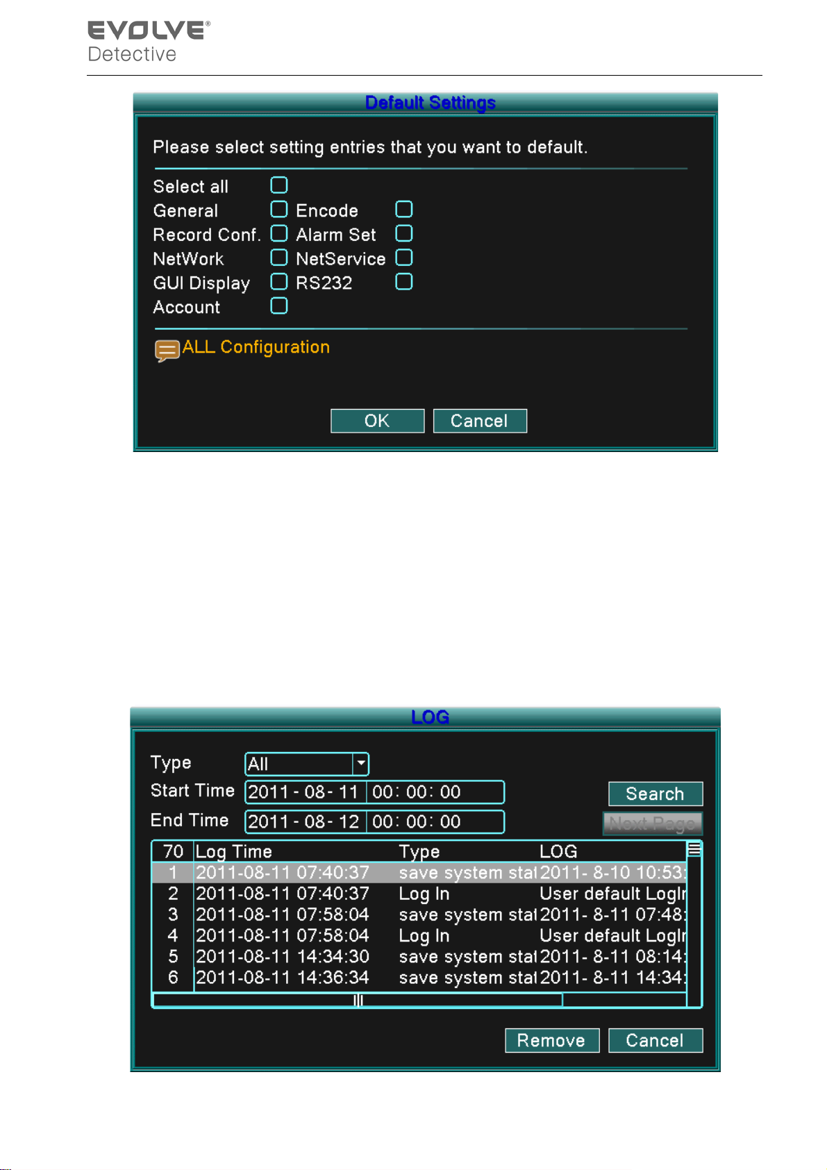
Picture 4.24 Restore
【Log】
Look up system log according to the set mode.
Log information includes: system operation, configuration operation, data management, alarm affair,
recordi ng op er ati on, user management, and file management, ETC. Set the t ime secti on to l ook up
and click the l ook up b utton. The log inf orm ati on w ill disp lay as a list (one page equals 128 i tem s) .
Click Page up or Page down button to search log and click Remove button to clear that log
information.
- 44 -
Page 49
Picture4.26 LOG
【logout】Quit the menu and password is required for next entry.
【shutdown】Quit the system. Power off DVR.
【reboot】Quit the system. Reboot system.
4.6.6 PTZ Configure
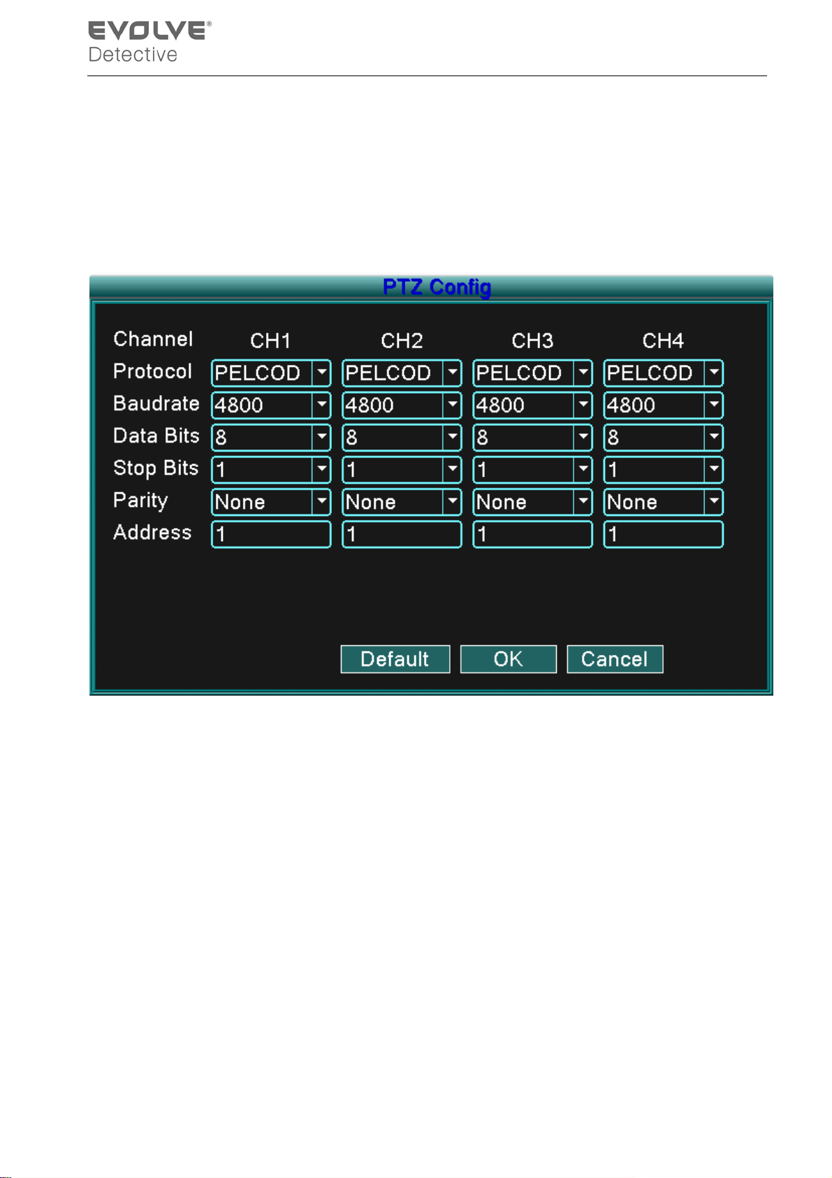
Picture 4.27 PTZ Configuration
【Channel】Choose the dome camera input channel.
【Protocol】Choose the corresponding dome protocol. (PELCOD as an example)
【Baud rate】Choose the corresponding dome baud rate length. You can control the PTZ and
division. Default: 115200.
【Data bits】Include 5-8 options. Default: 8.
【S top bits】Include 2 options. Default: 1.
【Parity】Includes odd check, even check, sign check, blank check. Default: void.
【Address】Set as the corresponding dome address. Default: 1.(Note:The address must be
consistent with the dome address.)
Note:Clicking the “Default” button will replace all configurations with default settings.
- 45 -
Page 50
4.6.7 Network
Network setup includes:
Static IP, DHCP, PPPoE, DDNS, UPNP, ETC.
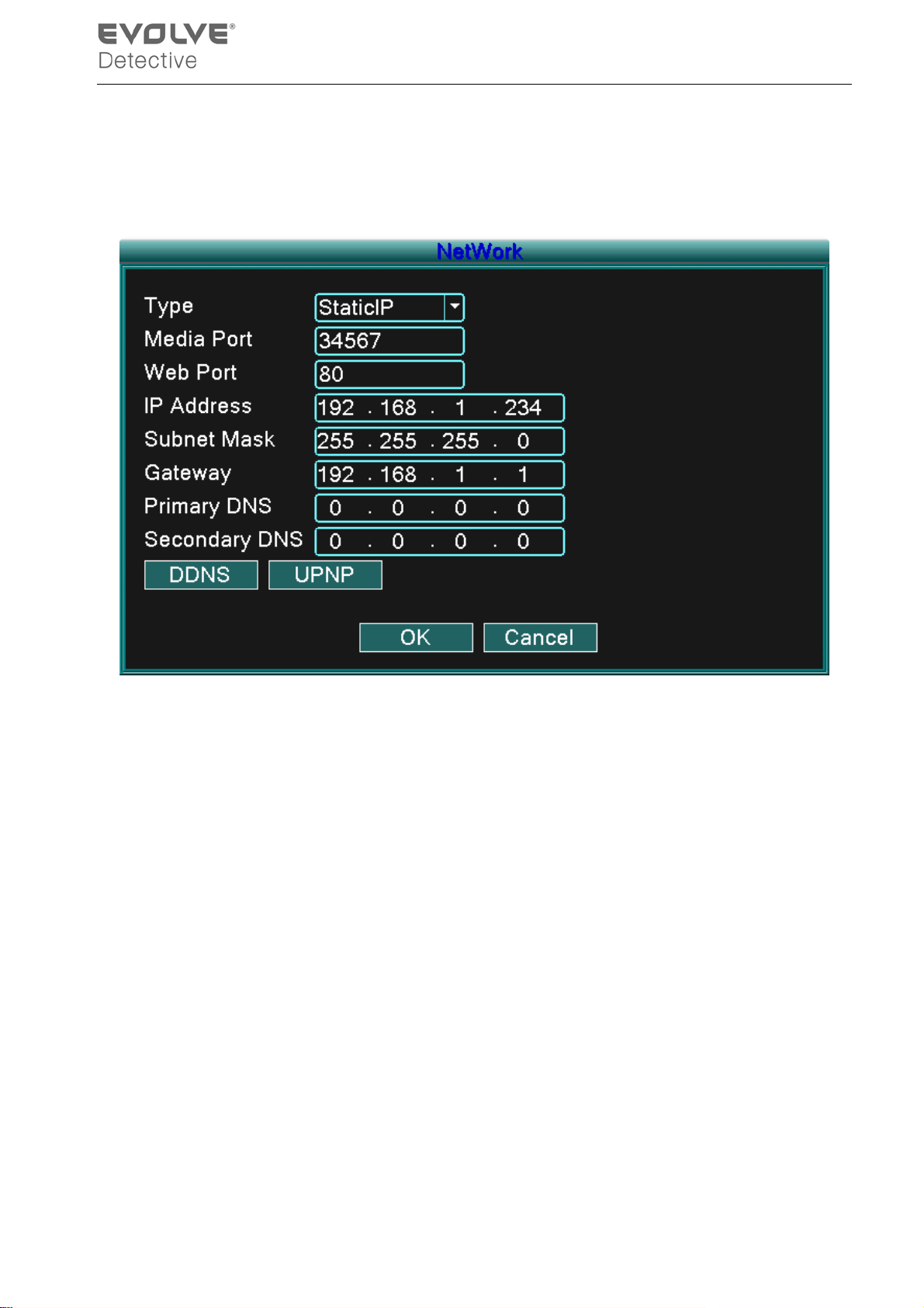
【Static IP】
Picture4.28 Network
【Type】select Static IP mode.
【TCP/Media port】Defaul t: 34567.
【HTTP/Web port】D efaul t: 80.
【IP addr es s】Set the IP address . D efaul t: 192.168.1.10.
【Subnet mask】Set the subnet mask c ode. Def ault: 255. 255.255.0.
【Gateway】Set the def aul t gatew ay. D efaul t: 192.168.1.1.
【DN S s etup】 Domain N ame Server. It translates the dom ain name into an IP address. The IP
address is given by networ k provider. The addres s must be set and t he system
rebooted to b ecome eff ec tive.
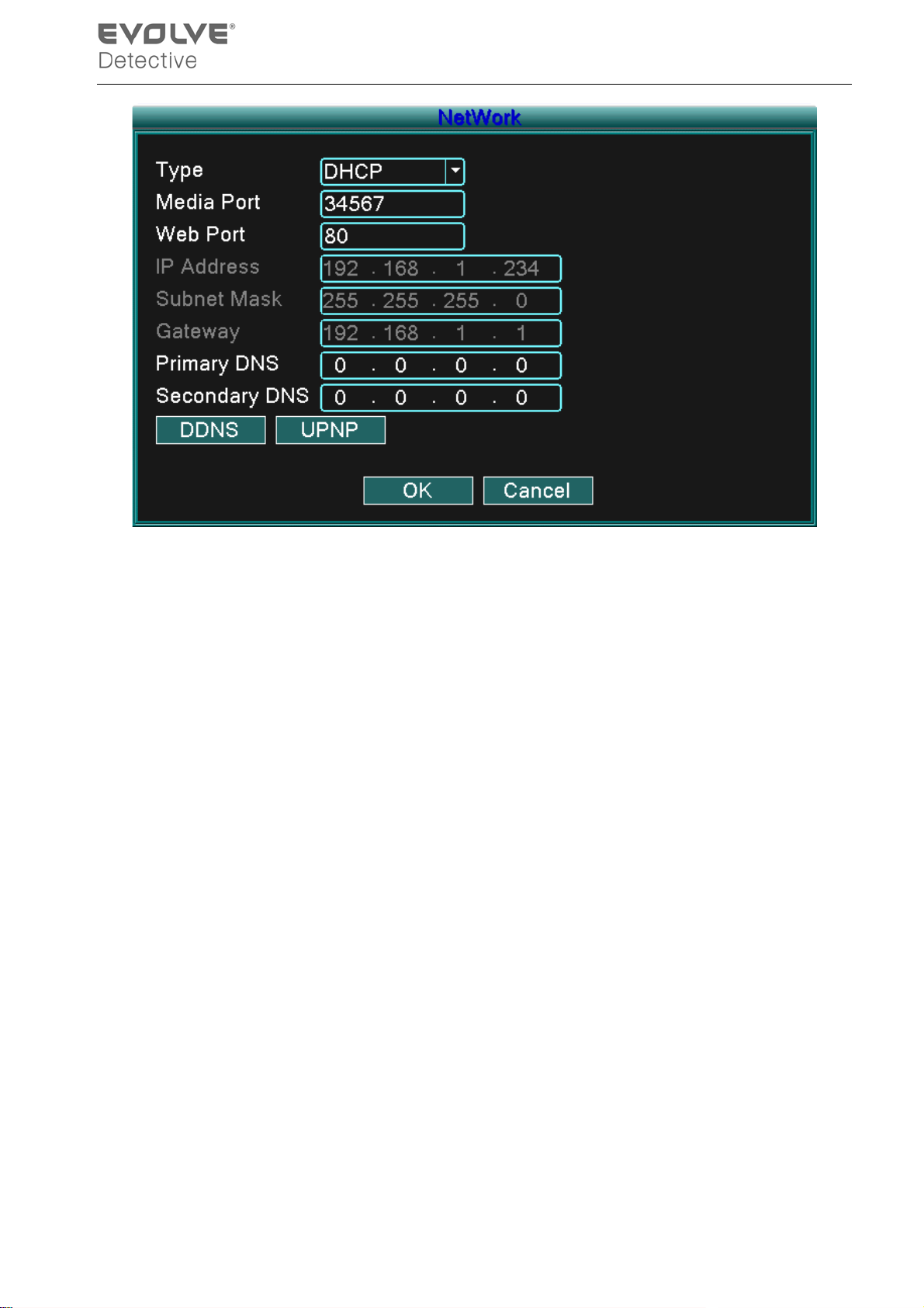
【DHCP】Get the IP address from the router automatically.
- 46 -
Page 51
Picture4.29 DHCP
【Type】select DHCP IP mode.
【TCP/Media port】Default: 34567.
【HTTP/ Web port】Default: 80.
【DNS setup】Domain Name Server. It translates the domain name into IP address. The IP
address is given by the network provider. The address must be set and the
system rebooted to becom e eff ectiv e.
- 47 -
Page 52
【PPPoE】
Picture 4.30 PPPOE
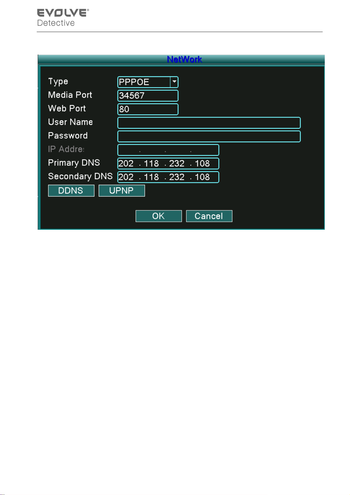
Input the user name and password that ISP(Internet service provider)provides. After saving reboot
your system to become effective. Then the DVR will build a network connection based on the
PPPoE. The IP address will change into a dynamic IP address after the above operation is
successful.
Operation:After the PPPoE dialup is successful the IP address [IP address] is obtain a nd ent er ed
as the current IP address and then use this IP address to visit the DVR through user port.
【DDNS】
Is the abbreviation of Dynamic Domain Name Server.
Local domain name:Provide the domain name registered by DDNS.
User name:Provide the account name registered by DDNS.
Password:Provide the password registered by DDNS.
When the D DNS is successful ly configured and star ted, you can connect b y entering the dom ain
name in the IE address column to monitor.
Note:The DNS s etup must be configured correctly in the networ k setup.
- 48 -
Page 53
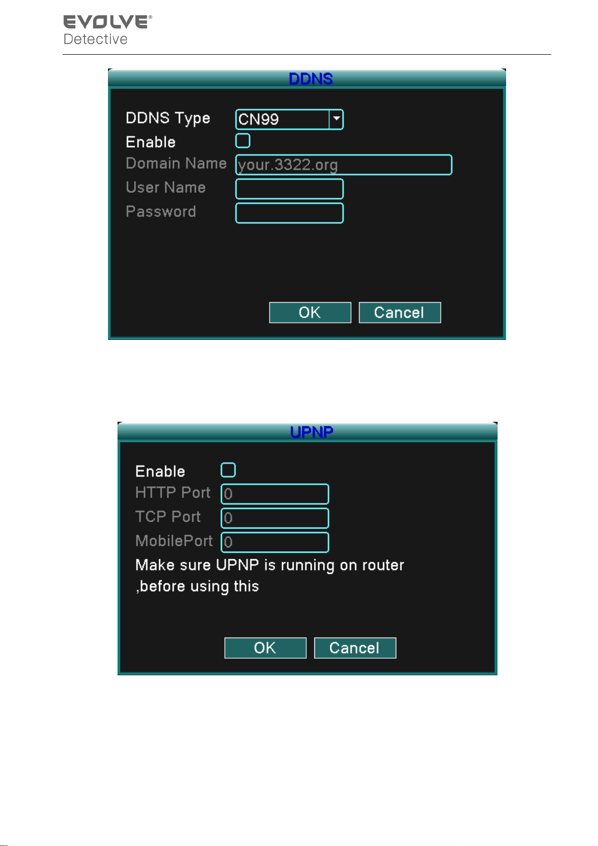
Picture 4.31 DDNS setup
【UPNP】UPNP protocol can auto port forwarding on router, make sure UPNP is running on router
before using it.
Picture 4.32
【Enable】Choose Enable to make sure all UPNP settings are available
【HTTP】Router will automatically distribute HTTP port for the device, when IE viewing, it will re qui re
this port setting (e.g. 60.12.9.26:66)
- 49 -
Page 54

【TCP】Router will automatically distribute TCP port for the device, when monitoring via CMS, it will
require this port setting.
【Mobile Port】Router will automatically distribute Mobile Port for the device, when mobile monitor, it
will require this port setting.
- 50 -
Page 55

5 FAQ and maintenance
5. 1 FAQ
1. The DVR cannot boot up normally.
Possible reasons:
1. The power supply is not correct.
2. Verify power switch is ON.
3. Power supply may be damaged.
4. The program update is incorrect.
5. The hard disk is damaged or the hard disk cables are broken or not connected.
6. The front panel array is damaged.
7. The main board of the DVR is damaged.
2. The DVR reboots automatically or stops working after a few minutes.
Possible reasons:
1. The input voltage is not stable or too low.
2. The hard disk is damaged or the hard disk cables are broken or not connected.
3. Video signal is not stable.
4. Too much dust or poor environment conditions.
5. The DVR hardware is damaged.
3. System cannot detect hard disk.
Possible reasons:
1. The hard disk power supply line is not connected.
2. The cables of the hard disk are damaged or not connected properly.
3. The hard disk is damaged.
4. The SA TA port of main board is damaged.
4. There are no video outputs in singl e channel, multiple channels, or all channels.
Possible reasons:
1. The software program and drivers may need to be updated.
2. The image brightness is set to 0. Please restore the default settings.
- 51 -
Page 56

3. There is no video input signal or the signal is too weak.
4. The channel protection or the screen protection is set.
5. The DVR hardware is damaged.
5. Real-time image problems such as the image col or or the brightness dis torti on.
Possible reasons:
1. When using the BNC output, the option between the N mode or PAL mode is incorrect and
the image becomes black and white.
2. The DVR is not matched the monitor impedance.
3. The v ideo trans mi ssion distance is too far or the loss of t he video transm issi on line is too
large.
4. The color and brightness setting of the DVR is incorrect.
6. I cannot find the video files in local playback mode.
Possible reasons:
1. The data line of the hard disk is damaged.
2. The hard disk is damaged.
3. Update the program with the original program files.
4. The video files to look up are hidden or within another file.
5. The recording function is not set to ON.
7. The local video is not clear.
Possible reasons:
1. The image quality is bad.
2. The reading program is incorrect, reboot the DVR.
3. The data line of the hard disk is damaged.
4. The hard disk is damaged.
5. The DVR hardware is damaged.
8. There is no audio signal in the surveillance window.
Possible reasons:
1. It is not an active audio channel.
2. The audio files are damaged.
3. The audio lines are damaged.
- 52 -
Page 57

Ω
4. The DVR hardware is damaged.
9. There is audio signal in the surve i llance window but no audio signal during playback.
Possible reasons:
1. The audio option is not chosen in the settings.
2. The allocated channel is not connected with the video.
10. The time is wrong.
Possible reasons:
1. Incorrect settings.
2. The battery is bad or the voltage is too low.
3. The DVR hardware is damaged.
11. The DVR cannot control the PTZ.
Possible reasons:
1. There is something wrong with the PTZ.
2. The settings, connection, or the installation of the PTZ decoder is incorrect.
3. The connections are not correct.
4. The DVR PTZ settings are incorrect.
5. The protocols of the PTZ decoder and the DVR are not matched.
6. The address of the PTZ decoder and the DVR are not matched.
7. W hen multipl e decoders are connect ed, the far port of the P TZ decoder line A (B) must
connect to a 120
resi stance to reduce t he refl ection, oth erwise t he PTZ control is not
stable.
8. The distance is too far.
12. The motion detect function is not working,
Possible reasons:
1. The time range setting is incorrect.
2. The motion detect area setting is incorrect.
3. The sensitivity is too low.
4. Limited by some hardware version.
13. I cannot login via web or CMS.
Possible reasons are as followed:
- 53 -
Page 58

1. The systems are Windows® 98 or ME. Update to Windows® 2000 SP4 or higher version.
2. ActiveX is disabled.
3. The driver version must be higher than dx8.1. Update the display card driver.
4. Network connection failure.
5. Network setting issues.
6. Invalid password or user name.
7. The CMS does not match the DVR program version.
14. The image is not clear or there is no image in network preview state or video file playback
state.
Possible reasons:
1. Network is not stable.
2. The user machine resources are limited.
3. Choose the play-in-team mode in the network setup of DVR.
4. The region shelter or channel protection is set.
5. The user has no surveillance authority.
6. The real-time image of the hard disk recording machine itself is not clear.
15. Network connection is not stable.
Possible reasons:
1. Network is not stable.
2. IP address conflict.
3. MAC address is conflict.
4. The net card of the DVR is bad.
16. There is s omething wrong with the USB backup or writing to a CD.
Possible reasons:
1. The rewritable CD drive and the hard disk share the same data lines.
2. The data file is too large, stop recording and backup.
3. The data exceeds the backup storage limit.
4. The backup equipment is not compatible.
5. The backup equipment is damaged.
17. The keyboard cannot control the DVR.
- 54 -
Page 59

Possible reasons:
1. The serial port of the DVR is not set correctly.
2. The address is not correct.
3. W hen multi ple transf ormers are connected, t he power supply is not larg e enough. Please
give each transformer an individual power supply.
4. The distance is too far.
18. The remote control is not working,
Possible reasons:
1. The remote control address is not correct.
2. The remote control distance is too far or the angle is too large.
3. The batteries are low on power.
4. The remote control IR on the front panel of the DVR is damaged.
19. The storage time is not enough.
Possible reasons:
1. The hard disk capacity is too small.
2. The hard disk is damaged.
20. The downloaded files cannot play.
Possible reasons:
1. There is no media player.
2. There is no DX8.1 software or higher edition.
3. There is no DivX503 Bundle.exe file to play AVI video files.
4. The DivX503 Bundle.exe and ffdshow-2004 1012 .exe files must be installed in the
Windows® XP system.
21. I cannot reme mber the advanced code or ne twork code in the local menu operation.
Please contact your local IP service.
5.2 Maintenance
1. Please ensure the system is grounded to prevent video or audio signal interference and the
DVR from static or inductive electricity.
2. Do not disconnect the video signal line, RS-232 port, or RS-485 port with the power on.
- 55 -
Page 60

3. Do not connect a TV to the local video output port (VOUT) of DVR. It will damage the video
output circuit.
4. D o not turn t he p ower switc h of f di r ec tl y. Please use t he shutdown function in the m enu or
click the turn-off button in the panel to protect the hard disk.
5. Please keep the DVR away from heat resource.
6. Please keep the DVR ventilated for better heat radiation.
7. Please check the system and maintain regularly.
- 56 -
Page 61
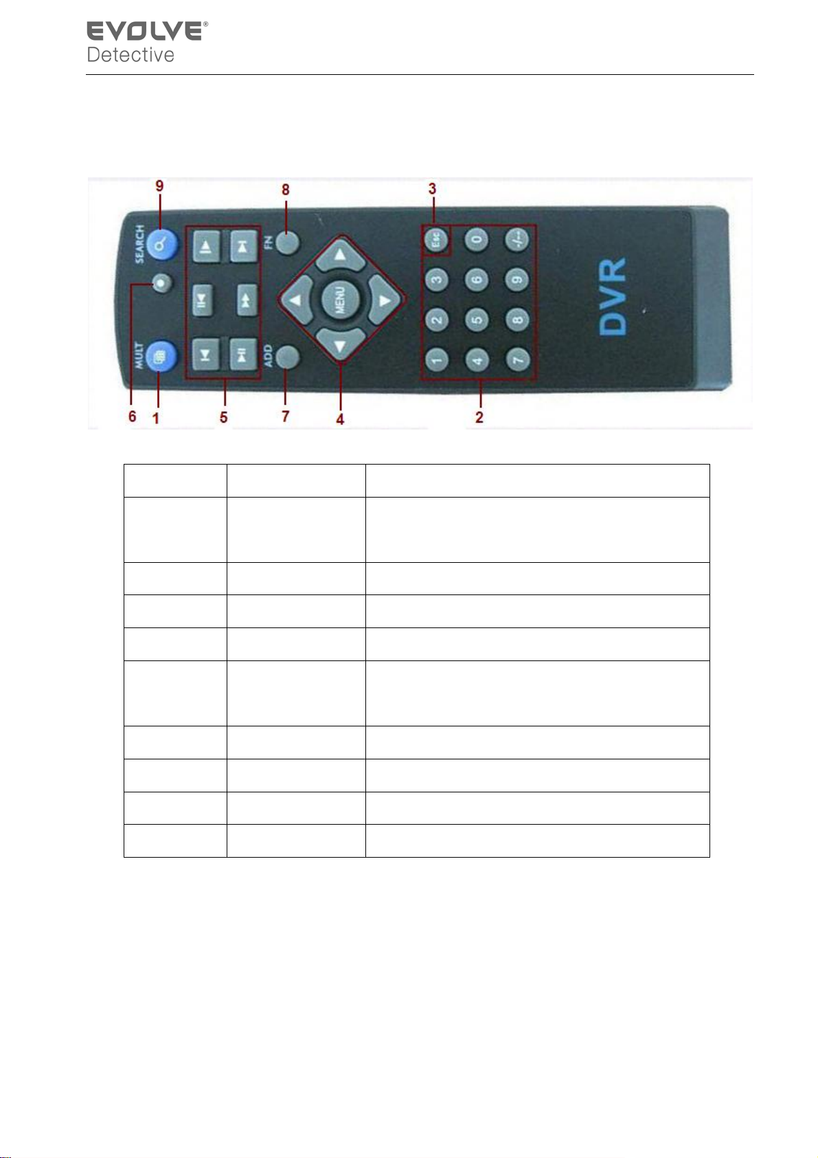
Appendix 1. Remote control operation
Item number Name Function
1 Multi-window
button
2 Numeric button Code input/number input/channel switch
3
4 Direction button Up, Down, Left, Right, and Enter/Menu button.
5 Record/Playback
6 Record mode Enter short menu as “record mode” button
7 ADD Input the number of DVR to control
8 FN Assistant function
9 Search Search record files to playback.
【Esc】
control
Split screens button
Exit button
Control recording/playback
- 57 -
Page 62
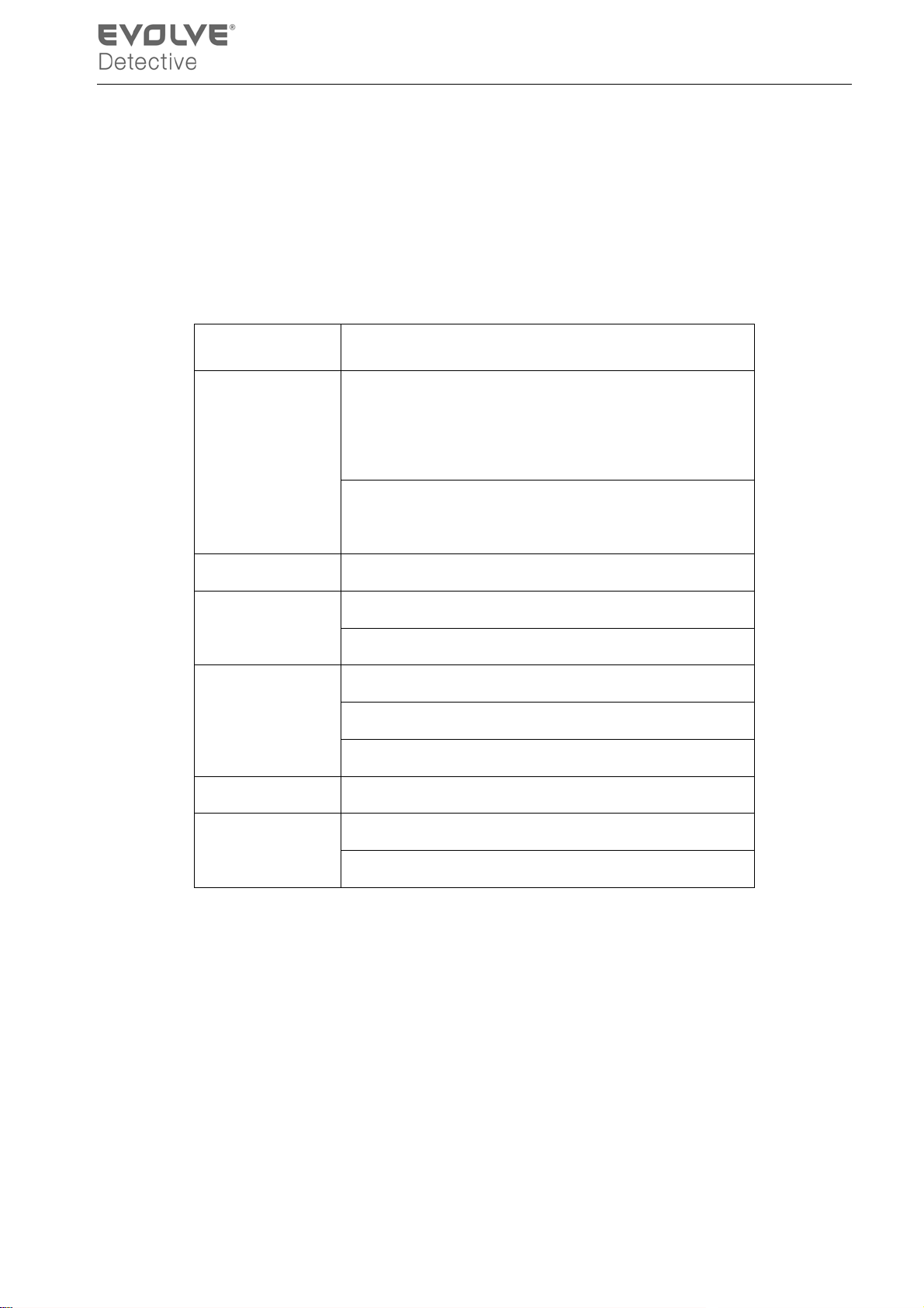
Appendix 2. Mouse operation
The USB ports support mouse operations.
NOTE: Units with front and rear mouse USB ports can only uti lize one port at a time – if a USB device is
connected to one of the ports the oth er is automatically deactivated. The bottom rear USB port is
designated for USB backup drives.
Operation Function
Double click one item in the file list to playback the
video.
Double lef t click
Left click Choose the associated function in the menu
Right click
Press middle
button
Move mouse Choose the widget or move the item in the widget
Drag mouse
Double click the playback video to zoom in or out.
Double click the channel to make it display full screen.
Double click again to resume the multi-window display.
Open the desktop shortcut menu in a preview state
Current shortcut menu in the main menu
Add or subtract number in the number setting
Switch the items in the combo box
Page up or down in the list
Set the motion detect area
Set the cover area
- 58 -
Page 63

Appendix 3.Hard disk capability calculation
Verify the following when installing the hard drive in the DVR for the first time:
1. Hard disk capacity
There is no limit for recording machine. We recommend 120G~ 250G sizes to keep better
stability.
2. Overall capacity option
The hard disk capacity formula is:
Overall capacity(M)= channel number*time(hour)*capacity in an hour(M/hour)
The recording time formula is:
Recording time(hour)=
The DVR int r oduces the H.264 compr es si on tec hnology. Its dynamic r ang e i s v er y l ar ge so the
hard disk capacity calculation is based on the estimation values of each channel creating files in an
hour.
Capacity in an hour(M/hour)*channel number
overall capacity(M)
Example:
For one 500G HDD, real time CIF for recording, it will keep recording for about 25 days. HDD
spaces per channel are 200M/H, if 4channels re al time C IF at 24hours recording uninterr upted, it
can last: 500G/(200M/H*24H*4ch) = 26 days
- 59 -
Page 64
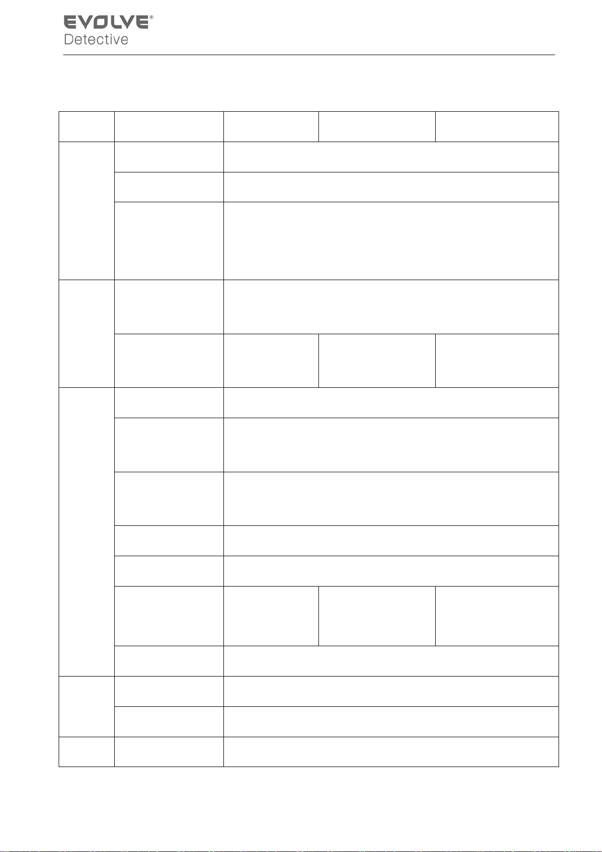
Appendix 4. Technical Specifications
Type 4ch 8ch 16ch
System
Interface
Main processor
Operation system Embedded LINUX operation system
System resource synchronous multi-channel recording, synchronous multi-channel
sub-code stream, synchronous multi-channel playback, synchronous
Operation interface 16 bit true color graphical menu interface, mouse operation
display 1/4image display 1/4/8/9 image display 1/4/8/9/16 image
Video standard
Surveillance image
High performance embedded microprocessor
network operation
supportive
display
P AL 625line,50 f/s; NTSC 525 line,60 f/s
P AL, D1(704x576);NTSC, D1(704x480)
Video
Audio
quality
Playback image
quality
Video compression H.264 mp
Video control 6 options
Recording speed 100/120fps (D1) 200/240fps(CIF),
Motion detect 64(8×8) detection areas, multiple sensitivity
Audio compression G711A
Bidrectional Talk Support
P AL,D1(704×576);NTSC, D1(704*480)
400/480fps CIF
50/60fps D1
Record
Recording mode manual >alarm>motion detect>timing
- 60 -
Page 65
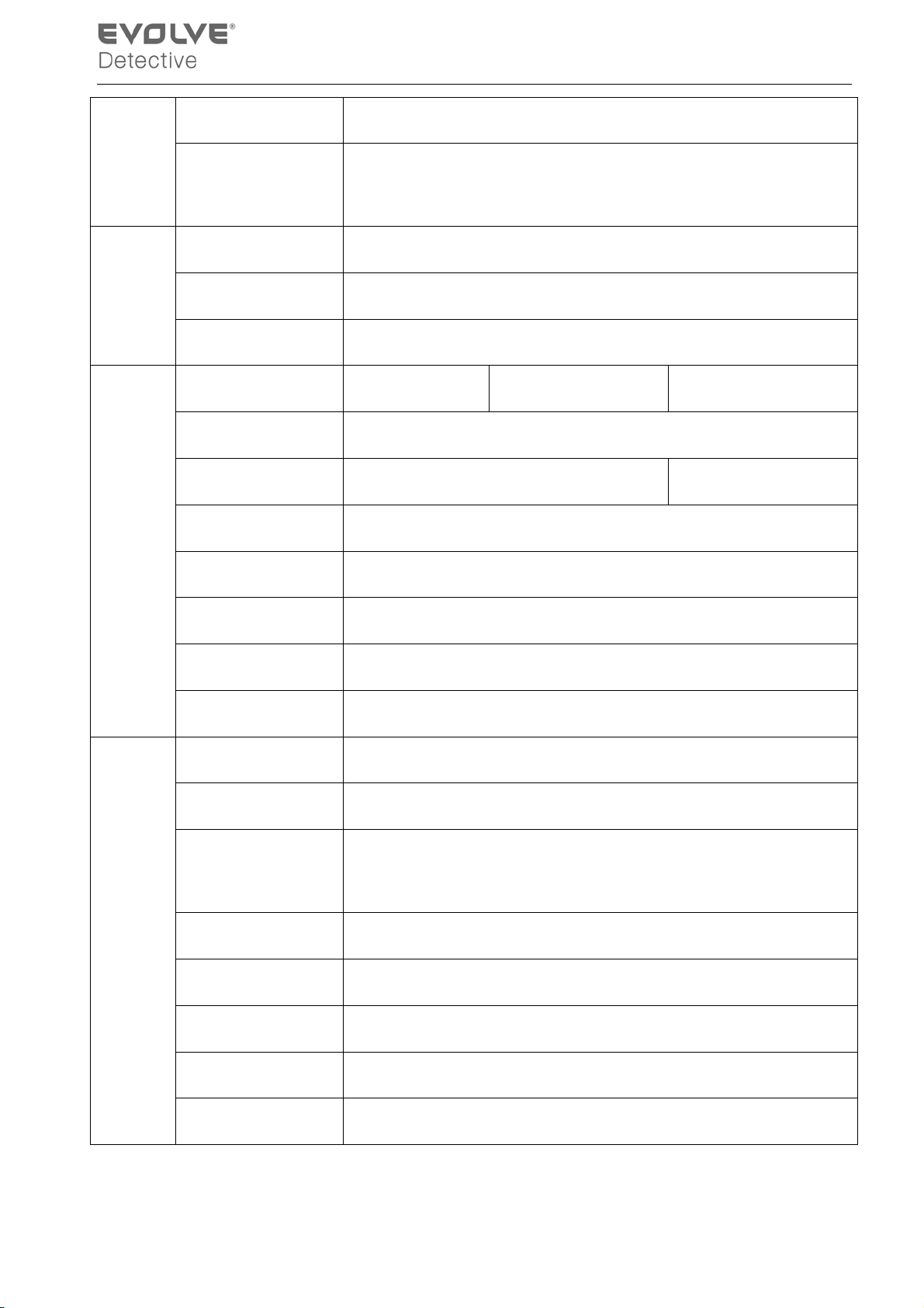
And
Playback
Storage
And
backup
Port
Playback Any channels playback, multiple channels playback
Search mode Time searching, calendar searching, affair searching, channel
searching, information searching
Space Occupation
Audio: 28.8MB/H Video:25~450MB/H
Recording storage Hard disk, network
Backup mode Network, USB flash , USB movable HDD,USB DVD-RW
Video input 4 BNC 8 BNC 16 BNC
Video output 1 BNC, 1 VGA
Audio input 4 RCA 1 RCA
Audio output 1 RCA
Network port RJ45 10M/100M
Other
PTZ control port 1 RS485
USB port 2* USB2.0 ports
Hard disk port 1 SATA port
Power supply 12V/2A external power supply
Power consumption <15W (without hard disk)
Working
0 ℃~+55 ℃
temperature
Working humidity
Air pressure
10%-90%
86kpa-106kpa
Size 260*200*43mm
Weight
2kg(without hard disk)
Installation Desktop
- 61 -
 Loading...