

Page 1

®
P O W E R T O O L S
www.evolutionrage.com
255mm (10”) TCT
Multi Purpose
Sliding Mitre S.A.W.
www.evolutionrage.com
Instruction
Manual
Manuel d’Instruction
Instruktionshandbuch
Manual de Instrucción
Handleiding
P O W E R T O O L S
Read instructions before operating this tool.
®
Lisez le mode d’emploi avant d’utiliser cet outil.
Vor Benutzung des Werkzuegs bitte bedienungsanleitungen
sorgfaltig lesen.
Antes de utilizar esta herramienta, lean las instrucciones.
Lees instructies alvorens dit hulpmiddel in werking te stellen.
®
BUILD
Page 2
Important
Please read these operating and safety instructions carefully and
completely. For your own safety, before using this equipment
check that the voltage is correct and that all handles and parts are
rmly secured. If you are uncertain about any aspect of using this
equipment, please contact our Technical Helpline.
Technical Helpline UK: 0870 609 2297
Technical Helpline USA: 1-866-EVO-TOOL
warranty – written or verbal – for saw blades. In no event shall
Evolution Power Tools be liable for loss or damage resulting directly
or indirectly from the use or merchandise or from any other cause.
Evolution Power Tools is not liable for any costs incurred on such
goods or consequential damages. No ofcer, employee or agent of
Evolution Power Tools is authorised to make oral representations of
tness or to waive any of the foregoing terms of sale and none shall
be binding on Evolution Power Tools.
Questions relating to this limited warranty should be directed to the
company’s head ofce, or call the appropriate Helpline number.
Rage 3 Multi Purpose Sliding Mitre Saw
Congratulations on your purchase of an Evolution Power
Tools Rage 3 Sliding Mitre Saw. Please complete and mail
your product registration card. Doing so will validate your
machine’s warranty period and ensure prompt service if
needed. We sincerely thank you for selecting a product
from Evolution Power Tools.
CAUTION: IMPORTANT
SAFETY INSTRUCTIONS
To reduce the risk of electric shock, this equipment is tted
with an approved cord and plug for its intended Country of
use. Do not change the plug in any way.
GENERAL SAFETY RULES
WARNING: For Your Own Safety. Read Instruction Manual Before
Operating Mitre Saw.
1. KEEP GUARDS IN PLACE and in working order.
2. REMOVE ADJUSTING KEYS AND WRENCHES. Form habit of
checking to see that keys and adjusting wrenches are removed from
tool before turning it on.
3. KEEP WORK AREA CLEAN. Cluttered areas and benches invite
accidents.
4. DON’T USE IN DANGEROUS ENVIRONMENT. Don’t use power
tools in damp or wet locations, or expose them to rain. Keep work
area well lit.
5. KEEP CHILDREN AWAY. All visitors should be kept a safe
distance from work area.
6. DON’T FORCE TOOL. It will do the job better and safer at the
rate for which it was designed.
7. USE PROPER EXTENSION CORD. Make sure your extension
cord is in good condition. When using an extension cord, be sure to
use one heavy enough to carry the current your product will draw. An
undersized cord will cause a drop in line voltage resulting in loss of
power and overheating.
8. WEAR PROPER APPAREL. Do not wear loose clothing, gloves,
neckties, rings, bracelets, or other jewellery which may get caught in
moving parts. Nonslip footwear recommended. Wear protective hair
covering to contain long hair.
9. ALWAYS USE SAFETY GLASSES. Also use face or dust mask if
cutting operation is dusty. Everyday eyeglasses only have impact
resistant lenses, they are NOT safety glasses.
10. SECURE WORK. Use clamps to hold work when practical. It’s safer
than using your hand and it frees both hands to operate tool.
11. DON’T OVERREACH. Keep proper footing and balance at all
times.
12. MAINTAIN TOOLS WITH CARE. Keep tools sharp and clean for
best and safest performance. Follow instructions for lubricating and
changing accessories.
13. DISCONNECT TOOLS before servicing and when changing
accessories, such as blades.
14. REDUCE THE RISK OF UNINTENTIONAL STARTING. Make sure
switch is in off position before plugging in.
15. USE RECOMMENDED ACCESSORIES. Only use genuine Evolution
accessories.
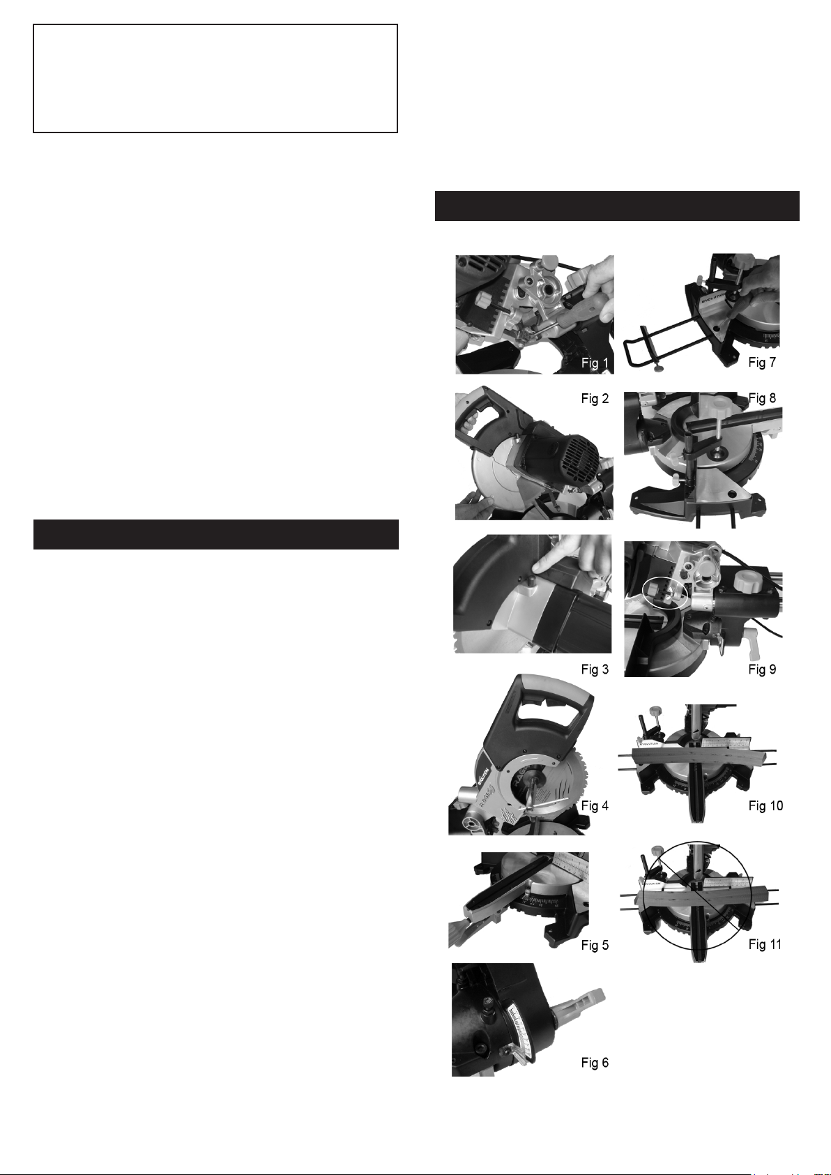
FIGURE ILLUSTRATIONS
2 9
Page 3

20°
25°
30°
35°
40°
45°
50°
55°
60°
65°
70°
75°
80°
85°
90°
M- 43.22°
B- 14.00°
M- 42.19°
B- 17.39°
M- 40.89°
B- 20.70°
M- 39.32°
B- 23.93°
M- 37.45°
B- 27.03°
M- 35.26°
B- 30.00°
M- 32.73°
B- 32.80
M- 29.84°
B- 35.40°
M- 26.57°
B- 37.76°
M- 22.91°
B- 39.86°
M- 18.88°
B- 41.64°
M- 14.51°
B- 43.08°
M- 9.85°
B- 44.14°
M- 4.98°
B- 44.78°
M- 0.00°
B- 45.00°
M- 34.32°
B- 11.60°
M- 33.36°
B- 14.38°
M- 32.18°
B- 17.09°
M- 30.76°
B- 19.70°
M- 29.10°
B- 22.20°
M- 27.19°
B- 24.56°
M- 25.03°
B- 26.76°
M- 22.62°
B- 28.78°
M- 19.96°
B- 30.60°
M- 17.07°
B- 32.19°
M- 13.95°
B- 33.53°
M- 10.65°
B- 34.59°
M- 7.19°
B- 35.37°
M- 3.62°
B- 35.84°
M- 0.00°
B- 36.00°
M- 28.48°
B- 9.85°
M- 27.62°
B- 12.20°
M- 26.57°
B- 14.48°
M- 25.31°
B- 16.67°
M- 23.86°
B- 18.75°
M- 22.21°
B- 20.70°
M- 20.36°
B- 22.52°
M- 18.32°
B- 24.18°
M- 16.10°
B- 25.66°
M- 13.71°
B- 26.95°
M- 11.17°
B- 28.02°
M- 8.50°
B- 28.88°
M- 5.73°
B- 29.50°
M- 2.88°
B- 29.87°
M- 0.00°
B- 30.00°
M- 24.35°
B- 8.53°
M- 23.56°
B- 10.57°
M- 22.64°
B- 12.53°
M- 21.53°
B- 14.41°
M- 20.25°
B- 16.19°
M- 18.80°
B- 17.87°
M- 17.20°
B- 19.41°
M- 15.44°
B- 20.82°
M- 13.54°
B- 22.07°
M- 11.50°
B- 23.16°
M- 9.35°
B- 24.06°
M- 7.10°
B- 24.78°
M- 4.78°
B- 25.30°
M- 2.40°
B- 25.61°
M- 0.00°
B- 25.71°
MAINTENANCE
M- 21.27°
B- 7.52°
M- 20.58°
B- 9.31°
M- 19.73°
B- 11.03°
M- 18.74°
B- 12.68°
M- 17.60°
B- 14.24°
M- 16.32°
B- 15.70°
M- 14.91°
B- 17.05°
M- 13.36°
B- 18.27°
M- 11.70°
B- 19.35°
M- 9.93°
B- 20.29°
M- 8.06°
B- 21.08°
M- 6.12°
B- 21.69°
M- 4.11°
B- 22.14°
M- 2.07°
B- 22.41°
M- 0.00°
B- 22.50°
M- 18.88°
B- 6.72°
M- 18.26°
B- 8.31°
M- 17.50°
B- 9.85°
M- 16.60°
B- 11.31°
M- 15.58°
B- 12.70°
M- 14.43°
B- 14.00°
M- 13.17°
B- 15.19°
M- 11.79°
B- 16.27°
M- 10.31°
B- 17.23°
M- 8.74°
B- 18.06°
M- 7.10°
B- 18.75°
M- 5.38°
B- 19.29°
M- 3.62°
B- 19.68°
M- 1.82°
B- 19.92°
M- 0.00°
B- 20.00°
M- 16.98°
B- 6.07°
M- 16.41°
B- 7.50°
M- 15.72°
B- 8.89°
M- 14.90°
B- 10.21°
M- 13.98°
B- 11.46°
M- 12.94°
B- 12.62°
M- 11.80°
B- 13.69°
M- 10.56°
B- 14.66°
M- 9.23°
B- 15.52°
M- 7.82°
B- 16.26°
M- 6.34°
B- 16.88°
M- 4.81°
B- 17.37°
M- 3.23°
B- 17.72°
M- 1.62°
B- 17.93°
M- 0.00°
B- 18.00°
EC Declaration of Conformity
We: Evolution Power Tools Limited
Evolution House
New Street
Shefeld
S20 3GH
As the supplier of the item listed below:-
Rage 3 255mm (10”) TCT Multi Purpose Sliding Mitre Saw
Part No. RAGE3255
Voltage 110 - 230V
Power 2000W
Declare, under our sole responsibility that the equipment to which
this document relates is in conformity with the following standards
or other normative documents:-
EN 60335-1:1994+A1+A2+A11–A16
EN 55014-1:2000+A1+A2
EN 55014-2:1997+A1
EN 61000-3-2:2000
EN 61000-3-3:1995+A1
EN 61000-3-11:2000
CLEANING
Use only mild soap and damp cloth to clean the tool.
Never let any liquid get inside the tool; never immerse
any part of the tool into a liquid.
Regularly clean the tool’s air vents with compressed dry air.
DO NOT ATTEMPT TO CLEAN BY INSERTING POINTED
OBJECTS THROUGH OPENINGS.
LUBRICATION
All of the bearings in this tool are lubricated with a
sufcient amount of high grade lubricant for the life of
the unit under normal operating conditions. Therefore,
no further lubrication is required.
12 MONTHS WARRANTY
12 MONTH LIMITED WARRANTY. EVOLUTION POWER TOOLS
RESERVES THE RIGHT TO MAKE IMPROVEMENTS AND
MODIFICATIONS TO DESIGN WITHOUT PRIOR NOTICE.
Evolution Power Tools will, within twelve (12) months from the
original date of purchase, repair or replace any goods found to
be defective in materials or workmanship, provided the product
warranty registration card has been returned to Evolution Power
Tools within thirty (30) days of purchase date. This warranty is void
if the tool being returned has been used to cut materials beyond the
recommendations in the Instruction Manual or if the saw has been
damaged by accident, neglect, or improper service. This warranty
does not apply to machines and / or components which have been
altered, changed, or modied in any way, or subjected to use beyond
recommended capacities and specications. Electrical components
are subject to respective manufacturers’ warranties. All goods
returned defective shall be returned prepaid freight to Evolution
Power Tools. Evolution Power Tools reserves the right to optionally
repair or replace it with the same or equivalent item. There is no
And thereby conforms to the protection requirements of
Council Directive 73/23/EC amended by 93/68/EC relating
to the Low Voltage Directive, Council Directive 98/37/EC
relating to the Machinery Directive and Council Directive
89/336/EC relating to the EMC Directive, and is compliant
with EU Directive 2002/95/EC in relation to the Restriction of
Hazardous Substances in Electrical & Electronic Equipment
(ROHS).
Guaranteed Sound Power Level: 98 dB(A)
Conformity assessment method to annex V of Directive
2000/14/EC
Relevant technical documentation kept at Evolution Power
Tools Ltd, Shefeld
Authorised by:
Mr M J Gavins
Managing Director
19th June 2006
06
(Year of afxation)
8 3
Page 4

16. NEVER STAND ON TOOL. Serious injury could occur if the tool is
tipped or if the cutting tool is unintentionally contacted.
17. CHECK DAMAGED PARTS. Before further use of the tool, a guard or
other part that is damaged should be carefully checked to determine
that it will operate properly and perform its intended function – check
for alignment of moving parts, binding of moving parts, breakage of
parts, mounting, and any other conditions that may affect its operation.
A guard or other part that is damaged should be properly repaired or
replaced.
18. Wear eye protection.
19. Keep hands out of path of saw blade.
20. Do not operate saw without guards in place.
21. Never reach around saw blade.
22. Turn off tool and wait for saw blade to stop before moving workpiece
or changing settings.
23. Disconnect power before changing blade, servicing or cleaning.
24. To reduce the risk of injury, return carriage to the full rear position after
each crosscut operation.
SAVE THESE INSTRUCTIONS
FOR FUTURE REFERENCE
ADDITIONAL SAFETY INSTRUCTION
1. Although compact, this saw is heavy. To reduce the risk of back injury,
get help whenever you have to lift the saw.
2. To reduce the risk of back injury, hold the tool close to your body when
lifting. Bending your knees so you can lift with your legs, not your
back. Lift by using the handhold areas at each side of the bottom of
the base.
3. Never carry the mitre saw by the power cord or the trigger grip of the
handle. Carrying the tool by the power cord could cause damage to
the insulation or the wire connections resulting in electric shock or
re.
4. Before removing the saw from the carton tighten the slide lock knob
to guard against sudden movement.
5. Place the saw on a secure stationary work surface and check the saw
over carefully.
6. Warning. Do not stare directly at the laser beam. A hazard may exist
if you deliberately stare into the beam, please observe all safety rules
as follows.
- The laser shall be used and maintained in accordance with the
manufacturer instructions.
- The laser beam shall not be deliberately aimed at personnel
and shall be prevented from being directed towards the eyes of a
person.
- Always ensure the laser beam is aimed at the workpiece
without reective surfaces, i.e. wood or rough coated surfaces are
acceptable.
- Do not change the laser light assembly with a different type.
SPECIFICATIONS
Model Rage 3
Motor (230v-240v ~ or 110v ~ 50/60 Hz) (Watts): 2000
RPM No Load (min-1): 2500
Recommended Maximum Duty Cycle (Minutes): 30
Sound Pressure Level (Under Load) (dB(A)): 98
Vibration Level (Under Load) (m/s2): 1.98
Weight: 19.6Kg
Blade Dimensions
Maximum Diameter: (10”) 255mm
Bore Diameter: (1”) 25.4mm
Thickness: (1/16”) 2mm
Maximum Cutting Capacity
Mitre Bevel Max Width of Cut Max Depth of Cut
90º 90° 300mm (11.81””) 75mm (2.95”)
45°L / 45°R 45° 210mm (8.26””) 40mm (1.57”)
45°L / 45°R 90° 210mm (8.26””) 75mm (2.95”)
90° 45° 300mm (11.81””) 40mm (1.57”)
5. Turn on saw and allow the saw to reach full speed.
6. Press the lower guard unlock lever for saw head release.
7. Push the saw handle down and cut the workpiece.
8. After cut is complete turn off saw, allow blade to completely stop.
WARNING: For your convenient use, the saw has a blade brake. Never
rely on it to replace proper use of the guard on your saw.
BODY AND HAND POSITION
1. Never place hands near cutting area and keep hand away from the
path of blade.
2. Hold workpiece rmly to the fence to prevent movement toward the
blade.
3. Before making a cut. Make a dry run with the power off so you can
see the path of the blade.
5. Keep hands in position until trigger has been released and the blade
has completely stopped.
MITRE CUT
An angle of up to 45° left or right can be obtained using the unit.
1. Loosen the mitre angle lock.
2. Pull up the mitre angle set lever.
3. Turn the table unit to the desired angle is indicated on the mitre angle
pointer.
4. Tighten the angle lock knob to hold the desired angle.
5. Start the saw and allow it to reach full speed before commencing the
cut.
BEVEL CUT
1. Loosen the bevel angle lock.
2. Move the blade to desired bevel angle.
3. Stand to the left side of the handle to make the cut.
COMPOUND CUT
When a compound cut is required. Select the desired bevel and mitre
positions.
CUTTING BOWED MATERIAL (Fig 10 & 11)
Before cutting a workpiece, check to make sure it is not
bowed. If it is bowed, the workpiece must be positioned
and cut as illustrated. Do not position workpiece
incorrectly or try to cut the workpiece without the
support of the fence. This will cause pinching of the
workpiece on the blade. The workpiece could suddenly
jump or move and your hand could hit the blade.
CUTTING COMPOUND MITRES
To aid in making the correct settings, the compound
angle setting chart below has been provided. Since
compound cuts are the most difcult to accurately
obtain, trial cuts should be made in scrap material, and
much thought and planning made, prior to making your
required cut.
WARNING: Always unplug the tool before making any
assembly, adjustments or changing accessories.
COMPOUND ANGLE SETTINGS FOR POPULAR STRUCTURES
Each B (Bevel) and M (Mitre) Setting is given to the closest 0.005°
PITCH
OF
SIDE
0°
5°
10°
15°
4 5 6 7 8 9 10
M- 45.00°
B- 0.00°
M- 44.89°
B- 3.53°
M- 44.56°
B- 7.05°
M- 44.01°
B- 10.55°
N U M B E R O F S I D E S
M- 36.00°
B- 0.00°
M- 35.90°
B- 2.94°
M- 35.58°
B- 5.86°
M- 35.06°
B- 8.75°
M- 30.00°
B- 0.00°
M- 29.91°
B- 2.50°
M- 29.62°
B- 4.98°
M- 29.15°
B- 7.44°
M- 25.71°
B- 0.00°
M- 25.63°
B- 2.17°
M- 25.37°
B- 4.32°
M- 24.95°
B- 6.95°
M- 22.50°
B- 0.00°
M- 22.42°
B- 1.91°
M- 22.19°
B- 3.81°
M- 21.81°
B- 5.68°
M- 20.00°
B- 0.00°
M- 19.93°
B- 1.71°
M- 19.72°
B- 3.40°
M- 19.37°
B- 5.08°
M- 18.00°
B- 0.00°
M- 17.94°
B- 1.54°
M- 17.74°
B- 3.08°
M- 17.42°
B- 4.59°
4 7
Page 5

DEPTH STOP (Fig. 9)
Use of the depth stop feature means that the blade will not cut completely
through the workpiece depending on the depth that it is set to. This allows
the operator to cut slots in the workpiece. NOTE: It is advisable that the
depth of cut is checked using a scrap piece of timber prior to undertaking
the workpiece. By making a cut in the workpiece and then slightly moving
the workpiece to the left or right before repeating, it is possible to perform
trenching cuts in the workpiece.
To use the depth stop feature follow these steps:
1. Loosen the wing nut.
2. Adjust the thumb knob to the required depth.
3. Once set to the desired depth, tighten the wing nut against the
retaining bracket to lock the depth stop and ensure that there is no
movement.
Standard Equipment Supplied With Unit: 1 MultiBlade, 1 Box Spanner, 1
Operating Instructions.
ASSEMBLY
MOUNTING THE MITRE SAW
WARNING: To reduce the risk of injury from unexpected saw movement,
place the saw in the desired location either on a workbench or other
recommended leg set. The base of the saw has four holes to mount the
mitre saw. If the saw is to be used in one location, permanently fasten it to
the workbench or leg set.
CLEARING JAMMED MATERIAL:
1. Turn mitre saw “OFF” by releasing trigger switch.
2. Wait for all moving parts to stop.
3. Unplug the mitre saw.
4. Remove jammed material from the unit.
OPERATING INSTRUCTION
DISCONNECT THE MITRE SAW AND INSPECT YOUR
SAW BEFORE EACH USE.
WARNING: To reduce the risk of injury, always unplug the saw before
changing or adjusting anything. Compare the direction of rotation arrow on
the guard to direction arrow on the blade. The blade teeth should always
point downward at the front of the saw. Tighten the arbor screw. Tighten
the cover plate screw.
PREPARING TO MAKE THE CUT
CAUTION: NEVER pull the saw toward you during a cut. The blade can
suddenly climb up on top of the workpiece and force itself toward you.
- Avoid awkward operations and hand positions where a sudden slip
could cause ngers or hand to move into the blade.
- Cut only one workpiece at a time.
- Clear everything except the workpiece and related support devices
away from the blade before turning the mitre saw on.
- Secure workpiece using clamps to hold the workpiece securely.
MAKING COMMON SLIDE COMPOUND CUTS
There are two types of cuts that can be made with the slide compound
mitre saw.
Slide Cutting
Loosen the side lock knob and move the cutting head towards the operator.
The saw blade is lowered into the workpiece and then pushed to the rear of
the saw to complete the cut. Used for cutting wide pieces. It should not be
used for cutting metal materials.
1. Put wood against fence and secure with clamp as appropriate.
2. Loosen the slide lock knob.
3. Grasp the saw handle and pull the carriage until the arbor (centre of
saw blade) is over the front edge of the workpiece.
4. Press the lower guard unlock lever for saw head release.
5. Switch on the saw and allow the saw to reach full speed.
6. Push the saw handle all the way down and cut through the leading
edge of the workpiece.
7. Gently push the saw handle towards the fence completing the cut.
8. Push power head to full rear position after each cut.
9. Release the trigger to switch off the saw and allow blade to come to
a complete stop before moving hands or remove the workpiece.
CHOP CUTTING
The slide lock knob is tightened and the saw handle is pushed down to cut
through the workpiece. This type of cut is used mainly for narrow pieces
and all metals.
1. Slide the cutting head to the rear as far as it will go.
2. Lock slide lock knob.
3. Place the workpiece on table and against fence and secure with
clamp as appropriate.
4. Grasp the saw handle.
1. Tighten the sliding rail, mitre and bevel locks.
2. Place the saw so other people cannot stand behind it. Thrown debris
could injure people in its path.
3. Place the saw on a rm, level surface where there is plenty of room
for handing and properly supporting the workpiece.
4. Support the saw so the table is level and the saw does not rock.
5. Bolt or clamp the saw to its support.
INSTALLING OR REMOVING THE BLADE
WARNING: Only use genuine Evolution blades which are designed for
this machine.
1. Ensure cutting head is up.
2. Remove the guard screw. (Fig. 1)
3. Press safety lock button in and lift up the lower blade guard. (Fig. 2)
4. Press the black lock button to lock the arbor. (Fig. 3)
5. Using the supplied spanner, release the arbor screw to remove the
blade. (Fig. 4)
6. Install the new 255 mm (10”) blade. Make sure the rotation arrow on
the blade matches the clockwise rotation arrow on the upper guard.
The blade teeth should always point downward at the front of the
saw.
7. Install the blade washer and arbor screw.
8. Turn box spanner to secure the blade.
9. Tighten arbor screw using moderate force, but do not overtighten.
10. Replace the guard screw. (Fig. 1)
ADJUSTMENT OF THE CUTTING ANGLES.
MITRE ANGLE: (Fig. 5)
1. Loosen the sliding rail locking knob, push the saw handle back
as far as it will go and lock the handle.
2. Loosen the mitre angle lock knob.
3. Pull up the angle set lever and turn the table until the angle pointer
reach to the desired angle on angle mitre guide (g 5).
4. Tighten the mitre angle lock knob.
BEVEL ANGLE: (Fig. 6)
1. Lock the cutting head down with the cutting lock knob.
2. Loosen the bevel lock.
3. Adjust angle until the bevel angle point reaches the desired bevel
angle.
4. Tighten the bevel lock.
FITTING THE REPEAT STOP
1. Loosen the thumb screw to allow the arms of the workpiece
supports into the holes in the repeat stops.
2. Tighten the thumb screws rmly to minimize movement on the
workpiece support.
3. Attach the workpiece support as detailed below.
NOTE: By loosening the thumb screws the repeat stop can be
adjusted to required widths for each application.
FITTING THE WORKPIECE SUPPORT (Fig.7)
1. Loosen the support retaining screw located on the turntable.
2. Insert the workpiece support into the retaining holes in the base.
3. Tighten the retaining screw.
FITTING THE WORKPIECE CLAMP (Fig.8)
1. Fit the clamp to the retaining hole that best suits the cutting
application, ensuring that it is fully pushed down.
2. Tighten the thumbscrew to lock the pillar.
3. Put the workpiece to be cut onto the saw bed.
4. Adjust the clamp so that it securely holds the workpiece.
6 5
Page 6

REV. 1.00
91
98
29
4
149
149
30
31
28
151
152
10
10
32
113
113
66
48
46
61
65
55
44
80
79
78
81
76
74
75
74
59
4
3
61
67
68
67
68
64
70
71
61
60
3
59
4
3
59
55
4
73
16
49
72
49
63
69
64
63
61
60
113
4
4
4
112
102
145
145
146
147
148
32
141
140
146
147
148
150
10
10
143
144
142
32
141
140
139
138
137
132
133
134
131
130
129
128
4
127
126
110
109
108
107
106
105
104
123
122
121
101
100
99
97
96
95
94
93
88
118
119
120
114
116
117
116
115
114
87
86
84
83
82
3
58
57
56
52
54
53
50
49
4
47
4
45
43
40
42
41
41
40
39
39
40
27
27
40
39
38
27
37
36
35
34
4
24
25
16
16
16
16
18
16
19
17
16
16
15
23
21
22
16
20
14
12
8
9
1
1
2
2
2
575
6
11
10
51
4
4
136
33
29
62
103
125
124
4
4
4
13
3
4
4
3
4
3
77
92
135
27
27
26
89
90
111
RAGE 3
D u a l R a i l S l i d e M i t r e S a w
®
S e r v i c e P a r t s L i s t
 Loading...