

Evolution E1F10135PHR, GT10150PHR, E1C12150PHR, E1C13150PHR, E1T12150PHR Operating Instructions Manual
...Page 1
Model
Serial No.
Engine No.
Year of Manufacture
CE
Operating
Instructions
793-1202
Unit 8, Hudson Road
Saxby Road Ind. Est.
Melton Mowbray
Leicestershire LE13 1BS
Telephone: +44 (0)1664 567226 Fax: +44 (0)1664 410127
E-mail: info@dualpumps.co.uk www.dualpumps.co.uk
pumps
pumps
Evolution
v
pressure washers
Page 2
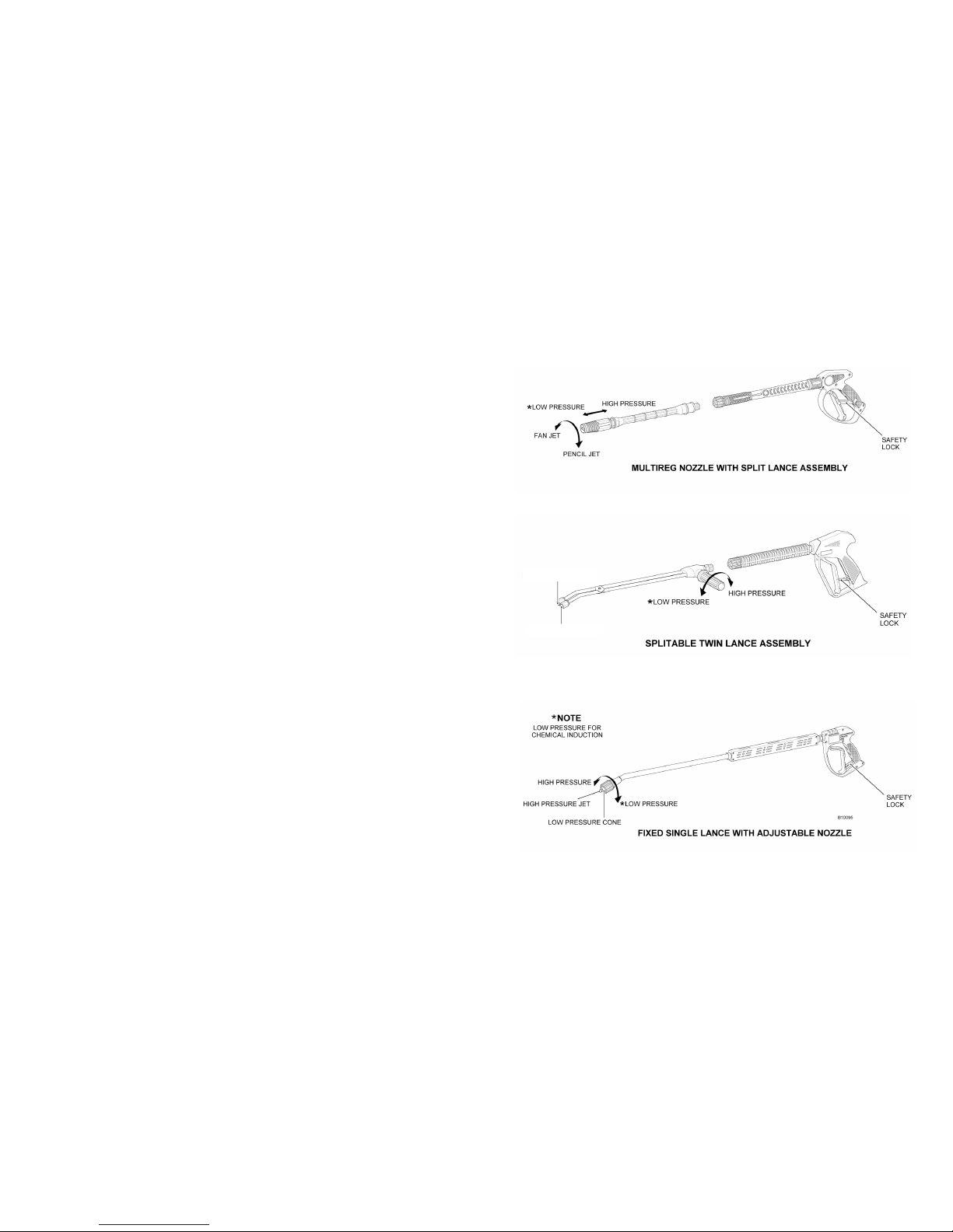
Appendix 1. Lance variations
LOW PRESSURE JET
HIGH PRESSURE JET
Page 3

purchaser, (six (6) months for the equipment on hire or rental). There is no implied
warranty of tness for a particular purpose or merchantability when this product
is put to rental use.
No person including any dealer or representative of Dual Pumps Ltd is authorised
to make any representation or warranty concerning Dual Pumps Ltd products
on behalf of Dual Pumps Ltd, or to assume for Dual Pumps Ltd the obligations
contained in this warranty. Dual Pumps Ltd reserves the right to make changes in
design and other changes and improvements upon its products without imposing
any obligation on itself to install the same, in its existing products or products then
in process or manufacture.
This warranty does not affect any statutory rights that you may have.
Procedure for claiming under this warranty
The claimant must despatch the unit, product or part at his own expense to the
Dual Pumps Ltd factory with a full detailed report for inspection, upon receipt
Dual Pumps Ltd will inspect and decide whether the unit, product or part is in
fact a genuine warranty claim. Upon this decision the pump, product or part will
be replaced either free of charge under this warranty or despatched and charged
to the original customer together with a full report should it be found not to be
covered by this warranty.
Warranty claimed items, if required urgently will be despatched to the customer
and charged for, on receipt of the claimed defective item Dual Pumps Ltd will
decide whether the claim is valid and if so will issue a credit for the item. Should
Dual Pumps Ltd nd the claimed item to be out of warranty declarations the said
charge will stand and be paid by the customer as normal.
The copyright of this manual belongs to Dual Pumps Ltd and must not be copied
or reproduced without the express permission of the company.
Pressure Washer
Operating Instructions
This manual and any other literature supplied should be read
thoroughly before attempting to operate the Power Washer. Pay
particular attention to any instructions relating to safety, and the
starting, stopping and maintenance of petrol and diesel engines.
This manual has been compiled to give all of the necessary information
to operate the Dual Pumps range of Pressure Washers safely and
effectively. It is recommended the manual and its accompanying
literature be read and understood before attempting to assemble
or operate the equipment. Following these simple instructions will
ensure operator safety and prolong the life of the power washer.
Our policy is to improve our products continuously and we therefore
reserve the right to discontinue or change specications, models or
designs without notice or obligation.
THESE INSTRUCTIONS SHOULD BE KEPT
WITH THE MACHINE AT ALL TIMES.
Page 4

2. Equipment Variants and Options
This equipment has been designed and manufactured for the high pressure
washing of machinery, buildings etc, using water and detergent. Use only a
recommended detergent.
It should not be used for washing electrical equipment, people, animals and
surfaces that are loose and easily damaged.
This manual deals with the following variants of pressure washers,
Power input Petrol and diesel engines.
4bhp – 18bhp
High-pressure Multi cylinder plunger
Pump 10 lpm – 30 lpm
100 bar – 400 bar pump pressure.
Transport frame Rigid steel frames in either static or
wheeled options.
EC DECLARATION OF CONFORMITY
Dual Pumps Ltd
Unit 8, Hudson Road
Saxby Road Ind. Est.
Melton Mowbray
Leicestershire LE13 1BS
Declares that this equipment conforms to the following directives,
2000/14/EC, 2006/42/EC, 2004/108/EEC
Tom Herridge
Technical Manager
1. Index
Equipment Variants and Options .........................................................section 2
Safety ..................................................................................................section 3
Description of Main Features...............................................................section 4
Installation ..........................................................................................section 5
Operation .............................................................................................section 6
Maintenance ........................................................................................section 7
Storage ................................................................................................section 8
Fault Finding ........................................................................................section 9
Warranty ............................................................................................section 10
Lance Variations .............................................................................. appendix 1
10. Warranty
Limited Warranty Supplied by Dual Pumps Ltd
Dual Pumps Ltd as suppliers warrants to the original purchaser, each new unit
or other product supplied from its factory, for the period of twelve (12) months
from the date of shipment from the factory, six (6) months for equipment on hire
or rental), to be free from defects in material and workmanship under normal use
and service. “Normal Use and Service” means not to exceed recommendations on
maximum speeds, pressures and temperatures or handling uids not compatible
materials, as noted in the applicable Dual Pumps catalogue, technical literature
and instructions. This warranty shall not apply to any pump or other product, which
has been repaired or altered, to adversely affect the performance or reliability of
the pump or product. Lance or hoses are not covered by this warranty due to the
adverse conditions of their use.
Neither this warranty nor any implied warranty apply to damage caused by any
of the following:
1. Freight damage
2. Frost or freezing damage
3. Damage caused by parts and/or accessories or components not obtained
from or approved by Dual Pumps Ltd.
4. Any consequential or incidental damage arising from the use of any, pump or
other products supplied by Dual Pumps Ltd.
5. Damage due to misapplication and/or misuse. The normal wear of moving
parts or components affected by moving parts.
The liability of Dual Pumps Ltd under the foregoing warranty is limited to the repair
or replacement at Dual Pumps Ltd option without charge for labour, mileage costs
or materials of any parts upon return of the entire pump or other product or of
the particular part to the Dual Pumps Ltd factory within the warranty period at the
sole expense of the purchaser, which part shall upon examination appear to Dual
Pumps Ltd satisfaction to have been defective in material or workmanship.
The liability of Dual Pumps Ltd under any theory or recovery (except any express
warranty where the remedy is set forth in the above paragraph) for loss, harm or
damage, shall be limited to the lesser of the actual cost, harm or damage, or the
purchase price of the involved pump or other product when sold by Dual Pumps
Ltd to its customer. Dual Pumps Ltd expressly warrants its pumps or other products
as above stated.
There are no other express warranties. Any implied warranties, including implied
warranty of merchantability or of tness for a particular purpose, are limited in
duration to twelve (12) months from the date of the purchase by the original
Page 5

9. Fault Finding
Symptom Possible Cause Remedy
Pump running normally Lance in low pressure mode Check and adjust
but pressure low. Pressure Regulator valve Check and adjust
Pump sucking air. Check water supply and
possible air ingress.
Nozzle badly worn Check and/or replace
Worn piston packing Seek professional advice
Fluctuating pressure Blocked water lter Check lter, clean or
replace if necessary.
Pump sucking air Check integrity of suction
hose and connections.
Pressure low after a long Nozzle badly worn Check and/or replace
period of normal use.
Pump noisy. Pump sucking air Check integrity of suction
hose and connections.
Excessive temperature of Reduce temperature to
liquid in pump below 60ºC, do not allow
pump to idle for long
periods.
Worn bearing or valves Seek professional advice
Presence of water in oil. Ingress through breathers Replace oil, do not wash
engine or pump
Worn oil seals Seek professional advice
Water dripping from under pump. Worn piston packing Seek professional advice
Oil dripping from Worn oil seal Seek professional advice
pump/gearbox/engine.
Excessive vibration in Water supply low Check adequacy of water
lance/delivery line. supply. Ensure suction
lter is below water level.
Ingress of air into suction Check integrity of suction
line hose and connections.
Irregular functioning of Seek professional advice
valves
Variants and Options (g 1)
SPL = Sound Power Level on equipment representative for this type.
GSPL = Guaranteed Sound Power Level for this equipment.
Part No. Engine Lpm Bar Kg L x W x H
SPL
LwA dB
GSPL
LwA dB
GF10150PHR Petrol GP160 10 150 31 600x450x440 107 111
GF13150PHR Petrol GP200 13 150 31 600x450x440 106 111
GT10150PHR Petrol GP160 10 150 36 940x600x890 107 111
GT13150PHR Petrol GP200 13 150 37 940x600x890 106 111
E1F10135PHR Petrol GX120 10 135 31.2 600x450x440 98 111
E1C12150PHR Petrol GX160 12 150 35.5 600x400x410 107 111
E1C13150PHR Petrol GX200 13 150 36.5 600x400x410 107 111
E1T12150PHR Petrol GX160 12 150 42.8 630x530x810 107 111
E1T13150PHR Petrol GX200 13 150 43.8 630x530x810 107 111
E1T13200PHR Petrol GX240 13 200 59 800x640x840 105 111
E1T15275PHR Petrol GX390 15 275 65.5 800x640x840 107 111
E1T16200PHR Petrol GX340 16 200 65.5 800x640x840 107 111
E1T20200PHR Petrol GX390 20 200 65.5 800x640x840 107 111
E1T13170DYR Diesel L70N 13 170 69 800x640x840 109 115
E2C14150PHR Petrol GX200 14 150 38.5 600x400x410 106 111
E2T14150PHR Petrol GX200 14 150 38 630x530x810 106 111
E2T15200PHR Petrol GX340 15 200 64.5 800x640x840 107 111
E2T15250PHR Petrol GX390 15 250 64.5 800x640x840 107 111
E2T21200PHR Petrol GX390 21 200 64.5 800x640x840 107 111
E2T15150DYR Diesel L70N 15 150 75.5 800x640x840 109 115
E3T15200PHR Petrol GX340 15 200 77 1100x620x700 107 111
E3T15250PHR Petrol GX390 15 250 78.5 1100x620x700 107 111
E3T21200PHR Petrol GX390 21 200 79 1100x620x700 107 111
E3T15400PBE Petrol V-Twin 15 400 113 1100x620x790 108 108
E3T23250PBE Petrol V-Twin 23 250 108.5 1100x620x790 108 108
E3T30200PBE Petrol V-Twin 30 200 108.5 1100x620x790 108 108
E3T15200DYE Diesel L100N 15 200 108.5 1100x620x720 111 11 2
E3T20190DYE Diesel L100N 20 190 109.5 1100x620x720 111 11 2
Page 6

3. Safety
Power washers should only be used by fully trained, competent persons. They
should not be used by untrained or inexperienced users.
Care should be taken when handling the pressure washers as they have uneven
centres of gravity and may topple over when lifted.
3.1 Suitable Persons
Operators should be physically t and free from the inuences of drugs or
alcohol.
Prolonged periods of operation are strenuous and operators should be
encouraged to take regular breaks. If you have any doubts about your tness
to operate this equipment, seek professional advice before proceeding.
3.2 Protective Clothing
Operators and assistants should wear the following Personal Protective
clothing and equipment: -
Waterproof boots with good non-slip soles
Waterproof overalls
Waterproof gloves
*Goggles or full-face protection to at least BS EN166
**Ear Muffs or Ear Plugs to give protection to at least EN352-1. EN352-2
3.3 Use in conned spaces
Diesel and Petrol engines produce fumes and toxic gases, use only in wellventilated spaces.
To prevent the build up of ammable vapours the charging of petrol and
diesel tanks should not be done in conned spaces. Any spillages should
be cleaned up and any absorbent material used should be disposed of in
a proper manner.
3.4 General Safety
Check all hoses and couplings for tightness and damage, loose connections
should be tightened and damaged hoses replaced.
Ensure the workspace is clear and free from obstructions; consideration
should be given to the erection of fences or sheeting to prevent injury to
others.
High-pressure lances react ‘Kick Back’ when the operating trigger is pulled.
Ensure you have a good rm footing and anticipate this reaction.
Extra care should be taken when working at heights, scaffolding should be
in good condition, secure and properly fenced, working from ladders is not
recommended.
The high-pressure stream can be dangerous, do not point the stream directly
at others or submit them to the ne over-spray.
8. Storage
Disconnect pressure hose and lance, draining water from the hose.
Disconnect water feed hose, draining water from the hose.
Wash out detergent hose with clean water, draining water from the hose.
Turn over the engine by hand to expel water from pump.
Ensure the equipment is clean and dry before storage.
The equipment should be stored in a dry and frost proof place.
7. Maintenance
Activity Each/ 3 months 12 months or
First Use or 50 Hours 100 hours
Inspect / top up oil levels
Engine *
Gearbox *
Pump *
Change Oil
Gearbox (EP90 Gear Oil) * *
Pump (SAE30 Pump Oil) * *
(Change engine oil in-line with the engine First 3
manufacturers recommendation), or at - months or *
50hrs only)
Clean water inlet lter *
Inspect and or change, engine/gearbox drive key
Inspect *
Change *
(It is recommended that you consult your dealer (if required)
before performing this item of maintenance)
Inspect high-pressure hose and its connection for *
tightness and damage
Inspect suction hose and its connections for *
tightness and damage
High pressure jet
Inspect *
Change *
Pneumatic tyres *
Check/Inate tyre pressures (0.7bar, 10psi) *
Page 7

6. Operation
6.1 Start engine (Note: Depress the lance trigger to release water pressure
before starting the engine).
Refer to accompanying booklet relating to the type of engine tted.
6.2 Using High Pressure Lance (Note: See Appendix 1 for lance type and operation)
Release the lance safety catch, which is located behind the trigger.
6.2.2 Point the lance downwards and towards the object being cleaned.
6.2.3 Squeeze, the trigger to start the high-pressure jet, proceed to
wash the object. Adjust the working pressure by turning the
pressure regulator knob + or - to suit the application (g 2, item 13).
Never direct the high-pressure stream at the engine or pump as
this could cause irreparable damage.
WARNING: - High-pressure lances react ‘Kick Back’ when the operating
trigger is pulled. Ensure you have a good rm footing and anticipate this
reaction.
6.2.4 Release the trigger to stop the high-pressure jet.
6.3 Washing using detergent
Attach the detergent induction pipe to the power washer,
(g 2, item 1) placing the opposite lter end into the detergent container.
Select the low pressure setting on the lance, (see appendix 1 for details
of your lance) and spray the water/detergent mixture onto the object
being cleaned. Leave the detergent for the period recommended by the
chemical manufacturer allowing it time to work, washing off with clean water.
The volume of detergent used can be controlled by means of the regulator
on the suction valve (see g 2. item 3).
6.4 Switching Off
Release trigger.
Stop drive engine, (refer to additional literature / handbook supplied,
relating to the type of engine tted, remembering to switch off ignition after
use to prevent draining the battery, electric start models only).
Depress the high-pressure lance’s trigger to release the pressure in the
high-pressure hose.
Disconnect water supply.
WARNING: Do not let the pump idle in By-Pass for lengthy periods, if you
intend to break from work for more than 5 minutes, switch the machine off.
Should the machine run for longer period, the temperature of the recirculating water will increase rapidly and could risk damaging the pump
seals. (Models with internal by-pass only).
Running power washers should never be left unattended.
3.5 Control of Vibration at Work Regulations 2005
This machine in its standard form dose not exceed the 2.5 m/s² vibration action
value and should not require any daily limitations to it use. Periodic equipment
checks and servicing will maintain the characteristics and efciency of this
machine.
Warning:
Any modications or accessories added or use with this machine may affect
the vibration levels. Under the Control of Vibration at Work Regulations it
is the employers duty to manage the exposure to vibration and implement
training and health surveillance for employees.
Under the Supply of Machinery (Safety) Regulations1992 (SMSR),
you should ensure equipment is in good condition and maintained in
accordance with the manufacturers instructions, any modications or
accessories added to this machine should be assessed for safe operation
and vibration, then implement appropriate measures.
* Note: Goggles or Full Face Protection.
The wearing of eye and face protection in hazardous areas is a requirement under regulation
4 of the personal protective equipment at work regulations 1992.
Regulation 4 requires employers to provide suitable personal protective equipment to
employees who may be exposed to risks affecting their health and safety.
Full Face Protection.
High speed flying partials or chemical splashes are rarely aimed directly at the eyes. A full
face visor offers the maximum protection in extreme conditions. Full face shields offer a wide
area of protection and because of the all round ventilation, remain mist free even in wide
temperatures swings.
Chemical Splash.
Chemical splashes and vapours can hit you from all sides. It’s important that full eye
enclosure is selected, e.g. Unvented goggles. Full face shields will also protect the whole
face from liquid splashes. Those with chin guards should be selected where there is a
danger of splash deflecting up from work surfaces.
Impact.
Impact hazards are caused by fast moving particles from the cleaning operation. The
potential impact speed must be assessed before selecting the most appropriate protection.
Safety glasses could be dislodged by high velocity impacts, in which case goggles or face
shield should be selected.
** Note: Ear Muffs or Ear Plugs.
The noise at work regulations require that from February 2006 persons working in noise
levels between 80dBA and 85dBA must be provided with suitable hearing protection on
request. If noise levels are above 85dBA then hearing protection must be supplied and
worn.
Page 8

4. Description of Main Features (g 2)
1. Detergent Hose 11. Operating Trigger and Safety Catch
2. Detergent Hose Connection 12. Pressure Hose Connection
3. Detergent Rate Control 13. Pressure Regulator
4. Drive Engine 14. Pump Dipstick
5. Gearbox Dipstick (Depending on Model) 15. Pump Sight Glass
6. Gearbox Sight Glass (Depending on Model) 16. Return (external return to water supply
depending on model)
7. Hand Lance 17. Suction Filter
8. High/Low Pressure Nozzle 18. Typical Transport Frame
9. High Pressure Hose 19. Water Inlet
10. High Pressure Pump 20. Water Inlet Filter
5. Installation
5.1 From the pump and gearbox (if tted) remove the ‘Red’ travel plugs,
replacing them with the yellow-topped dipsticks. Check all oil levels, top
up if necessary.
5.2 Fill engine with oil and fuel, see engine manufacturers handbook
for details of oil and fuel types.
5.3 Connect the battery leads. (Electric start models only).
5.4 Connect the suction hose to the Power Washer (g 3). Ensure the
connection has no air leaks. Air leaks on the suction hose connection
will impair the performance of the machine.
5.5 Connect the water return line to its connector and place the other end in
the water supply container. (Bypass to tank models only)
(Fig 2 item 16 & Fig 4).
5.6 Submerge the opposite end of the suction hose and its suction lter in a
suitable container containing the water supply (g 4). Ensure the lter is
always kept below the water level.
5.7 Connect the high-pressure hose to the power washer (g 5) and to the
lance (g 6). Tighten as appropriate, do not over tighten.
Ensure that the trigger safety catch is in the ON position whilst making
these connections.
Fig 3. Connect the suction hose.
Fig 4. Submerge the suction hose.
Fig 5. Connect the High-Pressure Hose
to the Power Washer.
Fig 6. Connect the High-Pressure
Hose to the Lance.
ALTERNATIVE
VALVE ASSEMBLY
RETURN TO TANK BY-PASS
(Depending on Model)
NOTE
KEEP SUCTION FILTER CLEAN
Return
Suction
Return Hose
depending on
model
NOTE:
Typical Example of
Pressure
Washer Layout
 Loading...