

Page 1
INSTALLATION
& OPERATION MANUAL
Auto Cell Cleaning Model
With Timer: A15TS - A20TS - A25TS - A30TS - A35TS
No Timer: A15 - A20 - A25 - A30 - A35
27/30 Mudgeeraba Road, Worongary Queensland 4213
Phone 61 7 5565 0000 Fax 61 7 5565 0010
E. sales@evolutionwls.com.au
www.evolutionwls.com.au
Page 2

EVOLUTION SALTWATER CHLORINATOR
Foreword
Congratulations on purchasing an Evolution Series Saltwater Chlorinator for your swimming pool.
This system is designed for robust reliability and easy operation to give you many years of trouble
free service.
Please read the instructions thoroughly before operating your unit. If you have any concerns or require
any further assistance, then please to not hesitate to contact our friendly staff or any of our Evolution
distributors.
Chemicals
It is important to note that the Evolution Series chlorinator does not maintain the water chemistry of your
swimming pool water; it simply produces chlorine from a mild salt solution. To ensure that your chemical
balances are within the guidelines listed below you should also have your water tested regularly at your
local pool shop to encourage a sparkling clean healthy pool.
PH 7.2 – 7.4
Total Alkalinity 90ppm – 150ppm
Cyanuric Acid 40ppm – 65ppm
Salt 4000ppm
Chlorine 1.5ppm – 2.0ppm
For the best chlorine results in a balanced pool a salt level of 4000 parts per million (ppm) is required.
This is easily achieved by using the formula below or approximately 20kg of salt per every 5000 litres.
For example:
Pool volume = Length x Width x Average Depth x 1000
= 9m x 4m x 1.5m x 1000
= 54000 litres
Salt required = Pool Volume x 4 (salt level required, 4000ppm)
1000
= 54000 x 4
1000
= 216kg
Or 11 x 20kg bags of pool salt
NB: Before adding salt to your swimming pool, please make sure your Evolution Series Chlorinator
is switched off to avoid overload damage. THIS WILL VOID ALL WARRANTY.
It is recommended to manually add chlorine to your swimming pool on initial startup as a saltwater
chlorinator is designed to maintain Chlorine levels and not run for unnecessary long hours to try
to build an acceptable chlorine level. The manual addition of chlorine may also be required for
unforeseen situations where your swimming pool has required a high chlorine demand, for
example after large bather load.
1
Page 3
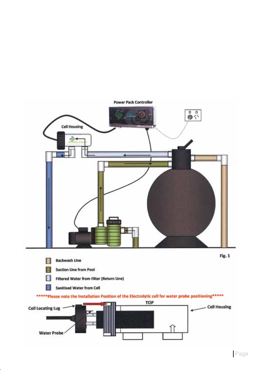
Cell Housing Installation
The electrolytic cell housing must be plumbed into the return line after the filter. Please see the installation
diagram, fig.1, below for the preferred method. If a heater is plumbed into the system then the cell housing
must be installed after the heater in the return line to protect the elements or heat exchanger. If a solar
heating system is installed then the cell housing should be fitted after the line going up to the roof and after
the return line coming back from the roof if it rejoins the main swimming pool return.
The cell housing has allocations for either 40mm PVC pipe or 50mm PVC pipe with the use of the supplied
PVC reducing bushes.
2
Page 4

Power Pack Installation
Mounting the Evolution chlorinator power pack is done by either using the supplied mounting bracket
or directly hanging on the wall with screws. If mounting directly on the wall, use the guide notches on
the top vents to position the holes for installation. The chlorinator power pack is to be mounted at least
800mm above ground level.
It is strongly recommended that the unit be installed where it is protected from the elements. Rain and
sunlight will prematurely age your unit. It should also be mounted in a position where it is away from
accidental water spray. The unit should be installed so that adequate air flow can circulate freely around
the power pack to allow the chimney drafting effect to perform efficiently.
Functions
Now that you have installed your Evolution power pack and cell correctly you can learn how to use it.
All Evolution Series chlorinators are fitted with a 240v 10A power socket located on the right hand
underside of the power pack. Your pool pump should be plugged into this socket so that the chlorinator
and pump activate together when the timer switches on at the allocated time settings or in a model
without a timer the pump and chlorinator is controlled by the on/off switch. 7 in fig 2..Failure to plug the
pool pump into this socket could lead to the chlorinator staying on with no water circulation. In case of
water probe failure, over heating and a possible gas build up may occur. This build up may shatter the
cell housing. Please see fig.2 below in regards to function control.
Fig 2.
3
Page 5

1. Chlorine Output LEDs – Fig.2
The output lights follow the curve of the distinguished Evolution logo. If the correct salt level is in the pool
then all 10 lights will illuminate. Each light represents 10% chlorine output. If all lights are not illuminated
then a higher salinity level will be required. Make sure all salt is dissolved properly before adding more.
The chlorine control, 2 in fig. 2, will increase or decrease the chlorine output to suit your chlorine demand.
If all of the indicator lights flash then there is a water fault problem.
2. Chlorine Control – Fig. 2
The chlorine controller determines the amount of chlorine production. By simply turning the control
clockwise you increase the chlorine output and by turning the control anti-clockwise you decrease the
chlorine output. Do not force the control past its stop as this will damage the unit and void warranty.
3. High Salt Light – Fig 2
This light is a red warning indicator and will only illuminate when the salt level in the swimming pool is
higher than 4500 parts per million. If this light is on, decrease the output by turning the chlorine control,
2 in fig.2., anticlockwise until the high salt (red light) goes off and the 10 chlorine output LEDs are on.
1 in fig 2. If this light is the only one illuminated then the unit has gone into over temperature cutout and
will reset once back to normal running temperature.
4. Polarity Light – Fig 2
The polarity light is the first indicator light, 10% in the chlorine output array, 4 in fig.2. This light will
alternate between orange and green every reversing cycle, 4-12 hours. Factory setting is a 12 hour cycle.
5. Timer – Fig 2
The FM/1 series time switch is designed for control of the chlorinator and circulation pump 24 hours.
Time Setting
To set the time, turn the minute hand clockwise. Do not set the time by rotating the “outer” dial.
Turn the minute hand clockwise until the time of day on the outer dial is aligned with the red marker on
the inner dial (nine o’clock position).
For example, to set the chlorinator and pool pump for 3.00pm, adjust the timer as per Fig 3. The inner
dial on the timer has 24 hr markings with 15 minute increments. Turn the minute hand clockwise until
15, 3.00pm, is aligned with the red mark on the inner dial. The hour and the minute dial will show exactly
3.00pm. It is very important to make sure that if you set the time to 3.00pm then the red mark on the
inner dial must point to 15 not 3, which would be 3.00am. The time switch is programmed by pushing
the captive trippers to the outer ring position for the entire period that the chlorinator and pump is to be
turned “ON”, i.e. each tripper is worth 15 minutes on the 24 hour dial. When the tripper is pushed in, the
timer is in the “OFF” position.
Manual Switch
Minute Hand
3.00pm must match the
red mark on the inner dial (15.00)
Comes on at 3.00pm (15.00) and
turns off at 7.00pm (19.00)
One Tripper is 15 Minutes
Fig 3
Inner Dial
Outer Ring
4
Page 6

6. Circuit Breaker
The circuit breaker mounted on the front right hand side of the Evolution chlorinator is designed to trip
out in the event of power surge or overload. When tripped the yellow centre button will pop out shutting
down the unit. To reset, press the yellow centre button back into resume normal function. Important
note, turn off the chlorinator at the power point before attempting to reset the circuit breaker.
Should the circuit breaker continue to trip then you should contact your local Evolution distributor.
7. Switch
Timer Model (A_TS): This switch allows you to choose the timer operation mode for your chlorinator and
pool pump. Switched to the left position, Timer, allows the chlorinator and pool pump to turn off and on
at your designated timer settings. The Manual selection, switched to the right, allows the chlorinator and
pump to work continuously until you physically change the chlorinator’s mode. The Off position in the
middle will turn the power off to the chlorinator and circulation pump.
No Timer Model (A_): This switch allows you to turn the chlorinator and pump ON and OFF only.
Maintenance
Some of the components have already been discussed in this manual in regards to keeping a happy
sparkling clean pool but here is a quick summary.
Correct pool water chemistry is a must so take your water sample to your local pool shop and have it
tested regularly. Even though you have purchased a self cleaning chlorinator, maintenance on the cell
is imperative to promote optimum chlorine production and cell life. Where the chlorinator is producing
Chlorine, a small amount of Calcium builds up on the cell plates. After 12 working hours Calcium may
stay attached to the edges of the plates or the water probe hence requiring cleaning. There are too
many variables to determine the regularity of cleaning the cell but it should be cleaned in a mild
Hydrochloric Acid solution,1 part acid to 10 parts water, at least every six months.
When cleaning the cell you must turn the chlorinator off or it will damage your unit and void
warranty. Do not use any utensils or harsh chemical cleaners to remove any calcium buildup from
the cell as it will damage the cell’s semi precious coating and again void warranty.
The chlorinator power pack should only be serviced by qualified electrical technicians. For your
nearest Evolution recommended service technician, please contact Evolution Water & Lighting Solutions
on +61 5565 0000 or email us on repairs@evolutionwls.com.au.
5
Page 7

TROUBLESHOOTING
Fault/Problem Possible Cause Remedy
NO FLOW
- All chlorine output
LED’s flashing as per
note 1. Page 4
HIGH SALT
- Red LED illuminated
3. Page 3
NO LIGHTS
LOW / NO CHLORINE
PRODUCTION
ABNORMAL CALCIUM
BUILDUP ON CELL
Pump turned off
Valves closed
Air in system
Dirty filter/Blockage
Low water level
Calcium buildup on water probe Sensor
Salt too high, above 4500ppm Turn chlorine control
Circuit Breaker tripped, 6. Page 3 Reset Circuit Breaker as per
Mains power failure Check switches and switchboard
Chlorine output too low Increase chlorine production as
Salt level too low
PH too high Adjust Ph between 7.2 – 7.4
Timer period too short Increase running time
High phosphate levels Add Starver
Cell connections
Calcium levels in swimming pool water
are extremely high or water chemistry
is not balanced
Ensure pump is on
Valves open
Check all o-rings and grease
Clean or Backwash filter
Fill up pool
Clean probe in a mild hydrochloric
acid – Page 5
anticlockwise as per note 3.
Page 4 until salt levels reduce
note 6. Page 5. If it trips again
immediately call a technician.
circuit breaker
per note 2. Page 4.
Increase salt level to 4000ppm and
check stabiliser (Cyanuric) levels
Check connections at junction
box under unit.
Get your water tested and
balanced as per the Langlier
Saturation Index Unit not
reversing, call a technician.
TIMER TIMES OUT
OF SYNC
OVER TEMPERATURE
- Red LED Illuminated
Only (no other lights)
3. Page 3
Timer not set correctly Check setting procedure as per
Chlorinator installed on off peak tariff Timer will need battery backup if
Timer / Off / Manual switch not switched
correctly
Salt Level too high, above 4500ppm Turn chlorine control anticlockwise
Installed in an area where the ambient
temperature is extremely high
note 5, Page 4
installed on off peak tariff
Make sure switch is selected as
per note 7, Page 5
as per note 3. Page 4 until salt
levels reduce.
Supply adequate cooling.
Install outside of the extreme
temperature.
6
Page 8

Warranty
Your Evolution Series Chlorinator is covered by a 3 year full warranty from the date of purchase.
The power pack controller and electrolytic cell are covered against defects in materials and assembly
from the date of purchase in a domestic application. All electrical or mechanical failure due to faulty
components will be repaired or replaced at no cost to the owner, including labour. Warranty will not be
given without proof of purchase, so keep your original purchase invoice in a safe place.
In field labour is limited to the Gold Coast city metropolitan area. Outside of these areas the complete
unit should be returned to Evolution Water & Lighting Solutions or one of our warranty agents. Freight
charges may apply and are completely at the discretion of Evolution Water & Lighting Solutions. Please
contact us in regards to a recognised warranty agent in your area.
Unfavourable environments and operating conditions beyond the control of the manufacturer such as
incorrect power supply (Must be 230V 50 Hz), the Evolution Series chlorinator plugged into an ancillary
device such as a Variable Frequency Drive, wear and tear, water and insect damage, extreme ambient
temperatures or any other adverse situation that affects the Evolution Series Chlorinator will void warranty.
All warranties only apply if the equipment is installed and operated in complete compliance with the
installation and operating instructions.
Evolution Series Chlorinators and electrolytic cells installed in a commercial situation are covered by
a 1 year warranty. Commercial situations meaning motels/hotels, health spas, apartment/town house
complexes and any situation with an unusually high bather load or abnormal conditions.
Evolution Water and Lighting Solutions will not accept liability for any consequential loss or damage of
any kind.
FOR ALL WARRANTY ENQUIRIES PLEASE DO NOT HESITATE TO CALL +61 7 5565 0000
OR EMAIL repairs@evolutionwls.com.au
7
Page 9

NOTES
8
Page 10

NOTES
9
Page 11

27/30 Mudgeeraba Road,
Worongary Queensland 4213
Phone 61 7 5565 0000 Fax 61 7 5565 0010
E. sales@evolutionwls.com.au
www.evolutionwls.com.au
10
Page 12

11
 Loading...