

Page 1
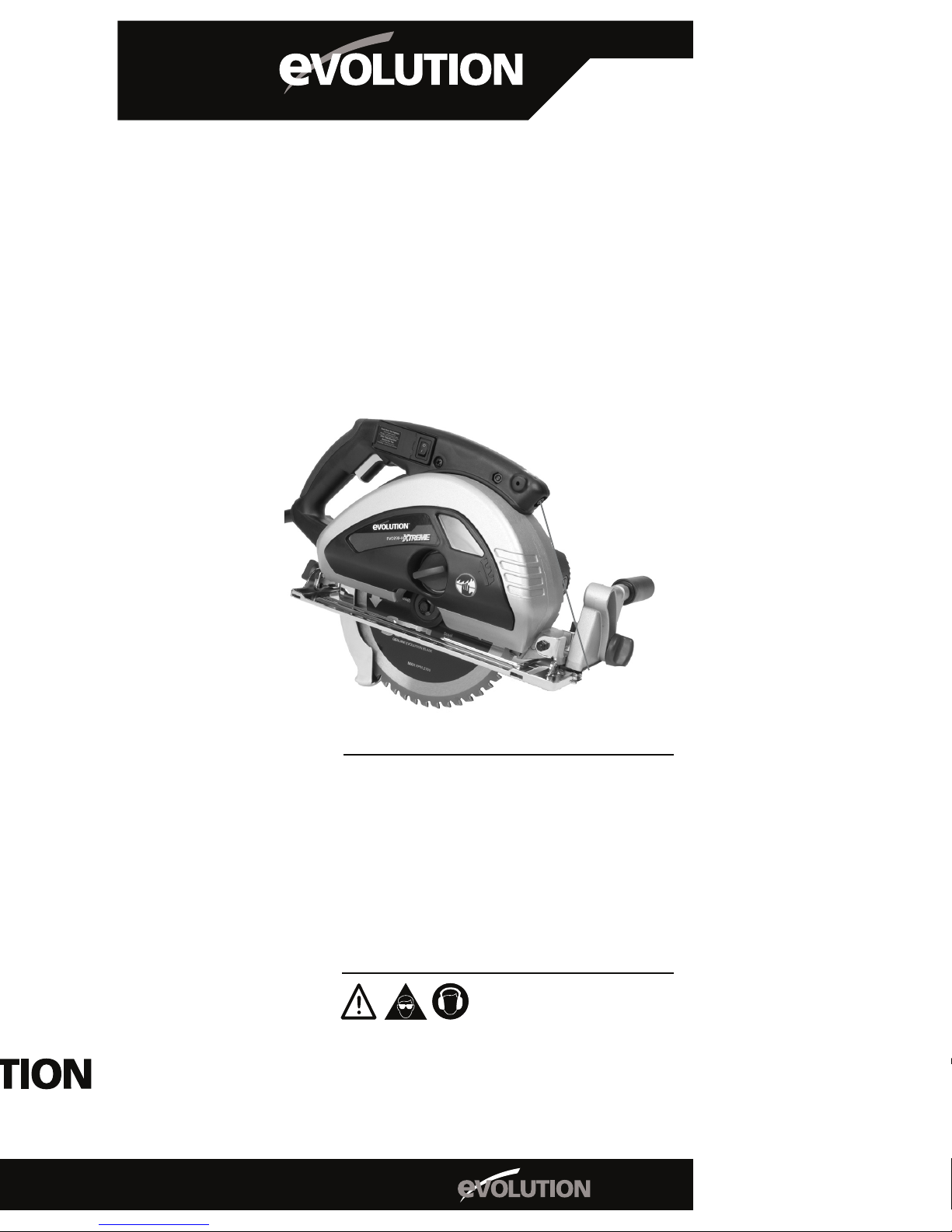
230mm (9”) TCT
STEEL CUTTING
CIRCULAR SAW
®
P O W E R T O O L S
STEEL
®
Instruction
Manual
Manuel d’Instruction
Instruktionshandbuch
Manual de Instrucción
Handleiding
Read instructions before operating this tool.
Lisez le mode d’emploi avant d’utiliser cet outil.
Vor Benutzung des Werkzuegs bitte bedienungsanleitungen
sorgfaltig lesen.
Antes de utilizar esta herramienta, lean las instrucciones.
Lees instructies alvorens dit hulpmiddel in werking te stellen.
®
Evolution 230-HDX
Page 2

2
Operating Instructions
Important
Please read these operating and safety instructions carefully and
completely. For your own safety, before using this equipment
check that the voltage is correct and that all handles and parts are
rmly secured. If you are uncertain about any aspect of using this
equipment contact your distributor.
Please Keep These Instructions
Model EVO230-HDX Specications
Motor (230v or 115v 50/60 Hz) (Watts): 1750
Maximum Box (1/4” 6mm Wall 900): 3-1/4” 84mm
Maximum Box (1/4” 6mm Wall 450): 2-1/16 53mm
Optimum Cutting Thickness (Mild Steel Plate): 1/2” 12mm
RPM No Load (min-1): 2700
Recommended Maximum Duty Cycle (Minutes): 30
Sound Pressure Level (Under Load) (dB(A)): 108.7
Vibration Level (Under Load) (m/s2): 3.9
Weight: 19-3/4lbs 9.0kg
Maximum Dimensions: 14-1/2”x15-3/4”x19-3/4” 370x400x500
Minimum Dimensions: 10”x12-3/4”x19-3/4” 250x325x500
Blade Dimensions
Maximum Diameter: 9” 230mm
Bore Diameter: 1” 25.4mm
Thickness: 1/16” 2mm
Standard Equipment Supplied With Unit: 1 Side Handle, 1 Fence Guide,
1 Safety Goggles, 1 Spanner attached to unit, 1 Carry Case, 2 Batteries,
Ear Plugs, 1 Operating Instructions.
Ear and eye protection MUST be worn while operating this
equipment. Do NOT touch the blade while it is in motion. Always
follow the Personal Protection Equipment (PPE) recommendations
while operating this tool.
This machine is designed for cutting steel using the appropriate TCT
(Tungsten Carbide Tipped) blades and accessories. It should NOT be
modied and / or used for any application other than for which it was
intended, including powering other equipment.
Ensure that the total work area can be viewed from the operating position.
Use barriers to keep people away. Do not operate the tool in explosive
environments – power tools create sparks that may ignite ammable
materials or gases. Do not operate the tool in damp or wet conditions,
as electric shocks may result. Always use both hands to operate the
tool. Always ensure that the material you are working on is securely
clamped.
• This tool is equipped with an approved cord and plug for its intended
Country of use.
• Remove plug from power supply before replacement of the blade,
making adjustments or other maintenance work.
• Use only genuine EVOLUTION brand saw blades.
• Inspect the machine and blade before each use and do not use
deformed, cracked, worn or otherwise damaged blades.
• Ensure the blade is correctly mounted and is appropriate for the
material to be cut.
• Do not use blades made of high-speed steel.
• Do not use blades that do not comply with the characteristics
specied in these instructions.
• Do not stop the blade by lateral pressure on the disc.
• Ensure that moveable guards operate freely without jamming.
Page 3

EC – Declaration of
Conformity
We, Evolution Power Tools Limited
Venture One
Longacre Close
Shefeld
S20 3FR
as the supplier of the product listed below:-
EVOLUTION 230mm XTREME Metal/
Steel Cutting Circular Saw
Part Number: EVO230X1/EVO230X2/EVO230X2EU
Voltage: 110/230v
Power: 1750W
Declare, under our sole responsibility that the equipment to which this
document relates, is in conformity with the following standards or other
normative documents:-
EN60335-1: 1994+A1+A2+A11-A16
EN55014-1: 2000+A1+A2
EN55014-2: 1997+A1
EN61000-3-2: 2000
EN61000-3-3: 1995+A1
EN61000-3-11: 2000
EN60745-1/A1:2003
EN60745-2-5:2003
and thereby conforms to the protection requirements of Council Directive
73/23/EEC amended by 93/68/EEC relating to the Low Voltage
Directive, Council Directive 98/37/EEC relating to the Machine Directive
and Council Directive 89/336/EEC relating to the EMC Directive,
and is compliant with Council Directive 2002/95/EC in relation to the
Restriction of Hazardous Substances in electrical & electronic equipment
(RoHS). EU Directive 2002/95/EC restricts the use of the 6 substances
below in the manufacture of specic types of electrical equipment. Whilst
this restriction does not legally apply to components, it is recognized that
component ‘compliance’ is relevant to many customers.
Evolution Power Tools’ denition of RoHS Compliance:
• The product does not contain any restricted substances in
concentrations and applications banned by the directive
• and for components, the product is capable of being worked at
the higher temperatures required by lead-free soldering.
The restricted substances and maximum allowed concentrations in
homogenous materials are, by weight:
Lead – 0.1%
Mercury – 0.1%
PBB (Polybrominated Biphenyis) – 0.1%
PBDE (Polybrominated Diphenyl Ethers) – 0.1%
Hexavalent Chromium – 0.1%
Cadmium – 0.01%
Level of Sound pressure according to 86/188/EEC, 98/37/EEC &
2000/14/EC:-
Guaranteed Sound Power Level:
108.7 dB(A)
All Relevant technical documentation is held at Evolution Power Tools
Ltd, Shefeld (UK).
Authorised by:
Mr Matthew J Gavins
Managing Director
9th May 2007
3
Page 4
• Never use the tool without the original protection guard system.
Do not lock the moving guard in the open position.
• Always keep the power cord away from moving parts of the tool.
• When you put the tool away, switch off the motor and ensure that all
moving parts have come to a complete standstill.
• In case of jamming, immediately switch off the tool and disconnect
the plug.
• Before using accessories, always compare the maximum allowed
RPM of the accessory with the RPM of the tool.
•
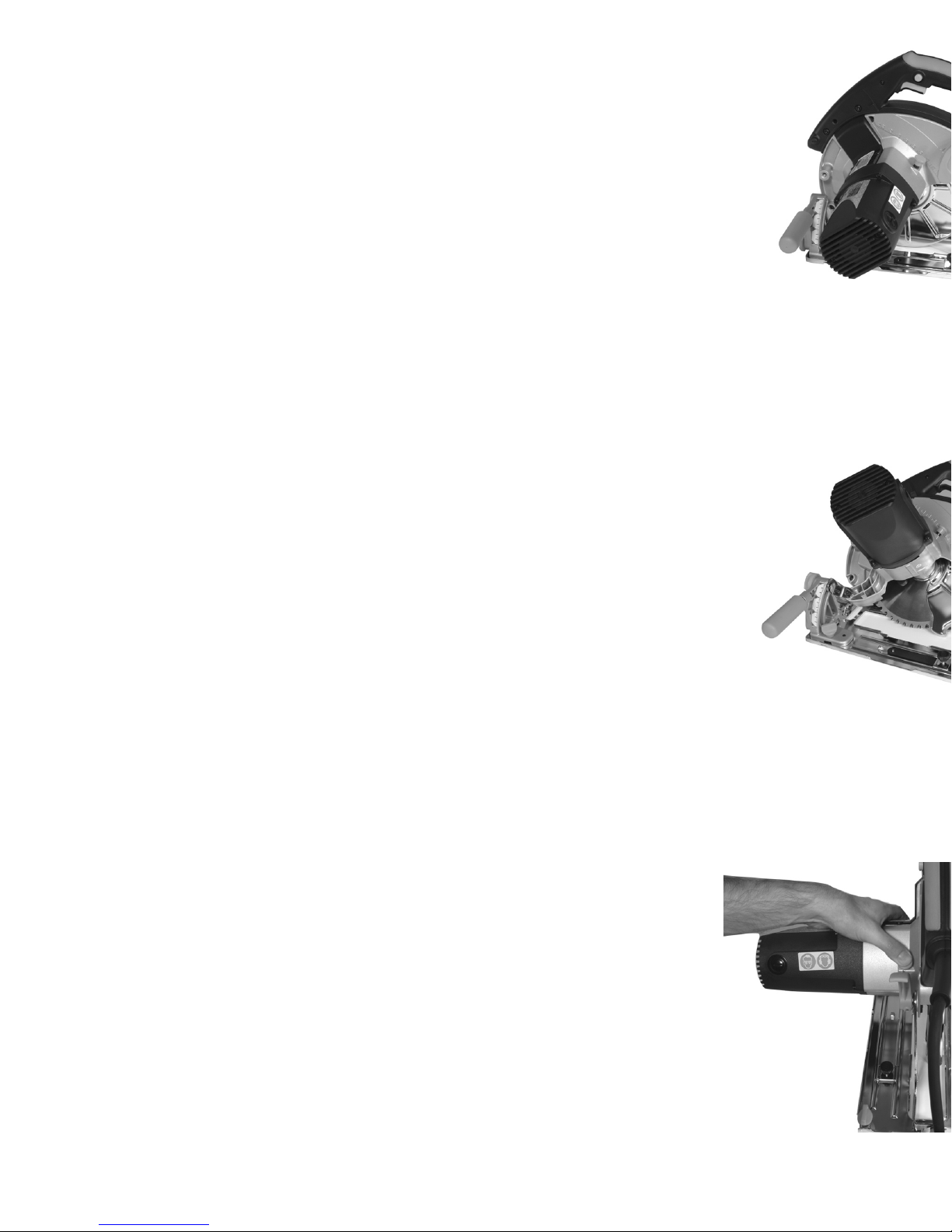
Ensure that the cutting depth adjustment handle, angle adjustment
handle, and side handle are rmly xed whilst using the tool (g. 1).
• Only use the anges and washers that are supplied with the tool,
and replace them if they become damaged or scored.
Machine Set Up
Mounting / Removing TCT Saw Blades
Remove the chip collection cover from the machine by undoing the knob.
Undo the two screws to release the inside blade guard. Loosen the screw
that retains the spanner to the machine and remove the spanner. Undo
the M13 bolt that secures the blade (g. 3) and remove the blade ange.
Note: Use spindle lock. Replace blade, making sure that the arrow for the
direction of rotation of the blade matches that of the machine then tighten
the M13 bolt with the ange in the correct position. Note: Check that the
spindle lock is fully released by manually rotating the blade before use.
Ret the spanner to the holder on the machine and tighten the retaining
screw.
Adjustment Of The Cutting Depth
Release the handle to adjust to the required cutting depth. Ensure that
the blade protrudes a maximum of 3/16” (4mm) through the material
being cut. Tighten the handle to lock in position. Note: The safety guard
(g. 1) is marked in increments from 0 – 84mm to assist in setting the
depth of cut.
Adjustment Of The Cutting Angle
Release both locking handles (g. 2) and adjust to the required cutting
angle by lining up the mark with the printed scale. Tighten both handles
to lock in position. Note: There are certain compound cuts on which it
may be necessary to manually retract the guard to allow the blade to
enter into and / or through the cut.
Line Of Cut Guide Slots
Guide slots are provided at the front of the saw base. The left slot is used
to follow a line when making a 90-degree cut. The right slot is used to
follow a line when making a 45-degree cut.
Operating Advice
Always clamp the work piece on a rigid support such as a bench or saw
horses where possible. This tool is equipped with a safety start feature –
to start the tool, you must rst push in the switch on the side of the handle
with your thumb – you can then depress the main trigger switch to power
the motor. Do not force the tool – let the speed of the saw blade do the
work. Cutting performance will not improve by applying more pressure
on the tool and blade life will be reduced. When using the parallel guide,
ensure that it is parallel with the blade and not the base of the tool, as
otherwise the blade and motor could become damaged. To set the guide,
loosen the two retaining screws, and slide it up snugly against the side of
the work piece. Retighten the screws to secure it in the desired position.
Place front edge of saw squarely on work before starting motor. When
starting a cut, sight the cutting line with the line of cut guide taking care to
introduce the blade to the material slowly, so as not to damage its teeth.
Use both hands to move the saw forward through the work piece.
Laser Sight Guide System
An additional feature of this machine is the laser sight system, which is
Fig. 1
Fig. 2
Fig. 3
4 31
Page 5
1.94
0.0
3.61
1.96
0.10
7.61
25.40%
0.00%
47.00%
25.70%
1.30%
1.23
0.0
4.50
0.001
0.0
5.731
intended as a guide only and should not be relied upon for the accuracy
of a cut. Remove the battery compartment cover and t the supplied
batteries, taking care to observe the correct polarity, then replace the
cover. Press the switch to the on position to activate, and remember to
turn off the laser when you have nished a cut. Before use the sight must
be aligned by means of the adjustment screw. Important Notice: Do
not point the laser at anyone and NEVER look into the laser light, as
serious eye damage may occur.
Chip Collection
This tool is provided with a chip collector compartment. When the chips
accumulate up to the see-through window, remove the cover, clean out
the cover, then replace it, and tighten the knobs. Notice: The metal chips
inside the cover may be very hot and sharp - do not touch with bare
hands.
Maintenance And Troubleshooting
Keep tool, cord, and carry case clean and free from chips. Avoid using
cleaning products, which include benzene, trichloroethelene, chloride,
or ammonia as these can damage plastic parts. In case of electrical or
mechanical malfunction, immediately switch off the tool and disconnect
the plug. Excessive sparking may indicate the presence of dirt in the
motor or worn out carbon brushes. Check for wear and replace when
they reach 1/4” (6mm). For all other service take machine to your local
dealer, or to Evolution Power Tools USA, Iowa, if bought in the USA.
Lubrication
Your machine gearbox is lubricated at the factory. To check and / or add
lubricant, it is necessary to dismantle the tool. This operation should
always be handled by the nearest SERVICE CENTER or Evolution
Power Tools USA, Iowa, if in the USA. All repairs and servicing made
by these centers are fully guaranteed against defective materials and
workmanship.
Accessories – Genuine Evolution Blades
40T 9” (230mm) TCT Wood Blade
48T 9” (230mm) TCT Mild Steel Blade
60T 9” (230mm) TCT Stainless Steel Capable Blade
80T 9” (230mm) TCT Aluminium Blade
Notice: Fair wear and tear and damage caused by misuse is not
covered under the 12-Month guarantee.
Gebruiksaanwijzing
Belangrijk
De gebruiksaanwijzing en veiligheidsvoorschriften aandachtig
doorlezen. Het voltage veriëren en controleren of alle handgrepen
en onderdelen stevig vastzitten met het oog op uw veiligheid. Neem
contact op met uw distributeur in geval van twijfel.
De gebruiksaanwijzing op een veilige plaats bewaren
Specicaties voor het EVO230-HDX model
Motor (230V of 115V 50/60 Hz) (Watt): 1750
Maximale zaagdiepte (6mm dikte 900) (mm): 84
Maximale zaagdiepte (6mm dikte 450) (mm): 53
Maximale Zaagdikte (Plaat in zacht staal) (mm): 12
RPM onbelast (min-1): 2700
Aanbevolen maximale werkduur (minuten): 30
Geluidsdrukniveau (belast) (dB(A)): 108.7
Trillingsniveau (belast) (m/s2): 3.9
Gewicht (Kg): 9.0
30 5
Page 6

Maximale afmetingen (mm): H 370 B 400 D 500
Minimale afmetingen (mm): H 250 B 325 D 500
Afmetingen blad
Maximale diameter (mm): 230
Diameter opening (mm): 25.4
Dikte (mm): 2
Meegeleverde standaarduitrusting: 1 zijhandgreep, 1 langsgeleider, 1
beschermbril, 1 op de zaag gemonteerde moersleutel, 1 draagkoffer, 2
batterijen, oorbeschermers en een gebruiksaanwijzing.
ALTIJD oorbeschermers en een beschermbril dragen tijdens het
gebruik van het gereedschap. GEEN bewegende zaagbladen
aanraken. Altijd de aanbevolen veiligheidsvoorschriften volgen
tijdens het gebruik van het gereedschap.
Het gereedschap is ontworpen voor het zagen van metaal met behulp
van de geschikte hardmetalen zaagbladen en accessoires. Het
gereedschap mag NIET omgebouwd worden en/of voor andere dan
de voorgeschreven doeleinden worden gebruikt met inbegrip van het
aandrijven van ander gereedschap.
Ervoor zorgen dat de totale werkruimte zichtbaar is vanaf de
bedieningsplaats. Installeer schermen om mensen uit de buurt te
houden. Het gereedschap niet in explosieve omgevingen gebruiken elektrisch gereedschap produceert vonken die ontbrandbaar materiaal
of gas kunnen ontvlammen. Het gereedschap niet in vochtige of
natte ruimten gebruiken om elektrische schokken te voorkomen. Het
gereedschap altijd met beide handen bedienen. Het werkstuk altijd
stevig vastklemmen.
• Het gereedschap is voorzien van een goedgekeurd snoer en stekker
voor het land van gebruik.
• De stekker voor de vervanging van zaagbladen, afstelling en andere
onderhoudswerkzaamheden uit het stopcontact verwijderen.
• Uitsluitend originele EVOLUTION zaagbladen gebruiken.
• De zaag en het zaagblad voor elk gebruik inspecteren en geen
vervormde, gebarsten, versleten of beschadigde zaagbladen
gebruiken.
• Veriëren of het zaagblad naar behoren gemonteerd is en geschikt
is voor het te zagen materiaal.
• Geen snelstalen zaagbladen gebruiken.
• Geen zaagbladen gebruiken die niet aan de technische gegevens
voldoen.
• Het zaagblad niet stoppen door zijwaartse druk op de schijf
uitoefenen.
• Ervoor zorgen dat de beweegbare beschermkappen vrij kunnen
bewegen.
• Het gereedschap nooit zonder de originele beschermkap
gebruiken. De beweegbare beschermkap nooit in de geopende
stand vergrendelen.
• Het netsnoer altijd uit de buurt van de bewegende delen van het
gereedschap houden.
• De zaag uitschakelen en veriëren of alle bewegende delen volledig
stilstaan voordat u het gereedschap opbergt.
• Het gereedschap bij vastlopen onmiddellijk uitschakelen en de
stekker uit het stopcontact verwijderen.
• Voor het gebruik van accessoires altijd het maximum toegestane
toerental van de accessoire met het toerental van het gereedschap
vergelijken.
• Ervoor zorgen dat de zaagdiepte verstelknop, de schuininstelknop
en de zijhandgreep stevig vastzitten tijdens het gebruik van het
gereedschap (g. 1).
• Uitsluitend de meegeleverde enzen en onderlegringen gebruiken
en deze vervangen zodra ze beschadigd of bekrast zijn.
PROTEZIONE DELL'AMBIENTE
Ricicli i materiali indesiderabili invece di averli come spreco.
Tutti gli attrezzi, tubi essibili ed imballaggio dovrebbero essere
classicati , presi al centro di riciclaggio locale ed essere disfatti
di in una forma sicura per il condizione ambientale .
Lista di Analisi di Materiali Riciclabile
Materiale Peso (Kg) Percentage ( % )
Alluminio
Ferro di Getto
Placato di Ferro
Plastiche
Altri
Totale
1.94
0.0
3.61
1.96
0.10
7.61
25.40%
0.00%
47.00%
25.70%
1.30%
Major Packaging Materials
Materiale Peso (Kg)
Cartone
Polistirolo
Polietilene di Densità Bassa
Polipropilene
Altri
Totale
1.23
0.0
4.50
0.001
0.0
5.731
MILJØVERN
Resirkuler uønskede materialer i stedet for å kvitte seg
med dem som avfall. Alle verktøy, slanger, emballasje bør
sorteres, tatt til det lokale resirkulerings senter og kvitte seg
med det på en miljømessig trygg måte.
Resirkulerbare Materialer Analyse Liste
Material Vekt (Kg) Prosentsats ( % )
Aluminium
Støpejern
Jern plate
Plastikk
Annet
Total
1.94
0.0
3.61
1.96
0.10
7.61
25.40%
0.00%
47.00%
25.70%
1.30%
Hoved Emballasje Materialer
Material Vekt (Kg)
Kartong
Polystyren
Lav Tetthet Polyethylen
Polipropylen
Annet
Total
1.23
0.0
4.50
0.001
0.0
5.731
YMPÄRISTÖN SUOJELU
Kierrätä tarpeeton materiaali äläkä jätä niitä jätteiksi.
Kaikki työkalut, letkut ja pakkausmateriaali tulee lajitella
ja toimittaa paikalliseen kierrätyskeskukseen, jossa ne
käsitellään ympäristöystävällisellä tavalla
Luettelo kierrätyskelpoisista materiaaleista
Materiaali Paino (Kg) Prosenttimäärä ( % )
Alumi
Valurauta
Rautalevyt
Muovi
Muut
Yhteensä
1.94
0.0
3.61
1.96
0.10
7.61
25.40%
0.00%
47.00%
25.70%
1.30%
Pakkausmateriaalit
Materiaali Paino (Kg)
Pahvikartonki
Polystyreeni
Huokoinen Polyethyleeni
Polypropyleeni
Muut
Yhteensä
1.23
0.0
4.50
0.001
0.0
5.731
6 29
Page 7
1.94
0.0
3.61
1.96
0.10
7.61
25.40%
0.00%
47.00%
25.70%
1.30%
1.23
0.0
4.50
0.001
0.0
5.731
1.94
0.0
3.61
1.96
0.10
7.61
25.40%
0.00%
47.00%
25.70%
1.30%
1.23
0.0
4.50
0.001
0.0
5.731
1.94
0.0
3.61
1.96
0.10
7.61
25.40%
0.00%
47.00%
25.70%
1.30%
1.23
0.0
4.50
0.001
0.0
5.731
Installatie van zaag
Montage / demontage van hardmetalen zaagblad
Verwijder het deksel van de spaanafzuiger van de zaag door de knop los
te draaien. Draai de twee schroeven los om de binnenste beschermkap
van het zaagblad te verwijderen. Draai de schroef los waarmee de
moersleutel op de zaag is vastgezet en verwijder de moersleutel. Draai
de M13 bout los waarmee het zaagblad (g. 3) is vastgezet en verwijder
de ens van de zaag. N.B.: Gebruik de asvergrendeling. Vervang het
zaagblad en zorg ervoor dat de pijl van de rotatierichting van het zaagblad
overeenkomt met de pijl op de zaag en draai hierna de M13 bout met
de ens op de juiste plaats vast. N.B.: Verieer of de asvergrendeling
uitgeschakeld is door het zaagblad voor het gebruik met de hand te
draaien. Monteer de sleutel opnieuw in de houder op de zaag en draai
de borgschroef vast.
Afstellen van zaagdiepte
Draai de hendel los om de juiste zaagdiepte in te stellen. Zorg ervoor dat
het zaagblad maximaal 4 mm boven het te zagen materiaal uitsteekt.
Draai de hendel vast. N.B.: De beschermkap (g. 1) is voorzien van
incrementen van 0 tot 84 mm om het afstellen van de zaagdiepte te
vergemakkelijken.
Schuininstelling
Draai beide vergrendelingen (g. 2) los en stel de juiste hoek in door
de merkstreep met de graadverdeling uit te lijnen. Draai beide hendels
opnieuw vast. N.B.: Bij bepaalde samengestelde zaagsneden kan het
nodig zijn om de beschermkap met de hand terug te trekken zodat het
zaagblad in en/of door de snede geïntroduceerd kan worden.
Zaaglijn geleidegleuven
De voorkant van de zaagzool is voorzien van geleidegleuven. De
linkergleuf wordt gebruikt om een zaaglijn bij een zaagsnede van
90° te volgen. De rechtergleuf wordt gebruikt om een zaaglijn bij een
versteksnede van 45° te volgen.
Bedieningsvoorschriften
Het werkstuk altijd op een onbuigzaam steunstuk zoals een werkbank of
zaagbok vastklemmen indien mogelijk. Het gereedschap is voorzien van
een startbeveiliging – om het gereedschap te starten moet u eerst op de
schakelaar op de zijkant van de hendel drukken met uw duim - hierna
kunt u op de hoofdschakelaar drukken om de zaag in te schakelen.
Het gereedschap niet forceren – laat de snelheid van het zaagblad al
het werk doen. De zaagprestatie wordt niet verbeterd door meer druk
op het gereedschap uit te oefenen en de levensduur van het zaagblad
wordt verkort. Bij het gebruik van de parallelgeleider dient u ervoor te
zorgen dat de geleider parallel met het zaagblad is en niet met de zool
van de zaag, aangezien het zaagblad en de motor anders beschadigd
worden. Om de geleider in te stellen, dient u de twee borgschroeven los
te draaien en de geleider dicht tegen de zijkant van het werkstuk aan te
duwen. Draai de schroeven opnieuw vast om de geleider in de gewenste
stand vast te zetten. Plaats de voorkant van de zaag haaks op het
werkstuk voordat u de motor start. Voor het beginnen met zagen moet de
zaaglijn met de geleider worden uitgelijnd en het zaagblad langzaam op
het materiaal geplaatst worden zodat de tanden niet worden beschadigd.
Beide handen gebruiken om de zaag voorwaarts door het werkstuk te
bewegen.
Lasergeleider
Een aanvullende functie van de zaag is de lasergeleider die uitsluitend
als geleider fungeert en niet voor de precisie van de zaagsnede zorgt.
Verwijder het klepje van de batterijhouder en leg de meegeleverde
batterijen hierin waarbij u de juiste polariteit in acht dient te nemen
en plaats het klepje terug. Duw de schakelaar in de Aan stand om de
geleider in te schakelen en vergeet niet om de lasergeleider na het
zagen weer uit te schakelen. De geleider moet door middel van de
28 7
Page 8
8
stelschroef uitgelijnd worden. Belangrijk: De laser niet op personen
richten en NOOIT in het laserlicht kijken aangezien dit ernstig
oogletsel kan veroorzaken.
Spaanafzuiger
Het gereedschap is voorzien van een spaanafzuiger. Verwijder het
deksel zodra de spanen zich tot aan het kijkvenster ophopen, leeg de
spaanafzuiger, plaats het deksel terug en draai de knoppen vast. N.B.:
De metaalspanen in de spaanafzuiger zijn erg heet en scherp - niet met
blote handen aanraken.
Onderhoud en foutopsporing
Het gereedschap en het snoer schoon houden. Geen reinigingsproducten
op basis van benzeen, trichloorethyleen, chloride en ammoniak
gebruiken aangezien de plastic onderdelen hierdoor beschadigd
worden. Het gereedschap onmiddellijk uitschakelen en de stekker uit het
stopcontact halen in het geval van elektrische of mechanische storingen.
Buitensporige vonkoverslag duidt meestal op de aanwezigheid van
vuil in de motor of versleten koolborstels. De koolborstels op slijtage
controleren en vervangen zodra ze 6 mm hoog zijn. Het gereedschap
voor alle andere reparaties en onderhoudsbeurten naar een erkend
servicecentrum brengen.
Smering
De zaag werd in de fabriek gesmeerd. Het gereedschap moet
gedemonteerd worden om het smeermiddelniveau te controleren of bij
te vullen. Dit dient altijd door het dichtstbijzijnde SERVICECENTRUM
te gebeuren. Op alle door de servicecentra uitgevoerde reparaties
en onderhoudswerkzaamheden wordt een volledige garantie tegen
materiaal- en fabricagefouten verstrekt.
Accessoires – Originele Evolution zaagbladen
40T 230mm TCT Blad voor hout
48T 230mm TCT Blad voor zacht staal
60T 230mm TCT Blad voor roestvrij staal
80T 230mm TCT Blad voor aluminium
N.B.: Buitensporige slijtage en beschadiging veroorzaakt door
onoordeelkundig gebruik worden niet door de garantie van 12
maanden gedekt.
Mode d’emploi
Important
Lire attentivement le mode d’emploi et les consignes de sécurité.
Pour des raisons de sécurité, vérier le voltage et la xation des
poignées et des pièces avant d’utiliser la scie. Contacter votre
distributeur en cas de doute.
Conserver ces instructions
Spécications du modèle EVO230-HDX
Moteur (230 v ou 115 v 50/60 Hz) (Watts): 1750
Capacité maxi de découpe de boîte (paroi 6 mm 900) (mm): 84
Capacité maxi de découpe de boîte (paroi 6 mm 450 ) (mm): 53
Epaisseur de coupe maxi (tôle en acier doux) (mm): 12
Vitesse à vide (tmn) (min-1): 2700
Cycle de marche maxi recommandé (minutes): 30
Niveau sonore (en charge) (dB (A)): 108.7
Niveau de vibrations (en charge) (m/s2): 3.9
Poids (kg): 9.0
Dimensions maxi (mm): Haut 370 Larg 400 Prof 500
Dimensions mini (mm): Haut 250 Larg 325 Prof 500
Dimensions de lame
Per qualsiasi altro intervento di manutenzione rivolgersi al Distributore.
Lubricazione
La scatola ingranaggi del vostro elettroutensile è lubricata all’atto della
produzione. Per controllare e/o aggiungere lubricante è necessario
smontare l’elettroutensile. L’operazione deve essere effettuata dal centro
di manutenzione indicato dal Distributore. Ogni intervento di manutenzi-
one effettuato da un centro autorizzato è coperto da garanzia per mate-
riali difettosi e manodopera.
Accessori - Lame Evolution originali
40T 230mm Rossa 40 denti Lama TCT legno
48T 230mm Blu 48 denti Lama TCT acciaio
60T 230mm Gialla 60 denti Lama TCT inox
80T 230mm Verde 80 denti Lama TCT alluminio
Attenzione: L’usura normale, le rotture e i danni causati da utilizzo
improprio NON sono coperti dalla garanzia di 12 mesi.
27
Page 9

Diamètre maxi (mm): 230
Diamètre d’alésage (mm): 25.4
Epaisseur (mm): 2
La scie est livrée en standard avec : 1 poignée latérale, 1 guide de
refend, 1 paire de lunettes de protection, 1 clé montée sur la scie, 1
coffret, 2 batteries, des protecteurs anti-bruit et le mode d’emploi.
Les protecteurs anti-bruit et les lunettes de protection DOIVENT
être portés lors de l’utilisation de la scie. NE PAS toucher la lame
en mouvement. Toujours suivre les consignes de protection
individuelle lors de l’utilisation de l’outil.
La scie a été conçue pour couper de l’acier à l’aide de lames en carbure
et des accessoires. La scie NE PEUT être modiée et/ou utilisée
pour des applications autres que celles recommandées, y compris
l’alimentation d’autres outils.
S’assurer que la zone de travail est entièrement visible du côté opérateur.
Utiliser des écrans pour tenir les personnes à l’écart. Ne pas utiliser
l’outil dans un environment explosif - les outils motorisés produisent des
étincelles qui peuvent allumer des substances ou des gaz inammables.
Ne pas utiliser l’outil dans un environnement humide puisque ceci peut
provoquer des chocs électriques. Toujours utiliser l’outil à deux mains.
Toujours s’assurer que la pièce à découper est bien serrée.
• Cet outil est équipé d’un câble d’alimentation et d’une che
approuvés pour le pays d’utilisation.
• Débrancher la scie du secteur avant le remplacement de la lame, le
réglage ou d’autres travaux d’entretien.
• N’utiliser que des lames de scie de la marque EVOLUTION.
• Inspecter la scie et la lame avant chaque utilisation et ne pas
utiliser des lames déformées, ssurées, usées ou endommagées.
• S’assurer que la lame est montée correctement et convient au
matériau à découper.
• Ne pas utiliser des lames en acier rapide.
• Ne pas utiliser des lames qui ne répondent pas aux spécications
du mode d’emploi.
• Ne pas arrêter la lame en exerçant une pression latérale sur le
disque.
• S’assurer que les carters mobiles peuvent fonctionner sans
bloquer.
• Ne jamais utiliser l’outil sans les carters de protection
d’origine. Ne pas verrouiller le carter mobile dans la position
ouverte.
• Toujours écarter le câble d’alimentation des pièces en mouvement
de l’outil.
• Mettre hors marche le moteur et s’assurer que toutes les pièces en
rotation se sont arrêtées complètement avant de ranger l’outil.
• Immédiatement mettre l’outil hors marche et débrancher la che en
cas de blocage.
• Avant d’utiliser les accessoires il faut toujours vérier si les
tours par minute de l’accesoire et les tours par minute de l’outil
correspondent.
• S’assurer que le bouton de réglage de la profondeur de coupe, le
bouton de réglage d’angle et la poignée latérale sont bien serrés
lors de l’utilisation de l’outil (Fig. 1).
• N’utiliser que les brides et les rondelles livrées avec l’outil et les
remplacer lorsqu’elles sont endommagées ou rainées.
Installation de la scie
Montage / démontage des lames en carbure de tungstène
Retirer le capot récupérateur copeaux de la machine en desserrant le
bouton. Dévisser les deux vis an de pouvoir retirer le protège-lame.
Desserrer la vis qui xe la clé sur la scie et retirer la clé. Desserrer la
boulon M13 qui xe la lame (Fig. 3) et retirer la bride de la lame. Nota
26 9
Page 10

: Utiliser le bouton de blocage d’arbre. Replacer la lame en s’assurant
que la èche de la direction de rotation de la lame correspond à celle
de la scie et serrer ensuite le boulon M13 avec la bride dans la position
correcte. Nota : Vérier si le bouton de blocage d’arbre est enclenché en
tournant la lame à la main avant l’utilisation de la scie. Replacer la clé
dans la porte-outils sur la scie et serrer la vis de retenue.
Réglage de la profondeur de coupe
Desserrer le bouton pour régler la profondeur de coupe souhaitée.
S’assurer que la lame dépasse d’une hauteur de 4 mm par rapport au
matériau à découper. Serrer le bouton. Nota : Des incréments de 0 à 84
mm sont gravés sur le carter de protection (Fig. 1) pour aider l’opérateur
à régler la profondeur de coupe.
Réglage de l’angle de coupe
Desserrer les deux boutons de blocage (Fig. 2) et régler à l’angle de
coupe souhaitée en alignant le cran de blocage avec l’échelle graduée.
Serrer les deux boutons. Nota : Pour certaines coupes composées, il
peut être nécessaire d’escamoter le protège-lame an d’introduire la
lame dans et/ou à travers la coupe.
Rainures de guidage du trait de coupe
La face avant de la semelle de la scie est munie de rainures de guidage.
La rainure de gauche est utilisée pour suivre le trait de coupe lors d’une
coupe d’angle de 90°. La rainure de droite est utilisée pour suivre le trait
de coupe lors d’une coupe d’angle de 45°.
Consignes d’utilisation
Toujours serrer la pièce à découper sur un support rigide tel qu’un étai ou
un chevalet de scieur où possible. La scie est équipée d’un interrupteur
de sécurité - pour mettre l’outil en marche il faut d’abord appuyer sur
l’interrupteur sur le côté de la poignée avec le pouce et ensuite appuyer
sur la gâchette pour démarrer le moteur. Ne pas forcer la scie – laisser
la vitesse de la lame de scie faire le travail. La performance de coupe
ne s’améliorer pas en exerçant plus de pression sur la scie et réduira
la durée de vie de la lame. Lors de l’utilisation d’un guide parallèle,
s’assurer que le guide est parallèle à la lame et non à la semelle de
la scie ce qui pourrait endommager la lame et le moteur. Pour régler le
guide, desserrer les deux vis de retenue et poser le guide contre le côté
de la pièce à découper. Resserrer les vis pour xer le guide dans sa
place. Poser l’arête de la scie sur la pièce à découper avant de mettre le
moteur en marche. Avant de découper la pièce il faut aligner le trait de
coupe avec le guide de coupe en introduisant la lame lentement dans le
matériau an de ne pas endommager la denture. Utiliser les deux mains
pour pousser la scie à travers la pièce à découper.
Guide à laser
Une caractéristique supplémentaire de la scie est le guide à laser pour
la découpe des pièces. Attention : le guide n’assure pas la précision de
coupe. Retirer le couvercle du compartiment de batteries et introduire
les batteries fournies en observant la polarité appropriée et replacer le
couvercle. Pousser le bouton en position marche pour actionner et ne
pas oublier de mettre le guide laser hors marche après avoir ni la coupe.
Le guide doit être aligné à l’aide de la vis de réglage avant d’utiliser la
scie. Important : Ne pas orienter le laser vers des personnes et NE
JAMAIS regarder la lumière laser pour éviter de graves blessures
aux yeux.
Collecteur de copeaux
La scie est équipée d’un collecteur de copeaux. Lorsque les copeaux
couvrent la fenêtre transparente, il faut retirer le couvercle, vider le
collecteur et le remplacer et reserrer les boutons. Nota : Les copeaux de
métal dans le collecteur peuvent être très chauds et tranchants - ne pas
toucher à mains nues.
one in cui si opera. Utilizzare opportuni sbarramenti per i non addetti ai
lavori. Non utilizzare l’elettroutensile in aree a rischio di esplosione: le
scintille generate potrebbero innescare incendi o esplosioni di sostanze
o gas inammabili. Non utilizzare l’elettroutensile in aree bagnate o in
condizioni di alta umidità per evitare il rischio di cortocircuiti. Utilizzare
l’elettroutensile operando sempre con entrambe le mani. Assicurarsi
sempre che il materiale da tagliare sia opportunamente ssato.
• Questo elettroutensile è equipaggiato con cavo di alimentazione e
spina adatti alle normative del vostro paese.
• Staccare sempre la spina prima di cambiare la lama, effettuare
regolazioni o qualsiasi intenvento di manutenzione.
• Utilizzare esclusivamente lame originali Evolution.
• Controllare l’elettroutensile e la lama prima di ogni lavoro e non
• utilizzare lame deformate, crepate, consumate o in qualche
modo danneggiate.
• Non utilizzare lame in acciaio rapido.
• Non utilizzare lame che non corrispondano alle caratteristiche
indicate in queste istruzioni.
• Non bloccare la lama con la pressione laterale sul disco.
• Assicurarsi che le protezioni mobili operino correttamente senza
intoppi.
• Non utilizzare mai l’elettroutensile senza i dispositivi di protezione.
• Non bloccare le protezioni in posizione aperta.
• Tenere il cavo di alimentazione lontano dalle parti in movimento
dell’elettroutensile.
• Prima di riporre l’elettroutensile controllare che l’interruttore sia
spento e vericare che le parti in movimento siano effettivamente
ferme.
• In caso di bloccaggio spegnere immediatamente l’elettroutensile e
staccare il cavo di alimentazione.
• Prima di utilizzare qualsiasi accessorio controllare che la velocità
max consentita corrisponda alla velocità max dell’elettroutensile.
• Utilizzare esclusivamente rondelle e ange originali fornite con
l’elettroutensile e sostituirle se danneggiate.
• Assicurarsi che la manopola di regolazione della profondità di
taglio, la manopola della regolazione dell’inclinazione e la mano
pola laterale siano serrate a fondo. (vedi gura qui di seguito)
MESSA IN FUNZIONE
Montaggio/Smontaggio lama
Rimuovere dall’elettroutensile il coperchio del comparto per la raccolta
trucioli girando la manopola. Svitare il bullone M13 di bloccaggio della
lama e rimuovere la angia di bloccaggio come indicato in gura: At-
tenzione: eliminare con uno straccio pulito eventuali residui oleosi sulla
angia; bloccare il movimento dell’albero motore. Inserire la lama veri-
cando che la freccia che indica la rotazione della lama corrisponda al
senso di rotazione della freccia dell’elettroutensile. Inserire la angia in
posizione corretta e serrare a fondo il bullone di bloccaggio. Attenzione:
rilasciare la leva di bloccaggio dell’albero posizionandola come indicato
vericando che il movimento della lama sia perfettamente libero ruotan-
dola manualmen te come indicato in gura:
Regolazione angolo di taglio
Rilasciare entrambe le manopole di bloccaggio della guida come
indicato in gura: e regolare l’inclinazione come desiderato allineando
la tacca alla scala graduata. Serrare a fondo entrambe le manopole. At-
tenzione: il taglio di materiali compositi potrebbe richiedere di sollevare
manualmente la guida per consentire alla lama di mordere efcace-
mente il pezzo ta tagliare.
Linea di taglio
Sul fronte dell’elettroutensile sono riportate due tacche per indicare la
linea di taglio rispettivamente per tagli a 90° e 45°
10 25
Page 11

IIMPORTANTE!
consultazioni.
elettroutensile.
Entretien et dépannage
Garder l’outil et le câble d’alimentation propres. Ne pas utiliser des
nettoyants à base de benzène, trichloroéthylène, chloride et ammoniac
puisqu’ils peuvent endommages les pièces en plastique. Mettre l’outil
immédiatement hors marche et hors tension en cas d’un mauvais
fonctionnement électrique ou mécanique. Un jaillissement d’étincelles
indique en général la présence d’impuretés dans le moteur ou des balais
en charbon usés. Vérier l’usure des balais en charbon et remplacer
lorsqu’ils ont une épaisseur de 6 mm. Apporter la scie à un centre de
réparation accrédité pour toute autre réparation ou entretien.
Lubrication
La boîte de vitesse de votre machine a été lubriée à l’usine. Pour verier
le lubriant et / ou en ajouter, il est nécessaire de démonter l’outil. Le
démontage doit toujours être effectué par le CENTRE DE SERVICE
ACCREDITE le plus proche. Les réparations et l’entretien effectués par
ces centres sont entièrement garantis contre les vices de fabrication et
de matériaux.
Accessoires – Lames de la marque Evolution
40T 230 mm lame en carbure pour bois
48T 230 mm lame en carbure pour acier doux
60T 230 mm lame en carbure pour acier inoxydable
80T 230 mm lame en carbure pour aluminium
Nota : L’usure excessive et les dommages provoqués par une
utilisation anormale ne sont pas couverts par la garantie de 12
mois.
Bedienungsanleitung
Wichtig
Bitte lesen Sie die Bedienungsanleitung und die Sicherheitshinweise
vollständig. Zu Ihrer Sicherheit, überprüfen Sie bitte vor jeder
Benutzung, dass die Spannung der Stromquelle mit den Angaben
auf dem Typenschild des Gerätes übereinstimmt, und dass alle
Handgriffe und Geräteelemente sicher montiert sind. Sollten Sie zu
irgendeinem Aspekt der Bedienung dieses Gerätes Fragen haben,
wenden Sie sich bitte an Ihren Händler.
Diese Bedienungsanleitung bitte aufbewahren
Technische Daten, Modell EVO230-HDX
Motor (230v oder 115v 50/60 Hz) (Watt): 1750
Maximale Kastenschnittleistung (6mm Wand 900) (mm): 84
Maximale Kastenschnittleistung (6mm Wand 450) (mm): 53
Maximale Schnittdicke (Weichstahlblech) (mm): 12
Leerlaufdrehzahl (min-1): 2700
Empf. Höchstdauer für ununterbrochenen Betrieb (Minuten):
30
Schalldruckpegel (unter Last) (dB(A)): 108.7
Vibrationspegel (unter Last) (m/s2): 3.9
Gewicht (kg): 9.0
Maximale Abmessungen (mm): H 370 B 400 T 500
Mindestabmessungen (mm): H 250 B 325 T 500
Sägeblatt
Maximaler Durchmesser (mm): 230
Aufnahmebohrungsdurchmesser (mm): 25.4
Dicke (mm): 2
Im Lieferumfang des Gerätes enthaltene Standardausrüstung: 1
seitlicher Handgriff, 1 Führungsanschlag, 1 Schutzbrille, 1 am Gerät
befestigter Schraubenschlüssel, 1 Tragekoffer, 2 Batterien, Ohrstöpsel
und diese Bedienungsanleitung.
24 11
Page 12

Beim Arbeiten mit diesem Gerät MÜSSEN ein Gehörschutz sowie
eine Schutzbrille getragen werden. NICHT mit dem rotierenden
Sägeblatt in Berührung kommen. Beachten Sie beim Arbeiten
mit diesem Gerät immer die Empfehlungen zum Schutz vor
Verletzungen.
Dieses Gerät ist bestimmt zum Schneiden von Stahl, unter Verwendung
geeigneter wolframkarbidbestückter Sägeblätter und Zubehörteile.
Es darf NICHT modiziert und/oder für andere als den beabsichtigten
Zweck benutzt werden, einschließlich als Antrieb für andere Geräte.
Stellen Sie sicher, dass der gesamte Arbeitsbereich von der
Bedienerposition aus eingesehen werden kann. Benutzen Sie
Absperrungen, um Personen vom Arbeitsbereich fernzuhalten.
Benutzen Sie das Gerät nicht in explosionsgefährdeten Bereichen –
Elektrowerkzeuge erzeugen Funken, die entammbare Werkstoffe oder
Gase in Brand setzen können. Benutzen Sie das Gerät nicht in feuchten
oder nassen Umgebungen bzw. Bereichen. Es besteht Gefahr eines
elektrischen Schlages. Beim Arbeiten das Gerät immer fest mit beiden
Händen halten. Kontrollieren Sie immer, dass das zu bearbeitende
Werkstück sicher eingespannt ist.
• Kabel und Gerätestecker dieses Gerätes sind für das
Bestimmungsland zugelassen.
• Vor dem Wechseln des Sägeblatts, allen Einstellungen oder
anderen Wartungsarbeiten immer zuerst den Gerätestecker aus
der Netzsteckdose ziehen.
• Benutzen Sie nur Originalsägeblätter der Marke EVOLUTION.
• Kontrollieren Sie Gerät und Sägeblatt vor jeder Benutzung und
benutzen Sie keine verbogenen, rissigen, abgenutzten oder
anderweitig beschädigten Sägeblätter.
• Vergewissern Sie sich, dass das Sägeblatt korrekt montiert und für
das zu schneidende Material geeignet ist.
• Verwenden Sie keine Sägeblätter aus hochlegiertem
Schnellarbeitsstahl (HSS-Stahl).
• Verwenden Sie keine Sägeblätter, die den in dieser
Bedienungsanleitung spezizierten Eigenschaften nicht
entsprechen.
• Sägeblätter nicht durch seitliches Gegendrücken abbremsen.
• Stellen Sie sicher, dass die beweglichen Schutzvorrichtungen sich
frei bewegen können, ohne festzuklemmen.
• Niemals mit dem Gerät ohne die Originalschutzvorrichtunge
n arbeiten. Die Pendelschutzhaube darf nicht in geöffnetem
Zustand festgeklemmt werden.
• Halten Sie das Netzkabel immer von den beweglichen Geräteteilen
fern.
• Wenn Sie das Gerät ablegen, schalten Sie den Motor aus und
vergewissern Sie sich, dass alle beweglichen Teile zum völligen
Stillstand gekommen sind.
• Wenn das Sägeblatt blockiert, Gerät sofort ausschalten und den
Gerätestecker aus der Netzsteckdose ziehen.
• Vergleichen Sie vor der Verwendung von Zubehörteilen die maximal
zulässige Drehzahl des Zubehörteils mit der Gerätedrehzahl.
• Vergewissern Sie sich, dass beim Arbeiten mit dem Gerät der
Einstellgriff für die Schnitttiefe, der Winkeleinstellgriff und der
seitliche Handgriff ordnungsgemäß montiert sind (Abb. 1).
• Verwenden Sie nur die mit dem Gerät gelieferten Flansche und
Unterlegscheiben und wechseln Sie diese aus, wenn sie beschädigt
oder abgenutzt sind.
Gerät einstellen
Wolframkarbidbestückte Sägeblätter einbauen/ausbauen
Zum Abnehmen des Spanfangbehälters müssen Sie die Drehrädchen
lösen. Lösen Sie die beiden Schrauben, um den inneren Sägeblattschutz
abzunehmen. Lösen Sie die Schraube, mit der der Schraubenschlüssel
am Gerät befestigt ist und nehmen Sie den Schraubenschlüssel ab. Lösen
πρέπει αρχικά να πιέσετε το διακόπτη στα πλάγια της χειρολαβής
με τον αντίχειρά σας-μετά μπορείτε να πιέσετε τον κύριο
διακόπτη δίκην σκανδάλης για να λειτουργήσετε τον κινητήρα.
Μην πιέζετε το εργαλείο-αφήστε την ταχύτητα της λάμας του
πριονιού να κάνει τη δουλειά. Η απόδοση κοπής δεν θα βελτιωθεί
με την εφαρμογή περισσότερης πίεσης στο εργαλείο και η
διάρκεια ζωής της λάμας θα μειωθεί. Όταν χρησιμοποιείτε τον
παράλληλο οδηγό βεβαιωθείτε ότι είναι παράλληλος με την λάμα
και όχι με τη βάση του εργαλείου καθώς διαφορετικά η λάμα
και ο κινητήρας μπορεί να υποστούν βλάβη. Για να ρυθμίσετε
τον οδηγό, χαλαρώστε τις δυο βίδες σταθεροποίησής του και
γλιστρήστε άνετα προς τα πάνω ενάντια προς την πλευρική
επιφάνεια του αντικειμένου εργασίας. Σφίξτε πάλι τις βίδες για
να τον σταθεροποιήσετε στην επιθυμητή θέση. Τοποθετήστε
το πρόσθιο άκρο του πριονιού καθέτως επί του αντικειμένου
εργασίας πριν ανάψετε τον κινητήρα. Όταν αρχίζετε μια κοπή,
σημαδέψτε την γραμμή κοπής με ην γραμμή κοπής του οδηγού,
φροντίζοντας να εισάγετε τη λάμα στο υλικό αργά έτσι ώστε
να μην υποστούν ζημιά τα δόντια. Χρησιμοποιήστε και τα δυο
χέρια για να μετακινήσετε το πριόνι προς τα εμπρός μέσω του
αντικειμένου εργασίας.
Σύστημα Οδηγού με Ρύθμιση Λέιζερ
Ένα πρόσθετο χαρακτηριστικό του μηχανήματος είναι το
σύστημα ρύθμισης (στόχευσης) με λέιζερ το οποίο προορίζεται
μόνο σαν οδηγός και δεν θα πρέπει να βασίζεται η ακρίβεια
μιας κοπής σε αυτό. Αφαιρέσατε το κάλυμμα του χώρου
της μπαταρίας και τοποθετήστε τις παρεχόμενες μπαταρίες,
φροντίζοντας να προσέξετε τη σωστή πολικότητα και στη
συνέχεια επανατοποθετήστε το κάλυμμα. Πιέστε τον διακόπτη
στη θέση «on» για να ενεργοποιήσετε και θυμηθείτε να σβήσετε
το λέιζερ όταν έχετε τελειώσει την κοπή. Πριν από την χρήση η
ρύθμιση της ευθυγράμμισης πρέπει να γίνει ρυθμίζονται τις βίδες.
Σημαντική Ειδοποίηση: Μην σημαδεύετε το λέιζερ σε κανέναν
και ΠΟΤΕ να μην κοιτάτε απευθείας στην ακτίνα του λέιζερ,
καθώς αυτό μπορεί να προκαλέσει σοβαρή βλάβη στα μάτια.
Συλλογή Ρινισμάτων
Το εργαλείο είναι εφοδιασμένο με ένα διαμέρισμα συλλογής
ρινισμάτων. Όταν τα ρινίσματα αθροίζονται και φθάνουν
να φαίνονται από το παραθυράκι, αφαιρέσατε το κάλυμμα,
καθαρίστε το και επανατοποθετήστε το κάλυμμα, σφίγγοντας
στη συνέχεια τα κουμπιά. Σημείωση: Τα μεταλλικά ρινίσματα
μέσα στο κάλυμμα μπορεί να είναι πολύ ζεστά και αιχμηρά –μην
τα αγγίζετε με γυμνά χέρια.
Συντήρηση και Μηχανικές Βλάβες
Διατηρείτε το εργαλείο, το καλώδιο και το βαλιτσάκι μεταφοράς
καθαρά και ελεύθερα από ρινίσματα. Αποφεύγετε την χρήση
καθαριστικών προϊόντων στα οποία περιλαμβάνονται βενζίνη,
τριχλωροαιθυλένιο, χλώριο και αμμωνία καθώς αυτά μπορεί να
προκαλέσουν ζημία στα πλαστικά μέρη. Σε περίπτωση μηχανικής
ή ηλεκτρικής δυσλειτουργίας σβήστε αμέσως το εργαλείο και
αποσυνδέστε το από το ρεύμα. Υπερβολικοί σπινθήρες μπορεί
να αποτελούν ένδειξή ρύπων στον κινητήρα ή φθορά στα
καρβουνάκια. Ελέγξατε για τυχόν φθορά και αντικαταστήσατέ
τα όταν φθάσουν στα 6mm. Για οποιαδήποτε άλλη επισκευή
πηγαίνετέ το στον τοπικό αντιπρόσωπό σας ή στο Evolution
Power Tools USA, Iowa, εάν το φέρετε στις ΗΠΑ.
Λίπανση
Το μηχάνημά σας έχει λιπανθεί στο εργοστάσιο με αρκετό
λιπαντικό. Για να ελέγξετε και/ ή να προσθέσετε λιπαντικό
είναι απαραίτητο να αποσυναρμολογήσετε το εργαλείο. Αυτή η
εργασία πρέπει να γίνει από το πλησιέστερο ΚΕΝΤΡΟ ΣΕΡΒΙΣ
ή από την Evolution Power Tools USA, Iowa, εάν βρίσκεστε στις
12 23
Page 13

0
. Η δεξιά
0
.
Sie die M13-Schraube, die das Sägeblatt (Abb. 3) sichert und entfernen
Sie den Sägeblattansch. Hinweis: Benutzen Sie die Spindelarretierung.
Setzen Sie das neue Sägeblatt ein und achten Sie darauf, dass der
Drehrichtungspfeil auf dem Sägeblatt mit der Drehrichtung des Gerätes
übereinstimmt und ziehen Sie anschließend die M13-Schraube mit dem
Flansch in der korrekten Position an. Hinweis: Kontrollieren Sie, dass
die Spindelarretierung vollständig gelöst ist, indem Sie das Sägeblatt
vor der Benutzung des Gerätes mit der Hand drehen. Stecken Sie den
Schraubenschlüssel wieder in die Halterung am Gerät und ziehen Sie
die Halteschraube an.
Schnitttiefe einstellen
Lösen Sie den Griff, um die gewünschte Schnitttiefe einzustellen. Achten
Sie darauf, dass das Sägeblatt maximal 4mm aus dem zu schneidenden
Material herausragt. Den Griff wieder anziehen, um das Sägeblatt in
dieser Position zu arretieren. Hinweis: Auf der Schutzhaube (Abb. 1)
sind Markierungen von 0 – 84mm angebracht, um das Einstellen der
Schnitttiefe zu erleichtern.
Schnittwinkel einstellen
Lösen Sie beide Arretiergriffe (Abb. 2) und stellen Sie den gewünschten
Schnittwinkel ein, indem Sie das Sägeblatt mit der Markierung auf
der abgedruckten Skala ausrichten. Beide Griffe wieder anziehen,
um das Sägeblatt in dieser Position zu arretieren. Hinweis: Bei
bestimmten Kombinationsschnitten muss die Schutzvorrichtung manuell
zurückgezogen werden, damit das Sägeblatt in den Schnitt eindringen
und/oder durch den Schnitt geführt werden kann.
Führungsschlitze für die Schnittlinie
An der Vorderseite der Fußplatte des Gerätes benden sich
Führungsschlitze. Der linke Schlitz wird benutzt, um einer Linie bei
einem 90-Grad-Schnitt zu folgen. Der rechte Schlitz wird benutzt, um
einer Linie bei einem 45-Grad-Schnitt zu folgen.
Ratschläge zur Bedienung
Wo möglich sollten Sie das Werkstück immer fest einspannen,
beispielsweise in eine Werkbank oder zwischen Sägeböcken. Dieses
Elektrowerkzeug ist mit einer Anlaufsicherung ausgestattet. Um
das Gerät zu starten, müssen Sie zuerst den seitlich am Handgriff
angebrachten Schalter mit dem Daumen nach vorn schieben. Dann
auf den Hauptschalter drücken, um den Motor einzuschalten. ÜbenSie
keinen übermäßigen Druck auf das Gerät aus, lassen Sie das Sägeblatt
die Arbeit erledigen. Die Schnittleistung wird durch mehr Druck auf
das Gerät nicht verbessert, dies reduziert jedoch die Lebensdauer
des Sägeblatts. Beim Arbeiten mit dem Parallelanschlag darauf
achten, dass dieser parallel zum Sägeblatt ist und nicht zum Fuß des
Elektrowerkzeugs, da Sägeblatt und Motor sonst beschädigt werden
könnten. Zum Einstellen des Anschlags die beiden Halteschrauben
lösen und den Anschlag eng gegen die Seite des Werkstücks schieben.
Anschließend die Schrauben wieder anziehen, um den Anschlag in der
gewünschten Position zu sichern. Bringen Sie die Vorderkante der Säge
rechtwinklig auf das Werkstück, bevor Sie den Motor einschalten. Bringen
Sie vor dem Schneiden die Schnittlinie mit der Schnittlinienführung in
eine Linie und führen Sie das Sägeblatt langsam in das Werkstück ein,
um eine Beschädigung der Sägeblattzähne zu vermeiden. Schieben Sie
die Säge mit beiden Händen vorwärts durch das Werkstück.
Laserzielsystem
Ein zusätzliches Leistungsmerkmal dieses Gerätes ist das
Laserzielsystem, das jedoch nur als Hilfsmittel gedacht ist. Verlassen
Sie sich hinsichtlich der Genauigkeit eines Schnitts nicht auf dieses
System. Nehmen Sie den Deckel des Batteriefachs ab und legen Sie
die im Lieferumfang enthaltenen Batterien ein. Dabei auf korrekte
Polarität achten. Anschließend den Deckel wieder auegen. Schieben
Sie den Schalter in die Stellung Ein, um das System einzuschalten
und vergessen Sie nicht den Laser nach dem Schnitt wieder
22 13
Page 14

auszuschalten. Vor dem Gebrauch muss die Zielvorrichtung mithilfe der
Einstellschraube ausgerichtet werden. Wichtiger Hinweis: Den Laser
nicht auf Personen richten und NIEMALS direkt in den Laserstrahl
schauen, da dies schwerwiegende Augenverletzungen zur Folge
haben könnte.
Spanfangbehälter
Dieses Elektrowerkzeug ist mit einem Spanfangbehälter ausgestattet.
Wenn Späne sich bis zur Höhe des Sichtfensters angesammelt haben,
die Haube abnehmen und reinigen, anschließend wieder anbringen
und die Knöpfe anziehen. Hinweis: Die Metallspäne in der Fanghaube
können sehr heiß und scharfkantig sein – nicht mit bloßen Händen
berühren.
Wartung und das Finden und Beseitigen von Störungen
Halten Sie das Elektrowerkzeug und das Kabel sauber. Vermeiden Sie
Reinigungsmittel, die Benzol, Trichlorethylen, Chlorid und Ammoniak
enthalten, da diese Kunststoffteile beschädigen können. Im Falle einer
elektrischen oder mechanischen Störung das Gerät sofort ausschalten
und den Gerätestecker aus der Netzsteckdose ziehen. Übermäßige
Funkenbildung ist meist ein Anzeichen für Schmutz im Motor bzw.
abgenutzte Kohlebürsten. Kontrollieren Sie diese auf Verschleiß und
tauschen Sie sie aus, sobald sie auf 6mm abgenutzt sind. Bringen Sie das
Elektrowerkzeug für alle anderen Kundendienst- und Wartungsarbeiten
bitte zu einem autorisierten Kundendienstzentrum.
Schmierung
Ihr Getriebe wurde bereits ab Werk geschmiert. Zum Prüfen und /
oder Nachschmieren müssen Sie das Getriebe auseinander nehmen.
Dies sollte immer im nächstgelegenen KUNDENDIENSTZENTRUM
erfolgen. Alle in diesen Zentren vorgenommenen Reparaturen und
Kundendienstarbeiten sind gegen Materialmängel und fehlerhafte
Ausführung garantiert.
Zubehör – Originalsägeblätter der Marke Evolution
40T 230mm wolframkarbidbestücktes Sägeblatt für Holz
48T 230mm wolframkarbidbestücktes Sägeblatt für Weichstahl
60T 230mm wolframkarbidbestücktes Sägeblatt für Edelstahl
80T 230mm wolframkarbidbestücktes Sägeblatt für Aluminium
Hinweis: Normaler Verschleiß und durch falsche Bedienung
verursachte Beschädigung fallen NICHT unter die 12-Monate-
Garantie.
Instrucciones de
funcionamiento
Importante
Por favor lea detenidamente todas estas instrucciones de
funcionamiento y seguridad. Para su propia seguridad, antes de usar
este equipo compruebe que el voltaje sea correcto y que todos los
asideros y componentes estén instalados con seguridad. Si no está
seguro sobre algún aspecto del funcionamiento de este equipo, por
favor póngase en contacto con su distribuidor.
Por favor guarde estas instrucciones en un sitio seguro
Modelo EVO230-HDX Especicaciones
Motor (230v ó 115v 50/60 Hz) (vatios): 1750
Máxima capacidad de corte de cajas (pared 6mm 900) (mm): 84
Máxima capacidad de corte de cajas (pared 6mm 450) (mm): 53
Máximo espesor de corte (chapa de acero dulce) (mm): 12
R.p.m. sin carga (min-1): 2700
Επίπεδο Θορύβου με πίεση (Υπό φορτίο) (dB(A)): 108.7
Επίπεδο Δόνησης (Υπό Φορτίο) m/s2): 3.9
Βάρος: 9.0kg
Μέγιστες Διαστάσεις: 370x400x500
Ελάχιστες Διαστάσεις: 250x325x500
Διαστάσεις Λάμας
Μέγιστη Διάμετρος 230mm
Διάμετρος Βάσης Υποδοχής 25.4mm
Πάχος 2mm
Στάνταρτ Εξοπλισμός που παρέχεται μαζί με το εργαλείο: 1
Πλευρική Χειρολαβή, 1 Προστατευτικός Οδηγός, 1 ζευγάρι
προστατευτικά Γυαλιά, 1 Γαλλικό κλειδί προσαρμοσμένο
πάνω στο εργαλείο, 1 Βαλιτσάκι Μεταφοράς, 2 Μπαταρίες,
Ωτασπίδες, 1 Εγχειρίδιο Οδηγιών Χρήσης
Ωτασπίδες και προστατευτικά γυαλιά ΠΡΕΠΕΙ να
χρησιμοποιούνται όταν λειτουργείτε αυτή τη συσκευή. ΜΗΝ
ΑΓΓΙΖΕΤΕ τη λάμα όταν βρίσκεται σε κίνηση. Πάντοτε να
ακολουθείτε τις συστάσεις των Εξαρτημάτων Προσωπικής
Προστασίας (PPE) όταν λειτουργείτε αυτό το εργαλείο.
Αυτό το μηχάνημα είναι σχεδιασμένο για την κοπή χάλυβα
χρησιμοποιώντας τις κατάλληλες λάμες TCT ( Tungsten Carbide
Tipped) και εξαρτήματα. ΔΕΝ θα πρέπει να τροποποιείται και/ή
να χρησιμοποιείται για οποιαδήποτε άλλη εφαρμογή εκτός από
αυτήν την οποία προορίζεται, συμπεριλαμβανομένης και της
μετάδοσης κίνησης σε άλλες συσκευές.
Βεβαιωθείτε ότι όλος ο χώρος εργασίες μπορεί να είναι ορατός
από την θέση του χειρισμού. Χρησιμοποιείτε περιοριστικούς
φραγμούς για κρατάτε του μη έχοντας εργασία μακρά. Μην
λειτουργείτε το εργαλείο σε περιβάλλον με εκρηκτικά υλικά
–ηλεκτροκίνητα εργαλεία δημιουργούν σπινθήρες που μπορεί
να προκαλέσουν ανάφλεξη εύφλεκτων υλικών ή αερίων. Μην
λειτουργείτε το εργαλείο σε συνθήκες υγρές ή χώρους με αυξημένη
υγρασία καθώς μπορεί να προκληθούν ηλεκτροσόκ. Πάντοτε
να χειρίζεστε το εργαλείο και με τα δυο χέρα σας. Πάντοτε να
έχετε βεβαιωθεί ότι το υλικό επί του οποίου εργάζεστε είναι καλά
στερεωμένο.
• Το εργαλείο είναι εφοδιασμένο με ένα καλώδιο και
φις εγκεκριμένα από το κράτος όπου πρόκειται να
χρησιμοποιηθεί.
• Να βγάλετε το φις από την πρίζα προτού αντικαταστήσετε
τη λάμα, κάνετε ρυθμίσεις ή για οποιαδήποτε άλλη εργασία
συντήρησης.
• Να χρησιμοποιείτε μόνο τις γνήσιες λάμες πριονιού
EVOLUTION
• Επιθεωρήστε το μηχάνημα και τη λάμα πριν από κάθε
χρήση και να μην χρησιμοποιείτε τρυπάνια που έχουν
στραβώσει. έχουν ρωγμές, έχουν φθαρεί ή έχουν υποστεί
άλλη βλάβη.
• Βεβαιωθείτε ότι η λάμα είναι σωστά τοποθετημένη και ότι
είναι η κατάλληλη για το προς κοπή υλικό
• Μην χρησιμοποιείτε λάμες που είναι κατασκευασμένες από
χάλυβα υψηλής ταχύτητας
• Να μην χρησιμοποιείτε λάμες, τα οποία δεν είναι σύμφωνα
προς τεχνικά χαρακτηριστικά που καθορίζουν αυτές οι
οδηγίες χρήσεως.
• Μην σταματάτε τη λάμα με άσκηση πλευρικής πίεσης επί
του δίσκου.
• Βεβαιωθείτε ότι οι κινούμενοι προφυλακτήρες λειτουργούν
ελεύθερα χωρίς «κολλήματα»
• Μην χρησιμοποιείτε ποτέ το μηχάνημα χωρίς το
γνήσιο προστατευτικό του σύστημα. Μην
14 21
Page 15

Σημαντικό
0
) 84mm
0
) 53mm
Régimen de trabajo máximo recomendado (minutos): 30
Nivel de presión acústica (bajo carga) (dB(A)): 108.7
Nivel de vibración (bajo carga)(m/s2): 3.9
Peso (kg.): 9.0
Dimensiones máximas (mm): A 370 An 400 P 500
Dimensiones mínimas (mm): A 250 An 325 P 500
Dimensiones de cuchilla
Diámetro máximo (mm): 230
Diámetro interior (mm): 25.4
Espesor (mm): 2
Equipo standard incluido con la herramienta: 1 asidero lateral, 1 guía
de guarda, 1 gafas protectoras, 1 llave de roscas de 13mm sujeta a la
herramienta, 2 baterias, 1 juego de auriculares de protección , 1 estuche
de transporte y estas Instrucciones de funcionamiento.
Al manejar esta herramienta DEBEN llevarse auriculares y gafas
de protección. NO tocar la disco mientras está en marcha.
Al manejar esta herramienta deben observarse siempre las
recomendaciones aplicables a equipos de protección personal.
Esta herramienta está diseñada para cortar acero usando cuchillas y
accesorios con TCT (borde de carburo al tungsteno) adecuados. NO
deberá ser modicada y / o usada para cualquier otra aplicación que no
sea la intencionada, incluido el accionamiento de otros equipos.
Asegure que toda la zona de trabajo pueda verse desde el punto
de manejo. Use barreras para mantener alejada a la gente. No use
la herramienta en entornos de trabajo explosivos; las herramientas
motorizadas crean chispas que pueden provocar la ignición de gases
o materiales inamables. No maneje la herramienta en lugares o
condiciones mojadas o húmedas, ya que pueden sufrirse sacudidas
eléctricas. Use siempre ambas manos para manejar la herramienta.
Verique siempre que el material de trabajo haya sido sujetado con
seguridad.
• Esta herramienta incorpora un cable y enchufe aprobados para el
país de uso intencionado.
• Retire el enchufe del suministro de la red antes de recambiar
la cuchilla, efectuar ajustes o cualquier otro trabajo de
mantenimiento.
• Recomendamos usar solamente cuchillas de sierre marca
EVOLUTION auténticas.
• Inspeccione la máquina y la cuchilla antes de cada uso y no utilice
cuchillas deformadas, agrietadas, gastadas o dañadas.
• Asegure que la cuchilla esté correctamente instalada y no la
detenga con la mano.
• No use cuchillas fabricadas con acero de corte rápido.
• No use cuchillas que no satisfacen las características especicadas
en estas instrucciones.
• No detenga la cuchilla con una presión lateral sobre el disco.
• No use cuchillas fabricadas con acero de corte rápido.
• No use cuchillas que no satisfacen las características especicadas
en estas instrucciones.
• No pare la cuchilla ejerciendo presión lateral sobre el disco.
• Asegure que las guardas móviles funcionen sin atascarse.
• No use nunca la herramienta sin el sistema de guarda
protectora original activado. No bloquee la guarda móvil en su
posición abierta.
• Mantenga siempre el cable eléctrico alejado de las piezas móviles
de la herramienta.
• Al guardar la herramienta, apague el motor y asegure que se han
parado por completo todas las piezas móviles.
• En caso de atasco, desactive inmediatamente la herramienta y
retire el enchufe.
• Antes de usar accesorios, compare siempre las máximas r.p.m.
20 15
Page 16

permitidas del accesorio con las r.p.m.. de la herramienta.
• Asegure que el asidero de ajuste de profundidad de corte, asidero
de ajuste del ángulo y asidero lateral estén instalados con seguridad
mientras usa la herramienta (g. 1).
• Use solamente las bridas y arandelas incluidas con la herramienta,
y recámbielas cuando estén dañadas o rayadas.
Conguración de la herramienta
Instalación / desmontaje de cuchillas de sierra TCT
Retire la cubierta colectora de virutas de la máquina aojando la perilla.
Aoje los dos tornillos para soltar la guarda de la cuchilla interior. Aoje
el tornillo que sujeta la llave en la máquina y retire la llave. Aoje el
perno M13 que retiene la cuchilla (g. 3) y retire la brida de la cuchilla.
Nota: Use el bloqueo del husillo. Recambie la cuchilla asegurando que
la echa indicadora del sentido de giro de la cuchilla coincida con el de
la herramienta y luego apriete el perno M13 con la brida en su posición
correcta. Nota: Asegure que el husillo esté totalmente desbloqueado
girando manualmente la cuchilla antes de usarla. Reinstale la llave en
su alojamiento en la herramienta y apriete el tornillo de sujeción.
Ajuste de la profundidad de corte
Aoje el asidero para ajustar la profundidad de corte requerida. Asegure
que la cuchilla sobresalga un máximo de 4mm a través del material que
desea cortar. Apriete el asidero para bloquearlo en su sitio. Nota: La
guarda protectora (g. 1) está marcada en incrementos de 0 a 84mm
para facilitar el ajuste de la profundidad de corte.
Ajuste del ángulo de corte
Aoje ambos asideros de bloqueo (g. 2) y ajuste al ángulo de corte
requerido alineando la marca con la escala impresa. Apriete ambos
asideros para bloquearlos en su sitio. Nota: Hay ciertos cortes
compuestos en los cuales puede ser necesario replegar manualmente
la guarda para permitir que la cuchilla pueda entrar dentro y / o a través
del corte.
Línea de ranuras de guía de corte
Se incluyen Ranuras de guía (g. 7) en la parte frontal de la base de
la cuchilla. La ranura izquierda se usa para seguir una línea cuando se
efectúa un corte de 90 grados. La ranura derecha se usa para seguir una
línea cuando se efectúa un corte de 45 grados.
Consejos operacionales
Si es posible, sujete siempre la pieza de trabajo sobre un soporte
rígido tal como un banco o caballete de aserrar. Esta herramienta está
equipada con un dispositivo de arranque de seguridad. Para arrancar
la herramienta, deberá primero empujar con el pulgar el interruptor
situado en la parte superior del asidero, tras lo cual podrá presionar el
gatillo principal para activar el motor. No fuerce la herramienta; deje que
el trabajo lo realice la velocidad de la cuchilla. La ecacia de corte no
mejorará aplicando más presión y se reducirá la vida útil de la cuchilla.
Al usar la guía paralela asegure que esté dispuesta en paralelo con
la cuchilla, no con la base de la herramienta, ya que de otro modo se
podrán causar daños a la cuchilla y el motor. Para ajustar la guía, aoje
los dos tornillos de retención, y deslícela de modo que quede ceñida
contra el lateral de la pieza de trabajo . Vuelva a apretar los tornillos
para sujetarla en la posición requerida. Disponga el borde frontal de la
cuchilla de modo que quede escuadrado con la pieza de trabajo antes
de arrancar el motor. Al iniciar un corte, ajuste la línea de corte con la
guía teniendo cuidado de introducir la cuchilla en el material lentamente
con el n de no dañar los dientes. Use ambas manos para desplazar la
cuchilla hasta la pieza de trabajo.
Sistema de guía visual por láser
Una característica adicional de esta máquina es el sistema de guía
visual por láser, el cual deberá utilizarse solamente a modo de guía y
no para asegurar la precisión de un corte determinado. Retire la cubierta
substitua-as caso sejam danicadas ou quem gastas.
Montagem da máquina
Montagem / Remoção das lâminas de corte estelitadas
Retire a tampa com recipiente de recolha de aparas da máquina
desapertando o botão. Desaperte os dois parafusos para libertar a
protecção interior da lâmina. Desaperte o parafuso que xa a chave à
máquina e remova-a. Desaperte o parafuso M13 que segura a lâmina
(g. 3) e remova a ange da lâmina. Nota: Use o fecho do eixo. Substitua
a lâmina certicando-se que a seta de direcção de rotação da lâmina se
encontra alinhada com a da máquina e em seguida aperte o parafuso
M13 com a ange na posição correcta. Nota: Assegure-se que o fecho
do eixo está completamente solto fazendo rodar a lâmina manualmente
antes do uso. Volte a colocar chave no suporte da máquina e aperte o
parafuso de xação.
Ajuste da profundidade do corte
Para conseguir a profundidade do corte desejada, solte o manípulo.
Assegure-se que a lâmina não se salienta mais do que 4mm do material
a ser cortado. Aperte bem o manípulo para trancar a posição. Nota: A
guia de protecção (g. 1) está marcada em intervalos de 0-84mm para
ajudá-lo a determinar a profundidade de corte.
Ajuste do Ângulo de Corte
Liberte ambos os manípulos de xação (g. 2) e faça o ajuste do
ângulo de corte desejado alinhando a marca com a escala impressa.
Aperte ambos os manípulos para trancar a posição. Nota: Existem
determinados cortes compostos em que poderá ser necessário retrair
manualmente a protecção da lâmina de modo a permitir que a lâmina
entre e/ou passe através do corte.
Alinhamento das Ranhuras de Orientação de Corte
Na parte frontal da base da serra poderá ver ranhuras de orientação.
A ranhura da esquerda é utilizada para seguir uma linha enquanto se
efectua um corte de 90 graus. A ranhura da direita é utilizada para seguir
uma linha enquanto se efectua um corte de 45 graus.
Conselhos sobre a utilização
Sempre que possível, xe a peça em que vai trabalhar com grampos
sobre um suporte rígido, tal como um banca de trabalho ou cavalette de
corte. Esta ferramenta vem equipada com um dispositivo de segurança
- para a ligar, tem de premir o interruptor na parte lateral do manípulo
com o polegar - poderá então activar o interruptor principal para ligar a
ferramenta. Não force a ferramenta – deixe que a velocidade da lâmina
de corte faça o trabalho. O desempenho do corte não melhora através
da aplicação de pressão adicional sobre a ferramenta, sendo reduzida a
duração da lâmina. Quando utilizar a guia paralela assegure-se que se
encontra em paralelo em relação à lâmina e não relativamente à base da
ferramenta pois, se for esse o caso, poderá danicar a lâmina e o motor.
Para posicionar a guia, desaperte os dois parafusos de xação e faça-a
deslizar para junto da parte lateral da peça em que está a trabalhar. Volte
a apertar os parafusos para xá-la na posição desejada. Antes de ligar
o motor, coloque a extremidade frontal da serra sobre a peça no local
correcto. Quando iniciar o corte, ajuste visualmente a linha de corte com
com a linha da guia de corte e tenha o cuidado de introduzir lentamente
a lâmina no material de modo a não danicar os dentes da mesma.
Utilize ambas as mãos para movimentar a serra através da peça.
Sistema de Orientação Visual Laser
Uma das funções adicionais desta máquina é o sistema de orientação
visual laser, que pretende servir apenas de orientação e não deveria
ser tido em conta para determinar a exactidão de um corte. Remova a
tampa do compartimento da bateria e coloque as baterias fornecidas
tendo o cuidado de observar a polaridade correcta; volte a colocar a
tampa. Para activar o laser, prima o interruptor para que que na posição
16 19
Page 17

del alojamiento porta baterías e instale las baterías suministradas,
teniendo cuidado de observar la polaridad correcta, y reinstalando
luego la cubierta. Ponga el interruptor en la posición ON (conectada)
para activar, y recuerde de apagar el láser al nalizar el corte. Antes de
usarlo, el sistema de guía visual deberá alinearse mediante el tornillo
de ajuste. Aviso importante: No dirija el láser a personas ni mire
NUNCA directamente a la luz del láser, ya que de lo contrario podrá
sufrir graves daños en los ojos.
Recogida de virutas
Esta herramienta se suministra con un compartimiento colector de
virutas. Cuando las virutas llegan hasta la ventana transparente, retire la
cubierta para limpiarla y luego vuelva a instalarse apretando las perillas.
Aviso: Las virutas metálicas en el interior de la cubierta pueden estar
muy calientes y aladas; no las toque con las manos desnudas.
Mantenimiento y localización de averías
Mantenga limpios el cable y la herramienta. Evite usar productos de
limpieza que podrían incluir benceno, tricloroetileno y amoniaco ya que
pueden dañar las piezas de plástico. En caso de mal funcionamiento
eléctrico o mecánico, desactive inmediatamente la herramienta y retire
el enchufe. Un chisporroteo excesivo casi siempre indica la presencia
de suciedad en el motor o escobillas de carbón desgastadas. Verique
si hay desgaste y recambie cuando alcance 6mm. Lleve el equipo a
un centro de servicio autorizado para cualquier otro mantenimiento y
reparación.
Lubricación
La caja de engranajes de la máquina viene lubricada de fábrica. Para
revisar o/y agregar lubricante, es necesario desmantelar la herramienta.
Esta operación deberá hacerse siempre en el CENTRO DE SERVICIO
más cercano. Todas las reparaciones y los servicios realizados en estos
centros están totalmente garantizados contra materiales y mano de obra
defectuosos.
Accesorios – Cuchillas marca Evolution auténticas
40T Cuchilla para madera TCT de 230mm
48T Cuchilla para acero dulce TCT de 230mm
60T Cuchilla para acero inoxidable TCT de 230mm
80T Cuchilla para aluminio TCT de 230mm
Aviso: El desgaste normal y los daños causados por uso
incorrecto NO los cubre la garantía de 12 meses.
Instruções de Operação
Importante
Por favor leia estas instruções de operação e segurança com
atenção e na sua totalidade. Para sua segurança, antes de utilizar
este equipamento, verique se a voltagem de corrente eléctrica é
a correcta e que todos os manípulos e peças estão devidamente
seguros. Se tiver alguma dúvida acerca de qualquer um dos aspectos
da utilização deste equipamento, contacte o seu distribuidor.
Por Favor Guarde Estas Instruções
Especicações do modelo EVO230-HDX
Motor(230 ou 115v 50/60Hz)(Watts): 1750
Dimensões Máximas da caixa (parede de 6mm 90o): 84mm
Dimensões Máximas da caixa (parede de 6mm 45o): 53mm
Espessura Ideal de Corte (Placa de Aço Macio): 12mm
RPM sem carga (min-1): 2700
Tempo máximo de serviço recomendado (minutos): 30
Nível de pressão sonora (Sob Carga) (db(A): 108.7
18 17
Page 18

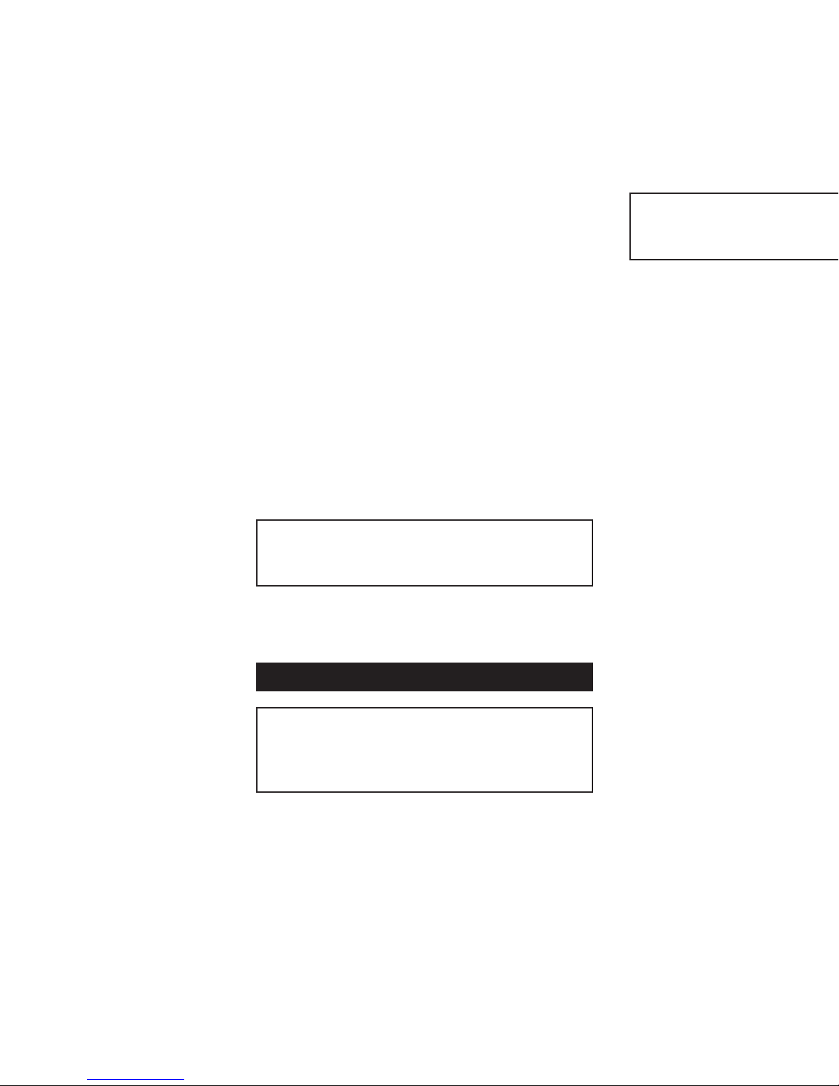
S t e e l C u t t i n g C i r c u l a r S a w
S e r v i c e P a r t s L i s t
EVO230-HDX
REV.
1.00
®
21
82
11
01
02
03
04
05
06
07
09
10A
99
80
08
2
3
82
14
12
13
15
60
96
68
17
16
19
72
18
71
70
2
42
62
94
2
62
83
86
27
24
4
25
26
91
2
39
37
2
30
31
32
41
40
33
43
34
2
36
28
29
49
47
24
2
46
2
38
2
48
2
2
2
2
112
116
2
111
109
110
108
2
67
115
2
62
73
2
51
114
53
2
57
54
55
2
56
59
62
2
60
87
82
88
121
96
97
50
2
2
35
52
60
61
64
74
76
75
77
78
79
81
84
83
92
121
121
1/3
1/3
1/3
1/3
2/3
118
117
22
120
119
23
76
Page 19

Nível de Vibração (Sob Carga) (m/s2): 3.9
Peso: 9kg
Dimensões Máximas ALP: 370x400x500
Dimensões Mínimas ALP: 250x325x500
Dimensões da Lâmina
Diâmetro Máximo: 230mm
Diâmetro de Perfuração: 25.4mm
Espessura: 2mm
Equipamento standard Fornecido com a unidade: 1 Manípulo lateral, 1
Guia de Protecção, 1 viseiras de protecção, 1 chave xa à unidade, 1
Mala de Transporte, 2 Baterias, Tampões para os Ouvidos, 1 Instruções
de Operação.
Durante o uso deste equipamento é OBRIGATÓRIA a utilização
de protecções para os olhos e os ouvidos. NÃO toque na lâmina
enquanto esta se encontrar em movimento. Durante o uso desta
ferramenta, siga sempre as recomendações do Equipamento para
Protecção Individual.
Esta máquina foi concebida para cortar aço utilizando as lâminas e
acessórios estelitados (com carboneto de tungsténio). NÃO deverá ser
modicada e/ou utilizada de alguma outra forma a não ser aquela para a
qual foi concebida, incluindo fornecer energia a outros equipamentos.
Assegure-se que pode ver na totalidade a área em que vai trabalhar
a partir do lugar onde se posiciona. Utilize barreiras para afastar as
pessoas. Não use esta ferramenta em ambientes onde existir o risco
de explosão - as ferramentas eléctricas podem produzir faulhas que
por sua vez podem incendiar materiais ou gases inamáveis. Devido
à possível ocorrência de choques eléctricos, não use esta ferramenta
em condições ou áreas húmidas ou molhadas. Quando manusear esta
ferramenta, use sempre as duas mãos. Assegure-se sempre que o
material em que está a trabalhar se encontra devidamente seguro.
• Este aparelho vem equipado de um cabo eléctrico e cha adequados
ao país de utilização.
• Retire a cha da tomada antes de efectuar a troca da lâmina, antes
de fazer alinhamentos ou outros serviços de reparação.
• Utilize apenas lâminas de cortar genuínas da EVOLUTION
• Inspeccione sempre a máquina e a lâmina antes de cada utilização,
e não use lâminas deformadas, com falhas, desgastadas ou
danicadas de qualquer outro modo.
• Assegure-se que a lâmina se encontra correctamente montada e é
adequada para o material a cortar.
• Não utilize aço para corte rápido
• Não utilize lâminas que não tenham as características especicadas
nestas instruções
• Não pare a lâmina aplicando pressão lateral sobre o disco.
• Assegure-se de que as protecções móveis funcionam livremente e
sem prender.
• Nunca utilize a ferramenta sem o sistema original de protecção.
Não tranque a protecção móvel na posição aberta.
• Mantenha sempre o cabo eléctrico afastado das partes móveis da
ferramenta.
• Quando arrumar a ferramenta , desligue o motor e assegure-se que
todas as partes móveis se encontram completamente paradas.
• No caso de encravamento, desligue a ferramenta imediatamente e
retire a cha da tomada.
• Antes de utilizar acessórios, compare sempre as rotações (RPM)
máximas permitidas para o acessório, com as rotações da
ferramenta.
• Assegure-se que o manípulo de ajuste de corte, o manípulo de
ajuste de ângulo e o manípulo lateral se encontram rmemente
xos enquanto utilizar a ferramenta (g. 1).
• Utilize apenas as anges e porcas fornecidas com a ferramenta, e
del alojamiento porta baterías e instale las baterías suministradas,
teniendo cuidado de observar la polaridad correcta, y reinstalando
luego la cubierta. Ponga el interruptor en la posición ON (conectada)
para activar, y recuerde de apagar el láser al nalizar el corte. Antes de
usarlo, el sistema de guía visual deberá alinearse mediante el tornillo
de ajuste. Aviso importante: No dirija el láser a personas ni mire
NUNCA directamente a la luz del láser, ya que de lo contrario podrá
sufrir graves daños en los ojos.
Recogida de virutas
Esta herramienta se suministra con un compartimiento colector de
virutas. Cuando las virutas llegan hasta la ventana transparente, retire la
cubierta para limpiarla y luego vuelva a instalarse apretando las perillas.
Aviso: Las virutas metálicas en el interior de la cubierta pueden estar
muy calientes y aladas; no las toque con las manos desnudas.
Mantenimiento y localización de averías
Mantenga limpios el cable y la herramienta. Evite usar productos de
limpieza que podrían incluir benceno, tricloroetileno y amoniaco ya que
pueden dañar las piezas de plástico. En caso de mal funcionamiento
eléctrico o mecánico, desactive inmediatamente la herramienta y retire
el enchufe. Un chisporroteo excesivo casi siempre indica la presencia
de suciedad en el motor o escobillas de carbón desgastadas. Verique
si hay desgaste y recambie cuando alcance 6mm. Lleve el equipo a
un centro de servicio autorizado para cualquier otro mantenimiento y
reparación.
Lubricación
La caja de engranajes de la máquina viene lubricada de fábrica. Para
revisar o/y agregar lubricante, es necesario desmantelar la herramienta.
Esta operación deberá hacerse siempre en el CENTRO DE SERVICIO
más cercano. Todas las reparaciones y los servicios realizados en estos
centros están totalmente garantizados contra materiales y mano de obra
defectuosos.
Accesorios – Cuchillas marca Evolution auténticas
40T Cuchilla para madera TCT de 230mm
48T Cuchilla para acero dulce TCT de 230mm
60T Cuchilla para acero inoxidable TCT de 230mm
80T Cuchilla para aluminio TCT de 230mm
Aviso: El desgaste normal y los daños causados por uso
incorrecto NO los cubre la garantía de 12 meses.
Instruções de Operação
Importante
Por favor leia estas instruções de operação e segurança com
atenção e na sua totalidade. Para sua segurança, antes de utilizar
este equipamento, verique se a voltagem de corrente eléctrica é
a correcta e que todos os manípulos e peças estão devidamente
seguros. Se tiver alguma dúvida acerca de qualquer um dos aspectos
da utilização deste equipamento, contacte o seu distribuidor.
Por Favor Guarde Estas Instruções
Especicações do modelo EVO230-HDX
Motor(230 ou 115v 50/60Hz)(Watts): 1750
Dimensões Máximas da caixa (parede de 6mm 90o): 84mm
Dimensões Máximas da caixa (parede de 6mm 45o): 53mm
Espessura Ideal de Corte (Placa de Aço Macio): 12mm
RPM sem carga (min-1): 2700
Tempo máximo de serviço recomendado (minutos): 30
Nível de pressão sonora (Sob Carga) (db(A): 108.7
18 17
Page 20

substitua-as caso sejam danicadas ou quem gastas.
Montagem da máquina
Montagem / Remoção das lâminas de corte estelitadas
Retire a tampa com recipiente de recolha de aparas da máquina
desapertando o botão. Desaperte os dois parafusos para libertar a
protecção interior da lâmina. Desaperte o parafuso que xa a chave à
máquina e remova-a. Desaperte o parafuso M13 que segura a lâmina
(g. 3) e remova a ange da lâmina. Nota: Use o fecho do eixo. Substitua
a lâmina certicando-se que a seta de direcção de rotação da lâmina se
encontra alinhada com a da máquina e em seguida aperte o parafuso
M13 com a ange na posição correcta. Nota: Assegure-se que o fecho
do eixo está completamente solto fazendo rodar a lâmina manualmente
antes do uso. Volte a colocar chave no suporte da máquina e aperte o
parafuso de xação.
Ajuste da profundidade do corte
Para conseguir a profundidade do corte desejada, solte o manípulo.
Assegure-se que a lâmina não se salienta mais do que 4mm do material
a ser cortado. Aperte bem o manípulo para trancar a posição. Nota: A
guia de protecção (g. 1) está marcada em intervalos de 0-84mm para
ajudá-lo a determinar a profundidade de corte.
Ajuste do Ângulo de Corte
Liberte ambos os manípulos de xação (g. 2) e faça o ajuste do
ângulo de corte desejado alinhando a marca com a escala impressa.
Aperte ambos os manípulos para trancar a posição. Nota: Existem
determinados cortes compostos em que poderá ser necessário retrair
manualmente a protecção da lâmina de modo a permitir que a lâmina
entre e/ou passe através do corte.
Alinhamento das Ranhuras de Orientação de Corte
Na parte frontal da base da serra poderá ver ranhuras de orientação.
A ranhura da esquerda é utilizada para seguir uma linha enquanto se
efectua um corte de 90 graus. A ranhura da direita é utilizada para seguir
uma linha enquanto se efectua um corte de 45 graus.
Conselhos sobre a utilização
Sempre que possível, xe a peça em que vai trabalhar com grampos
sobre um suporte rígido, tal como um banca de trabalho ou cavalette de
corte. Esta ferramenta vem equipada com um dispositivo de segurança
- para a ligar, tem de premir o interruptor na parte lateral do manípulo
com o polegar - poderá então activar o interruptor principal para ligar a
ferramenta. Não force a ferramenta – deixe que a velocidade da lâmina
de corte faça o trabalho. O desempenho do corte não melhora através
da aplicação de pressão adicional sobre a ferramenta, sendo reduzida a
duração da lâmina. Quando utilizar a guia paralela assegure-se que se
encontra em paralelo em relação à lâmina e não relativamente à base da
ferramenta pois, se for esse o caso, poderá danicar a lâmina e o motor.
Para posicionar a guia, desaperte os dois parafusos de xação e faça-a
deslizar para junto da parte lateral da peça em que está a trabalhar. Volte
a apertar os parafusos para xá-la na posição desejada. Antes de ligar
o motor, coloque a extremidade frontal da serra sobre a peça no local
correcto. Quando iniciar o corte, ajuste visualmente a linha de corte com
com a linha da guia de corte e tenha o cuidado de introduzir lentamente
a lâmina no material de modo a não danicar os dentes da mesma.
Utilize ambas as mãos para movimentar a serra através da peça.
Sistema de Orientação Visual Laser
Uma das funções adicionais desta máquina é o sistema de orientação
visual laser, que pretende servir apenas de orientação e não deveria
ser tido em conta para determinar a exactidão de um corte. Remova a
tampa do compartimento da bateria e coloque as baterias fornecidas
tendo o cuidado de observar a polaridade correcta; volte a colocar a
tampa. Para activar o laser, prima o interruptor para que que na posição
16 19
Page 21

de ligado, e lembre-se de o desligar quando terminar o corte. Antes de
começar, a mira deverá ser alinhada através do parafuso de ajuste.
Aviso Importante: Não aponte o laser para ninguém e NUNCA olhe
directamente para a luz do laser, poderá causar danos graves nos
olhos.
Recolha de Aparas
Esta ferramenta é fornecida com um compartimento de recolha de
aparas. Quando as aparas se acumularem até se poderem ver na janela
de visualização, remova a tampa, esvazie-a, volte a colocá-la e aperte
os botões. Atenção: As aparas de metal no interior da tampa podem
car muito quentes e ser muito aguçadas – não as toque com as mãos
desprotegidas.
Manutenção e Determinação da Causa de Problemas
Mantenha a ferramenta, o cabo de corrente e a mala de transporte
limpos e sem aparas. Evite a utilização de produtos de limpeza,
entre os quais a benzina, tricloroetileno, cloreto e amónia já que estes
produtos danicam o plástico. No caso de haver uma avaria eléctrica
ou mecânica, desligue imediatamente a ferramenta e retire a cha da
tomada. Demasiadas faulhas podem indicar a presença de sujidade no
motor ou o desgaste das escovas de carbono. Verique se há desgaste
e proceda à sua substituição quando alcançarem os 6mm. Para todos
as outras reparações leve a sua máquina ao seu distribuidor local, ou à
Evolution Power Tools USA, Iowa, caso tenha sido comprada nos EUA.
Lubricação
A caixa de engrenagens da sua máquina já vem lubricada de
fábrica. Para vericar o nível do lubricante ou adicionar, é necessário
desmontar a ferramenta. Esta operação deverá sempre ser efectuada
por um CENTRO DE SERVIÇO ou, caso se encontre nos EUA, pela
Evolution Power Tools EUA, Iowa. Todas as reparações e manutenções
efectuadas por estes serviços, são completamente garantidas contra
materiais e mão de obra defeituosos.
Acessórios – Lâminas Genuínas da Marca Evolution
40T 230mm TCT Lâmina para Madeira
48T 230mm TCT Lâmina de Aço Macio
60T 230mm TCT Lâmina de Capacidade para Aço Inoxidável
80T 230mm TCT Lâmina para Alumínio
Note: Os estragos normais causados por uma utilização incorrecta
da ferramenta NÃO são cobertos pela garantia de 12 Meses.
ΟΔΗΓΙΕΣ ΧΡΗΣΕΩΣ
Σημαντικό
Παρακαλούμε διαβάστε αυτές τις οδηγίες χρήσεως και
ασφαλείας προσεκτικά και πλήρως. Για τη δική σας ασφάλεια,
προτού χρησιμοποιήσετε αυτή τη συσκευή ελέγξατε ότι η
ηλεκτρική τάση είναι η σωστή και ότι όλες οι χειρολαβές
και τα εξαρτήματα είναι στέρεα προσαρμοσμένα. Εάν δεν
είστε βέβαιοι για οποιοδήποτε τμήμα αυτής της συσκευής
απευθυνθείτε στον αντιπρόσωπό σας
Παρακαλούμε κρατήστε αυτές τις οδηγίες
Μοντέλο EVO230-HDX Τεχνικά χαρακτηριστικά
Κινητήρας (230v ή 115v 50/60 Hz) (Watts): 1750
Μέγιστο Κιβώτιο (4mm Τοίχος 900) 84mm
Μέγιστο Κιβώτιο (4mm Τοίχος 450) 53mm
Ιδανικό Πάχος Κοπής Μέτριας Σκληρότητας Πλάκας Χάλυβα 12mm
Στροφές ανά λεπτό χωρίς φορτίο (ελαχ-1) 2700
Συνιστώμενος Μέγιστος Κύκλος Λειτουργίας (Λεπτά): 30
Régimen de trabajo máximo recomendado (minutos): 30
Nivel de presión acústica (bajo carga) (dB(A)): 108.7
Nivel de vibración (bajo carga)(m/s2): 3.9
Peso (kg.): 9.0
Dimensiones máximas (mm): A 370 An 400 P 500
Dimensiones mínimas (mm): A 250 An 325 P 500
Dimensiones de cuchilla
Diámetro máximo (mm): 230
Diámetro interior (mm): 25.4
Espesor (mm): 2
Equipo standard incluido con la herramienta: 1 asidero lateral, 1 guía
de guarda, 1 gafas protectoras, 1 llave de roscas de 13mm sujeta a la
herramienta, 2 baterias, 1 juego de auriculares de protección , 1 estuche
de transporte y estas Instrucciones de funcionamiento.
Al manejar esta herramienta DEBEN llevarse auriculares y gafas
de protección. NO tocar la disco mientras está en marcha.
Al manejar esta herramienta deben observarse siempre las
recomendaciones aplicables a equipos de protección personal.
Esta herramienta está diseñada para cortar acero usando cuchillas y
accesorios con TCT (borde de carburo al tungsteno) adecuados. NO
deberá ser modicada y / o usada para cualquier otra aplicación que no
sea la intencionada, incluido el accionamiento de otros equipos.
Asegure que toda la zona de trabajo pueda verse desde el punto
de manejo. Use barreras para mantener alejada a la gente. No use
la herramienta en entornos de trabajo explosivos; las herramientas
motorizadas crean chispas que pueden provocar la ignición de gases
o materiales inamables. No maneje la herramienta en lugares o
condiciones mojadas o húmedas, ya que pueden sufrirse sacudidas
eléctricas. Use siempre ambas manos para manejar la herramienta.
Verique siempre que el material de trabajo haya sido sujetado con
seguridad.
• Esta herramienta incorpora un cable y enchufe aprobados para el
país de uso intencionado.
• Retire el enchufe del suministro de la red antes de recambiar
la cuchilla, efectuar ajustes o cualquier otro trabajo de
mantenimiento.
• Recomendamos usar solamente cuchillas de sierre marca
EVOLUTION auténticas.
• Inspeccione la máquina y la cuchilla antes de cada uso y no utilice
cuchillas deformadas, agrietadas, gastadas o dañadas.
• Asegure que la cuchilla esté correctamente instalada y no la
detenga con la mano.
• No use cuchillas fabricadas con acero de corte rápido.
• No use cuchillas que no satisfacen las características especicadas
en estas instrucciones.
• No detenga la cuchilla con una presión lateral sobre el disco.
• No use cuchillas fabricadas con acero de corte rápido.
• No use cuchillas que no satisfacen las características especicadas
en estas instrucciones.
• No pare la cuchilla ejerciendo presión lateral sobre el disco.
• Asegure que las guardas móviles funcionen sin atascarse.
• No use nunca la herramienta sin el sistema de guarda
protectora original activado. No bloquee la guarda móvil en su
posición abierta.
• Mantenga siempre el cable eléctrico alejado de las piezas móviles
de la herramienta.
• Al guardar la herramienta, apague el motor y asegure que se han
parado por completo todas las piezas móviles.
• En caso de atasco, desactive inmediatamente la herramienta y
retire el enchufe.
• Antes de usar accesorios, compare siempre las máximas r.p.m.
20 15
Page 22

Importante
0
) (mm): 84
0
) (mm): 53
Επίπεδο Θορύβου με πίεση (Υπό φορτίο) (dB(A)): 108.7
Επίπεδο Δόνησης (Υπό Φορτίο) m/s2): 3.9
Βάρος: 9.0kg
Μέγιστες Διαστάσεις: 370x400x500
Ελάχιστες Διαστάσεις: 250x325x500
Διαστάσεις Λάμας
Μέγιστη Διάμετρος 230mm
Διάμετρος Βάσης Υποδοχής 25.4mm
Πάχος 2mm
Στάνταρτ Εξοπλισμός που παρέχεται μαζί με το εργαλείο: 1
Πλευρική Χειρολαβή, 1 Προστατευτικός Οδηγός, 1 ζευγάρι
προστατευτικά Γυαλιά, 1 Γαλλικό κλειδί προσαρμοσμένο
πάνω στο εργαλείο, 1 Βαλιτσάκι Μεταφοράς, 2 Μπαταρίες,
Ωτασπίδες, 1 Εγχειρίδιο Οδηγιών Χρήσης
Ωτασπίδες και προστατευτικά γυαλιά ΠΡΕΠΕΙ να
χρησιμοποιούνται όταν λειτουργείτε αυτή τη συσκευή. ΜΗΝ
ΑΓΓΙΖΕΤΕ τη λάμα όταν βρίσκεται σε κίνηση. Πάντοτε να
ακολουθείτε τις συστάσεις των Εξαρτημάτων Προσωπικής
Προστασίας (PPE) όταν λειτουργείτε αυτό το εργαλείο.
Αυτό το μηχάνημα είναι σχεδιασμένο για την κοπή χάλυβα
χρησιμοποιώντας τις κατάλληλες λάμες TCT ( Tungsten Carbide
Tipped) και εξαρτήματα. ΔΕΝ θα πρέπει να τροποποιείται και/ή
να χρησιμοποιείται για οποιαδήποτε άλλη εφαρμογή εκτός από
αυτήν την οποία προορίζεται, συμπεριλαμβανομένης και της
μετάδοσης κίνησης σε άλλες συσκευές.
Βεβαιωθείτε ότι όλος ο χώρος εργασίες μπορεί να είναι ορατός
από την θέση του χειρισμού. Χρησιμοποιείτε περιοριστικούς
φραγμούς για κρατάτε του μη έχοντας εργασία μακρά. Μην
λειτουργείτε το εργαλείο σε περιβάλλον με εκρηκτικά υλικά
–ηλεκτροκίνητα εργαλεία δημιουργούν σπινθήρες που μπορεί
να προκαλέσουν ανάφλεξη εύφλεκτων υλικών ή αερίων. Μην
λειτουργείτε το εργαλείο σε συνθήκες υγρές ή χώρους με αυξημένη
υγρασία καθώς μπορεί να προκληθούν ηλεκτροσόκ. Πάντοτε
να χειρίζεστε το εργαλείο και με τα δυο χέρα σας. Πάντοτε να
έχετε βεβαιωθεί ότι το υλικό επί του οποίου εργάζεστε είναι καλά
στερεωμένο.
• Το εργαλείο είναι εφοδιασμένο με ένα καλώδιο και
φις εγκεκριμένα από το κράτος όπου πρόκειται να
χρησιμοποιηθεί.
• Να βγάλετε το φις από την πρίζα προτού αντικαταστήσετε
τη λάμα, κάνετε ρυθμίσεις ή για οποιαδήποτε άλλη εργασία
συντήρησης.
• Να χρησιμοποιείτε μόνο τις γνήσιες λάμες πριονιού
EVOLUTION
• Επιθεωρήστε το μηχάνημα και τη λάμα πριν από κάθε
χρήση και να μην χρησιμοποιείτε τρυπάνια που έχουν
στραβώσει. έχουν ρωγμές, έχουν φθαρεί ή έχουν υποστεί
άλλη βλάβη.
• Βεβαιωθείτε ότι η λάμα είναι σωστά τοποθετημένη και ότι
είναι η κατάλληλη για το προς κοπή υλικό
• Μην χρησιμοποιείτε λάμες που είναι κατασκευασμένες από
χάλυβα υψηλής ταχύτητας
• Να μην χρησιμοποιείτε λάμες, τα οποία δεν είναι σύμφωνα
προς τεχνικά χαρακτηριστικά που καθορίζουν αυτές οι
οδηγίες χρήσεως.
• Μην σταματάτε τη λάμα με άσκηση πλευρικής πίεσης επί
του δίσκου.
• Βεβαιωθείτε ότι οι κινούμενοι προφυλακτήρες λειτουργούν
ελεύθερα χωρίς «κολλήματα»
• Μην χρησιμοποιείτε ποτέ το μηχάνημα χωρίς το
γνήσιο προστατευτικό του σύστημα. Μην
14 21
Page 23

ασφαλίζετε τον κινούμενο προφυλακτήρα στην ανοικτή
θέση.
• Πάντοτε να κρατάτε το καλώδιο μακριά από τα
μετακινούμενα μέρη του εργαλείου
• Όταν αφήνετε το εργαλείο, να σβήνετε τον κινητήρα και να
έχετε βεβαιωθεί ότι όλα τα εν κινήσει τμήματα έχουν τελείως
σταματήσει.
• Στην περίπτωση κολλήματος σβήστε αμέσως το εργαλείο και
αποσυνδέστε το από το ρεύμα.
•
Πριν χρησιμοποιήσετε τα εξαρτήματα να συγκρίνετε πάντοτε
τον μέγιστο επιτρεπτό αριθμό στροφών ανά λεπτό (RPM).
• Βεβαιωθείτε ότι η λαβή ρύθμισης του βάθους κοπής, η λαβή
ρύθμισης της γωνίας και οι πλευρικές χειρολαβές είναι καλά
στερεωμένες όταν χρησιμοποιείτε το εργαλείο (Εικόνα 1)
• Να χρησιμοποιείτε μόνο τις φλάντζες και τις ροδέλες που
παρέχονται με το εργαλείο και να τις αντικαθιστάτε όταν
παθαίνουν βλάβη ή κάνουν εγκοπές.
Εγκατάσταση του μηχανήματος
Συναρμολόγηση/Αφαίρεση των λαμών TCT του πριονιού.
Αφαιρέσατε το κάλυμμα του συλλέκτη ρινισμάτων από το
μηχάνημα, βγάζοντας τo κουμπί. Ξεβιδώστε τις δυο βίδες
για να απελευθερώσετε τον εσωτερικό προφυλακτήρα της
λάμας. Χαλαρώστε τη βίδα που κρατάει το γαλλικό κλειδί στο
μηχάνημα και αφαιρέστε το. Ξεβιδώστε το μπουλόνι Μ13 που
σταθεροποιεί τη λάμα (Εικόνα 3) και αφαιρέσατε την φλάντζα
της γκάμας. Σημείωση: Χρησιμοποιήστε ατρακτοειδές κλείστρο.
Αντικαταστήστε τη λάμα και βεβαιωθείτε ότι το βέλος για την
κατεύθυνση της περιστροφής της λάμας ταυτίζεται με αυτό του
μηχανήματος και στη συνέχεια σφίξτε το μπουλόνι Μ13 με τη
φλάντζα στη σωστή θέση. Σημείωση: Ελέγξατε ότι το ατρακτοειδές
κλείστρο έχει τελείως απελευθερωθεί. περιστρέφοντας με το
χέρι τη λάμα πριν τη χρησιμοποίησή της. Επαναπροσαρμόστε
το γαλλικό κλειδί στη λαβή επί του μηχανήματος και σφίξτε την
βίδα που το κρατάει.
Ρύθμιση του Βάθους Κοπής
Απελευθερώστε τη χειρολαβή για να ρυθμίσετε το απαιτούμενο
βάθος κοπής. Βεβαιωθείτε ότι η λάμα προεξέχει κατά το μέγιστο
4mm μέσω του υλικού προς κοπή. Σφίξτε τη χειρολαβή ώστε
να εφαρμόσει στη θέση τους. Σημείωση: Ο προφυλακτήρας
ασφαλείας (Εικόνα 1) είναι βαθμολογημένος με αυξανόμενες
ενδείξεις από 0-84mm για την υποβοήθηση της ρύθμισης του
βάθους κοπής.
Ρύθμιση της γωνίας κοπής
Απελευθερώσατε και τις δυο στερεωτικές χειρολαβές και ρυθμίστε
την απαιτούμενη γωνία κοπής ευθυγραμμίζοντας την ένδειξη με
την τυπωμένη κλίμακα. Σφίξτε και τις δυο χειρολαβές στη θέση
σταθεροποίησής τους. Σημείωση: Υπάρχουν συγκεκριμένες
σύνθετες κοπές στις οποίες μπορεί να χρειαστεί να αφαιρέσετε
με τα χέρια τον προφυλακτήρα, ώστε να επιτρέψετε στη λάμα να
εισχωρήσει εντός ή/ και δια μέσου της κοπής.
Γραμμή Κοπής με Αυλακώσεις Καθοδήγησης
Οι αυλακώσεις καθοδήγησης παρέχονται μπροστά από τη βάση
της λάμας. Η αριστερή αυλάκωση χρησιμοποιείται για την
ευθύγραμμη ακολουθία όταν γίνεται κοπή υπό γωνία 900 . Η δεξιά
αυλάκωση χρησιμοποιείται για την ευθύγραμμη ακολουθία όταν
γίνεται κοπή υπό γωνία 450.
Συμβουλές Χειρισμού
Πάντοτε να στερεώνετε το αντικείμενο εργασίας πάνω σε ένα
σκληρό στήριγμα όπως ένα πάγκο ή σε καβαλέτα πριονιού,
όπου αυτό είναι δυνατόν. Το εργαλείο είναι εξοπλισμένο με
ένα στοιχείο ασφαλούς έναρξης-για να ανάψετε το εργαλείο, θα
Sie die M13-Schraube, die das Sägeblatt (Abb. 3) sichert und entfernen
Sie den Sägeblattansch. Hinweis: Benutzen Sie die Spindelarretierung.
Setzen Sie das neue Sägeblatt ein und achten Sie darauf, dass der
Drehrichtungspfeil auf dem Sägeblatt mit der Drehrichtung des Gerätes
übereinstimmt und ziehen Sie anschließend die M13-Schraube mit dem
Flansch in der korrekten Position an. Hinweis: Kontrollieren Sie, dass
die Spindelarretierung vollständig gelöst ist, indem Sie das Sägeblatt
vor der Benutzung des Gerätes mit der Hand drehen. Stecken Sie den
Schraubenschlüssel wieder in die Halterung am Gerät und ziehen Sie
die Halteschraube an.
Schnitttiefe einstellen
Lösen Sie den Griff, um die gewünschte Schnitttiefe einzustellen. Achten
Sie darauf, dass das Sägeblatt maximal 4mm aus dem zu schneidenden
Material herausragt. Den Griff wieder anziehen, um das Sägeblatt in
dieser Position zu arretieren. Hinweis: Auf der Schutzhaube (Abb. 1)
sind Markierungen von 0 – 84mm angebracht, um das Einstellen der
Schnitttiefe zu erleichtern.
Schnittwinkel einstellen
Lösen Sie beide Arretiergriffe (Abb. 2) und stellen Sie den gewünschten
Schnittwinkel ein, indem Sie das Sägeblatt mit der Markierung auf
der abgedruckten Skala ausrichten. Beide Griffe wieder anziehen,
um das Sägeblatt in dieser Position zu arretieren. Hinweis: Bei
bestimmten Kombinationsschnitten muss die Schutzvorrichtung manuell
zurückgezogen werden, damit das Sägeblatt in den Schnitt eindringen
und/oder durch den Schnitt geführt werden kann.
Führungsschlitze für die Schnittlinie
An der Vorderseite der Fußplatte des Gerätes benden sich
Führungsschlitze. Der linke Schlitz wird benutzt, um einer Linie bei
einem 90-Grad-Schnitt zu folgen. Der rechte Schlitz wird benutzt, um
einer Linie bei einem 45-Grad-Schnitt zu folgen.
Ratschläge zur Bedienung
Wo möglich sollten Sie das Werkstück immer fest einspannen,
beispielsweise in eine Werkbank oder zwischen Sägeböcken. Dieses
Elektrowerkzeug ist mit einer Anlaufsicherung ausgestattet. Um
das Gerät zu starten, müssen Sie zuerst den seitlich am Handgriff
angebrachten Schalter mit dem Daumen nach vorn schieben. Dann
auf den Hauptschalter drücken, um den Motor einzuschalten. ÜbenSie
keinen übermäßigen Druck auf das Gerät aus, lassen Sie das Sägeblatt
die Arbeit erledigen. Die Schnittleistung wird durch mehr Druck auf
das Gerät nicht verbessert, dies reduziert jedoch die Lebensdauer
des Sägeblatts. Beim Arbeiten mit dem Parallelanschlag darauf
achten, dass dieser parallel zum Sägeblatt ist und nicht zum Fuß des
Elektrowerkzeugs, da Sägeblatt und Motor sonst beschädigt werden
könnten. Zum Einstellen des Anschlags die beiden Halteschrauben
lösen und den Anschlag eng gegen die Seite des Werkstücks schieben.
Anschließend die Schrauben wieder anziehen, um den Anschlag in der
gewünschten Position zu sichern. Bringen Sie die Vorderkante der Säge
rechtwinklig auf das Werkstück, bevor Sie den Motor einschalten. Bringen
Sie vor dem Schneiden die Schnittlinie mit der Schnittlinienführung in
eine Linie und führen Sie das Sägeblatt langsam in das Werkstück ein,
um eine Beschädigung der Sägeblattzähne zu vermeiden. Schieben Sie
die Säge mit beiden Händen vorwärts durch das Werkstück.
Laserzielsystem
Ein zusätzliches Leistungsmerkmal dieses Gerätes ist das
Laserzielsystem, das jedoch nur als Hilfsmittel gedacht ist. Verlassen
Sie sich hinsichtlich der Genauigkeit eines Schnitts nicht auf dieses
System. Nehmen Sie den Deckel des Batteriefachs ab und legen Sie
die im Lieferumfang enthaltenen Batterien ein. Dabei auf korrekte
Polarität achten. Anschließend den Deckel wieder auegen. Schieben
Sie den Schalter in die Stellung Ein, um das System einzuschalten
und vergessen Sie nicht den Laser nach dem Schnitt wieder
22 13
Page 24

Verletzungen.
πρέπει αρχικά να πιέσετε το διακόπτη στα πλάγια της χειρολαβής
με τον αντίχειρά σας-μετά μπορείτε να πιέσετε τον κύριο
διακόπτη δίκην σκανδάλης για να λειτουργήσετε τον κινητήρα.
Μην πιέζετε το εργαλείο-αφήστε την ταχύτητα της λάμας του
πριονιού να κάνει τη δουλειά. Η απόδοση κοπής δεν θα βελτιωθεί
με την εφαρμογή περισσότερης πίεσης στο εργαλείο και η
διάρκεια ζωής της λάμας θα μειωθεί. Όταν χρησιμοποιείτε τον
παράλληλο οδηγό βεβαιωθείτε ότι είναι παράλληλος με την λάμα
και όχι με τη βάση του εργαλείου καθώς διαφορετικά η λάμα
και ο κινητήρας μπορεί να υποστούν βλάβη. Για να ρυθμίσετε
τον οδηγό, χαλαρώστε τις δυο βίδες σταθεροποίησής του και
γλιστρήστε άνετα προς τα πάνω ενάντια προς την πλευρική
επιφάνεια του αντικειμένου εργασίας. Σφίξτε πάλι τις βίδες για
να τον σταθεροποιήσετε στην επιθυμητή θέση. Τοποθετήστε
το πρόσθιο άκρο του πριονιού καθέτως επί του αντικειμένου
εργασίας πριν ανάψετε τον κινητήρα. Όταν αρχίζετε μια κοπή,
σημαδέψτε την γραμμή κοπής με ην γραμμή κοπής του οδηγού,
φροντίζοντας να εισάγετε τη λάμα στο υλικό αργά έτσι ώστε
να μην υποστούν ζημιά τα δόντια. Χρησιμοποιήστε και τα δυο
χέρια για να μετακινήσετε το πριόνι προς τα εμπρός μέσω του
αντικειμένου εργασίας.
Σύστημα Οδηγού με Ρύθμιση Λέιζερ
Ένα πρόσθετο χαρακτηριστικό του μηχανήματος είναι το
σύστημα ρύθμισης (στόχευσης) με λέιζερ το οποίο προορίζεται
μόνο σαν οδηγός και δεν θα πρέπει να βασίζεται η ακρίβεια
μιας κοπής σε αυτό. Αφαιρέσατε το κάλυμμα του χώρου
της μπαταρίας και τοποθετήστε τις παρεχόμενες μπαταρίες,
φροντίζοντας να προσέξετε τη σωστή πολικότητα και στη
συνέχεια επανατοποθετήστε το κάλυμμα. Πιέστε τον διακόπτη
στη θέση «on» για να ενεργοποιήσετε και θυμηθείτε να σβήσετε
το λέιζερ όταν έχετε τελειώσει την κοπή. Πριν από την χρήση η
ρύθμιση της ευθυγράμμισης πρέπει να γίνει ρυθμίζονται τις βίδες.
Σημαντική Ειδοποίηση: Μην σημαδεύετε το λέιζερ σε κανέναν
και ΠΟΤΕ να μην κοιτάτε απευθείας στην ακτίνα του λέιζερ,
καθώς αυτό μπορεί να προκαλέσει σοβαρή βλάβη στα μάτια.
Συλλογή Ρινισμάτων
Το εργαλείο είναι εφοδιασμένο με ένα διαμέρισμα συλλογής
ρινισμάτων. Όταν τα ρινίσματα αθροίζονται και φθάνουν
να φαίνονται από το παραθυράκι, αφαιρέσατε το κάλυμμα,
καθαρίστε το και επανατοποθετήστε το κάλυμμα, σφίγγοντας
στη συνέχεια τα κουμπιά. Σημείωση: Τα μεταλλικά ρινίσματα
μέσα στο κάλυμμα μπορεί να είναι πολύ ζεστά και αιχμηρά –μην
τα αγγίζετε με γυμνά χέρια.
Συντήρηση και Μηχανικές Βλάβες
Διατηρείτε το εργαλείο, το καλώδιο και το βαλιτσάκι μεταφοράς
καθαρά και ελεύθερα από ρινίσματα. Αποφεύγετε την χρήση
καθαριστικών προϊόντων στα οποία περιλαμβάνονται βενζίνη,
τριχλωροαιθυλένιο, χλώριο και αμμωνία καθώς αυτά μπορεί να
προκαλέσουν ζημία στα πλαστικά μέρη. Σε περίπτωση μηχανικής
ή ηλεκτρικής δυσλειτουργίας σβήστε αμέσως το εργαλείο και
αποσυνδέστε το από το ρεύμα. Υπερβολικοί σπινθήρες μπορεί
να αποτελούν ένδειξή ρύπων στον κινητήρα ή φθορά στα
καρβουνάκια. Ελέγξατε για τυχόν φθορά και αντικαταστήσατέ
τα όταν φθάσουν στα 6mm. Για οποιαδήποτε άλλη επισκευή
πηγαίνετέ το στον τοπικό αντιπρόσωπό σας ή στο Evolution
Power Tools USA, Iowa, εάν το φέρετε στις ΗΠΑ.
Λίπανση
Το μηχάνημά σας έχει λιπανθεί στο εργοστάσιο με αρκετό
λιπαντικό. Για να ελέγξετε και/ ή να προσθέσετε λιπαντικό
είναι απαραίτητο να αποσυναρμολογήσετε το εργαλείο. Αυτή η
εργασία πρέπει να γίνει από το πλησιέστερο ΚΕΝΤΡΟ ΣΕΡΒΙΣ
ή από την Evolution Power Tools USA, Iowa, εάν βρίσκεστε στις
12 23
Page 25

ΗΠΑ> Όλες οι επισκευές και το σέρβις που γίνεται από αυτά τα
κέντρα είναι πλήρως εγγυημένα έναντι ελαττωματικών υλικών
και εργασίας.
Εξαρτήματα –Γνήσιες Λάμες “Evolution”
40Τ 230mm TCT Λάμα Ξύλου
48Τ 230mm TCT Λάμα Μαλακού Χάλυβα
60Τ 230mm TCT Λάμα με Δυνατότητα Ανοξείδωτου Χάλυβα
80Τ 230mm TCT Λάμα Αλουμινίου
Ειδοποίηση : Φυσιολογική φθορά και βλάβη που προκαλείται
από κακό χειρισμό δεν καλύπτεται από την εγγύηση των 12
μηνών
Istruzioni d’uso
IIMPORTANTE!
Leggere attentamente e integralmente le istruzioni d’uso. Per la vostra sicurezza, prima di iniziare ad operare controllare che la tensione
dell’eletttroutensile sia corretta e che manopole e comandi siano integri. In caso di dubbio su ogni aspetto dell’uso di questo elettroutensile contattare il distributore.
Conservare queste istruzioni d’uso a portata di mano per ulteriori
consultazioni.
Caratteristiche Tecniche EVO230-HDX
Tensione: 220 Volt
Potenza assorbita: 1750 Watt
Capacità max taglio scatolato da 6 mm a 90°: 84 mm
Capacità max taglio scatolato da 6 mm a 45°: 53 mm
Spessore ottimale di taglio (lamiera acciaio): 12 mm
Velocità a vuoto: 2700 g/m
Duty Cycle: 30 min.
Pressione sonora: 108.7 DbA
Livello di vibrazione: 3.9 m/s²
Peso: 9.0 kg
Dimensioni max: 370x400x500
Dimensioni min: 250x325x500
Dimensioni lama
Diametro max: 230 mm
Diametro foro: 25.4 mm
Spessore: 2.0 mm
La fornitura comprende: 1 manopola laterale, 1 guida laterale, occhiali di
protezione, 1 chiave di servizio, 1 valigetta, 2 batterie, 2 tappi per orecchie, 1 manuale di istruzione.
NORME DI SICUREZZA
Occhiali di protezione e tappi per le orecchie DEVONO essere
utilizzati lavorando con questo elettroutensile. NON TOCCARE la
lama quando è in movimento. Seguire scrupolosamente le norme
vigenti sulla sicurezza sul lavoro durante l’utilizzazione di questo
elettroutensile.
Questo elettroutensile è stato progettato per tagliare acciaio e altri metalli utilizzando lame TCT, Tungsten Carbide Tipped (lame al Carburo di
Tungsteno con denti riportati). NON può essere modicato e/o utilizzato
per applicazioni diverse da quella per cui è stato progettato, ivi compreso
la sua utilizzazione con utensili diversi da quelli indicati.
Assicurarsi che l’area di lavoro sia completamente visibile dalla postazi-
Entretien et dépannage
Garder l’outil et le câble d’alimentation propres. Ne pas utiliser des
nettoyants à base de benzène, trichloroéthylène, chloride et ammoniac
puisqu’ils peuvent endommages les pièces en plastique. Mettre l’outil
immédiatement hors marche et hors tension en cas d’un mauvais
fonctionnement électrique ou mécanique. Un jaillissement d’étincelles
indique en général la présence d’impuretés dans le moteur ou des balais
en charbon usés. Vérier l’usure des balais en charbon et remplacer
lorsqu’ils ont une épaisseur de 6 mm. Apporter la scie à un centre de
réparation accrédité pour toute autre réparation ou entretien.
Lubrication
La boîte de vitesse de votre machine a été lubriée à l’usine. Pour verier
le lubriant et / ou en ajouter, il est nécessaire de démonter l’outil. Le
démontage doit toujours être effectué par le CENTRE DE SERVICE
ACCREDITE le plus proche. Les réparations et l’entretien effectués par
ces centres sont entièrement garantis contre les vices de fabrication et
de matériaux.
Accessoires – Lames de la marque Evolution
40T 230 mm lame en carbure pour bois
48T 230 mm lame en carbure pour acier doux
60T 230 mm lame en carbure pour acier inoxydable
80T 230 mm lame en carbure pour aluminium
Nota : L’usure excessive et les dommages provoqués par une
utilisation anormale ne sont pas couverts par la garantie de 12
mois.
Bedienungsanleitung
Wichtig
Bitte lesen Sie die Bedienungsanleitung und die Sicherheitshinweise
vollständig. Zu Ihrer Sicherheit, überprüfen Sie bitte vor jeder
Benutzung, dass die Spannung der Stromquelle mit den Angaben
auf dem Typenschild des Gerätes übereinstimmt, und dass alle
Handgriffe und Geräteelemente sicher montiert sind. Sollten Sie zu
irgendeinem Aspekt der Bedienung dieses Gerätes Fragen haben,
wenden Sie sich bitte an Ihren Händler.
Diese Bedienungsanleitung bitte aufbewahren
Technische Daten, Modell EVO230-HDX
Motor (230v oder 115v 50/60 Hz) (Watt): 1750
Maximale Kastenschnittleistung (6mm Wand 900) (mm): 84
Maximale Kastenschnittleistung (6mm Wand 450) (mm): 53
Maximale Schnittdicke (Weichstahlblech) (mm): 12
Leerlaufdrehzahl (min-1): 2700
Empf. Höchstdauer für ununterbrochenen Betrieb (Minuten):
30
Schalldruckpegel (unter Last) (dB(A)): 108.7
Vibrationspegel (unter Last) (m/s2): 3.9
Gewicht (kg): 9.0
Maximale Abmessungen (mm): H 370 B 400 T 500
Mindestabmessungen (mm): H 250 B 325 T 500
Sägeblatt
Maximaler Durchmesser (mm): 230
Aufnahmebohrungsdurchmesser (mm): 25.4
Dicke (mm): 2
Im Lieferumfang des Gerätes enthaltene Standardausrüstung: 1
seitlicher Handgriff, 1 Führungsanschlag, 1 Schutzbrille, 1 am Gerät
befestigter Schraubenschlüssel, 1 Tragekoffer, 2 Batterien, Ohrstöpsel
und diese Bedienungsanleitung.
24 11
Page 26

one in cui si opera. Utilizzare opportuni sbarramenti per i non addetti ai
lavori. Non utilizzare l’elettroutensile in aree a rischio di esplosione: le
scintille generate potrebbero innescare incendi o esplosioni di sostanze
o gas inammabili. Non utilizzare l’elettroutensile in aree bagnate o in
condizioni di alta umidità per evitare il rischio di cortocircuiti. Utilizzare
l’elettroutensile operando sempre con entrambe le mani. Assicurarsi
sempre che il materiale da tagliare sia opportunamente ssato.
• Questo elettroutensile è equipaggiato con cavo di alimentazione e
spina adatti alle normative del vostro paese.
• Staccare sempre la spina prima di cambiare la lama, effettuare
regolazioni o qualsiasi intenvento di manutenzione.
• Utilizzare esclusivamente lame originali Evolution.
• Controllare l’elettroutensile e la lama prima di ogni lavoro e non
• utilizzare lame deformate, crepate, consumate o in qualche
modo danneggiate.
• Non utilizzare lame in acciaio rapido.
• Non utilizzare lame che non corrispondano alle caratteristiche
indicate in queste istruzioni.
• Non bloccare la lama con la pressione laterale sul disco.
• Assicurarsi che le protezioni mobili operino correttamente senza
intoppi.
• Non utilizzare mai l’elettroutensile senza i dispositivi di protezione.
• Non bloccare le protezioni in posizione aperta.
• Tenere il cavo di alimentazione lontano dalle parti in movimento
dell’elettroutensile.
• Prima di riporre l’elettroutensile controllare che l’interruttore sia
spento e vericare che le parti in movimento siano effettivamente
ferme.
• In caso di bloccaggio spegnere immediatamente l’elettroutensile e
staccare il cavo di alimentazione.
• Prima di utilizzare qualsiasi accessorio controllare che la velocità
max consentita corrisponda alla velocità max dell’elettroutensile.
• Utilizzare esclusivamente rondelle e ange originali fornite con
l’elettroutensile e sostituirle se danneggiate.
• Assicurarsi che la manopola di regolazione della profondità di
taglio, la manopola della regolazione dell’inclinazione e la mano
pola laterale siano serrate a fondo. (vedi gura qui di seguito)
MESSA IN FUNZIONE
Montaggio/Smontaggio lama
Rimuovere dall’elettroutensile il coperchio del comparto per la raccolta
trucioli girando la manopola. Svitare il bullone M13 di bloccaggio della
lama e rimuovere la angia di bloccaggio come indicato in gura: Attenzione: eliminare con uno straccio pulito eventuali residui oleosi sulla
angia; bloccare il movimento dell’albero motore. Inserire la lama vericando che la freccia che indica la rotazione della lama corrisponda al
senso di rotazione della freccia dell’elettroutensile. Inserire la angia in
posizione corretta e serrare a fondo il bullone di bloccaggio. Attenzione:
rilasciare la leva di bloccaggio dell’albero posizionandola come indicato
vericando che il movimento della lama sia perfettamente libero ruotandola manualmen te come indicato in gura:
Regolazione angolo di taglio
Rilasciare entrambe le manopole di bloccaggio della guida come
indicato in gura: e regolare l’inclinazione come desiderato allineando
la tacca alla scala graduata. Serrare a fondo entrambe le manopole. Attenzione: il taglio di materiali compositi potrebbe richiedere di sollevare
manualmente la guida per consentire alla lama di mordere efcacemente il pezzo ta tagliare.
Linea di taglio
Sul fronte dell’elettroutensile sono riportate due tacche per indicare la
linea di taglio rispettivamente per tagli a 90° e 45°
10 25
Page 27

NORME DI UTILIZZO IMPORTANTI
Assicurare sempre con morsetti o simili su un piano rigido, banco da
lavoro o cavalletto il pezzo da tagliare. Questo elettroutensile è equippaggiato con un pulsante di avviamento di sicurezza: per poter operare
premere col pollice il pulsante sulla destra dell’impugnatura e successivamente azionare il comando a grilletto.
IMPORTANTISSIMO: assolutamente non forzare l’elettroutensile in
fase di taglio: far lavorare la lama alla sua velocità naturale e lasciare che sia lei a fare il lavoro! L’eccessiva pressione riduce la vita
della lama e del motore e NON migliora le prestazioni.
Attenzione: rilasciare la leva di bloccaggio dell’albero vericando che il
movimento della lama sia perfettamente libero ruotandola manualmente,
come indicato in gura: Reinserire la chiave di servizio nel suo alloggiamento e bloccarla con la vite.
Regolazione profondità di taglio
Rilasciare la manopola per la regolazione come in dicato in g. 1. Assicurarsi che la lama non fuoriesca più di 4 mm rispetto al materiale da
tagliare. Allo scopo di facilitare la regolazione la guida è contrasseganta
in incrementi da 0 a 84 mm. Utilizzando la guida laterale assicurarsi che
sia perfettamente parallela alla lama e non alla base dell’elettroutensile.
Il mancato allineamento provoca l’usura eccessiva della lama e può danneggiare il motore. Per regolare la guida allentare le due viti di bloccaggio ed appoggiarla con attenzione al bordo del materiale da tagliare;
quindi serrare le viti di bloccaggio nella posizione desiderata. Prima di
effettuare un taglio posizionare sempre il fronte dell’elettroutensile perfettamente allineato al pezzo da tagliare. Prima di iniziare a tagliare veri-
canre la posizione di taglio mediante la tacca apposita (90° o 45°) e
traguardare la linea di taglio usando il raggio LASER. Appoggiare la lama
dolcemente al materiale da tagliare in modo da non danneggiare i denti.
Lavorare sempre con entrambe le mani.
Sistema di guida LASER
Questo elettroutensile è fornito di un sistema di guida a raggio LASER
che è da intendersi come semplice guida per il taglio e su cui non ci si
può basare per la precisione del lavoro. Inserire le batterie fornite con la
macchina sollevando lo sportello del vano apposito e vericando la corretta polarità; quindi riposizionare lo sportello chiudendo il vano batterie.
Attivare il raggio posizionando l’interruttore in posizione ON. Ricordarsi
di spegnere il raggio dopo il taglio. Effettuare la regolazione del raggio
mediante la vite apposita prima di effettuare il taglio
AVVERTENZA IMPORTANTE: Non puntare MAI il raggio verso le
persone e non guardare MAI il raggio: questo potrebbe causare
gravissimi danni alla vista.
Raccolta sfridi
Questo elettroutensile è fornito di un vano per la raccolta degli sfridi.
Vericare il livello degli sfridi accumulati attraverso l’apposita nestrella
trasparente; rimuovere il coperchio per svuotare il vano porta sfridi e
riposizionare il coperchio avendo cura di stringere la manopola a vite.
Attenzione: la temperatura degli sfridi metallici può essere molto elevata: non manipolarli senza guanti di protezione.
Manutenzione e controlli
Curare la pulizia dell’elettroutensile, del cavo di alimentazione e della
valigetta rimuovendo ogni residuo di sfridi. Evitare l’uso di prodotti de-
tergenti che contengano benzene, tricloetilene, cloruri e ammoniaca, in
quanto potrebbero danneggiare le parti in plastica. In caso di malfunzionamenti elettrici o meccanici spegnere immediatamente l’elettroutensile e
scollegare la spina. La produzione eccessiva di scintille può essere segno di sporcizia nel motore o di carboncini consumati. Controllare lo stato
dei carboncini e sostituirli quando raggiungono la lunghezza di 6 mm.
Diamètre maxi (mm): 230
Diamètre d’alésage (mm): 25.4
Epaisseur (mm): 2
La scie est livrée en standard avec : 1 poignée latérale, 1 guide de
refend, 1 paire de lunettes de protection, 1 clé montée sur la scie, 1
coffret, 2 batteries, des protecteurs anti-bruit et le mode d’emploi.
Les protecteurs anti-bruit et les lunettes de protection DOIVENT
être portés lors de l’utilisation de la scie. NE PAS toucher la lame
en mouvement. Toujours suivre les consignes de protection
individuelle lors de l’utilisation de l’outil.
La scie a été conçue pour couper de l’acier à l’aide de lames en carbure
et des accessoires. La scie NE PEUT être modiée et/ou utilisée
pour des applications autres que celles recommandées, y compris
l’alimentation d’autres outils.
S’assurer que la zone de travail est entièrement visible du côté opérateur.
Utiliser des écrans pour tenir les personnes à l’écart. Ne pas utiliser
l’outil dans un environment explosif - les outils motorisés produisent des
étincelles qui peuvent allumer des substances ou des gaz inammables.
Ne pas utiliser l’outil dans un environnement humide puisque ceci peut
provoquer des chocs électriques. Toujours utiliser l’outil à deux mains.
Toujours s’assurer que la pièce à découper est bien serrée.
• Cet outil est équipé d’un câble d’alimentation et d’une che
approuvés pour le pays d’utilisation.
• Débrancher la scie du secteur avant le remplacement de la lame, le
réglage ou d’autres travaux d’entretien.
• N’utiliser que des lames de scie de la marque EVOLUTION.
• Inspecter la scie et la lame avant chaque utilisation et ne pas
utiliser des lames déformées, ssurées, usées ou endommagées.
• S’assurer que la lame est montée correctement et convient au
matériau à découper.
• Ne pas utiliser des lames en acier rapide.
• Ne pas utiliser des lames qui ne répondent pas aux spécications
du mode d’emploi.
• Ne pas arrêter la lame en exerçant une pression latérale sur le
disque.
• S’assurer que les carters mobiles peuvent fonctionner sans
bloquer.
• Ne jamais utiliser l’outil sans les carters de protection
d’origine. Ne pas verrouiller le carter mobile dans la position
ouverte.
• Toujours écarter le câble d’alimentation des pièces en mouvement
de l’outil.
• Mettre hors marche le moteur et s’assurer que toutes les pièces en
rotation se sont arrêtées complètement avant de ranger l’outil.
• Immédiatement mettre l’outil hors marche et débrancher la che en
cas de blocage.
• Avant d’utiliser les accessoires il faut toujours vérier si les
tours par minute de l’accesoire et les tours par minute de l’outil
correspondent.
• S’assurer que le bouton de réglage de la profondeur de coupe, le
bouton de réglage d’angle et la poignée latérale sont bien serrés
lors de l’utilisation de l’outil (Fig. 1).
• N’utiliser que les brides et les rondelles livrées avec l’outil et les
remplacer lorsqu’elles sont endommagées ou rainées.
Installation de la scie
Montage / démontage des lames en carbure de tungstène
Retirer le capot récupérateur copeaux de la machine en desserrant le
bouton. Dévisser les deux vis an de pouvoir retirer le protège-lame.
Desserrer la vis qui xe la clé sur la scie et retirer la clé. Desserrer la
boulon M13 qui xe la lame (Fig. 3) et retirer la bride de la lame. Nota
26 9
Page 28

8
Important
0
) (mm): 84
0
) (mm): 53
2
): 3.9
Per qualsiasi altro intervento di manutenzione rivolgersi al Distributore.
Lubricazione
La scatola ingranaggi del vostro elettroutensile è lubricata all’atto della
produzione. Per controllare e/o aggiungere lubricante è necessario
smontare l’elettroutensile. L’operazione deve essere effettuata dal centro
di manutenzione indicato dal Distributore. Ogni intervento di manutenzione effettuato da un centro autorizzato è coperto da garanzia per materiali difettosi e manodopera.
Accessori - Lame Evolution originali
40T 230mm Rossa 40 denti Lama TCT legno
48T 230mm Blu 48 denti Lama TCT acciaio
60T 230mm Gialla 60 denti Lama TCT inox
80T 230mm Verde 80 denti Lama TCT alluminio
Attenzione: L’usura normale, le rotture e i danni causati da utilizzo
improprio NON sono coperti dalla garanzia di 12 mesi.
27
Page 29

ENVIRONMENTAL PROTECTION
Recycle unwanted materials instead of disposing of them
as waste. All tools, hoses and packaging should be sorted,
taken to the local recycling center and disposed of in an
environmentally safe way.
Recyclable Materials Analysis List
Material Weight(Kg) Percentage (%)
Aluminum
Cast Iron
Iron Plate
Plastics
Others
Total
1.94
0.0
3.61
1.96
0.10
7.61
25.40%
0.00%
47.00%
25.70%
1.30%
Major Packaging Materials
Material Weight(Kg)
Carton
Polystyrene
Plastic
Polypropylene
Others
Total
1.23
0.0
4.50
0.001
0.0
5.731
UMWELTSCHUTZ
Recyceln Sie unbrauchbare Materialen nicht mit dem
normalen Restmüll. Alle Geräte, Kabel und Verpackungen
sollten sortiert und auf eine umweltfreundliche Art entsorgt
und recycelt werden.
Liste für recyclebare Materialien
Material Gewicht (Kg) Anteil in (%)
Aluminium
Gusseisen
Metallplatten
Plastik
Andere
Gesamt
1.94
0.0
3.61
1.96
0.10
7.61
25.40%
0.00%
47.00%
25.70%
1.30%
Hauptmaterialien der Verpackung
Material Gewicht (Kg)
Karton
Styropor
Weiche Kunststoffe
Kunststoffe
Andere
Gesamt
1.23
0.0
4.50
0.001
0.0
5.731
PROTECTION DE L’ENVIRONNEMENT
Recyclez les matières usées ou indésirables au lieu de
les jeter. Tous les outillages, composants et emballages
doivent être collectés, et déposés au centre de recyclage
local pour préserver l’environnement.
Liste analytique des matières recyclables
Matière Poids (Kg) Pourcentage ( % )
Aluminium
Fonte
Fer
Plastiques
Autres
Total
1.94
0.0
3.61
1.96
0.10
7.61
25.40%
0.00%
47.00%
25.70%
1.30%
Composants majoritaires des emballages
Matière Poids (Kg)
Carton
Polystyrène
Polyéthylene basse densité
Polypropylène
Autres
Total
1.23
0.0
4.50
0.001
0.0
5.731
Installatie van zaag
Montage / demontage van hardmetalen zaagblad
Verwijder het deksel van de spaanafzuiger van de zaag door de knop los
te draaien. Draai de twee schroeven los om de binnenste beschermkap
van het zaagblad te verwijderen. Draai de schroef los waarmee de
moersleutel op de zaag is vastgezet en verwijder de moersleutel. Draai
de M13 bout los waarmee het zaagblad (g. 3) is vastgezet en verwijder
de ens van de zaag. N.B.: Gebruik de asvergrendeling. Vervang het
zaagblad en zorg ervoor dat de pijl van de rotatierichting van het zaagblad
overeenkomt met de pijl op de zaag en draai hierna de M13 bout met
de ens op de juiste plaats vast. N.B.: Verieer of de asvergrendeling
uitgeschakeld is door het zaagblad voor het gebruik met de hand te
draaien. Monteer de sleutel opnieuw in de houder op de zaag en draai
de borgschroef vast.
Afstellen van zaagdiepte
Draai de hendel los om de juiste zaagdiepte in te stellen. Zorg ervoor dat
het zaagblad maximaal 4 mm boven het te zagen materiaal uitsteekt.
Draai de hendel vast. N.B.: De beschermkap (g. 1) is voorzien van
incrementen van 0 tot 84 mm om het afstellen van de zaagdiepte te
vergemakkelijken.
Schuininstelling
Draai beide vergrendelingen (g. 2) los en stel de juiste hoek in door
de merkstreep met de graadverdeling uit te lijnen. Draai beide hendels
opnieuw vast. N.B.: Bij bepaalde samengestelde zaagsneden kan het
nodig zijn om de beschermkap met de hand terug te trekken zodat het
zaagblad in en/of door de snede geïntroduceerd kan worden.
Zaaglijn geleidegleuven
De voorkant van de zaagzool is voorzien van geleidegleuven. De
linkergleuf wordt gebruikt om een zaaglijn bij een zaagsnede van
90° te volgen. De rechtergleuf wordt gebruikt om een zaaglijn bij een
versteksnede van 45° te volgen.
Bedieningsvoorschriften
Het werkstuk altijd op een onbuigzaam steunstuk zoals een werkbank of
zaagbok vastklemmen indien mogelijk. Het gereedschap is voorzien van
een startbeveiliging – om het gereedschap te starten moet u eerst op de
schakelaar op de zijkant van de hendel drukken met uw duim - hierna
kunt u op de hoofdschakelaar drukken om de zaag in te schakelen.
Het gereedschap niet forceren – laat de snelheid van het zaagblad al
het werk doen. De zaagprestatie wordt niet verbeterd door meer druk
op het gereedschap uit te oefenen en de levensduur van het zaagblad
wordt verkort. Bij het gebruik van de parallelgeleider dient u ervoor te
zorgen dat de geleider parallel met het zaagblad is en niet met de zool
van de zaag, aangezien het zaagblad en de motor anders beschadigd
worden. Om de geleider in te stellen, dient u de twee borgschroeven los
te draaien en de geleider dicht tegen de zijkant van het werkstuk aan te
duwen. Draai de schroeven opnieuw vast om de geleider in de gewenste
stand vast te zetten. Plaats de voorkant van de zaag haaks op het
werkstuk voordat u de motor start. Voor het beginnen met zagen moet de
zaaglijn met de geleider worden uitgelijnd en het zaagblad langzaam op
het materiaal geplaatst worden zodat de tanden niet worden beschadigd.
Beide handen gebruiken om de zaag voorwaarts door het werkstuk te
bewegen.
Lasergeleider
Een aanvullende functie van de zaag is de lasergeleider die uitsluitend
als geleider fungeert en niet voor de precisie van de zaagsnede zorgt.
Verwijder het klepje van de batterijhouder en leg de meegeleverde
batterijen hierin waarbij u de juiste polariteit in acht dient te nemen
en plaats het klepje terug. Duw de schakelaar in de Aan stand om de
geleider in te schakelen en vergeet niet om de lasergeleider na het
zagen weer uit te schakelen. De geleider moet door middel van de
28 7
Page 30

PROTEZIONE DELL'AMBIENTE
Ricicli i materiali indesiderabili invece di averli come spreco.
Tutti gli attrezzi, tubi essibili ed imballaggio dovrebbero essere
classicati , presi al centro di riciclaggio locale ed essere disfatti
di in una forma sicura per il condizione ambientale .
Lista di Analisi di Materiali Riciclabile
Materiale Peso (Kg) Percentage ( % )
Alluminio
Ferro di Getto
Placato di Ferro
Plastiche
Altri
Totale
1.94
0.0
3.61
1.96
0.10
7.61
25.40%
0.00%
47.00%
25.70%
1.30%
Major Packaging Materials
Materiale Peso (Kg)
Cartone
Polistirolo
Polietilene di Densità Bassa
Polipropilene
Altri
Totale
1.23
0.0
4.50
0.001
0.0
5.731
MILJØVERN
Resirkuler uønskede materialer i stedet for å kvitte seg
med dem som avfall. Alle verktøy, slanger, emballasje bør
sorteres, tatt til det lokale resirkulerings senter og kvitte seg
med det på en miljømessig trygg måte.
Resirkulerbare Materialer Analyse Liste
Material Vekt (Kg) Prosentsats ( % )
Aluminium
Støpejern
Jern plate
Plastikk
Annet
Total
1.94
0.0
3.61
1.96
0.10
7.61
25.40%
0.00%
47.00%
25.70%
1.30%
Hoved Emballasje Materialer
Material Vekt (Kg)
Kartong
Polystyren
Lav Tetthet Polyethylen
Polipropylen
Annet
Total
1.23
0.0
4.50
0.001
0.0
5.731
YMPÄRISTÖN SUOJELU
Kierrätä tarpeeton materiaali äläkä jätä niitä jätteiksi.
Kaikki työkalut, letkut ja pakkausmateriaali tulee lajitella
ja toimittaa paikalliseen kierrätyskeskukseen, jossa ne
käsitellään ympäristöystävällisellä tavalla
Luettelo kierrätyskelpoisista materiaaleista
Materiaali Paino (Kg) Prosenttimäärä ( % )
Alumi
Valurauta
Rautalevyt
Muovi
Muut
Yhteensä
1.94
0.0
3.61
1.96
0.10
7.61
25.40%
0.00%
47.00%
25.70%
1.30%
Pakkausmateriaalit
Materiaali Paino (Kg)
Pahvikartonki
Polystyreeni
Huokoinen Polyethyleeni
Polypropyleeni
Muut
Yhteensä
1.23
0.0
4.50
0.001
0.0
5.731
6 29
Page 31

MILJÖSKYDD
Återvinn de material du inte behöver istället för att slänga dem
i soporna. Alla verktyg, slangar och förpackningsmaterial
bör sorteras och lämnas på din lokala återvinningsstation
och kasseras på sådant sätt som är säkert för miljön.
Undersökningslista för återvinningsbara material
Material Vikt (Kg) Procent ( % )
Aluminum
Gjutjärn
Järnplåt
Plast
Övriga
Totalt
1.94
0.0
3.61
1.96
0.10
7.61
25.40%
0.00%
47.00%
25.70%
1.30%
Pakkausmateriaalit
Material Vikt (Kg)
Kartong
Polystyren
Polyetylen med låg densitet
Polypropylen
Övriga
Totalt
1.23
0.0
4.50
0.001
0.0
5.731
intended as a guide only and should not be relied upon for the accuracy
of a cut. Remove the battery compartment cover and t the supplied
batteries, taking care to observe the correct polarity, then replace the
cover. Press the switch to the on position to activate, and remember to
turn off the laser when you have nished a cut. Before use the sight must
be aligned by means of the adjustment screw. Important Notice: Do
not point the laser at anyone and NEVER look into the laser light, as
serious eye damage may occur.
Chip Collection
This tool is provided with a chip collector compartment. When the chips
accumulate up to the see-through window, remove the cover, clean out
the cover, then replace it, and tighten the knobs. Notice: The metal chips
inside the cover may be very hot and sharp - do not touch with bare
hands.
Maintenance And Troubleshooting
Keep tool, cord, and carry case clean and free from chips. Avoid using
cleaning products, which include benzene, trichloroethelene, chloride,
or ammonia as these can damage plastic parts. In case of electrical or
mechanical malfunction, immediately switch off the tool and disconnect
the plug. Excessive sparking may indicate the presence of dirt in the
motor or worn out carbon brushes. Check for wear and replace when
they reach 1/4” (6mm). For all other service take machine to your local
dealer, or to Evolution Power Tools USA, Iowa, if bought in the USA.
Lubrication
Your machine gearbox is lubricated at the factory. To check and / or add
lubricant, it is necessary to dismantle the tool. This operation should
always be handled by the nearest SERVICE CENTER or Evolution
Power Tools USA, Iowa, if in the USA. All repairs and servicing made
by these centers are fully guaranteed against defective materials and
workmanship.
Accessories – Genuine Evolution Blades
40T 9” (230mm) TCT Wood Blade
48T 9” (230mm) TCT Mild Steel Blade
60T 9” (230mm) TCT Stainless Steel Capable Blade
80T 9” (230mm) TCT Aluminium Blade
Notice: Fair wear and tear and damage caused by misuse is not
covered under the 12-Month guarantee.
Gebruiksaanwijzing
Belangrijk
De gebruiksaanwijzing en veiligheidsvoorschriften aandachtig
doorlezen. Het voltage veriëren en controleren of alle handgrepen
en onderdelen stevig vastzitten met het oog op uw veiligheid. Neem
contact op met uw distributeur in geval van twijfel.
De gebruiksaanwijzing op een veilige plaats bewaren
Specicaties voor het EVO230-HDX model
Motor (230V of 115V 50/60 Hz) (Watt): 1750
Maximale zaagdiepte (6mm dikte 900) (mm): 84
Maximale zaagdiepte (6mm dikte 450) (mm): 53
Maximale Zaagdikte (Plaat in zacht staal) (mm): 12
RPM onbelast (min-1): 2700
Aanbevolen maximale werkduur (minuten): 30
Geluidsdrukniveau (belast) (dB(A)): 108.7
Trillingsniveau (belast) (m/s2): 3.9
Gewicht (Kg): 9.0
30 5
Page 32

Fig. 1
Fig. 2
Fig. 3
4 31
Page 33

230mm (9”) TCT
STEEL CUTTING
CIRCULAR SAW
®
P O W E R T O O L S
STEEL
®
Instruction
Manual
Manuel d’Instruction
Instruktionshandbuch
Manual de Instrucción
Handleiding
Read instructions before operating this tool.
Lisez le mode d’emploi avant d’utiliser cet outil.
Vor Benutzung des Werkzuegs bitte bedienungsanleitungen
sorgfaltig lesen.
Antes de utilizar esta herramienta, lean las instrucciones.
Lees instructies alvorens dit hulpmiddel in werking te stellen.
www.evolutionpowertools.com
®
P O W E R T O O L S
Evolution 230-HDX
H07100
 Loading...