

Page 1

DISC CUTTER
Original Instructions
Original Bedienungsanleitung
Instructions Originales
Instrucciones Originales
®
Date Published: 01 / 09 / 2016Written in UK English
Page 2

www.evolutionpowertools.com
TABLE OF CONTENTS
English Page 02
Deutsch Seite 20
Français Page 40
Español Página 56
INTRODUCTION Page 03
Guarantee Page 03
Machine Specification Page 04
Vibration Page 04
Labels and Symbols Page 05
Intended use of this Power Tool Page 06
Prohibited use of this Power Tool Page 06
SAFETY PRECAUTIONS Page 06
Electrical Safety Page 06
Outdoor Use Page 06
General Power Tool Safety Instructions Page 06
Additional Safety Instructions Page 10
GETTING STARTED Page 11
Unpacking Page 11
Machine Overview Page 12
Assembly and Preparation Page 13
Operating Instructions Page 13
MAINTENANCE Page 17
Environmental Protection Page 17
DECLARATION OF CONFORMITY Page 18
2
Page 3

www.evolutionpowertools.com
EN
DE
FR
ES
1.2
This Instruction Manual was originally
written in English.
(1.3)
IMPORTANT
Please read these operating and safety
instructions carefully and completely.
For your own safety, if you are uncertain
about any aspect of using this equipment
please access the relevant Technical Helpline,
the number of which can be found on the
Evolution Power Tools website. We operate
several Helplines throughout our worldwide
organization, but Technical help is also
available from your supplier.
WEB
www.evolutionpowertools.com
(1.4)
Congratulations on your purchase of an
Evolution Power Tools Machine. Please
complete your product registration ‘online’
as explained in the A4 online guarantee
registration leaflet included with this
machi ne. You ca n also scan the Q R code
found on the A4 leaflet with a Smart Phone.
This wil l enable you to val idate your
machine’s guarantee period via Evolutions
website by entering your details and thus
ensure prompt service if ever needed. We
sincerely thank you for selecting a product
from Evolution Power Tools.
EVOLUTION LIMITED GUARANTEE.
Evolution Power Tools reserves the right
to make improvements and modifications
to the product design without prior notice.
(1.5)
Evolution Power Tools will, within the
guarantee period, and from the original date of
purchase, repair or replace any goods found to
be defective in materials or workmanship. This
guarantee is void if the tool being returned
has been used beyond the recommendations
in the Instruction Manual or if the machine
has been damaged by accident, neglect, or
improper service. This guarantee does not
apply to machines and / or components which
have been altered, changed, or modified
in any way, or subjected to use beyond
recommended capacities and specifications.
Electrical components are subject to respective
manufacturers’ warranties. All goods returned
defective shall be returned prepaid freight
to Evolution Power Tools. Evolution Power
Tools reserves the right to optionally repair or
replace it with the same or equivalent item.
There is no warranty – written or verbal – for
consumable accessories such as (following list
not exhaustive) blades, cutters, drills, chisels
or paddles etc. In no event shall Evolution
Power Tools be liable for loss or damage
resulting directly or indirectly from the use
of our merchandise or from any other cause.
Evolution Power Tools is not liable for any
costs incurred on such goods or consequential
damages. No officer, employee or agent of
Evolution Power Tools is authorized to make
oral representations of fitness or to waive any
of the foregoing terms of sale and none shall
be binding on Evolution Power Tools.
Questions relating to this limited
guarantee should be directed to the
company’s head office, or call the
appropriate Helpline number.
Please refer to the guarantee registration
leaflet and/or the packaging for details of
the terms and conditions of the guarantee.
3
Page 4

www.evolutionpowertools.com
SPECIFICATIONS
POWER METRIC IMPERIAL
UK/EU Motor (230-240V ~ 50Hz) 2400W 10A
UK Motor (110V ~ 50Hz) 2000W 18A
USA Motor (120V ~ 60Hz) 1800W 15A
MACHINE METRIC IMPERIAL
Maximum Depth of Cut
*Progressive/incremental cutting required to obtain maximum cutting depth.
UK/EU Sp eed (No Load) 4500min
USA Speed (No Load) 5000min
AUS Rated Spe ed (No Load) 4900min
Protection Class Class II (UK & EU) / Class I (US)
Degree of Protection IP20
Gross Weight 9.5kg 21lb s
BLADE METRIC IMPERIAL
Diameter 305mm 12”
UK & EU Bore 22.2mm 7/8”
USA Bore 25.4mm 1”
Thickness 3mm 1/8”
Maximum Speed 5500min
NOISE & VIBRATION DATA 110V 120V MODELS 230V 240V MODELS
Sound Pre ssure LPA 96.0dB(A) K=3dB(A) 98.3dB(A) K=3dB(A)
Sound Powe r Level LWA 110.0d B(A) K=3dB(A) 112.0dB(A) K=3dB(A)
Front Handle Vibration Level 3.2 94m/s2 K=1. 5m/s22,273 m/s2 K=1. 5m/s
Rear Handle Vibration Level 3. 611m /s2 K=1. 5m/s23.788m/s2 K=1. 5m/s
*
100mm 4”
-1
-1
-1
-1
4500rpm
5000rpm
4900rpm
5500rpm
2
2
(1.6)
Note: The vibration measurement was made
under standard conditions in accordance with:
BS EN 61029-1:2009
The declared vibration total value has been
measured in accordance with a standard test
method and may be used for comparing one
tool with another.
The declared vibration total value may also be
used in a preliminary assessment of exposure.
(1.7)
VIBRATION
WARNING: When using this machine the
operator can be exposed to high levels of
vibration transmitted to the hand and arm.
It is possible that the operator could develop
“Vibration white finger disease” (Raynaud
syndrome). This condition can reduce the
sensitivity of the hand to temperature as well
as producing general numbness. Prolonged or
regular users of this machine should monitor
4
Page 5
www.evolutionpowertools.com
EN
DE
FR
ES
the condition of their hands and fingers closely.
If any of the symptoms become evident, seek
immediate medical advice.
• The measurement and assessment of
human exposure to hand-transmitted
vibration in the workplace is given in:
BS EN ISO 5349-1:2001 and
BS EN ISO 5349-2:2002
• Many factors can influence the actual
vibration level during operation e.g. the
work surfaces condition and orientation
and the type and condition of the machine
being used. Before each use, such factors
should be assessed, and where possible
appropriate working practices adopted.
Managing these factors can help reduce
the effects of vibration:
Handling
• Handle the machine with care, allowing
the machine to do the work.
• Avoid using excessive physical effort on
any of the machines controls.
• Consider your security and stability,
and the orientation of the machine
during use.
Work Surface
• Consider the work surface material; its
condition, density, strength, rigidity and
orientation.
(1.8)
LABELS & SYMBOLS
WARNING: Do not operate this machine if
warning and/or instruction labels are missing
or damaged. Contact Evolution Power Tools
for replacement labels.
Note: All or some of the following symbols
may appear in the manual or on the product.
SYMBOL DESCRIPTION
V Volts
A Amperes
Hz Hertz
-1
Min
~ Alternating Current
n Rated Speed
Speed
Warning!
Read Instructions
Drt Cutting Only
Wear Safety Goggles
Wear Ear Protection
Wear Dust Protection
WARNING: The vibration emission during
actual use of the power tool can differ from
the declared total value depending on the
ways in which the tool is used. The need
to identify safety measures and to protect
the operator are based on an estimation
of exposure in the actual conditions of use
(taking account of all parts of the operating
cycle, such as the times the tool is switched
off, when it is running idle, in addition to
trigger time).
Wear Safety Gloves
Wear Safety Boots
US Certification
CE Certification
Waste Electrical &
Electronic Equipment
(RCM) Regulatory Compliance Mark
for electrical and electronic equipment.
Australian/New Zealand Standard
5
Page 6

www.evolutionpowertools.com
(1.10 )
INTENDED USE OF
THIS POWER TOOL
WARNING: This product is a Hand Operated
Disc Cutter and has been designed to be
used with special Evolution blades. Only use
accessories designed for use in this machine
and/or those recommended specifically by
Evolution Power Tools Ltd.
When fitted with an appropriate blade
this machine can be used to cut:
Brick
Paving
Kerb Stones
Concrete
1.11
PROHIBITED USE OF
THIS POWER TOOL
WARNING: This product is a Hand Operated
Disc Cutter and must only be used as such. It
must not be modified in any way, or used to
power any other equipment or drive any other
accessories other than those mentioned in
this Instruction Manual. (1.11)
WARNING: This machine must not be used to
cut any material that may contain asbestos. If
the presence of asbestos is suspected, consult
the relevant authorities for advice.
(1.13)
WARNING: This machine is not intended
for use by persons (including children)
with reduced physical, sensory or mental
capabilities, or lack of experience and
knowledge, unless they have been given
supervision or instruction concerning the safe
use of the machine by a person responsible
for their safety and who is competent in its
safe use.
Children should be supervised to ensure
that they do not have access to, and are not
allowed to play with, this machine.
(1.14 )
ELECTRICAL SAFETY
This machine is f itted with the correct
moulded plug and mains lead for the
designated market. If the supply cord is
damaged, it must be replaced by a special
cord or assembly available from the
manufacturer or its service agent.
(1.15 )
OUTDOOR USE
WARNING: For your protection if this tool
is to be used outdoors it should not be
exposed to rain, or used in damp locations.
Do not place the tool on damp surfaces.
Use a clean, dry workbench if available. For
added protection use a residual current
device (R.C.D.) that will interrupt the supply
if the leakage current to earth exceeds 30mA
for 30ms. Always check the operation of the
residual current device (R.C.D.) before using
the machine.
If an extension cable is required it must be a
suitable type for use outdoors and so labelled.
The manufacturers instructions should be
followed when using an extension cable.
(2 .1)
GENERAL POWER TOOL
SAFETY INSTRUCTIONS
WARNING: Read all safety warnings and
instructions. Failure to follow the warnings
and instructions may result in electric shock,
fire and/ or serious injury.
Save all warnings and instructions for
future reference.
The term “power tool” in the warnings refers
to your mains-operated (corded) power tool
or battery-operated (cordless) power tool.
(2.2)
1) General Power Tool Safety Warnings
[Work area safety]
a) Keep work area clean and well lit.
Cluttered or dark areas invite accidents.
b) Do not operate power tools in
6
Page 7

www.evolutionpowertools.com
EN
DE
FR
ES
explosive atmospheres, such as in the
presence of flammable liquids, gasses or
dust. Power tools create sparks which may
ignite the dust or fumes.
c) Keep children and bystanders away
while operating power tool. Distractions
can cause you to lose control.
(2.3)
2) General Power Tool Safety Warnings
[Electrical Safety]
a) Power tool plugs must match the
outlet. Never modify the plug in any way
Do not use any adapter plugs with
earthed (grounded) power tools.
Unmodified plugs and matching outlets will
reduce the risk of electric shock.
b) Avoid body contact with earthe d
or grounded surfaces, such as pipes,
radiators, ranges and refrigerators. There
is an increased risk of electric shock if your
body is earthed or grounded.
c) Do not expose power tools to rain or
wet conditions. Water entering a power tool
will increase the risk of electric shock.
d) Do not abuse the cord. Never use the cord
for carrying, pulling or unplugging the power
tool. Keep cord away from heat, oil, sharp
edges or moving parts. Damaged or entangled
cords increase the risk of electric shock.
e) When operating a power tool outdoors,
use an extension cord suitable for
outdoor use. Use of a cord suitable for
outdoor use reduces the risk of electric shock.
f) If operating a power to ol in a damp
location is unavoidable, use a residual
current device (RCD) protected supply. Use
of an RCD reduces the risk of electric shock.
(2.4)
3) General Power Tool Safety Warnings
[Personal Safety].
a) Stay alert, watc h what you are doing
and use common sense when operating
a power tool. Do not use a power tool
while you are tired or under the influence of
drugs, alcohol or medication. A moment of
inattention while operating power tools may
result in serious personal injury.
b) Use personal protective equipment.
Always wear eye protection. Protective
equipment such as dust masks, non-skid
safety shoes, hard hat or hearing protection
used for appropriate conditions will reduce
personal injuries.
c) Prevent unintentional starting. Ensure
the switch is in the off-position before
connecting to power source and or battery
pack, picking up or carrying the tool. Carrying
power tools with your finger on the switch
or energising the power tools that have the
switch on invites accidents.
d) Remove any adjusting key or wrench
before turning the power tool on. A
wrench or key left attached to a rotating part
of a power tool may result in personal injur y .
e) Do not overreach. Keep proper footing and
balance at all times. This enables bet ter control
of the power tool in unexpected situations.
f) Dress properly. Do not wear loose
clothing or jewellery. Keep your hair, clothing
and gloves away from moving par ts. Loose
clothes, jewellery or long hair can be caught
in moving parts.
g) If devices are provided for the
connection of dust extraction and
collection facilities, ensure that these are
connected and properly used. Use of dust
collection can reduce dust-related hazards.
(2.5)
4) Gener al Power Tool Safety War nings
[Power tool use and care].
a) Do not force the power tool. Use the correct
power tool fo r your application. Th e correct
power tool w ill do the job better and s afer at a rate
for which it was d esigned.
b) Do not use t he power tool if t he switch
does not t urn it on or off. Any p ower tool that
cannot be cont rolled with the switch is d angerous
and must be repaired.
c) Disconnect the power tool from the
power source and/or battery pack from the
power tool before making any adjustments,
7
Page 8

www.evolutionpowertools.com
changing accessories, or storing power tools.
Such preventat ive safety measures r educe the risk
of star ting the power tool accide ntally.
d) Store id le power tools o ut of the reach o f
children and do not allow persons unfamiliar
with the power tool or these Instructions
to opera te the power too l. Power tools are
dangerous in t he hands of untrained use rs.
e) Mainta in power tools . Check for
misalignment or binding of moving parts,
breakage of moving parts and any other condition
that may aff ect the power tools op eration. If
damaged, h ave the p ower tool repaired be fore
use. Many accide nts are caused by poorl y
maintained power tools.
f) Keep cutting tools sharp and clean. Properly
maintained cutting tools with sharp cutting edges
are less likely to b ind and are easier to control.
g) Use the power tool, accessories and
tool bits etc. in accordance with these
instructions, taking into account the
working conditions and the work to be
performed. Use of the power to ol for operations
different from those intended could result in a
hazardous situation.
(2.6)
5) Genera l Power Tool Safety War nings
[Service]
a) Have your powe r tool servi ced by a
qualified repair person using only identical
replacement parts. This w ill ensure that the
safet y of the power tool is maintain ed.
(2.7)
HEALTH ADVICE
WARNING: When using this machine, dus t
particl es may be produced. In som e instances,
depending on the materials you are working
with, this dust c an be particularl y harmful. If you
suspect t hat paint on the surface o f material you
wish to cut contai ns lead, seek professio nal advice.
Lead based p aints should only be re moved
by a professio nal and you should not atte mpt
to remove it your self. Once the dust has been
deposite d on surfaces, hand to mo uth contact can
result in the in gestion of lead. Exp osure to even
low levels of lea d can cause irreversibl e brain and
nervous s ystem damage. The youn g and unborn
children are particularly vulnerable. You are
advised to co nsider the risks associ ated with the
materials you ar e working with and to reduce t he
risk of expo sure. As some materials can p roduce
dust that may be ha zardous to your health, we
recommend t he use of an approved face mask
with replace able filters when us ing this machine.
You should always:
• Work i n a well-ventilated area.
• Work w ith approved safet y equipment, such as
dust masks t hat are specially design ed to filter
microscopic particles.
SAFET Y INSTRU CTIONS F OR ABRAS IVE
CUTTING OFF OPERATIONS
Cut-off machine safety warnings
a) The guard p rovided wit h the tool must
be securely attached to the power tool and
posit ioned for max imum safet y, so the least
amount of wheel is exposed towards the
operator. Position yourself and bystanders
away from the plane of the rotating wheel. The
guard helps to p rotect operator fr om broken wheel
fragments and accidental contact with wheel.
b) Use only bonded reinforced or diamond
cut- off wheels f or your power too l. Just
because an a ccessory can be att ached to your
power tool, i t does not assure safe ope ration.
c) The rate d speed of the ac cessory mu st be at
least e qual to the max imum speed m arked on
the powe r tool. Accessories r unning faster than
their rated sp eed can break and f ly apart.
d) Wheels must be used only for recommended
applications. For example: do not grind with
the sid e of cut-of f wheel. Abrasive cut-off wheels
are intended for peripheral grinding, side forces
applied to th ese wheels may cause them to s hatter.
e) Always use undamaged wheel flanges
that are of correct diameter for your selected
wheel. Proper wheel f langes support t he wheel
thus reducing the possibility of wheel breakage.
f) Do not use worn down reinforced wheels
from lar ger power tool s. Wheels intended
for a larger p ower tool are not suitable f or the
8
Page 9

www.evolutionpowertools.com
EN
DE
FR
ES
higher spe ed of a smaller tool and may bu rst.
g) The outside diameter and the
thickness of your accessory must be
within the capacity rating of your power
tool. Incorrectly si zed accessories cannot
be adequately guarded or controlled.
h) The arbour size of wheels and flanges must
prope rly fit the spi ndle of the powe r tool.
Wheels and f langes with arbou r holes that do not
match the mounti ng hardware of the power too l
will run out of b alance, vibrate excessive ly and may
cause loss of con trol.
i) Do not use damaged wheels. Before each
use, inspect the wheels for chips and cracks.
If power t ool or wheel is d ropped, in spect for
damage
or install an undamaged wheel. After
inspecting and installing the wheel, position
yourself and bystanders away from the plane
of the rotating wheel and run the power tool
at maxi mum no load spe ed for one minu te.
Damaged wheels will normally break apart during
this test time.
j) Wear personal protective equipment.
Depending on application, use face shield,
safet y goggles or sa fety glass es. As
appropriate, wear dust mask, hearing
protectors, gloves and shop apron capable of
stopping small abrasive or workpiece
fragments. The eye p rotection must be c apable
of stopping flying debris generated by various
operatio ns. The dust mask or respir ator must be
capable of f iltrating parti cles generated by your
operatio n. Prolonged expo sure to high intensity
noise may cause h earing loss.
k) Keep byst anders a safe d istance away fr om
work area. Anyone entering the work
area must wear personal protective
equipment. Fragments of wo rkpiece or of a
broken whe el may fly away and cause injur y beyond
immediate area of operation.
l) Hold th e power tool by ins ulated grip ping
surfaces only, when performing an operation
where the cutting accessory may contact
hidden wiring or its own cord.
Cutting access ory contacting a “ live” wire may make
expose d metal parts of the p ower tool “live” and
could give the op erator an electri c shock.
m) Position the cord clear of the spinning
accessory. If you lose control, the cor d may be
cut or snagge d and your hand or arm may be pul led
into the spinning wheel.
n) Never lay th e power tool down u ntil the
accessory has come to a complete stop.
The spinnin g wheel may grab the sur face and pull
the power too l out of your control.
o) Do not run t he power tool whi le carryin g it at
your side. Accidental contact w ith the
spinning access ory could snag your clo thing, pulling
the accessor y into your body.
p) Regula rly clean the p ower tool’s air ve nts.
The motor ’s fan w ill draw the dust inside the hou sing
and excessive acc umulation of powdered m etal may
cause electrical hazards.
q) Do not operate the power tool near
flammable materials. Sparks could igni te these
materials.
r) Do not use accessories that require liquid
coolants. Using water or other liq uid coolants may
result in ele ctrocution or shoc k.
FURTHER SAFETY INSTRUCTI ONS FOR
ABRASIVE CUTTING OFF OPERATIONS
Kickback and related warnings
Kickba ck is a sudden reaction to a pi nched or
snagged rotating wheel. Pinching or snagging
causes rapi d stalling of the rotatin g wheel which in
turn causes th e uncontrolled power to ol to be forced
in the direc tion opposite of the wh eel’s rotation at
the point of th e binding. For example, i f an abrasive
wheel is sna gged or pinched by the wor kpiece, the
edge of the w heel that is entering into the p inch
point can dig i nto the surface of the mater ial causing
the wheel to c limb out or kick out. The w heel may
either jump tow ard or away from the operato r,
dependin g on direction of the wh eel’s movement
at the point of p inching. Abrasive whe els may also
break under t hese conditions. Kick back is the result
of power tool m isuse and/or incorrect op erating
procedure s or conditions and can be avoid ed by
taking proper precautions as given below.
a) Mainta in a firm grip on t he power tool an d
posit ion your body an d arm to allow you to
resist kickback forces. Always use auxiliary
9
Page 10

www.evolutionpowertools.com
handle , if provided , for maximum c ontrol over
kickback or torque reaction during startup. The operator can control torque reactions or
kickba ck forces, if proper pre cautions are taken.
b) Never place your hand near the rotating
accessory. Accessory may kick back over your hand.
c) Do not pos ition your bo dy in line with t he
rotating wheel. Kickback w ill propel the tool in
directi on opposite to the wheel ’s move ment at the
point of snag ging.
d) Use special care when working corners,
sharp edges etc. Avoid bouncing and snagging
the accessory. Corners, sharp edges or bouncing
have a tendenc y to snag the rotating accesso ry and
cause loss of con trol or kickback.
e) Do not attach a saw chain, woodcarving
blade, segmented diamond wheel with a
peripheral gap greater than 10 mm or toothed
saw blad e. Such blades create fr equent kickback
and loss of contro l.
f) Do not “jam” the wheel or apply excessive
pressure. Do not attempt to make an excessive
depth o f cut. Overstressing the wheel increases the
loading and susceptibility to twisting or binding of
the wheel i n the cut and the possibilit y of kickback or
wheel breakage.
g) When wheel is binding or when interrupting
a cut for any r eason, swit ch off the powe r tool
and hold the power tool motionless until the
wheel c omes to a compl ete stop. Never at tempt
to remove t he wheel from t he cut while t he
wheel is in motion otherwise kickback may
occu r. Investigate and take corre ctive action to
eliminate the c ause of wheel binding .
h) Do not restart the cutting operation in the
workpiece. Let the wheel reach full speed and
carefully re-enter the cut. The whe el may bind,
walk up or kic kback if the power tool is r estarted in
the workpi ece.
i) Support panels or any oversized workpiece to
minimize the risk of wheel pinching
and kickback. Large work pieces tend to sag unde r
their own weig ht. Supports must b e placed under
the workpi ece near the line of cut and ne ar the edge
of the workp iece on both sides of the wh eel.
j) Use extra caution when making a “pocket
cut” i nto existin g walls or othe r blind areas .
The protru ding wheel may cut gas or wate r pipes,
electr ical wiring or objec ts that can cause kick back.
(2.8)
WARNING: the operation of any powe r
tool can resul t in foreign object s being thrown
towards your eyes , which could result in severe eye
damage. Be fore beginning power to ol operation,
always wear saf ety goggles or saf ety glasses with
side shield o r a full face shield where n ecessary.
ADDITIONAL SAFETY INSTRUCTIONS
WARNING: Always disconnect the Disc Cutter
from the mains s upply before changin g discs,
servi cing, cleaning or adjusti ng the Disc Cutter.
• Ke ep your hands away from cut ting area and
the cuttin g disc. Keep your second ha nd on
the auxiliar y handle or motor housi ng. If both
hands are holding the machine, they cannot
come into contac t with the diamond disc .
• N ever engage the spindle l ock button while
the machine is running. Serious damage could
occur to the mach ine and potentially a ver y
hazardo us situation arise for the op erator.
• O nly use diamond discs or o ther approved
cutting di scs as specified by t he manufacturer.
Do not oper ate the cutter while app lying water.
The cutting discs are ‘dry cut’ discs.
• A lways check the diamond dis c before startin g
the machine. I f it is cracked, broken or be nt,
do not use it. C arefully start th e machine and
check for any unu sual noises, vibratio n or other
abnormalities.
• B e careful when cutt ing metal. Using the
diamond disc to cut metal (reinforcing rods
embedde d in concrete) will shorten i ts service
life and could l ead to disc damage.
• A llow the Cutting Disc to reach f ull speed
before beginning a cut. Start working only
when maxi mum speed is reached.
• D o not use excessive force. Exce ssive force
overloads th e motor and reduces worki ng
eff iciency and ser vice life. Always cut concrete ,
tile or stone t o a maximum cutting dep th of
50mm or less . If the cutting depth is mo re than
50mm, cut the wo rkpiece 2 or 3 times. I f the
workpie ce is cut with a cutting dept h of more
than 50mm, th e service life of the diam ond disc
will be re¬ duced and the motor may sei ze.
10
Page 11

www.evolutionpowertools.com
EN
DE
FR
ES
• I nstall the dust extr action port cover w hen
a dust collec tion hose is not in use. Dur ing
cutting operations if sparks could be generated,
cover the dust ex traction por t with its rubber
cap and be sure to w ear protective glasses .
• N ever use a damaged or incor rect arbor bolt
or disc fla nges. The disc flan ges and arbor bolt
were specia lly designed for your mac hine to
provide opt imum performance an d safety of
operation.
• T his saw is equipped with an a pproved cord
and plug for i ts intended Country of u se. Do not
alter or modi fy the power cord. If th e moulded
plug or the p ower cord is damaged in any way
it must be rep laced with an identical t ype by a
competent technicia n.
WARNING: This machine must not be us ed to
cut any material th at may contain asbestos. If th e
presence of as bestos is suspected , consult the
relevant authorities for advice.
PPE (Personal Protective Equipment)
Note: If using th is equipment on a construc tion
site it is impor tant that the operato r conforms to
any site rules/re gulations that may apply. Consult
the site forem an or other responsible p erson for
details.
a. Wear suitable clothing. This could include a
Boiler Suit o r Padded Coverall and Hi Vis jacket etc.
b. Wear suitable footwear. Safet y shoes with
steel toecaps and anti-slip soles are recommended.
c. Wear suitable Safety Glasses. A Full Face
Safety Shield or Saf ety Goggles with si de shields
which provide protection from thrown debris is
recommended.
d. Protect you hearing. Wear suitable ear
protectors.
e. Wear sui table gloves. H igh grip gloves are
recommended.
f. Wear respiratory protection. A dust mask
with replace able filters which pr ovide protection
against f ine toxic dust, fibres and vapour s is
recommended.
g. Wear a Saf ety Helmet . The use of a Safety
Hat may be compulsory on co nstruction sites to
protect th e operator from potential overhead
dangers.
(4.1) GETTING STARTED - UNPACKING
Caution: This pack aging contains sharp obj ects.
Take care when unpack ing. Remove the machine,
together w ith the accessories suppl ied from the
packagin g. Check carefully to ensu re that the
machine is in go od condition and account fo r all
the accessori es listed in this manual. Also m ake
sure that all the acce ssories are complete. If a ny
parts a re found to be missing, the mac hine and its
accessories s hould be returned tog ether in their
original pa ckaging to the retaile r. Do not th row
the packag ing away; keep it safe throug hout the
guarantee p eriod. Dispose of the p ackaging in
an environmentally responsible manner. Recycle
if possible . Do not let children play wit h empty
plastic ba gs due to the risk of suffoc ation.
(4.2)
ITEMS SUPPLIED
DESCRIPTION QUANTITY
Instruction Manual
Blade (Fitted)
Spanner (blade change)
Rubber Cap
(extraction port)
1
1
1
1
4.3
ADDITIONAL ACCESSORIES
In addition to the standard items supplied
with this machine the following accessories
are also available from the Evolution online
shop at www.evolutionpowertools.com or
from your local retailer.
(4.4)
DESCRIPTION PART NO
Specialist cutting blades
(use only Evolution Blades
or Evolution approved blades
with this machine)
Not suitable for resharpening.
Specific to
blade type
11
Page 12
www.evolutionpowertools.com
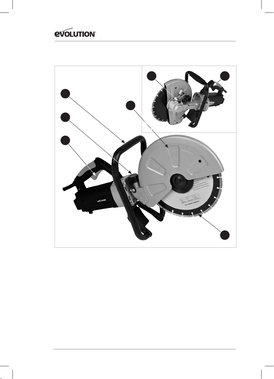
MACHINE OVERVIEW
6
7
5
3
2
1
4
1. Safety Lock Button
2. Trigger Switch
3. Dust Extraction Port
4. Cutting Disc
5. Adjustable Disc Guard
6. Arbor Lock Button
7. Anti-vibration Front handle
12
Page 13
www.evolutionpowertools.com
EN
DE
FR
ES
FIG. 1
FIG. 2
OPERATING INSTRUCTIONS
The tool is recommended to always be supplied via a residual
current device with a rated residual current of 30 mA or less.
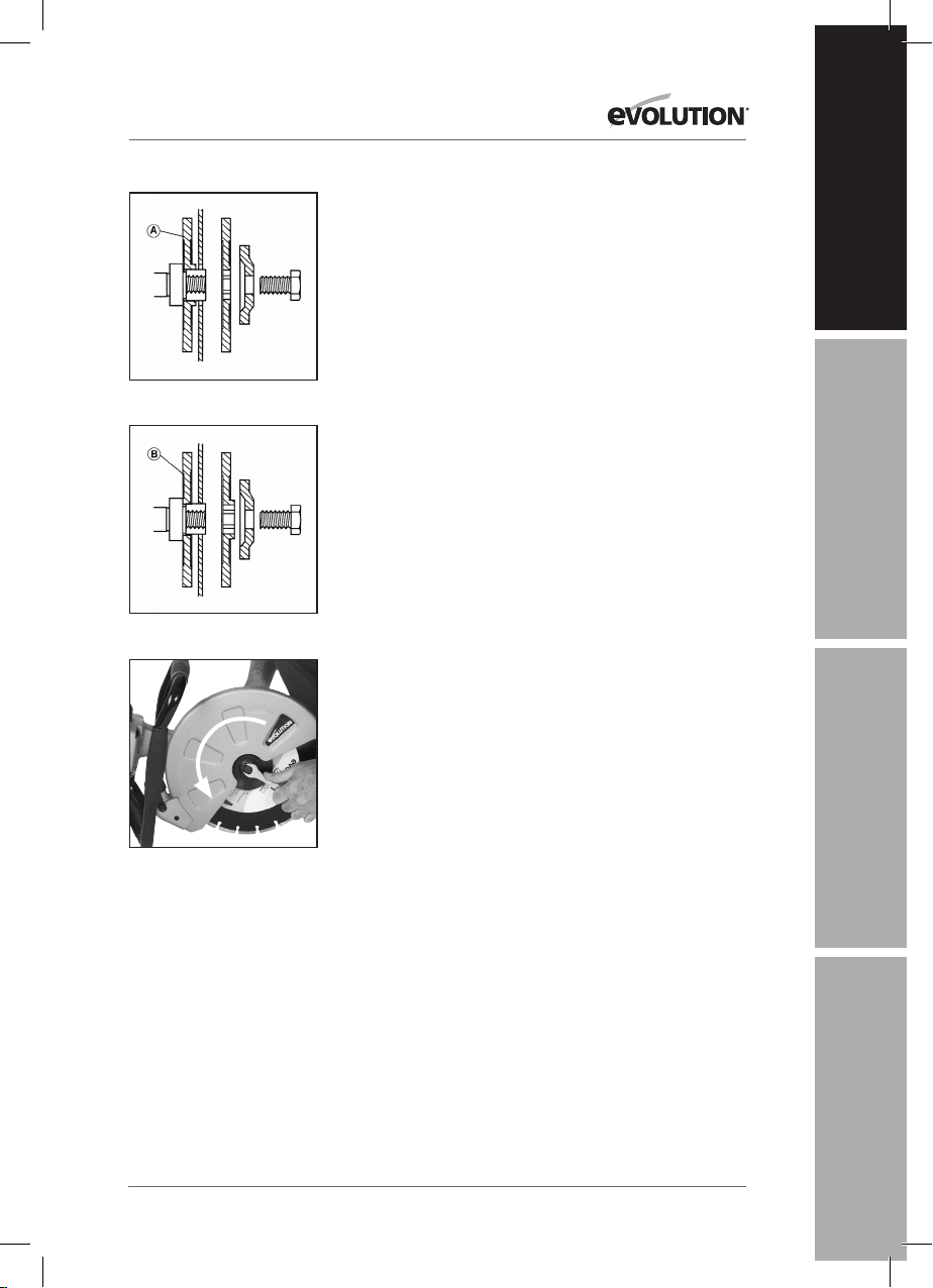
INSTALLING/REMOVING A DISC
WARNING: Always disconnect the machine from the power
supply before attempting to install or remove a Cutting Disc.
• Ensure that the machines arbor and the blade flanges are
clean and free from dust and debris.
• Ensure that the direction of rotation marked on the blade
matches the direction of rotation marked on the machines
guard.
Note: This machine is supplied with two (2) blade f langes. These
can accommodate blades with either a ø20mm (ø3/4”) or ø22.2
(ø7/8”) arbor hole depending upon how they are installed.
• Install blade flange ‘A’ on the inner side when the arbor hole
in the cutting disc is ø22.2mm (ø7/8”). FIG. 1
• Install the blade flange ‘B’ on the inner side when the arbor
hole in the cutting disc is ø20mm (ø3/4”) FIG. 2
• Install the cutting blade and outer blade flange, washer and
arbor bolt.
• Press the arbor lock to lock the machines arbor.
• Tighten the arbor bolt using the supplied spanner. FIG. 3
• Release the arbor lock and check by hand that the Cutting
Disc is secure and correctly positioned on the arbor and that
if rotates freely.
FIG. 3
Note: The arbor bolt has a Left Hand thread. Turn
counterclock wise to tighten the arbor bolt. Turn clockwise to
loosen the arbor bolt.
To remove a Cutting Disc, reverse the above Installation
procedure.
13
Page 14
www.evolutionpowertools.com
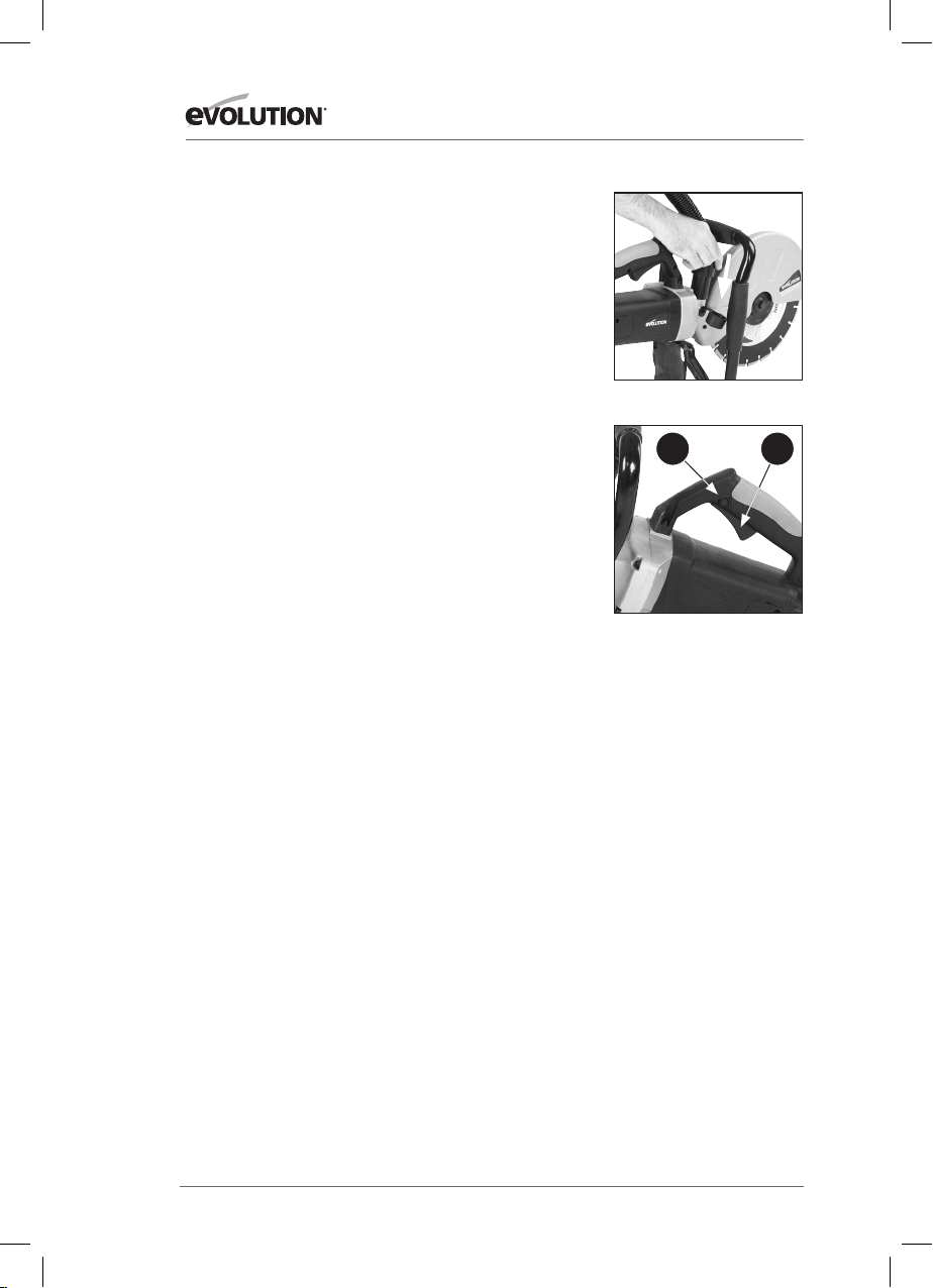
USING A DUST EXTR ACTION MACHINE
A workshop dust extraction machine can be attached to the
Evolution Disc Cutter.
WARNING: Dust can be very dangerous. We strongly
recommend that a suitable dust extraction machine (not
supplied) is used with this machine to keep the workplace as
clean and safe as possible.
The suction hose from the dust extraction machine should be
attached to the dust ex traction port of the Disc Cutter.
• Remove the rubber cap from the dust extraction port and
store it safely for future use.
• Push the connection hose from the dust extraction machine
into the dust extraction port of the Disc Cutter. FIG. 4
• Follow all instructions supplied with the dust extraction
machine when using such with this Disc Cutter.
• Ensure that the hose and power cable of any attached dust
extraction machine do not pose or cause a trip or any other
form of hazard to the operator.
• When the dust extraction machine is no longer required,
remove it from the Disc Cutter and replace the rubber cap to
the dust extraction port.
THE ON/OFF TRIGGER SWITCH
This machine is equipped with a safet y start trigger switch.
FIG. 4
a b
FIG. 5a & 5b
To start the tool:
• Push in the safety lock button (Fi g. 5a) on the side of the
handle with your thumb.
• Depress the main trigger switch (Fig. 5b) to start the motor.
WARNING: Never start the saw with the cutting edge of the
saw blade in contact with the workpiece surface.
14
Page 15

www.evolutionpowertools.com
EN
DE
FR
ES
FIG. 6
CUTTING ADVICE
PRE-CUTTING ADVICE
• Ensure that the power supply matches the requirements
specified on the machines rating plate.
• Ensure that the machines trigger switch is in the ‘OFF’
position. If the machine is connected to a power source with
the trigger switch in the ‘ON’ position, the machine could
start operating immediately with the possibility of a serious
accident occurring.
• If an extension cable is required it must be a suitable type
for use outdoors and so labelled.
• The manufacturers instructions should be followed when
using an extension cable.
• Route any extension cable so that it does not pose a trip (or
any other) hazard to the operator or any bystanders.
WHEEL GUARD ADJUSTMENT
The Wheel Guard is adjustable and should be positioned to
provide the operator with the best combination of personal
protection and visibility of the cutting area.
WARNING: Ensure that the machine is disconnected from the
power supply before adjusting the Wheel Guard.
• Loosen the Wheel Guard locking knob and rotate the Guard
to the required position. FIG. 6
• Securely tighten the Wheel Guard locking knob to lock the
Guard in place.
Note: The tightness of this locking knob and the security of
the Wheel Guard should be checked regularly when operations
commence.
15
Page 16
www.evolutionpowertools.com
CUTTING ADVICE
Mark out all the cutting lines on the workpiece using suitable
media – pencil, crayon, chalk etc. All cutting lines should be
clear and readily visible.
• If possible support the workpiece in such a way that it is
possible to predict what will happen, and that the cut will
remain stable and open while cutting. (FIG. 7)
• Always align the diamond wheel with a pre-marked cutting
line before beginning operations, but ensure that the
diamond wheel is not touching the workpiece.
• Switch the machine ‘ON’ and allow the blade to reach its full
operational speed.
• Gently feed the blade into the workpiece. Cutting
performance is best when you cut straight ahead along the
pre-marked cutting line. Do not cut a depth of greater than
50mm (2”). FIG. 8 If a cut of greater than 50 mm (2”) is
required make several passes.
• Cut smoothly, allowing the machine to work without forcing
the blade.
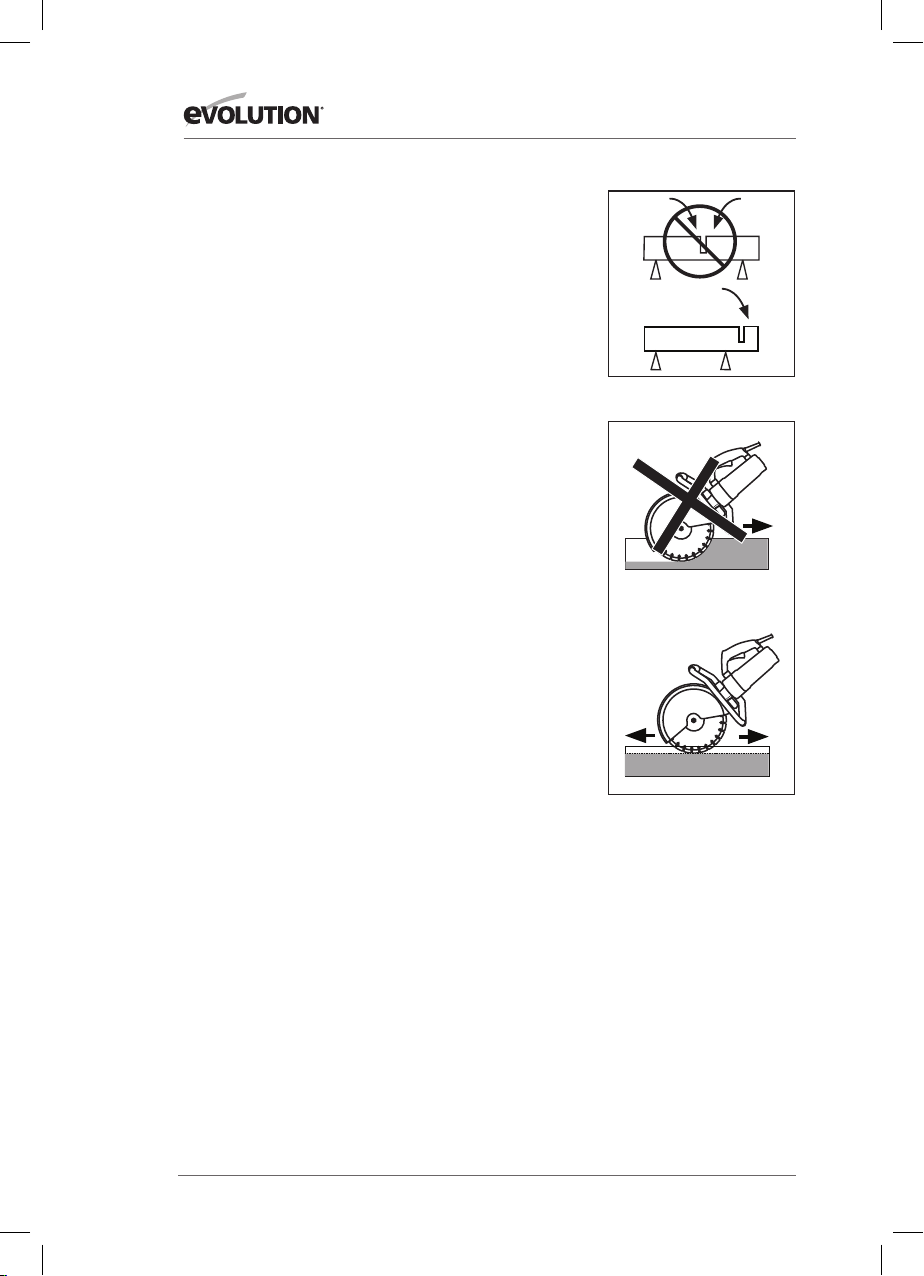
WARNING: Do not attempt to cut curved or zig zag lines.
Never use the side of the blade as a cutting surface. Never use
to perform inclination cutting.
• Do not apply water or coolant to the diamond blade.
• Move the blade slowly backwards and forwards and try to
achieve a small contact area between the blade and the
workpiece being cut. This reduces the temperature of the
blade and ensures efficient cutting.
• If the blade seizes or there is any abnormal noise,
immediately turn the power ‘OFF’ and investigate the
cause. Determine the cause of any noise or stoppage. Only
recommence cutting if it is safe to do so.
• Feed the machine down in line with the blade. Sideways
pressure on the blade disc can damage it and can be very
dangerous.
FIG. 7
FIG. 8
16
Page 17

www.evolutionpowertools.com
EN
DE
FR
ES
(6 .1) MAINTENANCE
Note: Any maintenance must be carried out with the machine
switched off and disconnected from the mains/battery power
supply.
Check that all safety features and guards are operating
correctly on a regular basis. Only use this machine if all guards/
safety features are fully operational.
All motor bearings in this machine are lubricated for life. No
further lubrication is required.
Use a clean, slightly damp cloth to clean the plastic parts of the
machine. Do not use solvents or similar products which could
damage the plastic parts.
WARNING: Do not attempt to clean by inserting pointed
objects through openings in the machines casings etc. The
machines air vents should be cleaned using compressed dry air.
Excessive sparking may indicate the presence of dirt in the
motor or worn out carbon brushes.
(6.2)
If this is suspected have the machine serviced and the brushes
replaced by a qualified technician.
(6.4)
ENVIRONMENTAL PROTECTION
Waste electrical products should not be disposed of with
household waste. Please recycle where facilities exist. Check
with your Local Authority or retailer for recycling advice.
17
Page 18

www.evolutionpowertools.com
DECLARATION OF CONFORMITY
The manufacturer of the product covered by this Declaration is:
Evolution Power Tools, Venture One, Longacre Close, Holbrook Industrial Estate, Shef field, S20 3FR
The manufacturer hereby declares that the machine as detailed in this declaration fulfils all the
relevant provisions of the Machinery Directive and other appropriate directives as detailed below.
The manufacture further declares that the machine as detailed in this declaration, where
applicable, fulfils the relevant provisions of the Essential Health and Safety requirements.
The Directives covered by this Declaration are as detailed below:
200 6/42/EC. Machinery Directive.
2014/30/EU. Electromagnetic Compatibility Directive.
93/68/EC. The CE Mark ing Directive .
20 11/6 5/E U. The Rest riction of the Us e of certain Haz ardous Substan ces in Electric al Equipment (Ro HS) Directive.
2002/96/EC. as amend ed by 2003/108/EC The Waste E lectrical an d Electronic Equ ipment (WEEE) Di rective.
And is in conformity with the applicable requirements of the following documents
EN 60745-1/A11:2010 • EN IS O 12100: 2010 • EN 55014-1: 2017 • EN 55014-2: 2015 •
EN61000-3 -2: 2014 • EN61000-3 -3: 2013
Product Details
Description: Evolution 305mm (12”) Multipurpose Electric Disc Cutter
Brand Name: Evolution Build
Voltage: 110V / 230-240V ~ 50Hz / 60Hz
Input: 1800W (120v) 2000W (110v) 2400W (230v)
The technical documentation required to demonstrate that the product meets the requirements
of directive has been compiled and is available for inspection by the relevant enforcement
authorities, and verifies that our technical file contains the documents listed above and that they
are the correct standards for the product as detailed above.
Name and address of technical documentation holder.
Signed: Print: Matthew Gavins - Operations Director
Date: 01/03/16
18
Page 19

www.evolutionpowertools.com
EN
DE
FR
ES
Notes
19
Page 20

www.evolutionpowertools.com
INHALTSVERZEICHNIS
English Page 02
Deutsch Seite 20
Français Page 40
Español Página 56
EINLEITUNG Seite 21
Garantie Seite 21
Python Programming Seite 22
Vibration Seite 22
Kennzeichnungen und Symbole Seite 23
Bestimmungsgemäßer Gebrauch des Elektrowerkzeugs Seite 24
Python Programming Gebrauch des Elektrowerkzeugs Seite 24
SICHERHEITSVORKEHRUNGEN Seite 24
Elektrische Sicherheit Seite 24
Verwendung im Freien Seite 24
Allgemeine Sicherheitsanweisungen zu Elektrowerkzeugen Seite 24
Zusätzliche Sicherheitsanweisungen Seite 29
ERSTE SCHRITTE Seite 30
Auspacken Seite 30
Maschinenübersicht Seite 32
Montage und Vorbereitung Seite 33
Betriebsanleitung Seite 33
INSTANDHALTUNG Seite 16
Umweltschutz Seite 37
KONFORMITÄTSERKLÄRUNG Seite 38
20
Page 21

www.evolutionpowertools.com
EN
DE
FR
ES
1.2
DIESES BEDIENUNGSHANDBUCH
WURDE URSPRÜNGLICH IN ENGLISCHER
SPRACHE ERSTELLT.
(1.3)
WICHTIG
Lesen Sie diese Betriebs- und Sicherheitsanweisungen bitte sorgfältig und vollständig
durch.
Sollten Sie sich hinsichtlich der Anwendung
des Elektrowerkzeugs unsicher fühlen,
kontaktieren Sie zu Ihrer eigenen Sicherheit
unsere technische Helpline, deren Nummer
auf der Website von Evolution Power Tools zu
finden ist. Wir bieten weltweit eine Vielzahl von
Helplines an, technische Hilfe ist jedoch auch
über Ihren Einzelhändler verfügbar.
WEB
www.evolutionpowertools.com
(1.4)
Wir gratulieren Ihnen zum Kauf einer
Evolution Power Tools-Maschine.
Bitte f olgen Sie den Anw eisungen des
beiliegenden A4-Merkblattes zur OnlineGarantieregistrierung und registrieren Sie
Ihr Produkt „online“. Sie können ebenfalls
den auf dem A4-Merkblatt enthaltenen QRCode mithilfe eines Smartphones scannen.
Hierdurch aktivieren Sie die Garantiefrist
Ihrer Maschine über die Evolution-Website.
Geben S ie zu diesem Zwec k einfach Ihr e
Kontaktdaten ein und sichern Sie sich
schnellen Kundenservice, wann immer Sie
ihn brauchen. Wir danken Ihnen, dass Sie
sich fü r ein Produkt vo n Evolution Power
Tools entschieden haben.
BEGRE NZTE GARANTIE VON EVOLUTION.
Evolution Power Tools behält sich das
Recht vor, ohne vorherige Mitteilung
konstruktive Verbesserungen und
Änderungen am Produkt vorzunehmen.
Die Garantiebedingungen finden Sie auf
dem Garantieregistrierungs-Merkblatt
und/oder der Verpackung.
(1.5)
Evolution Power Tools repariert oder
ersetzt innerhalb der Garantiefrist und ab
ursprünglichem Kaufdatum alle Waren,
bei denen Mängel im Material oder in der
Ausführungsqualität auftreten.
Diese Garantie ist nichtig, wenn die
zurückgegebene Maschine entgegen den
Empfehlungen des Bedienungshandbuchs
verwendet haben oder sie durch Unfall,
Fahrlässigkeit oder unsachgemäße Wartung
beschädigt worden ist.
Diese Garantie gilt nicht für Maschinen und/
oder Komponenten, die in irgendeiner Form
geändert oder modifiziert oder außerhalb der
empfohlenen Kapazitäten und Spezifikationen
eingesetzt worden sind. Elektrische
Komponenten werden durch die Garantien
der jeweiligen Hersteller abgedeckt. Alle
retournierten defekten Waren sind frachtfrei an
Evolution Power Tools zu senden.
Evolution Power Tools behält sich das
Recht vor, optional eine Reparatur oder
eine Ersatzlieferung mit gleichen oder
gleichwertigen Posten vorzunehmen.
Der Hersteller übernimmt keine Garantie,
weder schriftlich noch mündlich, für
Verbrauchsmaterialien und Zubehör,
einschließlich, jedoch nicht beschränkt auf:
Schneideblätter, Schneider, Bohrer, Meißel,
Rührer usw.
Evolution Power Tools haf tet nicht für direkte
oder indirekte Schäden oder Verluste, die aus
der Verwendung unserer Produkte oder aus
irgendwelchen anderen Gründen entstehen.
Evolution Power Tools haf tet weder für jegliche
Kosten, die für solche Waren entstehen, noch
für Folgeschäden.
Angestellte oder Vertreter von Evolution Power
Tools sind nicht bevollmächtigt, mündliche
Erklärungen zur Eignung abzugeben
oder auf irgendeine der vorstehenden
Geschäftsbedingungen zu verzichten;
derartige Erklärungen haben keinerlei
bindende Wirkung für Evolution Power Tools.
Fragen zu dieser begrenzten Garantie
sind an die Firmenzentrale zu richten
oder über eine n Anruf über die jeweilige
Helpline-Nummer zu klären.
21
Page 22

www.evolutionpowertools.com
TECHNISCHE DATEN
STROM METRISCH IMPERIAL
UK/EU Motor (230-240V ~ 50Hz) 2400 W 10 A
UK Motor (110V ~ 50Hz) 2000 W 18 A
USA Motor (120V ~ 60Hz) 1800 W 15 A
MASCHINE METRISCH IMPERIAL
Maximale Schnitttiefe
*PDie maximale Schnitttiefe kann nur durch progressives/inkrementelles Schneiden erzielt werden.
Geschwindigkeit GB/EU (Leerlauf ) 4500min
Geschwindigkeit USA (Leerlauf ) 5000min
Geschwindigkeit AUS (Leerlauf) 4900min
Schutzklasse Klasse II (GB und EU)/Klasse I (USA)
Schutzgrad IP20
Bruttogewicht 9,5kg 21Pf und
BL ATT METRISCH IMPERIAL
Durchmesser 305mm 12 ”
Bohrun g GB und EU 22.2mm 7/8”
Bohrun g USA 25.4mm 1 ”
Breite 3mm 1/8”
Höchstgeschwindigkeit 5500min
LÄRM UND VIBRATIONSBEZOGENE DATEN
Schalldruck LPA 96.0dB(A) K=3dB(A) 98.3dB(A) K=3dB(A)
Schallleistungspegel LWA 110.0dB(A) K=3dB(A) 112.0dB(A) K=3dB(A)
Vibration des Vordergriffs 3.2 94m/s2 K=1. 5m/s22,273 m/s2 K=1. 5m/s
Vibration des hinteren Griffs 3. 611m /s2 K=1. 5m/s23.788m/s2 K=1. 5m/s
*
100mm 4”
-1
-1
-1
-1
MODELLE MIT
110 V120 V
4500U/min
5000U/min
4900U/min
5500U/min
MODELLE MIT
230 V240 V
2
2
(1.6)
Hinweis: Die Ermittlung des Vibrationspegels
geschah unter Standardbedingungen in
Übereinstimmung mit: BS EN 61029-1:2009
Der angegebene Vibrationswert wurde im
Einklang mit einer Standard-Prüfmethode
gemessen und kann verwendet werden, um
verschiedene Maschinen miteinander zu
vergleichen.
Ebenso kann er für eine erste
Gefahrenbewertung herangezogen werden.
(1.7)
VIBRATION
WARNUNG: Beim Betrieb der Maschine ist der
Bediener u. U. starken Vibrationen (Hand und
Arm) ausgesetzt. Möglicherweise tritt dadurch
beim Bediener die „Weißfingerkrankheit“
(Raynaud-Syndrom) auf. Dies kann die
Temperaturempfindlichkeit der Hand
22
Page 23

www.evolutionpowertools.com
EN
DE
FR
ES
beeinträchtigen und ein allgemeines
Taubheitsgefühl erzeugen. Personen, die
längere Zeit oder regelmäßig mit diesem Gerät
arbeiten, sollten den Zustand ihrer Hände
und Finger aufmerksam beobachten. Falls die
vorgenannten Symptome auftreten, sollte
unverzüglich ärztlicher Rat eingeholt werden.
• Die Messung und Bewertung von
Auswirkungen von Schwingungen auf das
Hand-Arm-System am Arbeitsplatz wird in
folgenden Normen beschrieben:
BS EN ISO 5349-1:2001 und
BS EN ISO 5349-2:2002
• Die Stärke der Vibration wird von einer
Vielzahl von Faktoren beeinflusst,
wie z. B. Beschaffenheit und Ausrichtung
der Arbeitsfläche und Typ und Zustand der
verwendeten Maschine. Diese Faktoren
sollten vor jedem Gebrauch in Betracht
gezogen werden. Wenn möglich, ist für
angemessene Arbeitsbedingungen zu
sorgen. Folgende Einstellungen können
Vibrationen vermindern:
Gebrauch
• Bedienen Sie die Maschine mit
Sorgfalt, lassen Sie sie die Arbeit für Sie
verrichten.
• Wenden Sie nicht unnötig viel Kraft auf
die Bedienelemente der Maschine an.
• Berücksichtigen Sie Sicherheit und
Stabilität sowie die Ausrichtung der
Maschine während Inbetriebnahme.
Arbeitsfläche
• Berücksichtigen Sie das Material Ihrer
Arbeitsfläche; ihren Zustand, Dicke,
Robustheit, Härte und Ausrichtung.
WARNUNG: Die Vibrationen, die bei
der Verwendung des Elektrowerkzeugs
auftreten, können je nach Art und Weise der
Nutzung der Maschine vom angegebenen
Wert abweichen. Das Ausmaß an
Sicherheitsmaßnahmen und Maßnahmen
zum Schutz des Verwenders basiert auf dem
geschätzten Ausmaß an Beanspruchung
(unter Berücksichtigung aller Abschnitte des
Betriebs, wie z. B. Ausschalten der Maschine,
Leerlauf sowie Auslösezeit).
(1.8)
KENNZEICHNUNGEN UND SYMBOLE
WARNUNG: Verwenden Sie die Maschine
nicht, wenn Warnhinweise und/oder
Hinweisschilder fehlen oder beschädigt sind.
Für Ersatz wenden Sie sich an Evolution Power
Too ls.
Hinweis: Manche oder alle der folgenden
Symbole können in der Betriebsanleitung
oder auf dem Produkt abgebildet sein.
SYMBOL BESCHREIBUNG
V Volt
A Ampere
Hz Hertz
-1
Min
~ Wechselstrom
n Nenngeschwindigkeit
RCM REGULATORY COMPLIANCE
AUSTRALISCHE/NEUSEELÄNDISCHE
Drehzahl
Warnung!
Anleitung lesen
Nur Trockenzerspanung
Schutzbrille tragen
Gehörschutz tragen
Staubmaske tragen
Schutzhandschuhe tragen
Sicherheitsstiefel tragen
US-Zertifizierung
CE-Zertifizierung
Entsorgung als Elektro- und
Elektronikschrott
MARK FÜ R ELEKTR ISCHE UND
ELEKTRONISCHE GERÄTE.
NORM
23
Page 24

www.evolutionpowertools.com
(1.10 )
BESTIMMUNGSGEMÄSSER
GEBRAUCH DES
ELEKTROWERKZEUGS
WARNUNG: Dieses Produkt ist ein von
Hand betriebener Trennschleifer und wurde
für den Einsatz mit speziellen EvolutionTrennscheiben entwickelt. Verwenden
Sie ausschließlich für den Gebrauch mit
dieser Maschine entwickeltes und/oder
ausdrücklich von Evolution Power Tools Ltd
empfohlenes Zubehör.
Mit geeigneter Trennscheibe kann diese
Maschine zum Schneiden der folgenden
Materialien verwendet werden:
Ziegel
Pflastersteine
Bordsteinkanten
Beton
1.11
UNZULÄSSIGER GEBRAUCH DES
ELEKTROWERKZEUGS
WARNUNG: Dieses Produkt ist ein von Hand
betriebener Trennschleifer und ist nicht
anderweitig zu verwenden. Es dürfen keinerlei
Modifikationen vorgenommen werden.
Weiterhin darf die Maschine nicht mit anderer
Ausrüstung oder anderem Zubehör als dem in
dieser Betriebsanleitung erwähnten in Betrieb
genommen werden. (1.11)
WARNUNG: Diese Maschine darf nicht zum
Schneiden von potenziell asbesthaltigem
Material verwendet werden. Sollte der
Verdacht bestehen, dass sich im Material
Asbest befindet, holen Sie sich Rat von der
zuständigen Behörde ein.
(1.13)
WARNUNG: Diese Maschine ist nicht
bestimmt zur Nutzung durch Personen
(einschließlich Kindern) mit eingeschränkten
körperlichen, sensorischen bzw. geistigen
Fähigkeiten, mangelnder Erfahrung bzw.
fehlendem Wissen, sofern diese nicht durch
eine für ihre Sicherheit verantwor tliche Person
eine Beaufsichtigung bzw. Anweisung für
die sichere Nutzung der Maschine er fahren
haben.
Kinder müssen beaufsichtigt werden, um
sicherzustellen, dass sie keinen Zugang zu der
Maschine haben und nicht mit ihr spielen.
(1.14 )
ELEKTRISCHE SICHERHEIT
Diese Maschine ist ausgestattet mit den auf
dem Zielmarkt jeweils verwendeten Stecker
und Anschlusskabel. Bei Beschädigung des
Anschlusskabels ist dieses durch ein vom
Hersteller oder dessen Händler zur Verfügung
gestelltes Kabel zu ersetzen.
(1.15 )
VERWENDUNG IM FREIEN
WARNUNG: Zu Ihrer eigenen Sicherheit
sollte diese Maschine bei Verwendung im
Freien nicht Regen ausgesetzt werden und
nicht in einer feuchten Umgebung eingesetzt
werden. Platzieren Sie die Maschine nicht auf
feuchtem Untergrund.
Wenn verfügbar, arbeiten Sie auf einer
sauberen, trockenen Fläche. Verwenden Sie
für zusätzlichen Schutz eine FehlerstromSchutzeinrichtung (R.C.D.), die bei Leckstrom
von über 30 mA über einen Zeitraum von
30 ms die Stromzufuhr unterbricht.
Überprüfen Sie vor Verwendung der
Maschine jedes Mal die FehlerstromSchutzeinrichtung (R.C.D.).
Ist ein Verlängerungskabel notwendig, muss
dieses für den Gebrauch im Freien geeignet
und entsprechend gekennzeichnet sein.
Folgen Sie den Anweisungen des Herstellers
bei Verwendung mit Verlängerungskabel.
(2 .1)
ALLGEMEINE
SICHERHEITSANWEISUNGEN ZU
ELEKTROWERKZEUGEN
WARNUNG: Lesen Sie sorgfältig alle
Warnhinweise und Anweisungen.
Nichtbeachtung der Warnhinweise und
Anweisungen kann zu Stromschlag, Brand
und/oder schweren Verletzungen führen.
Bewahren Sie alle Warnhinweise und
Anweisungen zu Referenzzwecken auf.
24
Page 25

www.evolutionpowertools.com
EN
DE
FR
ES
Der Begriff „Elektrowerkzeug“ in
den Warnhinweisen bezieht sich auf
Ihr netzbetriebenes (verkabeltes)
Elektrowerkzeug oder Ihr Batteriebetriebenes (kabelloses) Elektrowerkzeug.
(2.2)
1) Allgemeine Sicherheitswarnungen
zum Elektrowerkzeug [Sicherheit am
Arbeitsplatz]
a) Halten Sie den Arbeitsbereich sauber
und sorg en Sie für eine gute Beleuchtu ng.
Zugestellte oder dunkle Bereiche
begünstigen Unfälle.
b) Verwenden Sie das E lektrowerk zeug
nicht in explosionsgefährdeten
Bereichen wie z. B. bei Vorhandensein
brennbarer Flüssigkeit, Gase oder Staub.
Elektrowerkzeuge erzeugen Funken, die
Staub oder Gase entzünden können.
c) Halten Sie Kinder und Unbeteiligte
während Inbetriebnahme vom
Elektrowerkzeug fern. Ablenkungen
können dazu führen, dass Sie die Kontrolle
über das Werkzeug verlieren.
(2.3)
2) Allgemeine Sicherheitswarnungen zum
Elektrowerkzeug [Elektrische Sicherheit]
a) Der Stecker des Elektrowerk zeugs
muss zur Steckdose passen. Den Stecker
niemals modifizieren. Verwenden
Sie keine Adapter mit geerdeten
Elektrowerkzeugen. Nicht modifizierte
Stecker und dazu passende Steckdosen
verringern das Risiko eines Stromschlags.
b) Vermeiden Sie den Kontakt mit
geerdeten Oberflächen wie z. B. Rohren,
Heizungen, Herden oder Kühlschränken.
Das Risiko auf Stromschlag steigt, wenn Ihr
Körper geerdet ist.
c)Setzen Sie Elektrowerkzeuge nie Regen
oder nassen Bedingungen aus. Wasser, das
in ein Elektrowerkzeug eindringt, erhöht das
Risiko eines Stromschlags.
d) Verwenden Sie das Kabel nicht
unzweckmäßig. Verwenden Sie das
Kabel nicht, um das Elektrowerk zeug zu
transportieren oder zu ziehen oder den Stecker
herauszuziehen. Halten Sie das Netzkabel
fern von Hitze, Öl, scharfen Kanten oder sich
bewegenden Geräteteilen. Beschädigte oder
verwickelte Kabel erhöhen das Risiko eines
Stromschlags.
e) Verwenden Sie ein geeignetes
Verlängerungskabel, wenn Sie das
Elektrowerk-zeugs im Freien betreiben.
Die Verwendung eines für den Gebrauch im
Freien vorgesehenen Verlängerungskabels
vermindert das Risiko eines Stromschlags.
f) Ist die Verwendung des
Elektrowerkzeugs in feuchter Umgebung
unumgänglich, verwenden Sie eine
Fehlerstrom-Schutzeinrichtung (R.C.D.).
Die Verwendung einer FehlerstromSchutzeinrichtung verringert das Risiko eines
Stromschlags.
(2.4)
3) Allgemeine Sicherheitswarnungen
zum Elektrowerkzeug [Persönliche
Sicherheit].
a) Seien Sie beim Be trieb des
Geräts immer aufmerksam und
verantwortungsbewusst. Verwenden
Sie das Elektrowerkzeug nicht bei
Müdigkeit oder unter Einfluss von Drogen,
Alkohol oder Medikamenten. Kurze
Unachtsamkeit während der Verwendung
dieses Elektrowerk zeugs kann zu schweren
körperlichen Verletzungen führen.
b) Verwenden Sie persönliche
Schutzausrüstung. Tragen Sie stets
eine Schutzbrille. Das Tragen von
Schutzausrüstung wie Staubmaske,
rutschfesten Sicherheitsschuhen, Schutzhelm
oder Gehörschutz verringert das Risiko von
Verletzungen.
c) Vermeiden Sie unbeabsichtigte
Inbetriebnahme. Vergewissern Sie sich,
dass das Werkzeug ausgeschaltet ist, bevor Sie
es an die Stromquelle und/oder an die Batterie
anschließen, anheben oder transportieren.
Das Tragen von Elektrowerkzeugen mit dem
Finger am Schalter oder die Aktivierung der
Stromversorgung einer Maschine, deren
Schalter in der Stellung „ON“ (An) steht, kann
zu Unfällen führen.
d) Entfernen Sie alle Einstell- und
sonstigen Schlüssel, bevor Sie das
25
Page 26

www.evolutionpowertools.com
Elektrowerkzeug einschalten.
Schraubenschlüssel oder andere
Schlüssel, die in sich bewegenden Teilen
des Elektrowerkzeugs stecken, können
körperliche Verletzungen verursachen.
e) Nicht zu weit hinauslehnen. Achten
Sie stets auf guten Stand bzw. gute Balance.
Dies sorgt für eine bessere Kontrolle des
Elektrowerkzeugs in unerwarteten Situationen.
f) Tragen Sie angemessene Kleidung.
Tragen Sie keine weite Kleidung oder
Schmuck. Halten Sie Haare, Kleidung und
Handschuhe fern von sich bewegenden
Teilen. Weite Kleidung, Schmuck oder langes
Haar kann sich in sich bewegenden Teilen
verfangen.
g) Falls Vorrichtungen zum Absaugen
und Sammeln von Staub vorhanden sind,
schließen Sie diese an und verwenden
Sie sie ordnungsgemäß. Die Verwendung
eines Staubabscheiders vermindert durch
Staub verursachte Gefahren.
(2.5)
4) Allgemeine Sicherheitswarnungen
zum Ele ktrowerk zeug [Gebrauc h und
Instandhaltung].
a) Wenden Si e keine Gewalt a n.
Verwenden Si e ein für Ihre Zwecke geeigne tes
Elektrowerkzeug. Das passende Elektrowerkzeug
erledigt die Arbeit besser und sicherer in
angemessenem Tempo.
b) Verwenden Sie das Elektrowerkzeug
nicht, wenn der Schalter nicht ein- und
ausschaltet. Jedes Elektrowerkzeug, dessen
Ein-/Ausschalter nic ht funktionier t, stellt eine
Gefahr dar und muss repariert werden.
c) Trennen Sie das Elektrowerkzeug von der
Netzquelle und/oder der Batterie, bevor
Sie Änderungen vornehmen, Zubehör
auswechseln oder das Elektrowerkzeug
lagern. Derartige vorbeugende Maßnahmen
verringern das Risiko, dass das Elektrowerkzeug
unbeabsichtigt starte.t
d) Bewahren Sie unbenutzte Geräte
außerhalb der Reichweite von Kindern auf
und lassen Sie Personen, die mit dem Gerät
nicht vertraut sind oder diese Anweisungen
nicht gelesen haben, das Gerät nicht
benutzen. Das Gerät kann gefährlich sein, wenn
es von unerfahrenen Personen benutzt wird.
e) Halten Sie Elektrowerkzeuge instand.
Stellen Sie sicher, dass sich alle beweglichen Teile
in der richtigen Position befinden, keine Teile
gebrochen sind oder sonstige Fehler vorliegen,
um den reibungslosen Betrieb des Geräts
sicherzustellen. Sollten Schäden vorliegen, lassen
Sie das Elektrowerkzeug vor Gebrauch reparieren.
Viele Unf älle werden von schlecht in stand
gehaltenen Elektrowerkzeugen verursacht.
f) Halten Sie Schneidewerkzeug scharf
und saub er. Angemessen gepflegtes
Schneidewerkzeug mit scharfen Klingen läuft
geschmeidiger und ist leichter zu kontrollieren.
g) Verwenden Sie das Elektrowerkzeug,
Zubehör und Werkzeugteile usw.
in Übereinstimmung mit diesen
Anweisungen unter Berücksichtigung der
Arbeitsumstände und der auszuführenden
Arbeit. Unzweckmäßige Verwendung des
Elektrowerkzeu gs kann zu Gefahr führe n.
(2.6)
5) Allgemeine Sicherheitswarnungen zum
Elektrowerkzeug [Wartung]
a) Lassen Sie Ihr Elektrowerkzeug von
qualifiziertem Fachpersonal und nur
mit identischen Ersatzteilen reparieren.
Dadurch wird die fortwährende Sicherheit des
Elektrowerkzeugs gewährleistet.
(2.7)
GESUNDHEITSHINWEISE
WARNUNG: WBei Arbeiten mit dieser Maschine
können Staubpartikel entstehen. Je nachdem,
mit welchem Material Sie arbeiten, kann dieser
Staub beson ders schädlich sein. Su chen Sie
professionelle Hilfe auf, wenn Sie vermuten, dass
die Farbe auf dem Material, das Sie schneiden
wollen, Blei enthält.
Auf Blei basierte Farben sind von professionellen
Fachkräften zu entfernen. Von Selbstversuchen
ist abzuraten . Hat sich der Staub auf Ober flächen
abgesetzt, k ann Hand- Mund-Kontakt zur
Aufnahme von Blei führen. Schon geringe
Mengen an Blei können unwiderrufliche
Schäden an Hirn und Nervensystem verursachen.
Junge und ungeborene Kinder sind besonders
gefährdet. Ziehen Sie die Risiken verbunden
mit dem Material, mit dem Sie arbeiten, in
26
Page 27

www.evolutionpowertools.com
EN
DE
FR
ES
Erwägung und verringern Sie das Risiko, sich dem
auszusetzen. Da manche Materialien potenziell
gesundheitsschädliche n Staub produz ieren,
empfehlen wir die Verwendung von geprüften
Schutzmasken mit austaus chbaren Filtern
während der Verwendung der Maschine.
Sie sollten stets:
• in gut belüfteten Bereichen arbeiten.
• ge prüfte Schutz ausrüstung tragen, z . B.
Staubmasken f ür die Filterung mikroskop isch
kleiner Partikel.
SICHERHEITSANWEISUNGEN FÜR
TRENNSCHLEIFVERFAHREN
Sicherheitshinweise zu Schneidegeräten
a) Die mit dem Werkzeug bereitgestellte
Schutzvorrichtung muss für maximale
Sicherheit fest am Elektrowerkzeug
angebracht und so positioniert sein, dass
der Anteil des gegenüber des Verwenders
freigelegten Schneideblatts so gering
wie möglich ausfällt. Positionieren Sie
sich selbst und Umstehende nicht in der
Ebene des rotierenden Schneideblatts. Die
Schutzvorrichtung schützt den Verwender vor
Schneideblattfragmenten und versehentlichem
Kontakt mit der Trennscheibe.
b) Verwende n Sie für Ihr Ele ktrowerk zeug
ausschließlich verstärkte Verbund- oder
Diamanttrennscheiben. Nur weil si ch
ein Zubehörteil am Werkzeug befestigen
lässt, be deutet das nicht, dass es sich
auch für einen sicheren Betrieb eignet.
c) Die auf dem Zubehörteil angegebene
Geschwindigkeit muss mindestens der
Höchstgeschwindigkeit des Elektrowerkzeugs
entsprechen. Zubehörteile, die mit einer
Geschwindigkeit betrieben werden, die ihre
Nenngeschwindigkeit übertrifft, können zerbrechen
und auseinanderfliegen.
d) Trennscheibe n dürfen nur für die
empfohlenen Zwecke eingesetzt werden.
Beispiel: Mit der Seite einer Trennscheibe
nicht schleifen. Trennscheiben eignen sich nur
zum Umfangschleifen. Werden Seitenkräf te auf sie
ausgeübt, können sie zerbrechen.
e) Verwenden Sie nur unbeschädigte
Scheibenflansche mit dem passenden
Durchmesser für die ausgewählte Scheibe.
Die passenden Scheibenflansche stützen die
Trennscheibe und senken die Wahrscheinlichkeit,
dass sie zerbricht.
f) Verwenden Sie keine abgenutzten,
verstärkten Scheiben größerer
Elektrowerkzeuge. Für größere
Elektrowerkzeuge gefertigte Scheiben eignen
sich nicht für di e hohen Geschwindigke iten
kleinerer Geräte und können zerbrechen.
g) Der Außendurchmesser und die Stärke Ihres
Zubehörteils müssen innerhalb der für Ihr
Elektrowerkzeug angegebenen Grenzwerte
liegen. Zubehörteile der falschen Größe lassen
sich nicht ausreichend steuern oder schüt zen.
h) Das Dornmaß der Scheiben und
Flansche muss mit dem der Spindel des
Elektrowerkzeugs übereinstimmen.
Scheiben und Flansche, deren Dornbohrungen nicht
zu den Maßen der Hardware des Elektrowerk zeugs
passen, sin d beim Betrieb nicht ausg ewuchtet,
erzeugen übermäßige Vibrationen und können zum
Kontrollverlust führen.
i) Verwenden Sie keine beschädigten
Scheiben. Prüfen Sie die Scheiben vor jedem
Einsatz auf Absplitterungen und Risse.
Sollte das Elektrowerkzeug oder die Scheibe
herunterfallen, müssen Sie sie auf Schäden
untersuchen oder eine unbeschädigte
Scheibe einsetzen. Positionieren Sie sich und
Umstehende nach der Prüfung und Installation
nicht in der Ebene der sich drehenden Scheibe
und bet reiben Sie da s Elektro werkzeug
eine Minute mit der maximalen
Leerlaufgeschwindigkeit. Beschädigte Scheiben
zerbrechen meist während dieses Prüfzeitraums.
j) Tragen Sie persönliche Schutzausrüstung.
Verwenden Sie, abhängig von der
auszuführenden Arbeit, einen Gesichtsschutz
oder eine Schutzbrille. Tragen Sie bei Bedarf
eine Staubmaske, einen Gehörschutz,
Handschuhe und eine Arbeitsschürze, die
kleine Fragmente der Trennscheibe oder
des Werk stücks auf hält. Der verwendete
Augenschutz muss umherfliegende Teile
abhalten können, die durch unterschiedlichste
Prozesse ents tehen. Die Staubmaske bz w. das
Atemgerät muss d azu in der Lage sein, dur ch die
vorgenommenen Arbeiten erzeugte Partikel aus der
27
Page 28

www.evolutionpowertools.com
Luft zu f iltern. Eine langfris tige Lärmbelast ung kann
zum Gehörverlust führen..
k) Umstehende müssen Sicherheitsabstand
zum Arbeitsbereich einhalten. Personen,
die den Arbeitsbereich betreten, müssen
persönliche Schutzausrüstung tragen.
Fragmente des Werks tücks oder einer beschädigten
Scheibe kön nen davonfliegen un d auch außerhalb
der unmittelbaren Arbeitsumgebung zu
Verletzungen führen.
l) Führen Si e das Elekt rowerkzeu g nur mit Hilfe
von isoli erten Gri ffen, wenn Si e eine Arbeit
durchführen, bei der die Zubehörteile nicht
sichtbare Kabel oder das eigene Netzkabel
berühren könnten.
Beim Kontakt des Schneidzubehörs mit einem
stromführenden Kabel können nicht isolierte
Bauteile des Elektrowerkzeugs ebenfalls Strom leiten
und dem Verwender einen elektrischen Schlag
versetzen.
m) Halten Sie das Kabel vom sich drehenden
Zubehö r fern. Falls Sie die Kontroll e verlieren,
könnte das Kab el durchschnitten werde n oder sich
verhaken und Ih re Hand oder Ihr Arm könnte in di e
Trennscheibe gezogen werden.
n) Legen Si e das Elekt rowerkzeu g erst ab, wenn
das Zubehör stillsteht. Die sich drehende Scheibe
könnte sich in der O berfläche ver haken und das
Elektrowerkzeug aus Ihren Händen ziehen.
o) Schalten Sie das Elektrowerkzeug nicht
ein, wenn Sie es transportieren. Beim
versehentlichen Kontakt mit der sich drehenden
Scheibe könnte diese sich in der Kleidung verhaken
und das Gerä t in Ihren Körper ziehen .
p) Reinigen Sie die Lüftunge n des
Elektrowerkzeugs regelmäßig. Der Lüfter des
Elektromotors zieht Staub ins Gehäuseinnere und
große Ansammlungen von Metallpulver führen zu
einer erhöhten Stromschlaggefahr.
q) Betre iben Sie das E lektrower kzeug nic ht
in der Umgebung brennbarer Stoffe. Diese
könnten sich durch Funken entzünden.
r) Verwende n Sie kein Zube hör, für das
Kühlflüssigkeiten benötigt werden. De r Einsatz
von Wasser oder anderen Kühlflüssigkeiten kann zu
Stromschlägen oder gar zum Tod durch Stromschlag
führen.
WEITERE SICHERHEITSANWEISUNGEN FÜR
TRENNSCHLEIFVERFAHREN
T
Hinweise zu Ausschlagbewegungen und
Ähnlichem
Beim Ausschla gen handelt es sich um eine p lötzliche
Reaktion, hervorgerufen durch eine eingeklemmte
oder sich verhakende rotierende Scheibe. Wird eine
sich drehende Scheibe eingeklemmt oder verhakt
sie sich, wird ih re Bewegung abrupt geb remst,
sodass das unkontrollierte Elektrowerkzeug am
entsprechenden Klemmpunkt in die Richtung
gedrückt wird, die der Drehrichtung der Scheibe
entgegengesetzt ist. Verklemmt oder verhakt sich
eine Trennscheibe beispielsweise im Werkstück,
kann sich die K ante, die sich in diesen Kle mmpunkt
hineinbew egt, in die Oberf läche des Werkstof fs
graben und s o dazu führen, dass die Sch eibe
ausschlägt oder sich anhebt.
Die Scheibe kann entweder auf den Verwender zu
oder von ihm we g springen, abhängig d avon, i n
welche Richt ung sich die Scheibe am Kl emmpunkt
bewegt. Unter diesen Umständen können
Trennscheiben auch zerbrechen. Ausschlagen
bzw. Ausreißen eines Elektrowerk zeugs ist das
Ergebnis unsachgemäßer Verwendung und/oder
ungeeigneter Arbeitsverfahren oder -bedingungen
und kann mit Hilfe der nachfolgenden
Vorkehrungen vermieden werden.
a) Halten Sie das Elek trowerkze ug
immer gut fest und positionieren
Sie Arm un d Körper so, dass Si e
Ausschlagbewegungen entgegenwirken
können. Verwenden Sie für maximale
Kontrolle über Ausschlagbewegungen
oder Drehmomentreaktionen während des
Startens immer den Zusatzgriff, falls ein
solcher vorhanden ist. Der Verwender kann durch
entsprechende Vorsichtsmaßnahme n Ausschlag und drehmomentbedingte Bewegungen unter
Kontrolle bringen.
b) Legen Sie Ihre Hand niemals neben das
rotierende Zubehör. Das Zubehör kann beim
Ausschlagen über Ihre Hand fahren.
c) Positionieren Sie Ihren Körper nicht auf der
Linie der sich drehenden Scheibe. Bei einer
Ausschlagbewegung wird das Werkzeug in die
Richtung beschleunigt, die der Bewegungsrichtung
der Scheibe am Klemmpunkt entgegengesetzt ist.
28
Page 29

www.evolutionpowertools.com
EN
DE
FR
ES
d) Gehe n Sie bei der Bea rbeitung von
Ecken, scharfen Kanten usw. vorsichtig vor.
Vermeiden Sie ein Federn oder Verkanten der
Scheibe. Ecken, scharfe Kanten oder federnde
Bewegungen führen häuABB dazu, dass sich
das rotierende Zubehörteil verkantet, was zum
Kontrollverlust oder zu Ausschlagbewegungen
führen kann.
e) Verwenden Sie keinesfalls eine Sägekette,
Schnitzklinge, segmentierte Diamantscheibe
mit ein em peripher en Spalt von me hr als
10 mm oder ei n gezahntes S ägeblatt . Solche
Blätter führen häufig zu Ausschlagbewegungen und
Kontrollverlust.
f) Blockieren Sie die Scheibe nicht und üben Sie
nicht zu viel Kraft darauf aus. Versuchen Sie
nicht, eine zu große Schnitttiefe zu erzwingen.
Bei einer Überbelastung kann die Scheibe im
Schnittbereich verbiegen oder sich verformen, was
unter Umständen zu Ausschlagbewegungen oder
zum Zerbrechen der Scheibe führen kann.
g) Sollte sich die Scheibe festfressen oder wird
der Schneidvorgang aus einem beliebigen
Grund unterbrochen, schalten Sie das
Elek trowerkze ug ab und beweg en Sie es nicht ,
bis es zum Stillstand kommt. Versuchen Sie
keinesfalls, die Scheibe aus dem Schnitt zu
ziehen, solange sie sich noch dreht, da dies zu
Ausschlagbewegungen führen kann. Stellen Sie
den Grund f ür das Festfressen fe st und sorgen Sie
für Abhilfe.
h) Beginnen Sie den Schneidevorgang
nicht i m Werkstück . Starten Sie e rst das
Werkzeug und warten Sie, bis die Scheibe ihre
Betriebsgeschwindigkeit erreicht hat, bevor
Sie sie wieder in den Schnitt einführen. Wird
das Elekt rowerkzeug im Werk stück gestartet , kann
dies zum Fest fressen, einer Auf wärtsbewegun g oder
zum Ausschlagen führen.
i) Stützen Sie Platten oder andere
große Wer kstücke ab, u m das Risiko
des Einklemmens und Ausschlagens zu
minimieren. Große Werkstücke geben häufig unter
ihrem eigen en Gewicht nach. Stütze n Sie solche
Werkstücke auf beiden Seiten der Scheibe sowohl in
der Nähe der S chnittlinie als auch an de n Enden ab.
j) Seien Sie besonders vorsichtig, wenn Sie
einen „Aufsetzschnitt“ an vorhandenen
Wänden oder sonstigen Blindflächen
vornehmen. Die hervorstehende Scheibe
kann Gas- oder Wasserrohre, Stromleitungen
oder Objekte beschädigen, die zu einer
Ausschlagbewegung führen.
(2.8)
WARNUNG: Bei der Arbeit mit Elektro-
werkzeugen können Objekte in Richtung Ihrer
Augen geschleudert werden. Dies kann zu
schweren Verletzungen der Augen führen. Tragen
Sie vor Inbetriebnahme des Elektrowerkzeugs
immer eine Sicherheitsbrille oder eine Schutzbrille
mit seitlichem Schutz oder, wenn notwendig,
einen Gesichtsschutz .
ZUSÄTZLICHE SICHERHEITSANWEISUNGEN
WARNUNG: Trennen Sie den Trennschleifer vor
dem Austausch einer Trennscheibe, vor Wartungsoder Reinigungsarbeiten oder Anpassung des
Trennschleifers stets von der Stromquelle.
• H alten Sie Ihre Hände vom Schn eidbereich
und der Trennscheibe fern. Halten Sie mit
einer Hand den Griff oder das Motorgehäuse
fest. Sol lten Sie die Maschine mit be iden
Händen festhalten, dürfen sie nicht mit der
Diamantscheibe in Kontakt kommen.
• Betätigen Sie den Spindelsperrknopf
keinesfa lls, wenn die Maschine läuf t.
Dies könnte zu sc hweren Schäden an der
Maschine un d potenziell zur Entste hung von
Gefahrensituationen für den Verwender führen.
• Verwenden Sie nur Diamantscheiben oder
andere zugelassene Trennscheiben, die
den Angaben des Herstellers entsprechen.
Betreiben Sie den Trennschleifer nicht, wenn
Sie Wasser verwenden. Bei den Trennscheiben
handelt es sich um Trockentrennscheiben.
• Pr üfen Sie die Diamantsch eibe immer, bevor Sie
die Maschine einschalten. Sind Risse erkennbar
oder ist die Scheibe gebrochen oder verbogen,
darf sie nicht verwendet werden. Schalten Sie
die Maschine v orsichtig ein und achten Sie au f
ungewöhnliche Geräusche, Vibrationen und
andere Vorkommnisse.
• G ehen Sie beim Schneid en von Metall
vorsichtig vo r. Wird di e Diamantscheibe für
das Schneiden von Metallgegenständen
(wie in Beton eingegossenen Stützs treben)
verwendet, führt dies zu einer Verkürzung der
Produktlebensdauer und möglicherweise zur
Beschädigung der Scheibe.
• Warten Sie vor Beginn eines Schneidvorgangs,
29
Page 30

www.evolutionpowertools.com
bis die Scheibe ihre Betriebsgeschwindigkeit
erreicht hat. Beginnen Sie mit Ihren Arbeiten
erst, wenn die Höchstgeschwindigkeit erreicht
ist.
• Üb en Sie nicht zu viel Druck au s. Bei einem zu
hohen Druck wird der Elektromotor überlastet
und die Arbeitseffizienz verringert und die
Produktlebensdauer verkürzt sich. Schneiden
Sie Beton, Flie sen oder Stein stets mit ei ner
maximale n Schnitttiefe vo n 50 mm. Ist eine
Schnitt tiefe von mehr als 50 mm er forderlich,
schneiden Sie das Werkstück in zwei oder
drei Schritten. Wird das Werkstück mit einer
Schnitt tiefe von mehr als 50 mm zer trennt,
verkürzt sich die Produktlebensdauer der
Diamantscheibe und der Elektromotor könnte
sich festfressen.
• Installieren Sie den Entstaubungsanschluss,
wenn Sie keinen Staubsammelschlauch
verwenden. Decken Sie den Entstaubungsanschluss bei Schneidarbeiten, während
denen Funken entstehen können, mit der
zugehörigen Gummikappe ab und tragen Sie
eine Schutzbrille.
• Verwenden Sie keinesfalls beschädigte
Schrauben oder Scheibenflansche oder
solche mit einem falschen Dornmaß. Die
Scheibenflansche und Dornschrauben
sind im Hinbli ck auf optimale Leistung u nd
Betriebssicherheit speziell auf Ihr Gerät
abgestimmt.
• D ieses Gerät ist mit ein em für das Zielland
geeigneten Stromkabel und Stecker
ausgestattet. Modifizieren oder verändern Sie
das Stromkab el nicht. Wird der Stecker od er das
Stromkabe l beschädigt, muss er/es von einem
kompetenten Elektriker durch ein identisches
Produkt ersetzt werden.
WARNUNG: Diese Maschine dar f nicht zum
Schneiden von potenziell asbesthaltigem Material
verwendet werden. Sollte der Verdacht bestehen,
dass sich im Mater ial Asbest befi ndet, holen Sie
sich Rat von der zu ständigen Behörd e ein.
PSA (persönliche Schutzausrüstung)
Bauleiter oder andere verantwortliche Mitarbeiter.
a. Tragen Sie g eeignete Kl eidung. Hierbei kann
es sich um einen Arbeitsoverall, einen gepolsterten
Overall, um Signalkleidung und Ähnliches handeln.
b. Tragen Sie ge eignetes Sc huhwerk. Es
werden Sicherheitsschuhe mit Stahlkappen und
rutschfesten Sohlen empfohlen.
c. Tragen Sie einen geeigneten Augenschutz.
Es wird ein voller Gesichtsschut zschild oder eine
Schutzbrille mit Seitenschutz empfohlen, der bzw.
die Schutz vor umherfliegenden Teilen bietet.
d. Schützen Sie Ihr Gehör. Tragen Sie einen
geeigneten Gehörschutz.
e. Tragen Sie geeignete Handschuhe. Es wird
grifABBes Handschuhmaterial empfohlen.
f. Tragen Sie ei nen Atemschu tz. Es wird
eine Staubmaske mit austauschbaren Filtern
empfohlen, die vor feinem, giftigem Staub, Fasern
und Dämpfen s chützt.
g. Tragen Sie e inen Schutz helm. Möglicherweiset ist das Tragen e ines Schutzhelms auf
Baustellen Pflicht, um den Verwender vor
den Gefahren herabfallender oder über Kopf
positionierter Gegenstände zu schützen.
(4.1) ERSTE SCHRITTE – AUSPACKEN
Vorsicht: Diese Verpackung enthält scharfe
Gegenstände. Lassen Sie beim Auspacken
Vorsicht walten . Entnehmen Sie die Maschin e
sowie das im Lieferumfang enthaltene Zubehör
der Verpackun g. Stellen Sie sicher, dass die
Maschine in o rdnungsgemäßem Zusta nd ist,
und vergewiss ern Sie sich, dass alle in dies er
Betriebsanleitung aufgelisteten Zubehörteile
enthalten sind. Stellen Sie ebenfalls sicher,
dass alle Zubehörteile vollständig sind. Fehlen
Teile, geben Sie die M aschine zusammen mit
dem Zubehör in Originalverpackung beim
Einzelhändler ab. Entsorgen Sie die Verpackung
nicht; bewahren Sie sie während der Garantiefrist
sicher auf. Ents orgen Sie die Verpackung
umweltf reundlich. Recycel n Sie sie nach
Möglichkeit. Lassen Sie niemals Kinder mit leeren
Plastiktüten spielen, es besteht Erstickungsgefahr.
Hinweis: Wird dieses G erät auf einer Baustell e
verwendet, muss der Verwender alle geltenden
Baustellenrichtlinien/-verordnungen einhalten.
Wenden Sie sich bei Fragen an den örtlichen
30
Page 31

www.evolutionpowertools.com
EN
DE
FR
ES
(4.2)
IM LIEFERUMFANG ENTHALTENE TEILE
BESCHREIBUNG MENGE
Betriebsanleitung
Trennscheibe
(vormontiert)
Schlüssel (Blattwechsel)
Gummikappe
(Entstaubungsanschluss)
1
1
1
1
4.3
ZUSÄTZLICHE ZUBEHÖRTEILE
Neben den im Lieferumfang dieser
Maschine enthaltenen Standardartikeln sind
zudem die folgenden Zubehörteile über
den Evolution-Online-Shop unter www.
evolutionpowertools.com oder bei Ihrem
örtlichen Händler erhältlich.
(4.4)
BESCHREIBUNG TEILENR.
Spezialtrennscheiben
(für dieses Gerät nur Scheiben
von Evolution oder von
Evolution zugelassene
Scheiben verwenden)
Können nicht geschärft
werden.
Abhängig vom
Scheibentyp
31
Page 32

www.evolutionpowertools.com
MASCHINENÜBERSICHT
6
7
5
3
2
1
4
1. Sicherheitssperrknopf
2. Auslöseschalter
3. Entstaubungsanschluss
4. Trennscheibe
5. Anpassbarer Scheibenschutz
6. Dornverriegelungsknopf
7. Vorderer Anti-Vibrationsgriff
32
Page 33

www.evolutionpowertools.com
EN
DE
FR
ES
ABB. 1
ABB. 2
ABB. 3
BETRIEBSANLEITUNG
Es wird empfohlen, dieses Gerät immer mit einem
Fehlerstromschutzschalter mit einem Nennleckstrom von
30 mA oder weniger zu betreiben.
EINSETZEN/ENTFERNEN EINER TRENNSCHEIBE
WARNUNG: Trennen Sie die Maschine immer von der
Netzquelle, bevor Sie eine Trennscheibe entfernen oder
anbringen.
• Stellen Sie sicher, dass Maschinendorn und
Scheibenflansche sauber und frei von Staub und
Verschmutzungen sind.
• Stellen Sie sicher, dass die auf der Scheibe gekennzeichnete
Drehrichtung der Drehrichtung auf dem Maschinenschutz
entspricht.
Hinweis: Diese Maschine wird mit zwei (2) Maschinenflanschen
bereitgestellt. Diese können Scheiben mit einem
Dornbohrungsmaß von entweder 20 mm (3/4”) oder 22,2 mm
(7/8”) aufnehmen, abhängig davon, wie sie installiert werden.
• Installieren Sie den Scheibenflansch A auf der Innenseite,
wenn der Durchmesser der Dornbohrung der Trennscheibe
22,2 mm (7/8”) beträgt. ABB . 1
• Installieren Sie den Scheibenflansch B auf der Innenseite,
wenn der Durchmesser der Dornbohrung der Trennscheibe
20mm (3/4”) beträg ABB . 2
• Installieren Sie die Trennscheibe und den Außenflansch, die
Unterlegscheibe und die Dornschraube.
• Drücken Sie auf die Dornverriegelung, um den Dorn der
Maschine zu sperren.
• Ziehen Sie die Dornschraube mit dem im Lieferumfang
enthaltenen Schlüssel an. AB B. 3
• Lösen Sie die Dornverriegelung und prüfen Sie von Hand,
ob die Trennscheibe fest und korrekt auf dem Dorn sitzt und
sich ungehindert drehen lässt.
Hinweis: Die Dornschraube verfügt über ein Linksgewinde.
Gegen den Uhrzeigersinn drehen, um die Dornschraube
anzuziehen. Im Uhrzeigersinn drehen, um die Dornschraube
zu lockern.
Möchten Sie eine Trennscheibe entfernen, führen Sie die oben
beschriebenen Schritte in umgekehrter Reihenfolge durch.
33
Page 34

www.evolutionpowertools.com
VERWENDUNG EINER STAUBABSAUGANLAGE
Der Evolution-Trennschleifer kann mit einer
Staubabsauganlage für Werkstätten verbunden werden.
WARNUNG: Staub kann sehr gefährlich sein. Wir empfehlen
ausdrücklich, mit dieser Maschine eine geeignete Staubabsauganlage (nicht im Lieferumfang enthalten) zu
verwenden, um den Arbeitsplatz so sauber und sicher wie
möglich zu halten.
Der Absaugschlauch der Staubabsauganlage sollte an den
Entstaubungsanschluss des Trennschleifers angeschlossen
werden.
• Entfernen Sie die Gummikappe vom Entstaubungsanschluss
und bewahren Sie sie für den künftigen Gebrauch sorgfältig
auf.
• Drücken Sie den Anschlussschlauch der Staubabsauganlage
in den Entstaubungsanschluss des Trennschleifers. ABB. 4
• Folgen Sie den mit der Staubabsauganlage bereitgestellten
Anweisungen, wenn Sie diese gemeinsam mit dem
Trennschleifer verwenden.
• Stellen Sie sicher, dass Schlauch und Stromkabel der
angeschlossenen Staubabsauganlage den Verwender nicht
zum Stolpern bringen oder anderweitig gefährden können.
• Trennen Sie die Staubabsauganlage vom Trennschleifer,
sobald sie nicht mehr benötigt wird, und bringen Sie die
Gummikappe wieder auf dem Entstaubungsanschluss an.
ABB. 4
a b
ABB. 5a & 5b
DER ON/OFF-AUSLÖSESCHALTER
Diese Maschine ist mit einem Sicherheitsstartschalter
ausgestattet.
Starten des Werkzeugs:
• Betätigen Sie mit Ihrem Daumen den seitlich am Grif f
gelegenen Sicherheitssperrknopf (ABB. 5a).
• Betätigen Sie den Hauptauslöseschalter (AB B. 5b), um den
Motor zu starten.
WARNUNG: Starten Sie das Gerät nie, wenn die Trennscheibe
das zu bearbeitende Werkstück berührt.
34
Page 35

www.evolutionpowertools.com
EN
DE
FR
ES
ABB. 6
SCHNEIDEANWEISUNGEN
ANWEISUNGEN FÜR DIE SCHNEIDEVORBEREITUNG
• Stellen Sie sicher, dass die Stromversorgung die auf dem
Leistungsschild der Maschine aufgeführten Anforderungen
erfüllt.
• Stellen Sie sicher, dass sich der Auslöseschalter der Maschine
in der Stellung „OFF“ (Aus) befindet. Wird die Maschine
mit einer Stromquelle verbunden und befindet sich der
Auslöseschalter in der Stellung „ON“ (An), könnte sich die
Maschine sofort einschalten und schwerwiegende Unfälle
verursachen.
• Ist ein Verlängerungskabel notwendig, muss dieses für
den Gebrauch im Freien geeignet und entsprechend
gekennzeichnet sein.
• Folgen Sie den Anweisungen des Herstellers bei
Verwendung mit Verlängerungskabel.
• Verlegen Sie Verlängerungskabel so, dass sie den Verwender
oder Umstehende nicht zum Stolpern bringen oder
anderweitig gefährden können.
ANPASSUNG DES SCHEIBENSCHUTZES
Der Scheibenschutz lässt sich anpassen und sollte so
positioniert werden, dass er dem Verwender die bestmögliche
Kombination aus persönlichem Schutz und Sicht auf den
Schneidbereich bietet.t
WARNUNG: Stellen Sie sicher, dass die Maschine von der
Stromquelle getrennt wurde, bevor Sie den Scheibenschutz
anpassen.
• Lösen Sie den Sperrknopf des Scheibenschutzes und drehen
Sie den Schutz in die gewünschte Position. AB B. 6
• Ziehen Sie den Sperrknopf des Scheibenschutzes fest, um
den Schutz zu fixieren.
Hinweis: Prüfen Sie regelmäßig vor dem Einschalten
der Maschine, dass der Knopf festgezogen ist und der
Scheibenschutz fest sitzt.
35
Page 36

www.evolutionpowertools.com
SCHNEIDEANWEISUNGEN
Kennzeichnen Sie auf dem Werkstück alle Schnittlinien mit
einem geeigneten Medium, z. B. einem Bleistift, Farbstift oder
Kreide. Alle Schnittlinien sollten klar und deutlich erkennbar
sein.
• Stützen Sie das Werkstück nach Möglichkeit so ab, dass
dessen Bewegungen vorhersagbar sind und der Schnitt
beim Schneiden offen und stabil bleibt. (ABB. 7)
• Richten Sie die Diamantscheibe vor dem Beginn des
Schneidevorgangs immer zunächst an einer vorab
markierten Schnittlinie aus, ohne dabei das Werkstück mit
der Diamantscheibe zu berühren
• Schalten Sie die Maschine ein und warten Sie, bis die
Scheibe ihre Betriebsgeschwindigkeit erreicht hat.
• Setzen Sie die Scheibe vorsichtig auf das Werkstück
auf. Die Schneideleistung ist dann am besten, wenn Sie
gerade entlang der vorab markierten Schnittlinie arbeiten.
Schneiden Sie maximal mit einer Schnitttiefe von 50 mm
(2”). ABB. 8 Sollte eine Schnitttiefe von mehr als 50 mm
(2”) benötigt werden, schneiden Sie in mehreren Schritten.
• Schneiden Sie in einer flüssigen Bewegung und üben Sie
nicht zu viel Druck auf die Scheibe aus.
WARNUNG: Versuchen Sie nicht, in Kurven oder
Zickzacklinien zu schneiden. Verwenden Sie keinesfalls die
Seitenflächen der Scheiben für Schneidevorgänge. Schneiden
Sie nicht mit einem Auslenkwinkel.
ABB. 7
• Kühlen Sie die Diamantscheibe nicht mit Wasser oder
anderen Kühlmitteln.
• Bewegen Sie die Scheibe langsam vorwärts und rückwärts,
um einen kleinen Kontaktbereich zwischen Scheibe
und zu schneidendem Werkstück herzustellen. Somit
steigt die Scheibentemperatur nicht so stark an und die
Schneidleistung verbessert sich.
• Sollte sich die Scheibe festfressen oder treten
ungewöhnliche Geräusche auf, schalten Sie die Maschine
sofort aus und suchen Sie nach den Ursachen. Ermitteln
Sie den Grund für ungewöhnliche Geräusche oder ein
Festfressen. Setzen Sie den Schneidevorgang nur fort, wenn
dies auch sicher ist.
• Drücken Sie die Maschine in Richtung der Scheibe nach
unten. Sollten Sie seitlich Druck auf die Trennscheibe
ausüben, kann dies die Scheibe beschädigen und
gefährliche Situationen verursachen.
36
ABB. 8
Page 37

www.evolutionpowertools.com
EN
DE
FR
ES
(6 .1) WARTUNG
Hinweis: Instandhaltungsarbeiten dürfen nur an ausgeschalteter und
ausgesteckter Maschine ausgeführt werden.
Stellen Sie regelmäßig sicher, dass alle Sicherheitsvorkehrungen und
Schutzvorrichtungen ordnungsgemäß funktionieren. Verwenden
Sie die Maschine nur, wenn alle Sicherheits-/Schutzvorkehrungen
ordnungsgemäß funktionieren.
Alle Motorenlager dieser Maschine sind lebensdauergeschmiert.
Zusätzliche Schmierung ist nicht notwendig.
Verwenden Sie einen sauberen, angefeuchteten Lappen, um
die Plastikteile der Maschine zu reinigen. Verwenden Sie keine
Lösungsmittel o. Ä., die den Plastikteilen schaden könnten.
WARNUNG: Versuchen Sie nicht, durch Einführen spitzer Objekte
durch Öffnungen im Gehäuse etc. der Maschine diese zu reinigen.
Die Lüftungsschlitze der Maschine dürfen nur mit Druckluft gereinigt
werden.
Übermäßige Funkenbildung kann ein Hinweis auf Dreck im Motor oder
abgenutzte Kohlebürsten sein.
(6.2)
Sollte diese Vermutung im Raum stehen, so ist die Maschine von einem
qualifizierten Techniker zu warten, um die Bürsten auswechseln zu
lassen.
(6.4)
UMWELTSCHUTZ
Elektroschrott nicht mit dem Haushaltsmüll entsorgen. Nach
Möglichkeit recyceln. Für Informationen hinsichtlich Recycling wenden
Sie sich bitte an Ihre Behörde vor Ort oder Ihren Händler.
37
Page 38

www.evolutionpowertools.com
KONFORMITÄTSERKLÄRUNG
Der Hersteller dieses von dieser Konformitätserklärung gedeckten Produktes ist:
Evolution Power Tools, Venture One, Longacre Close, Holbrook Industrial Estate, Shef field,
S20 3FR, England
Hiermit erklärt der Hersteller, dass die Maschine wie in dieser Erklärung dargestellt allen relevanten
Auflagen der Maschinenrichtlinie und anderer betreffender weiter unten ausgeführten Richtlinien
entspricht. Der Hersteller erklärt außerdem, dass die Maschine wie in dieser Erklärung dargestellt,
wann immer anwendbar, den relevanten Sicherheits- und Gesundheitsschutzanforderungen
entspricht.
Die in dieser Erklärung berücksichtigten Richtlinien lauten wie folgt:
2006/42/EG. Maschinenrichtlinie.
2014/30/EU. Elektromagnetische Kompatibilitätsrichtlinie.
93/68/EG. CE-Markierungsrichtlinie.
20 11/6 5/E U. Richtlini e zur Beschränk ung der Verwendun g bestimmter ge fährlicher Stof fe in Elektro - und
Elektronikgeräten (RoHS).
2002/96/EC. Änderung durch 2003/108/EG, Richtlinie über Elektro- und Elektronik-Altgeräte (sogenannte
WEEE-Richtlinie).
Und erfüllt die zutreffenden Vorgaben der folgenden Dokumente
EN 60745-1/A11:2010 • EN IS O 12100: 2010 • EN 55014-1: 2017 • EN 55014-2: 2015 •
EN61000-3 -2: 2014 • EN61000-3 -3: 2013
Produktdetails
Beschreibung: Elektrischer Evolution-Mehrzwecktrennschleifer, 305 mm (12”)
Markenname: Evolution Build
Spannung: 110 V / 230-240 V ~ 50 Hz / 60 Hz
Energiezufuhr: 1800 W (120 v) 2000 W (110 v) 2400 W (230 v)
Die technischen Unterlagen, notwendig, um zu belegen, dass dieses Produkt den
Anforderungen der Richtlinie entspricht, wurden von der zuständigen Vollzugsbehörde
eingefordert und können dort zur Inspektion eingesehen werden. Diese Unterlagen belegen,
dass unser technisches Verzeichnis die oben aufgeführten Dokumente enthält und dass diese
den korrekten Normen für dieses Produkt, wie oben aufgeführ t, entsprechen.
Name und Adresse der für das technische Verzeichnis verantwortlichen Person.
Unterschrift: Druck: Matthew Gavins - Operations Director
Datum: 01/03/16
38
Page 39

www.evolutionpowertools.com
EN
DE
FR
ES
Notizen:
39
Page 40

www.evolutionpowertools.com
SOMMAIRE
English Page 02
German Page 20
Français Page 40
Español Página 56
INTRODUCTION Page 41
Garantie Page 41
Particularités de la machine Page 42
Vibration Page 42
Étiquettes et symboles Page 43
Usage prévu de cet outil électrique Page 44
Usage proscrit de cet outil électrique Page 44
PRÉCAUTIONS DE SÉCURITÉ Page 44
Sécurité électrique Page 44
Utilisation en extérieur Page 44
Consignes générales de sécurité pour les outils électriques Page 44
Consignes de sécurité supplémentaires Page 47
PRISE EN MAIN Page 48
Déballage Page 48
Présentation de la machine Page 49
Assemblage et préparation Page 50
Instructions d’utilisation Page 50
ENTRETIEN Page 54
Protection de l’environnement Page 54
DÉCLARATION DE CONFORMITÉ
1.2
Page 55
Ce Manuel d’instructions a été initialement rédigé en Anglais.
40
Page 41

www.evolutionpowertools.com
EN
DE
FR
ES
(1.3)
IMPORTANT
Veuillez lire attentivement ces consignes de
fonctionnement et de sécurité, dans leur
intégralité. Pour votre propre sécurité, si vous avez
des doutes concernant un aspect de l’utilisation
de cet appareil, veuillez contacter l’assistance
technique appropriée dont le numéro se trouve
sur le site Internet d’Evolution Power Tools.
Nous assurons différentes lignes d’assistance
téléphoniques au sein de notre organisation à
l’échelle mondiale, mais de l’aide technique est
également disponible auprès de votre fournisseur.
INTERNET
www.evolutionpowertools.com
(1.4)
Félicitations pour votre achat d’un appareil
d’Evolution Power Tools. Veuillez enregistrer
votre pr oduit «en ligne» c omme expliq ué
dans la brochure A4 d’enregistrement en
ligne de la garantie fournie avec l’appareil.
Vous pouvez également scanner le code
QR situ é sur la brochur e A4 à l’aide d’un
smartphone. Cela vous permettra de valider
la période de garantie de l’appareil via le
site Internet d’Evolution en saisissant vos
coordonnées, garantissant ainsi un service
rapide si nécessaire. Nous vous remercions
sincèrement d’avoir choisi un produit
d’Evolution Power Tools.
GARANTIE LIMITÉE D’EVOLUTION.
Evolution Power Tools se réserve le droit
de modifier et d’améliorer le produit,
sans avis préalable.
Veuillez vous reporter à la broc hure de
l’enregistrement de la garantie et/ou
l’emballage pour les détails des modalités
et des conditions de la garantie.
(1.5)
Durant la période de la garantie à compter de
la date d’achat d’origine, Evolution Power Tools
réparera ou remplacera toute marchandise
présentant un défaut de matériau ou de
fabrication. Cette garantie ne s’applique pas si la
machine renvoyée a été utilisée de manière non
conforme au manuel d’instructions ou si elle a été
endommagée par accident, par négligence ou en
raison d’un entretien inadé quat. Cette garantie ne
s’applique pas aux machines et /ou comp osants
qui ont été altérés, changés ou modifiés de
quelque manière que ce soit, ou sujets à une
utilisation contraire aux capacités et spécifications
recommandées. Les composants électriques sont
soumis à la garantie de leurs fabricants respec tifs.
Toute marchandise retournée pour cause de
défaut doit être envoyée en port prépayé à
Evolution Power Tools.
Evolution Power Tools se réserve le droit de
réparer l’outil ou de le remplacer par un produit
identique ou équivalent. Les accessoires
consommables tels que (la liste suivante n’est
pas exhaustive) lames, fraises, perceuses, ciseaux,
palettes, etc. ne font l’objet d’aucune garantie
– écrite ou verbale. Evolution Power Tools ne
saurait en aucun cas être tenu responsable de
la perte ou des dégâts résultant directement
ou indirectement de l’utilisation de notre
marchandise ou de toute autre cause.
Evolution Power Tools ne peut être tenu
responsable de tous frais engagés sur de tels
biens ou de tous dommages indirects.
Aucun dirigeant, employé ou mandataire de
Evolution Power Tools n’est autorisé à présenter
des déclarations de conformité verbales ou à
renoncer à n’importe laquelle des conditions de
ventes qui précè dent et aucune de ces actions
n’engage Evolution Power Tools.
Les questions relatives à cette garantie
limitée doivent être adressées au siège de
l’entreprise. Vous pouvez également appeler
la ligne d’assistance concernée.
41
Page 42

www.evolutionpowertools.com
PARTICULARITÉS
PUISSANCE MÉTRIQUE IMPÉRIAL
Moteur UK /UE (230-240V ~ 50Hz) 2400 W 10 A
Moteur UK(110V ~ 50Hz) 2000 W 18 A
Moteur USA (120V ~ 60Hz) 1800 W 15 A
MACHINE MÉTRIQUE IMPÉRIAL
Profondeur de coupe maximale
*Il est nécessaire de procéder à une coupe progressive/incrémentée pour une profondeur de coupe maximale.
Vitesse U K/UE (à vide) 4 500 min
Vitesse US A (à vide) 5 000 min
Classe de pr otection Classe II (UK & EU) / Classe I (US)
Indice de protection IP20
Poids brut 9,5 kg 21 l bs
LAME MÉTRIQUE IMPÉRIAL
Diamètre 305 mm 12”
Alésage UK/UE 22,2mm 7/8”
Alésage USA 25.4 mm 1”
Épaisseur 3 mm 1/8”
Vitesse maximale 5 500 min
NIVEAUX SONORES ET VIBRATOIRES MODÈLE S110V 120V MODÈLE S230 V 240V
Pression a coustiqueLPA 96,0dB(A) K=3d B(A) 98,3dB (A ) K=3 dB (A)
Niveau de p uissance acousti queLWA 110,0dB(A) K=3dB(A ) 112,0d B(A) K=3dB(A)
Niveau de v ibration de la poi gnée avant 3,29 4m/s2 K=1,5m/s2 2273m/s2 K=1,5m/s
Niveau de v ibration de la poi gnée arrière 3,611m/s2 K=1,5m/s2 3,788m/s2 K=1,5m/s
*
100 mm 4”
-1
-1
-1
4 500tr/min
5 000tr/min
5 500tr/min
2
2
(1.6)
Remarque : La mesure des vibrations a
été effe ctuée dans des conditions standard
conformément à: BS EN 61029-1:2009
La valeur de vibrations totale déclarée a été mesurée
conformément à une méthode d’essai st andard et
peut être utilisée pour comparer un outil avec un autre.
La valeur totale des vibrations déclarée peut
également être utilisée lors d’une évaluation
préliminaire d’exposition.
(1.7)
VIBRATION
AVERTISSEMENT: Lors de l’utilisation de cette
machine, l’opérateur peut être exposé à de hauts
niveaux de vibrations transmises à sa main et à
son bras. Il se peut que l’opérateur développe
le syndrome de Raynaud. Ce syndrome peut
diminuer la sensibilité de la main à la température et
provoquer un engourdissement général.
Les personnes utilisant cette machine de manière
régulière ou prolongée doivent surveiller
attentivem ent l’état de leurs mains et de leurs doigts.
42
Page 43

www.evolutionpowertools.com
EN
DE
FR
ES
Si l’un des symptômes devient apparent,
consultez immédiatement un médecin.
•
La mesure et l’évaluation de l’exposition
de l’être humain aux vibrations transmises
par les mains en milieu professionnel sont
précisées dans les normes suivantes:
BS EN ISO 5349-1:2001 et
BS EN ISO 5349-2:2002
•
Plusieurs facteurs peuvent influencer le
niveau de vibration ef fectif lors de l’utilisation,
comme l’état et l’orientation des surfaces
de travail et le t ype et l’état de la machine
utilisée. Avant chaque utilisation, vous devez
évaluer de tels facteur s et si possible, adopter
des pratiques professionnelles appropriées.
La gestion de ces facteurs peut aider à réduire
les effets des vibrations:
Manipulation
• Manipulez la machine avec soin pour
qu’elle puisse fonctionner.
• Évitez les ef forts physiques excessifs sur
toutes les commandes de la machine.
• Prenez en compte votre sécurité et votre
stabilité ainsi que l’orientation de la
machine pendant l’utilisation.
Surface de travail
• Prenez en compte la matière de la
surface de travail, son état, sa densité,
sa résistance, sa rigidité et son orientation.
(1.8)
ÉTIQUETTES ET SYMBOLES
AVERTISSEMENT: N’utilisez pas cet te machine s’il manque
des étiquettes d’avertissement et /ou d’instruction ou si ces
étiquettes sont endommagées. Contactez Evolution Power
Tools pour le remplacement des étiquettes.
Remarque : Tous les symboles suivants ou cer tains d’entre
eux peuvent apparaître dans le manuel ou sur le produit.
SYMBOLE DESCRIPTION
V Volts
A Ampères
Hz Hertz
-1
Min
~ Courant alternatif
n
o
Portez des protections auditives
Vitesse
Vitesse à vide
Avertissement!
Lire les instructions
Coupe à sec uniquement
Portez des lunettes de sécurité
AVERTISSEMENT: L’émission de vibrations
durant l’utilisation effective de l’outil électrique
peut différer de la valeur totale déclarée en
fonction de la manière dont l’outil est utilisé.
Il est nécessaire d’identifier les mesures de
sécurité à adopter et de protéger l’opérateur
en fonction d’une estimation de l’exposition
dans les conditions effectives d’utilisation
(en tenant compte de toutes les étapes du
cycle d’opération, par exemple lorsque l’outil
est mis à l’arrêt, lorsqu’il tourne au ralenti,
en plus du déclenchement).
43
Portez des protections contre la poussière
Portez d es gants de prote ction
Portez d es bottes de pr otection
Certification US
Certification CE
Déchets d’équipements électriques
et électroniques
Page 44

www.evolutionpowertools.com
(1.10)
USAGE PRÉVU DE CET
OUTIL ÉLECTRIQUE
AVERTISSEMENT: Ce produit est une scie
circulaire à commande manuelle et a été conçu
pour être utilisé avec des lames spéciales
Evolution. Utilisez uniquement des accessoires
conçus pour l’utilisation avec cette machine
et/ou ceux spécifiquement recommandés par
Evoluti on Power Tools Ltd.
Cette machine, lorsqu’elle est équipée d’une lame
appropriée, peut être utilisée pour découper:
Brique
Pavage
Bordures en pierre
Béton
(1.11)
USAGE PROSCRIT DE
CET OUTIL ÉLECTRIQUE
AVERTISSEMENT: Ce produit est une scie circulaire
à commande manuelle et ne doit être utilisé que
comme tel. Il ne doit en aucun cas être modifié
ou utilisé pour alimenter tout autre appareil ou
entraîner tout accessoire autre que ceux mentionnés
dans le présent manuel d’instructions. (1.11)
AVERTISSEMENT: Cette machine ne do it pas
être utilisée pour couper des matériaux pouvant
contenir de l’amiante. Si vous suspec tez la
présence d’amiante, veuillez consulter les autorités
compétentes pour leur demander conseil.
(1.13)
AVERTISSEMENT: Cette machine n’est pas conçue
pour être utilisée par de s personnes (y compris l es
enfants) dont les capacités physiques, sensorielles
ou mentales sont réduites, ou dénuées d’expérience
ou de connaissa nces, sauf si elles ont pu bé néficier,
par l’intermédiaire d’une personne responsable
de leur sécu rité et capable d’utiliser la machine
en sécurité, d’une survei llance ou d’instructions
préalable s concernant l’utilisation de la machine.
Les enfants doivent être surveillés pour garantir
qu’ils n’aient pas accès à cette machine et qu’ils ne
soient pas autorisés à jouer avec.
(1.14)
SÉCURITÉ ÉLECTRIQUE
Cette machine est équip ée de la fiche moulée et du
câble électrique adéquats pour le marché désigné.
Si le cordon d’alimentation est endommagé, vous
devez le remplacer par un cordon ou un montage
spécial proposé par le constructeur ou un de ses
agents de service technique.
(1.15)
UTILISATION EN EXTÉRIEUR
AVERTISSEMENT: Si vous utilisez cet outil en
extérieur, ne l’exposez pas à la pluie et ne l’utilisez
pas dans des lieux humides pour assurer votre
protection. Ne placez pas l’outil sur des surfaces
humides. Utilisez un établi sec et propre, si possible.
Pour une protec tion supplémentaire, utilisez un
dispositif de courant différenciel résiduel (DCR) qui
interrompra l’alimentation si le courant de fuite vers
la terre excède 30mA pour 30ms. Vérifiez toujours
le bon fonctionnement du dispositif différentiel
résiduel (DCR) avant d’utiliser la machine.
Si vous avez besoin d’un câble de rallonge, il doit
être adapté à un us age extérieur et étiqueté de
la sorte. Les instruc tions du fabricant doivent être
respectées lors de l’utilisation d’une rallonge.
(2.1)
CONSIGNES GÉNÉRALES DE SÉCURITÉ
POUR LES OUTILS ÉLECTRIQUES
(Ces consignes générales de sécurité pour les
outils élec triques sont telles que spécifiées dans
BS EN 60745-1:2009 & EN 61029-1:2009)
AVERTISSEMENT: Lisez tous les avertissements
de sécurité et les instructions. Le non-respect
des avertissements et des instructions peut
causer des électrocutions, des incendies et/ou
des blessures graves.
Conservez tous les avertissements de sécurité et
les instruc tions pour future référence.
Le terme «outil électrique» dans les
avertissements fait référence aux outils électriques
fonctionnant sur sec teur (avec fil) ou sur batterie
(sans fil).
44
Page 45

www.evolutionpowertools.com
EN
DE
FR
ES
(2.2)
1) Avertissements généraux de sécurité des
outils électriques [sécurité de l’aire de travail]
a) L’espa ce de travail doi t être propre e t
suffisamment éclairé. Les espaces sombres et
encombrés sont propices aux accidents.
b) Ne mettez pas en marche votre outil électrique
dans un environnement explosif, ou en présence
de liquide inflammable, de gaz ou de poussière.
Les outils éle ctriques produisent des étincelles qui
peuvent faire enflammer la poussière ou les vapeurs.
c) Tenez les enfants et les autres personnes présentes
éloignés lorsque vous utilisez un outil électrique. Les
distractions peuvent causer une p erte de contrôle.
(2.3)
2) Avertissements généraux relatifs aux
outils électriques [sécurité électrique]
a) Les fiches des outils électriques doivent
correspondre à la prise secteur utilisée. Ne
modifiez jamais la fiche, de quelque façon que
ce soit. N’utilisez jamais d’adaptateurs de fiche
avec des ou tils reliés à l a terre. Les fiches et prises
non modif iées réduisent le risque d’électrocution.
b) Évitez to ut contact du c orps avec des surf aces
relié es à la terre, te lles que tuyau x, radiateu rs,
cuisinières et réfrigérateurs. Le risque d’électrocution
est accru lor sque le corps est relié à la ter re.
c) N’expose z pas les outil s électriqu es à la
pluie ou à l’humidité. La pénétration d’eau dans
ces outils accroî t le risque d’électrocu tion.
d) Ne maltraitez pas le cordon d’alimentation.
N’utilisez jamais le cordon d’alimentation pour
transporter l’outil et ne débranchez jamais
l’appareil en tirant sur le cordon. Gardez le cordon à
l’écart de la chaleur, d’huile, d ’objet s tranchants et
des pièces en mouvement. Un cordon endommagé
ou emmêlé accroît le risque de choc électrique.
e) Pour les t ravaux à l’extéri eur, utilisez
un cordo n spéciale ment conçu à cet e ffet.
L’utilisation d’un cordon conçu pour l’usage extérieur
réduit le risque d’électrocution.
f) Si le fonctionnement de l’outil élect rique dans des
endroits humides est inévitable, utilisez une prise
protégée par un dispositif de courant différentiel
résiduel (DCR). L’utilisation d’un dispositif de courant
différentiel résiduel (DCR) réduit le risque d ’élec trocution.
(2.4)
3) Avertissements généraux relatifs aux
outils électriques [sécurité électrique]
a) Restez a ttentif, prê tez attenti on au travail
que vous ê tes en train d’ef fectuer et fa ites
preuve de bon sens lors de l’utilisation de tout
outil électrique. N’utilisez pas d’outil électrique
en état de fatigue ou sous l ’influence de l’alcool,
de drogues ou de médicam ents. Un moment
d’inattention pendant l’utilisation d’un outil
électr ique peut entraîner des blessures gr aves.
b) Utilisez un équipement de protection
individuel. Portez toujours une protection oculaire.
L’équipement de sécurité, tel qu’un masque filtrant,
des chaussures de sécurité, un casque ou une
protection auditive, utilisé dans des conditions
appropriées réduira le risque de blessures.
c) Prévenez les démarrages impromptus.
Assurez-vous que l’inter rupteur est en position
d’arrêt avant de brancher l’outil à une prise secteur
et/ou un bloc-piles, de ramasser ou de transporter
l’outil. Porte z un outil avec le doigt sur son
interrupteur ou branchez un outil dont l’interrupteur
est en position de marche p eut causer un accident.
d) Retir ez les clés de ré glage ou les cl és à
écrous avant de mettre l’outil en marche.
Un outil ou une clé laissé sur une pièce rotative
d’un outil électrique p ourrait causer de graves
dommages corporels.
e) Ne travai llez pas hors de p ortée. Gardez un
bon appui et un bon équilibre à tout mom ent.
Ceci perme ttra de mieux contrôler l’outil en cas de
situation imprévue.
f) Portez une tenue appropriée. Ne portez ni
vêtements amples, ni bijoux. Gardez les cheveux,
les vêtement s et les gants à l’écart des pièces en
mouvement. Les vêtements amples, les bijoux et
les cheveux longs peuvent se prendre dans les
pièces en mouvement.
g) Si les out ils sont équi pés de disposi tifs
de dépoussiérage, assurez-vous qu’ils sont
connectés et correctement utilisés. L’u sa ge
de ces dispositifs de collecte des poussières peut
réduire les dangers présentés par la poussière.
45
Page 46

www.evolutionpowertools.com
(2.5)
Avertissements généraux relatifs à la
sécurité des outils électriques [utilisation et
entretien des outils électriques]
a) Ne force z pas sur l’outil. Utilise z l’outil
approprié pour le travail. Un outil approprié
exécutera l e travail mieux et de façon m oins
dangereuse s’il est utilisé dans les limites prévues .
b) N’utilisez pas l’outil électrique si
l’interrupteur ne permet pas de le mettre
en marche ou de l’arrêter. Tout outil
électr ique qui ne peut pas être contrôlé par son
interrupteur est dangereux et doit être réparé.
c) Débranchez l’outil de sa source
électrique et/ ou de son bloc-piles avant
d’effectuer des réglages, de changer les
accessoires ou de ranger l’outil. Ces mesures
de sécurité préventives réduisent les risques de
démarrage accidentel de l’outil.
d) Lorsque vous avez fini de vous en servir,
rangez les outils électriques hors de portée
des enfants et empêchez les personnes
qui ne connaissent pas l’outil électrique
ou les présentes instructions de l’utiliser.
Dans les mains de personnes n’ayant pas reçu
d’instructions adéquates, les outils électriques
sont dangereux.
e) Entretenez les outils électriques.
Vérifiez qu’aucune pièce mobile n’est mal
alignée ou bloquée, qu’aucune pièce n’est
brisée et assurez-vous qu’aucun autre problème
risque d’affecter le bon fonctionnement de
l’outil. En cas de dommages, faites réparer
l’outil avant de l’utiliser de nouveau. Beaucoup
d’accidents sont causés par des outils
électriques mal entretenus.
f) Gar dez les outil s de coupe bien af fûtés et
propres. Les outils de coupe dont le tranchant
de la lame est correctement entretenu sont
moins susceptibles d’accrocher et sont plus
faciles à contrôler.
g) Utilisez l’outil, les accessoires et les
embou ts, etc., con formément à ce s
instructions pour les applications pour
lesquelles ils sont conçus, en tenant compte
des conditions et du type de travail à
exécuter. L’usage d’un outil électrique p our des
applications pour lesquelles il n’est pas conçu
peut être dangereux.
(2.6)
5) Avertissements généraux de sécurité des
outils électriques [Réparation]
a) Les réparations doivent être confiées à un
technicien qualifié, utilisant exclusivement
des pièces identiques à celles d’origine. Ceci
assurera le maintien de la sécurité de l’appareil.
(2.7)
CONSEILS DE SANTÉ
AVERTISSEMENT: Lors de l’utilisation de cette
machine, des particules de poussière peuvent
être engendrées. Dans certains cas, en fonc tion
des matériaux avec lesquels vous travaillez,
cette poussière peut se révéler particulièrement
néfaste. Si vous suspectez que la peinture à la
surface du matériau que vous souhaitez couper
contient du plomb, demande z les conseils d’un
professionnel. Les peintures au plo mb doivent
être retirées uniquement par un professionnel.
Vous ne devez pas tenter de les retire r vousmême. Une fois que la poussière s’est déposée
sur les surf aces, un contact entre la main et la
bouche pe ut donner lieu à l’inges tion de plomb.
L’exposition au plo mb, même en faible quantité,
est susceptib le de provoquer des lésions
irréversibles du cerveau ou du système nerve ux.
Les jeunes enfants et les enfants à naî tre sont
particulièrement vulnérables.
Il est conseillé de considérer les risques associés
aux matériaux avec lesquels vous travaillez et
de réduire les risques d’exposition. Certains
matériaux pouvant engendrer des poussières
potentiellement dangereuses pour votre santé,
nous vous conseillons d’utiliser un masque
agréé avec des f iltres interchangeables lors de
l’utilisation d e cette machine.
Vous devriez toujours:
• Travaillez dans un endroit bien aéré.
• Travaillez en portant un équipement de
protection agréé tel que des masques antipoussière spécialement conçus pour filtrer les
particules microscopiques.
46
Page 47

www.evolutionpowertools.com
EN
DE
FR
ES
(<2. 8)
AVERTISSEMENT: lors de l’utilisation de tout
outil électrique, des corps étrangers risquent
d’être projetés vers vos yeux, risquant de les
endommager gravement. Avant de commencer
à utiliser l’outil électr ique, portez constamment
des lunet tes de protection munies d’écrans
latéraux ou un masque facial intégral si
nécessaire. (2.8 >)
CONSIG NES DE SÉCURITÉ
COMPLÉMENTAIRES
AVERTISSEMENT: Débranchez toujours la
scie circulaire de la prise se cteur avant toute
réparation, tout changement de disques,
nettoyage ou réglage de la scie circulaire.
• Éloignez vos mains de la zone de coupe et
du disque de coup e. Laissez votre deuxième
main sur la poignée auxiliaire ou sur le boîtier
du moteur. Si vous tenez la machine à deu x
mains, vous ne risquez pas d’entrer en contac t
avec le disque de diamant.
• N’appuyez jamais sur le bouton de
verrouillage de la broche lorsque la machine
est en marche. L a machine pourrait être
gravement endommagée et l’opérateur
risque de se retrouver dans une situation
extrêmement dangereuse.
• Utilisez uniquement des disques de diamant
ou d’autres disques de coupe agréés par le
fabricant . N’utilisez pas la scie lors que vous
utilisez de l ’eau. Les disques de coupe sont
des disques de «coupe sèche».
• Vérifiez toujours le disque de diamant
avant de mettre la machine e n marche. S’il
est fendu, cassé ou tordu, n e l’utilisez pas.
Démarrez la machine avec précaution et
vérifie z la présence de tout bruit ou v ibration
anormaux ou de toute autre anomalie.
• Soyez v igilant lorsque vous coup ez du métal.
L’utilisation du disque de diamant pour
couper du mét al (tiges d’armatures coulées
dans le béton) réduira sa durée de vie et est
susceptible de l’endommager.
• Attendez que le dis que de coupe ait atteint
sa vitesse ma ximale avant de commencer à
couper. Ne commen cez à travailler qu’une fois
la vitesse maximale atteinte.
• Ne forcez pas trop. Trop forcer entraîne une
surcharge du moteur et diminue l’efficacité et
la durée de vie de l’appareil. Coupez toujours
le béton, le c arrelage ou la pierre à une
profondeur de coupe de 50mm o u moins.
Si la profondeur de coupe excède 50mm,
coupez la pièce à usiner 2 ou 3 fo is. Si vous
coupez la pièce à usiner avec un e profondeur
de coupe de plus de 50mm, la durée d e vie du
disque de diamant sera réduite et le moteur
risque de s’arrêter.
• Installez le cache du port d’aspiration des
poussières lorsque vous n’utilisez pas de
tuyau collecteur de poussières. Si vous risquez
de provoquer d es étincelles lors de la coupe,
fermez le p ort d’aspiration des poussières
à l’aide de son capuchon en caoutchouc
et assurez-vous de porter des lunet tes de
protection.
• N’utilisez jamais de boulon de l’arbre ou de
flasques de disque endommagés ou non
adaptés. Les f lasques de disques et le boulon
de l’arbre ont été sp écialement conçus pour
que votre machin e réalise des performances
optimales dans les meilleures conditions de
sécurité.
• Cette scie est équipée d’un cordon et d’une
prise d’aliment ation agréés pour le pays
dans lequel e lle sera utilisée. N’altérez pas le
cordon d’alimentation et ne le modifiez pas.
Si la fiche moulée ou le cordon d’aliment ation
sont endommagés de quelque façon qui
soit, ils doivent être remplacés par des pièces
d’origine par un technicien compétent.
• AVERTISSEMENT: Cette machine ne doit
pas être utilis ée pour couper des matériaux
pouvant contenir de l’amiante. Si vous
suspectez la présence d’amiante, veuille z
consulter les autorités compétentes pour leur
demander conseil.
ÉPI(équipement de protection individuelle)
Remarque : Si vous utilisez cet équipement
sur un site de construction, l’opérateur doit
impérativement se conformer aux règles/
47
Page 48

www.evolutionpowertools.com
règlements du site en vigueur. Contacte z le chef
de chantier ou tout autre responsable pour plus
d’informations.
a. Portez des vêtements adaptés. Par
exemple, un bleu de travail ou une combinaison
rembourrée et une veste à haute visibili té, etc.
b. Portez des chaussures adaptées. Il est
conseillé de p orter des chaussures de sé curité
équipées d’embouts en acier et de semelles
antidérapantes.
c. Portez des lunettes de sécurité adaptées.
Il est conseillé d’utiliser un é cran facial de sécurité
complet ou des lunettes de sécurité avec écrans
latéraux qui vous protègent des projec tions de
débris.
d. Protégez votre audition. Portez des
protecteurs auditifs adaptés .
e. Porte z des gants ada ptés. Il est conseill é de
porter des gants hautement adhérents.
F. Portez une protection respiratoire. Il est
conseillé de p orter un masque à poussière avec
des filtres remplaçables afin d’être protégé des
poussières, des fibres et des vap eurs fines et
toxiques.
g. Porte z un casque de sé curité. Il est
possible que le port d’un casque de sécurité soit
obligatoire sur les sites de construction afin de
protéger l’opérateur des dangers au-dessus de
lui.
(4.1)
PRISE EN MAIN - DÉBALLAGE
Mise en g arde: Cet emballage contient des
objets tranchants. Faites attention lors du
déballage. Retirez la machine et les accessoires
fournis de l’emballage. Vérifiez soigneusement
que la machine est en bonne condition et que
vous disposez de tous les accessoires listés
dans ce manuel. A ssurez-vous que tous les
accessoires sont complets. S’il manque une ou
plusieurs pièces, renvoyez la machine et ses
accessoires dans leur emballage d’origine au
revendeur. Ne jetez pas l’emballage. Conservezle en bon état tout au long de la période de
garantie. Jetez l’emballage d’une manière
responsable pour l’environnement. Recyclez si
possible. Ne laissez pas les enfants jouer avec
des sacs plastiques vides, en raison du risque de
suffocation.
(4.2)
ARTICLES FOURNIS
DESCRIPTION QUANTITÉ
Manuel d’instructions 1
Lame (montée) 1
Clé anglaise
1
(changement de lame)
Capuchon en caoutchouc
1
(port d’aspiration)
4.3
AUTRES ACCESSOIRES
En plus des articles standards fournis avec cette
machine, vous trouverez les accessoires suivants
dans la boutique en ligne d’Evolution sur
www.evolutionpowertools.com ou chez votre
revendeur local.
(4.4)
DESCRIPTION NODE PIÈCE
Lames de coupe
Spécifique au type de lame
spécialisées (n’utilisez
que des lames Evolution
ou agréées par Evolution
avec cette machine).
Ne réaffûtez pas les
lames.
48
Page 49

www.evolutionpowertools.com
EN
DE
FR
ES
PRÉSENTATION DE LA MACHINE
7
3
2
6
5
1
1. Interrupteur de sécurité
2. Interrupteur à gâchette
3. Port d’aspiration des poussières
4. Disque de coupe
4
5. Carter de disque
6. Bouton de blocage de l’arbre
7. Poignée avant anti-vibrations
49
Page 50

www.evolutionpowertools.com
FIG. 1
FIG. 2
INSTRUCTIONS D’UTILISATION
INSTALLATION/RETRAIT UN DISQUE
AVERTISSEMENT: Débranchez toujours la machine de la source
d’alimentation avant d’installer ou de retirer un disque de coupe.
• Assure z-vous que l’arbre de la machine et les flasques des
lames sont propres et exempts de poussière ou de débris.
• Assure z-vous que la direction des flèches de rotation
imprimées sur la lame correspond au sens de rotation des
flèches qui se trouvent sur le carter de la machine.
Remarque : Cette machine es t fournie avec deux (2) flasques de
lame. Elles conviennent aux lames ayant un diamètre d’alésage
de ø20mm (ø3/4”) ou ø22,2mm (ø7/8”) selon la manière dont
celles-ci ont été installées.
•
Installez la flasque de disque «A» sur la paroi intérieure si le
diamètre d’alésage du disque de coupe est de ø22,2mm (ø 7/8”).
FIG. 1
• Installez la f lasque de disque «B» sur la paroi intérieure si le
diamètre d’alésage du disque de coupe est de ø20mm (ø3/4”).
FIG. 2
• Installez la lame de coupe et la f lasque de lame extérieure, la
rondelle et le boulon de l’arbre.
• Appuyez sur le bouton de blocage de l’arbre pour verrouiller
l’arbre de la machine.
•
Serrez l’écrou de l’arbre à l’aide de la clé anglaise fournie. FIG. 3
• Relâchez le bouton de blocage de l’arbre et vérifiez à la
main que le disque de coupe est solidement maintenu et
correctement positionné sur l’arbre et qu’il tourne librement.
FIG. 3
Remarque : Le boulon de l’arbre est fileté à gauche. Vissez
dans le sens des aiguilles d’une montre pour serrer le boulon
de l’arbre. Dévissez dans le sens inverse des aiguilles d’une
montre pour desserrer le boulon de l’arbre.
Pour retirer un disque de coupe, effectuez la procédure
d’installation ci-dessus dans le sens inverse.
50
Page 51

www.evolutionpowertools.com
EN
DE
FR
ES
UTILISATION D ’UNE MACHINE D ’AS PIRATION DES POUSS IÈRES
Vous pouvez relier une machine d’atelier d’aspiration des
poussières à la scie circulaire Evolution.
AVERTISSEMENT: La poussière peut être extrêmement dangereuse.
Nous vous recommandons vivement d’utiliser une machine
d’aspiration des poussières adaptée (non fournie) avec cette machine
pour que le lieu de travail reste aussi propre et sûr que possible.
Le tuyau d’aspiration de la machine d’aspiration des poussières doit
être fixé au p ort d’aspiration des poussières de la scie circulaire.
• Retirez le capuchon en caoutchouc du por t d’aspiration des
poussières et réservez-le dans un endroit sûr pour pouvoir le
réutiliser plus tard.
• Branchez le tuyau de raccord de la machine d’aspiration
des poussières au port d’aspiration des poussières de la scie
circulaire. FIG. 4
• Suivez l’ensemble des instructions fournies avec la machine
d’aspiration des poussières que vous utilisez avec cette scie circulaire.
• Assure z-vous que le tuyau et le câble d’alimentation de toute
machine d’aspiration des poussières reliée ne risquent pas de
faire trébucher l’opérateur ou d’être dangereux pour lui.
• Lorsque vous n’utilisez plus la machine d’aspiration des
poussières, retirez-la de la scie circulaire et refermez le port
d’aspiration des poussières à l’aide du capuchon en caoutchouc.
L’INTERRUPTEUR-GÂCHETTE MARCHE/ARRÊT
Cette machine est équipée d’un interrupteur-gâchette pour
plus de sécurité.
FIG. 4
a b
FIG. 5a & 5b
Démarrer l’outil:
• Appuyez sur l’interrupteur de sécurité (Fig. 5a) avec votre
pouce sur le côté de la poignée.
• Appuyez sur l’interrupteur à gâchette principal (Fig. 5b)
pour démarrer le moteur.
AVERTISSEMENT: Ne démarrez jamais la scie lorsque le tranchant
de la lame est en contact avec la surface de la pièce à usiner.
51
Page 52

www.evolutionpowertools.com
FIG. 6
CONSEILS DE COUPE
CONSEILS DE PRÉCOUPE
• Assure z-vous que la source d’alimentation est conforme aux
normes mentionnées sur la plaque signalétique de la machine.
• Assure z-vous que l’interrupteur à gâchette de la machine est
en position «O FF». Si la machine est branchée à une source
d’alimentation pendant que l’interrupteur à gâchette est en
position «ON», la machine pourrait commencer à fonctionner
immédiatement, ce qui entraînerait un risque d’accident grave.
• Si vous devez utiliser une rallonge, celle-ci doit convenir à
l’utilisation en extérieur et cette mention doit figurer sur l’étiquet te.
• Lorsque vous utilisez une rallonge, vous devez suivre les
instructions du fabricant.
• Placez la rallonge de manière à éviter les risques de chute
(ou tout autre risque) pour l’opérateur ou toute autre
personne à proximité.
RÉGLAGE DU CARTER DE DISQUE
Le carter de disque est ré glable et doit être positionné de manière
à trouver le meilleur équilibre entre la protection personnelle de
l’opérateur et sa visibilité de la zone à couper.
AVERTISSEMENT: Assurez-vous que la machine est
débranchée de la source d’alimentation avant de régler le
carter de disque.
• Desserrez le bouton de blocage du carter de disque et faites
pivoter le car ter dans la position souhaitée. FIG. 6
• Serrez fermement le bouton de blocage du carter de disque
pour verrouiller le carter dans cette position.
Remarque : Vérifiez régulièrement et avant chaque utilisation
le niveau de serrage du bouton de blocage et le sécurité du
carter de disque.
52
Page 53

www.evolutionpowertools.com
EN
DE
FR
ES
CONSEILS DE COUPE
Marquez l’ensemble des lignes de coupe sur la pièce à usiner à
l’aide d’un outil adapté: crayon, crayon gras, craie etc. Toutes
les lignes de coupes doivent être claires et bien visibles.
• Si possible, choisissez un support pour la pièce à usiner tel
que la coupe soit prévisible et qu’elle reste stable et ouverte
lors de l’opération. (FIG. 7)
• Alignez toujours le disque de diamant avec une ligne de
coupe préalablement marquée avant de commencer les
opérations. Assurez-vous toutefois que le disque de diamant
n’est pas en contact avec la pièce à usiner.
• Allumez la machine en position «ON» et attendez que la
lame ait atteint sa vitesse opérationnelle maximale.
• Engagez doucement la lame dans la pièce à usiner.
La performance de coupe est optimale lorsque vous coupez
droit le long de la ligne de coupe préalablement marquée.
Ne coupez pas à une profondeur supérieure à 50mm(2”).
(FIG. 8) Si vous devez couper à une profondeur supérieure
à 50mm(2”), effectuez plusieurs passages.
• Coupez en douceur, de sorte que la machine fonctionne
sans que la lame ne force.
AVERTISSEMENT: N’essayez pas de couper des lignes
courbées ou en zig-zag. N’utilisez jamais le côté de la lame
comme surface de coupe. N’utilisez jamais l’appareil dans le
but de réaliser une coupe inclinée.
• N’utilisez pas d’eau ou de liquide de refroidissement sur la
lame de diamant.
• Déplacez lentement la lame vers l ’arrière et vers l’avant et
tentez d’établir une zone de contact entre la lame et la pièce à
usiner que vous coupez. Cet te méthode permet de diminuer la
température de la lame et d’optimiser l’efficacité de la coupe.
• Si la lame se bloque ou si vous entendez un bruit anormal,
coupez immédiatement l’alimentation en appuyant sur
«OFF» et recherchez-en la cause. Déterminez la cause de
tout bruit ou arrêt. Ne recommencez à couper uniquement
si vous pouvez le faire en toute sécurité.
•
Engagez la machine sur la piè ce à usiner de sorte qu’elle soit
alignée à la lame. Toute pression sur les côtés de la lame du
disque pourrait l’endommager et être extrêmement dangereuse.
FIG. 7
FIG. 8
53
Page 54

www.evolutionpowertools.com
(6 .1) ENTRETIEN
Remarque : Toute opération d’entretien doit être réalisée une
fois la machine éteinte et débranchée de la prise murale ou de
la batterie qui l’alimente.
Vérifiez régulièrement que tous les éléments de sécurité et
les protections fonctionnent correctement. Utilisez cette
machine uniquement si tous les carters et dispositifs de
sécurité sont opérationnels.
Tous les paliers du moteur de cette machine sont lubrifiés à vie.
Aucune autre lubrification n’est requise.
Nettoyez les pièces en plastique de la machine à l’aide d’un
chiffon propre légèrement humide. N’utilisez pas de solvants
ou de produits similaires qui pourraient endommager les
parties en plastique.
AVERTISSEMENT: Ne tentez pas de nettoyer la machine en
insérant des objets pointus dans les ouvertures de son carter,
etc. Les évents de la machine doivent être régulièrement
nettoyés à l’aide d’air sec comprimé.
Une quantité excessive d’étincelles peut indiquer la
présence de saletés dans le moteur ou être un signe
d’usure des balais en carbone.
(6.2)
Si vous suspectez un tel dysfonctionnement, demandez
à un technicien d’effectuer la maintenance de la machine
et de remplacer les brosses.
(6.4)
PROTECTION DE L’ENVIRONNEMENT
Les déchet s électriques et les produits m écaniques ne doivent pas
être jetés avec les ordures ménagères. Veuillez rec ycler lorsque
les infrastructures le permettent. Contactez votre municipalité ou
votre revendeur pour des conseils sur le rec yclage.
54
Page 55

www.evolutionpowertools.com
EN
DE
FR
ES
DÉCLARATION DE CONFORMITÉ
Le fabricant de ce produit couvert par cette déclaration est:
Evolution Power Tools, Venture One, Longacre Close, Holbrook Industrial Estate, Shef field, S20 3FR
Le fabricant déclare par les présentes que la machine, comme décrite dans la présente déclaration, satisfait
à l’ensemble des dispositions pertinentes de la directive machines et aux autres direc tives appropriées
comme listées ci-après. Le fabricant déclare en outre que la machine, comme dé crite dans la présente
déclaration, satisfait aux dispositions per tinentes des exigences essentielles de santé et de sécurité.
Les directives couvertes par cette déclaration sont comme listées ci-après :
200 6/42/CE. Direct ive liée à la machine .
2014/30/UE. Directive relative à la compatibilité électromagnétique.
93/68/CE. Directive relative au marquage CE.
2011/65/UE.
2002/96/CE.
Et est conforme aux exigences applicables des documents suivants:
EN 60745-1/A11:2010 • EN IS O 12100: 2010 • EN 55014-1: 2017 • EN 55014-2: 2015 •
EN61000-3 -2: 2014 • EN61000-3 -3: 2013
Détails du produit
Description: Scie circulaire électrique multifonctions Evolution 305mm (12”)
Le Serial Number: DISC305-D1823EU00001 - DISC305-D2823EU99999
Nom du fabricant: Evolution Build
Tension: 110V / 230-240V ~ 50Hz / 60Hz
Entrée: 1 800W (120v) 2 000W (110v) 2 400W (230v)
Direct ive sur la limitati on de l’utilisati on de certain es substances d angereuses dan s les équipeme nts électr iques (RoHS).
telle qu’ame ndée par la dire ctive 2003/108/EC dé chets des équ ipements éle ctriques et é lectroniq ues (DEEE).
La documentation technique requise pour prouver que le produit est conforme aux exigences
des directives a été compilée et est disponible pour inspection par les autorités concernées
chargées de faire appliquer la législation, et elle montre que notre dossier technique contient les
documents listés ci-dessus et qu’ils sont la norme pour le produit, comme détaillé ci-dessus.
Nom et adresse du détenteur de la documentation technique.
Signature : Nom : Matthew Gavins - Directeur des opérations
Date : 01/03/16
55
Page 56

www.evolutionpowertools.com
ÍNDICE
English Page 02
Deutsch Seite 20
Français Page 40
Español Página 56
INTRODUCCIÓN Página 57
Garantía Página 57
Especificaciones de la máquina Página 58
Vibraciones Página 59
Etiquetas y símbolos Página 59
Uso previsto de esta herramienta eléctrica Página 60
Uso prohibido de esta herramienta eléctrica Página 60
PRECAUCIONES DE SEGURIDAD Página 60
Seguridad eléctrica Página 60
Uso en exteriores Página 60
Instrucciones generales de seguridad para herramientas eléctricas Página 60
Instrucciones de seguridad adicionales Página 63
PRIMEROS PASOS Página 64
Desembalaje Página 64
Vista general de la herramienta Página 65
Montaje y preparación Página 66
Instrucciones de funcionamiento Página 66
MANTENIMIENTO Página 70
Protección medioambiental Página 70
DECLARACIÓN DE CONFORMIDAD
1.2
Este manual de instrucciones se redactó originalmente en inglés.
56
Página 71
Page 57

www.evolutionpowertools.com
EN
DE
FR
ES
(1.3) IMPORTANTE
Por favor, lea estas instrucciones de
funcionamiento y seguridad atentamente y
en su totalidad. Por su propia seguridad, si
tiene cualquier tipo de duda acerca del uso de
esta herramienta no dude en contactar con el
teléfono de asistencia técnica cuyo número
encontrará en el sitio web de Evolution Power
Tools. Nuestra organización dispone de varios
teléfonos de asistencia por todo el mundo.
Su proveedor también puede ofrecerle
asesoramiento técnico.
SITIO WEB
www.evolutionpowertools.com
(1.4) Le felicitamos por adquirir una
herramienta de Evolution Power Tools.
Complete el registro de su producto en
línea tal como se explica en el formulario
de registro de garantía en línea A4 que
acompaña a este producto. También puede
escanear con un smartphone el código QR
que aparece en el formulario A4. Esto le
permitirá validar el periodo de garantía
de su herramienta a través de la página
web de Evolution mediante la introducción
de sus datos y así disponer de un servicio
rápido si fuera necesario. Le estamos
sinceramente agradecidos por escoger uno
de los productos de Evolution Power Tools.
GARANTÍA LIMITADA DE EVOLUTION.
Evolution Power Tools se reserva
el derecho de introducir mejoras y
modicaciones en el diseño del producto
sin previo aviso.
Consulte el formulario de registro de
garantía y/o el embalaje para obtener
más detalles acerca de los términos y
condiciones de la garantía.
(1.5) Evolution Power Tools reparará o
cambiará, dentro del periodo de garantía y
desde la fecha original de compra, cualquier
producto defectuoso en materiales o calidad
de manufactura. Esta garantía no tendrá validez
si la herramienta que se pretende devolver se
ha utilizado sin respetar las recomendaciones
facilitadas en el Manual de instrucciones o si
ha resultado dañada como consecuencia de
un accidente, negligencia o uso inapropiado.
Esta garantía no se aplica a herramientas
y/o componentes que hayan sido alterados,
cambiados o modicados de alguna manera
o sometidos a un uso que no se corresponde
con las capacidades y especicaciones
recomendadas. Los componentes eléctricos
están sujetos a las garantías de sus respectivos
fabricantes. Todas las devoluciones de
productos defectuosos a Evolution Power Tools
se harán a portes pagados. Evolution Power
Tools se reserva discrecionalmente el derecho
de reparar o de sustituir el producto por otro
igual o equivalente. No se ofrece ninguna
garantía, escrita o verbal, con respecto a los
accesorios consumibles tales como (la siguiente
lista tiene carácter meramente enunciativo y no
exhaustivo) hojas, cortadores, taladros, cinceles,
varillas, etc. Evolution Power Tools no se hace
responsable de las pérdidas o daños que se
deriven, directa o indirectamente, del uso de
nuestros productos o de cualquier otra causa.
Evolution Power Tools no se hace responsable
de los costes incurridos en dichos productos
o daños resultantes. Ningún directivo,
empleado o agente de Evolution Power
Tools está autorizado a realizar declaraciones
verbales sobre la idoneidad de productos o
para renunciar a los términos comerciales
antedichos, y en tal virtud ninguna de dichas
declaraciones o dispensas tendrán carácter
vinculante para Evolution Power Tools.
Las cuestiones referentes a esta garantía
limitada deben dirigirse a la sede central
de la empresa o consultarse en el número
de asistencia telefónica apropiado.
57
Page 58

www.evolutionpowertools.com
ESPECIFICACIONES
POTENCIA SIST. MÉTRICO IMPERIAL
Motor Rei no Unido/UE (230 -240V ~ 50Hz ) 2400 W 10 A
Motor Rei no Unido (110V ~ 50Hz) 2000 W 18 A
Motor EE.U U. (120V ~ 60Hz) 1800 W 15 A
HERRAMIENTA SIST. MÉTRICO IMPERIAL
Profundidad máxima de corte
*Se requiere un corte progresivo/incremental para obtener la profundidad máxima de corte.
Velocidad Reino Unido/UE (en vacío) 4500 min
Velocidad EE.UU. E N VACÍO 5000 min
Clase de pr otección Clase II (UK & EU) / Clase I (US)
Grado de protección IP20
Peso bruto 9,5 kg 21 lb s
DISCO SIST. MÉTRICO IMPERIAL
Diámetro 305 mm 12”
Diámetro eje Reino Unido/UE 22,2 mm 7/8”
Diámetr o eje EE.UU. 25,4 mm 1”
Grosor 3 mm 1/8”
Velocidad máxima 5500 min
DATOS DE RUIDO Y VIBRACIÓN
Presión sonora LpA 96,0 dB(A) K=3 dB(A) 98,3 dB (A) K=3 dB(A)
Nivel de potencia sonora LWA 110,0 dB(A) K=3 dB(A) 112,0 dB(A) K=3 dB(A)
Nivel vibración empuñadura frontal 3,294 m/s2 K=1. 5 m/s22,273 m/s2 K=1, 5 m/s
Nivel vibración empuñadura trasera 3,611 m/s2 K=1. 5 m/s23,788 m/s2 K=1, 5 m/s
*
100 mm 4”
-1
-1
-1
MODELOS
110V120V
4500 rpm
5000 rpm
5500 rpm
MODELOS
230V240V
2
2
(1.6)
Nota: La medición de las vibraciones se realizó en condiciones estándar conforme a
BS EN 61029-1:2009.
El valor total de vibración declarado se ha medido de acuerdo con un método de prueba estándar
y puede utilizarse para comparar una herramienta con otra.
El valor total de vibración declarado puede utilizarse también en una evaluación preliminar
de exposición.
58
Page 59

www.evolutionpowertools.com
EN
DE
FR
ES
(1.7) VIBRACIONES
ADVERTENCIA: Al utilizar esta herramienta el
usuario puede verse expuesto a altos niveles
de vibración transmitida a la mano y al brazo.
Es posible que el usuario pueda desarrollar
el síndrome de Raynaud (“síndrome del
dedo blanco por vibraciones”). Esta afección
puede reducir la sensibilidad de la mano a la
temperatura y producir entumecimiento general.
Los usuarios que utilicen esta herramienta de
forma prolongada o regular deben controlar el
estado de sus manos y dedos.
Busque atención médica inmediatamente si
aparece alguno de los síntomas.
• La medición y evaluación de la exposición
humana a las vibraciones transmitidas a la
mano en el lugar de trabajo se recogen en:
BS EN ISO 5349-1:2001y
BS EN ISO 5349-2:2002.
• Muchos factores pueden inuir en el nivel
real de vibración durante el funcionamiento,
por ejemplo, la orientación y el estado de
las supercies de trabajo y el tipo y estado
de la herramienta que se utilice. Antes de
cada uso se deben evaluar dichos factores
y adoptar, siempre que sea posible, unas
prácticas de trabajo adecuadas. Una buena
gestión de estos factores puede contribuir a
reducir los efectos de la vibración:
Manejo
• Maneje la herramienta con cuidado,
permitiendo que la máquina haga
su trabajo.
• Evite ejercer un esfuerzo físico excesivo
sobre cualquiera de los controles de la
herramienta.
• Considere su seguridad y estabilidad,
y la orientación de la herramienta
durante el uso.
Supercie de trabajo
• Tenga en cuenta el material de la supercie
de trabajo, su estado, densidad, resistencia,
rigidez y orientación.
ADVERTENCIA: La emisión de vibración durante
el uso real de la herramienta eléctrica puede
diferir del valor total declarado dependiendo de
las formas en las cuales se utiliza la herramienta.
La necesidad de identicar medidas de
seguridad y proteger al operador se basa en una
estimación de exposición en las condiciones
reales de utilización (teniendo en cuenta todas
las partes del ciclo de funcionamiento, como
los momentos en los cuales la herramienta está
apagada y cuando funciona en vacío, además del
tiempo de activación).
(1.8) ETIQUETAS Y SÍMBOLOS
ADVERTENCIA: No utilice la herramienta si
las etiquetas de advertencia y/o instrucciones
de seguridad faltan o están dañadas. Póngase
en contacto con Evolution Power Tools para
conseguir etiquetas de repuesto.
Nota: Los símbolos siguientes pueden
aparecer en su totalidad o parcialmente en el
manual o en el producto.
SÍMBOLO DESCRIPCIÓN
V Voltios
A Amperios
Hz Hercios
-1
Min
~ Corriente alterna
n
o
Velocidad
Velocidad en vacío
¡Advertencia!
Lea las instrucciones
Corte solo en seco
Utilice gafas de seguridad
Utilice protección auditiva
Utilice protección contra el polvo
59
Page 60

www.evolutionpowertools.com
Utilice Guantes de Seguridad
Utilice botas de seguridad
Certif icación EE.UU.
Certificación CE
Residuos de aparatos eléctricos
y electrónicos
(1.10) USO PREVISTO DE ESTA
HERRAMIENTA ELÉCTRICA
ADVERTENCIA: Este producto es una cortadora
de disco manual diseñada para su utilización con
discos especiales Evolution. Utilice únicamente
discos diseñados para esta herramienta y/o
aquellos recomendados especícamente por
Evolution power Tools Ltd.
Equipada con el disco adecuado,
esta herramienta puede cortar:
Ladrillo
Adoquín
Bordillos de piedra Hormigón
(1.11) USO PROHIBIDO DE ESTA
HERRAMIENTA ELÉCTRICA
ADVERTENCIA: Este producto es una cortadora
de disco manual y debe utilizarse exclusivamente
como tal. No debe modicarse de ninguna
manera o utilizarse para alimentar ningún otro
equipo o accionar otros accesorios distintos de
los mencionados en el Manual de instrucciones.
ADVERTENCIA: Esta herramienta no debe
utilizarse para cortar materiales que puedan
contener amianto. Si se sospecha de la
presencia de amianto, recurra a las autoridades
pertinentes en busca de asesoramiento.
(1.13) ADVERTENCIA: Esta herramienta no está
diseñada para el uso por personas (incluyendo
niños) con discapacidad física, sensorial o mental,
o con falta de experiencia y conocimientos, salvo
que hayan sido supervisadas o instruidas en el
uso seguro de la herramienta por una persona
responsable de su seguridad y competente en el
uso seguro de la misma.
Los niños deben ser supervisados para
garantizar que no tengan acceso a la
herramienta y no jueguen con ella.
(1.14) SEGURIDAD ELÉCTRICA
Esta herramienta cuenta con el cable
de red y el enchufe moldeado correctos
para el mercado designado. Si el cable
de alimentación resulta dañado, deberá
sustituirse por un cable o conjunto especial
que puede adquirirse al fabricante o a su
agente de servicio.
(1.15) USO EN EXTERIORES
ADVERTENCIA: Para su protección, no exponga
la herramienta a la lluvia ni a lugares húmedos
si va a utilizar la herramienta en exteriores. No
coloque la herramienta en supercies húmedas.
Si es posible, utilice un banco de trabajo limpio
y seco. Para contar con mayor protección, utilice
un dispositivo de corriente residual (RCD) que
corte la alimentación en caso de que la corriente
de fuga a tierra supere los 30mA durante 30ms.
Compruebe siempre el funcionamiento del
dispositivo de corriente residual antes de utilizar
la herramienta.
Si requiere un alargador, este debe ser de
un tipo adecuado para uso en exteriores y
deberá estar etiquetado. Deben seguirse las
instrucciones facilitadas por el fabricante
cuando se utilice un alargador de cable.
(2.1) INSTRUCCIONES
GENERALES DE SEGURIDAD PARA
HERRAMIENTAS ELÉCTRICAS
(Las presentes instrucciones generales de
seguridad para herramientas eléctricas se
corresponden con lo especicado en
BS EN 60745-1:2009 y EN 61029-1:2009)
60
Page 61

www.evolutionpowertools.com
EN
DE
FR
ES
ADVERTENCIA: Lea las advertencias
e instrucciones en su totalidad. El
incumplimiento de las advertencias e
instrucciones puede provocar una descarga
eléctrica, un incendio y/o lesiones graves.
Guarde todas las advertencias e instrucciones
para futuras consultas.
El término “herramienta eléctrica” utilizado
en las advertencias alude a una herramienta
alimentada a través de la red eléctrica (con
cable) o mediante batería (sin cable).
(2.2)
1) Advertencias generales de seguridad
para herramientas eléctricas [Seguridad
en el área de trabajo]
a) Mantenga el área de trabajo limpia y
bien iluminada. Las zonas abarrotadas u
oscuras favorecen los accidentes.
b) No maneje herramientas eléctricas en
atmósferas explosivas, tales como aquellas
en las que haya presencia de polvo, gases
o líquidos inamables. Las herramientas
eléctricas producen chispas que pueden
inamar el polvo o los gases.
c) Mantenga alejados a los niños y
transeúntes mientras maneja una
herramienta eléctrica. Las distracciones
pueden hacer que pierda el control.
(2.3)
2) Instrucciones generales de seguridad para
herramientas eléctricas [Seguridad eléctrica]
a) Los enchufes de las herramientas
eléctricas deben coincidir con la toma.
No realice ningún tipo de modicación
en el enchufe. No utilice ningún enchufe
con herramientas eléctricas puestas a
tierra (conectadas a masa). Los enchufes
no modicados y las tomas correspondientes
reducirán el riesgo de descarga eléctrica.
b) Evite el contacto corporal con
supercies puestas a tierra o a masa, tales
como tuberías, radiadores, fogones de
cocina o neveras. Existe un mayor riesgo de
descarga eléctrica si su cuerpo está puesto a
tierra o conectado a masa.
c) No exponga las herramientas eléctricas
a la lluvia o la humedad. La entrada de agua
en una herramienta eléctrica aumenta el riesgo
de descarga eléctrica.
d) No maltrate el cable. No utilice el cable
para transportar la herramienta eléctrica, tirar
de ella o desenchufarla. Mantenga el cable
alejado del calor, aceite, cantos vivos o piezas
móviles. Los cables dañados o enredados
aumentan el riesgo de descarga eléctrica.
e) Utilice un alargador de cable adecuado
cuando maneje una herramienta eléctrica
en exteriores. El uso de un cable adecuado en
exteriores reduce el riesgo de descarga eléctrica.
f) Si resulta inevitable manejar una
herramienta eléctrica en un lugar húmedo,
utilice una alimentación protegida con
RCD. El uso de un dispositivo de corriente
residual reduce el riesgo de descarga eléctrica.
(2.4)
3) Advertencias generales de seguridad para
herramientas eléctricas [Seguridad personal]
a) Esté atento, preste atención a lo que
está haciendo y utilice el sentido común
al manejar una herramienta eléctrica. No
utilice una herramienta eléctrica cuando esté
cansado o bajo la inuencia de drogas, alcohol
o medicación. Un momento de distracción
mientras maneja herramientas eléctricas puede
dar como resultado graves lesiones corporales.
b) Utilice equipos de protección individual.
Lleve siempre protección ocular. La utilización
de equipos de protección como mascarillas
antipolvo, calzado de seguridad antideslizante,
cascos o protección auditiva en condiciones
que se prestan a ello reduce el riesgo de sufrir
lesiones corporales.
c) Evite encender involuntariamente la
herramienta. Asegúrese de que el interruptor
está apagado antes de conectar la herramienta
al enchufe o la batería, cogerla o desplazarla.
Transportar herramientas eléctricas con el
dedo en el interruptor o enchufar herramientas
eléctricas con el interruptor en posición de
encendido (ON) favorece los accidentes.
d) Retire cualquier llave de ajuste o
61
Page 62

www.evolutionpowertools.com
llave inglesa antes de encender la
herramienta eléctrica. Puede sufrir
lesiones corporales si se deja alguna llave
de ajuste o llave inglesa junto a alguna
pieza giratoria de una herramienta eléctrica.
e) No haga sobreesfuerzos. Mantenga la
postura adecuada y el equilibrio en todo
momento. De esta forma tendrá un mejor
control de la herramienta eléctrica en
situaciones inesperadas.
f) Use la indumentaria adecuada. No lleve
ropa suelta ni joyas. Mantenga su cabello, ropa
y guantes alejados de las piezas móviles. La
ropa holgada, joyas o el cabello largo pueden
quedar atrapados en las piezas móviles.
g) Si se dispone de dispositivos para la
conexión de accesorios de aspiración
y recogida de polvo, asegúrese de que
están conectados y de que se utilizan
debidamente. El uso de equipos de
captación de polvo puede reducir los riesgos
relacionados con el polvo.
(2.5)
4) Advertencias generales de seguridad
para herramientas eléctricas [Uso y
mantenimiento de herramientas eléctricas]
a) No fuerce la herramienta eléctrica.
Utilice la herramienta eléctrica correcta para
su aplicación. La herramienta eléctrica correcta
hará un trabajo mejor y de forma más segura a
la velocidad para la cual se ha diseñado.
b) No utilice la herramienta eléctrica si
el interruptor no enciende o apaga la
herramienta. Toda herramienta eléctrica que
no pueda controlarse con el interruptor es
peligrosa y debe repararse.
c) Desconecte la herramienta eléctrica de
la alimentación de red y/o batería antes
de realizar cualquier ajuste, cambiar
accesorios o guardar la herramienta. Dichas
medidas de seguridad preventivas reducen el
riesgo de poner accidentalmente en marcha la
herramienta eléctrica.
d) Si no usa la herramienta eléctrica, guárdela
fuera del alcance de los niños y no deje que
las personas que no están familiarizadas con
ella o con estas instrucciones la manejen. Las
herramientas eléctricas son peligrosas en manos
de usuarios inexpertos.
e) Las herramientas eléctricas deben
someterse a mantenimiento. Compruebe si las
piezas móviles están desalineadas o agarrotadas,
si se ha roto alguna pieza o si se existe alguna otra
condición que pueda afectar al funcionamiento
de la herramienta eléctrica. Si la herramienta
está dañada, repárela antes de utilizarla.
Muchos accidentes están originados por un mal
mantenimiento de la herramienta eléctrica.
f) Mantenga las herramientas de corte
aladas y limpias. Con un mantenimiento
adecuado y los bordes alados, es menos
probable que se agarroten las herramientas de
corte y son más fáciles de controlar.
g) Utilice la herramienta eléctrica, los
accesorios, las brocas, etc. de acuerdo con
estas instrucciones, teniendo en cuenta las
condiciones en las que se van a utilizar y
el trabajo a realizar. El uso de la herramienta
eléctrica para operaciones distintas de las
previstas puede provocar una situación peligrosa.
(2.6)
5) Advertencias generales de seguridad
para herramientas eléctricas [Servicio]
a) Haga que su herramienta eléctrica la
repare un técnico cualicado utilizando
sólo piezas de repuesto idénticas. De
este modo se mantendrá la seguridad de la
herramienta eléctrica.
(2.7) CONSEJO DE SALUD
ADVERTENCIA: Al utilizar esta herramienta,
pueden producirse partículas de polvo. En
algunos casos, dependiendo de los materiales
con los que esté trabajando, este polvo puede
ser especialmente nocivo. Si sospecha que la
pintura de la supercie del material que desea
cortar contiene plomo, busque asesoramiento
profesional. Las pinturas a base de plomo solo
deben retirarlas profesionales; no intente hacerlo
por su cuenta. Una vez depositado el polvo en
las supercies, el contacto de la mano con la
boca puede conllevar la ingestión de plomo.
La exposición incluso a bajos niveles de plomo
62
Page 63

www.evolutionpowertools.com
EN
DE
FR
ES
puede causar daños irreversibles en el cerebro
y el sistema nervioso. Los niños y los fetos son
especialmente vulnerables. Se aconseja que
considere los riesgos asociados con los materiales
con los cuales esté trabajando y que reduzca
el riesgo de exposición. Dado que algunos
materiales pueden producir polvo que puede
ser peligroso para su salud, recomendamos el
uso de una mascarilla homologada con ltros
sustituibles al utilizar esta herramienta.
Debe siempre:
• Trabajar en una zona bien ventilada.
• Trabajar con un equipo de seguridad
homologado, como mascarillas antipolvo
especialmente diseñadas para ltrar
partículas microscópicas.
(2.8) ADVERTENCIA: El manejo de cualquier
herramienta eléctrica puede provocar la
proyección de objetos extraños a los ojos,
ocasionando graves daños oculares. Antes
de poner en marcha la herramienta eléctrica,
lleve puestas siempre gafas o protectores
de seguridad con protección lateral o una
mascarilla facial completa cuando sea necesario.
INSTRUCCIONES DE SEGURIDAD
ADICIONALES
ADVERTENCIA: Desconecte siempre la
cortadora de disco de la red de alimentación
antes de cambiar el disco o proceder a tareas
de mantenimiento, limpieza o ajuste de
la herramienta.
• Mantenga las manos alejadas de la zona de
corte y del disco. Mantenga la otra mano en
la empuñadura auxiliar o en la carcasa del
motor. Si sostiene la herramienta con ambas
manos, evitará que entren en contacto con
el disco de diamante.
• Nunca accione el botón de bloqueo
del eje mientras la herramienta está en
funcionamiento. La máquina puede resultar
gravemente dañada y producirse una situación
de gran peligro potencial para el usuario.
• Utilice únicamente discos de diamante
u otros discos de corte aprobados por el
fabricante. No accione la cortadora mientras
aplica agua. Los discos son “de corte en seco”.
• Compruebe siempre el disco de diamante
antes de poner en marcha la herramienta.
Si está agrietada, rota o curvada, no la
utilice. Ponga en marcha la herramienta con
cuidado y compruebe si se producen ruidos
o vibraciones extrañas u otras anomalías.
• Tenga cuidado con el metal de corte. El
uso del disco de diamante para cortar
metal (varillas de refuerzo incrustadas en
hormigón) reduce la vida útil del disco y
puede provocar daños en el mismo.
• Deje que el disco de corte alcance su
régimen máximo de giro antes de realizar
un corte. Empiece a trabajar solo cuando se
alcance la velocidad máxima de giro.
• No aplique una fuerza excesiva. Una fuerza
excesiva sobrecarga el motor y reduce la
eciencia de funcionamiento y la vida útil.
Corte siempre hormigón, azulejos o piedra
con una profundidad máxima de corte no
superior a 50mm. Si la profundidad de
corte es superior a 50 mm, corte la pieza de
trabajo 2 o 3 veces. Si la pieza de trabajo se
corta con una profundidad de corte superior
a 50mm, la vida útil del disco de diamante
se reducirá y el motor puede agarrotarse.
• Tenga puesta la tapa en la boca de aspiración
de polvo cuando no utilice una manguera
de recogida de polvo. Durante los trabajos
de corte pueden generarse chispas; coloque
la tapa de goma en la boca de aspiración de
polvo y asegúrese de utilizar gafas protectoras.
• No utilice nunca bridas de disco o un tornillo
de eje inadecuados o dañados. Las bridas de
disco y el tornillo de eje han sido diseñados
especícamente para su herramienta a n
de garantizar un óptimo rendimiento y
seguridad de funcionamiento.
• Esta herramienta está equipada con un cable
y un enchufe autorizados para el país en el
que vaya a utilizarse. No altere ni modique
el cable de alimentación. Si el enchufe
moldeado o el cable de alimentación están
dañados, deberán ser sustituidos por otros
del mismo tipo por un técnico competente.
63
Page 64

www.evolutionpowertools.com
ADVERTENCIA: Esta herramienta no debe
utilizarse para cortar materiales que puedan
contener amianto. Si se sospecha de la
presencia de amianto, recurra a las autoridades
pertinentes en busca de asesoramiento.
Equipos de protección individual (EPI)
Nota: Si se utiliza esta herramienta en una
obra, es importante que el usuario respete la
totalidad de normas/reglamentos aplicables en
el emplazamiento. Consulte al encargado de
la obra o a cualquier otra persona responsable
para obtener más detalles.
a. Utilice ropa adecuada. Esto incluye un
mono o un buzo acolchado y un chaleco de
alta visibilidad, etc.
b. Utilice calzado adecuado. Se recomienda
el uso de calzado de seguridad con punteras
de acero y suelas antideslizantes.
c. Utilice gafas de seguridad adecuadas. Una
máscara facial completa o gafas de seguridad
con pantalla lateral que ofrezcan protección
contra proyección de objetos extraños.
d. Proteja sus oídos. Utilice protectores
auditivos adecuados.
e. Utilice guantes adecuadas. Se recomienda
el uso de guantes con mucho agarre.
f. Utilice protección respiratoria. Se
recomienda utilizar una mascarilla contra el polvo
con ltros sustituibles que ofrezca protección
contra polvo tóxico no, bras y vapores.
g. Utilice un casco de seguridad. El uso de
un caso de seguridad es obligatorio en obras
a n de proteger al usuario contra potenciales
caídas de objetos.
(4.1) PRIMEROS PASOS DESEMBALAJE
Precaución: Este paquete contiene objetos
punzantes. Tenga cuidado al desembalarlo.
Saque la herramienta del embalaje junto con
los accesorios suministrados. Compruebe
cuidadosamente si la herramienta se encuentra
en buen estado y cuenta con todos los accesorios
relacionados en este manual. Asegúrese
igualmente de que todos los accesorios se
entregan completos. Si faltan piezas, deberá
devolver a su distribuidor la herramienta y
los accesorios en su embalaje original. No tire
el embalaje; guárdelo durante el periodo de
garantía. Sea respetuoso con el medio ambiente
al eliminar el embalaje. Recíclelo si es posible.
No deje que los niños jueguen con las bolsas de
plástico vacías dado que existe riesgo de asxia.
(4.2) ELEMENTOS SUMINISTRADOS
DESCRIPCIÓN CANTIDAD
Manual de
instrucciones
Disco 1
Llave
(cambio de disco)
Tapa de goma
(boca de aspiración)
1
1
1
4.3 ACCESORIOS ADICIONALES
In addition to the standard items supplied
with this machine the following accessories
are also available from the Evolution online
shop at www.evolutionpowertools.com or
from your local retailer.
(4.4)
DESCRIPCIÓN N.º PIEZA
Discos de corte
especiales (utilice
solo discos Evolution
o discos autorizados
por Evolution con esta
herramienta). No aptos
para reafilado.
Según tipo de disco
64
Page 65

www.evolutionpowertools.com
EN
DE
FR
ES
VISTA GENERAL DE LA HERRAMIENTA
7
5
3
2
6
1
1. Botón de bloqueo de seguridad
2. Interruptor de gatillo
3. Boca de aspiración de polvo
4. Disco de corte
4
5. Protector de disco ajustable
6. Botón de bloqueo de eje
7. Empuñadura frontal antivibraciones
65
Page 66

www.evolutionpowertools.com
Fig. 1
Fig. 2
INSTRUCCIONES DE FUNCIONAMIENTO
INSTALACIÓN/EXTRACCIÓN DEL DISCO
ADVERTENCIA: Desconecte siempre la herramienta de la
alimentación antes de instalar o extraer un disco de corte.
• Asegúrese de que el eje de la herramienta y las bridas del
disco están limpios y exentos de polvo y suciedad.
• Asegúrese de que el sentido de giro indicado en el disco
coincide con el sentido de giro que aparece en el protector
de la herramienta.
Nota: Esta herramienta se suministra con dos (2) bridas. Las
bridas pueden alojar discos con un diámetro de eje de ø20mm
(ø 3/4”) o ø22 ,2mm (ø 7/8”) según la forma de colocación.
• Coloque la brida “A” en el lado interior cuando el diámetro
del eje del disco sea de ø 22,2mm (ø 7/8”). (Fig. 1)
• Coloque la brida “A” en el lado interior cuando el diámetro
del eje del disco sea de ø 20mm (ø 3/4”). (Fig. 2)
• Coloque el disco y la brida exterior, la arandela y el tornillo
del eje.
• Pulse el botón de bloqueo para bloquear el eje de
la herramienta.
• Apriete el tornillo del eje con la llave provista al efecto. (Fig. 3)
• Suelte el botón de bloqueo del eje y compruebe
manualmente que el disco de corte está correcta y
rmemente colocado en el eje y que gira sin impedimento.
Fig. 3
Nota: El tornillo del eje tiene rosca de izquierda. Gire en sentido
contrario a las agujas del reloj para apretar el tornillo del eje.
Gire en el sentido de las agujas del reloj para soltar el tornillo
del eje.
Para extraer el disco de corte, realice el procedimiento
de instalación anterior en orden inverso.
66
Page 67

www.evolutionpowertools.com
EN
DE
FR
ES
USO DE UNA MÁQUINA EXTRACTORA DE POLVO
Puede acoplarse a la cortadora de disco Evolution una máquina
aspiradora de polvo de taller.
ADVERTENCIA: El polvo puede resultar muy peligroso. Se
recomienda encarecidamente utilizar una máquina aspiradora
de polvo (no se suministra) con esta herramienta para conseguir
un lugar de trabajo lo más limpio y seguro posible.
La manguera de aspiración de la máquina aspiradora de polvo
debe acoplarse a la boca de aspiración de la cortadora de disco.
• Retire la tapa de goma de la boca de aspiración y guárdela
en un lugar seguro para volver a colocarla posteriormente.
• Introduzca la manguera de conexión de la máquina
aspiradora de polvo en la boca de aspiración de la
cortadora de disco. (Fig. 4)
• Siga todas las instrucciones facilitadas con la máquina
aspiradora de polvo cuando la utilice conjuntamente
con la cortadora de disco.
• Asegúrese de que la manguera y el cable de alimentación de
la máquina aspiradora de polvo no hagan tropezar al usuario
ni supongan ningún otro tipo de riesgo.
• Cuando no vaya a seguir utilizando la máquina aspiradora de
polvo, desacóplela de la cortadora de disco y vuelva a colocar
la tapa de goma en la boca de aspiración.
INTERRUPTOR DE GATILLO ON/OFF
(ENCENDIDO/APAGADO)
Fig. 4
a b
Fig. 5a & 5b
Esta herramienta está dotada de un interruptor de gatillo
de arranque de seguridad.
Cómo poner en marcha la herramienta:
• Presione el botón de bloqueo de seguridad (Fig. 5a)
situado en el lateral de la empuñadura con el dedo pulgar.
• Suelte el interruptor de gatillo principal (Fig. 5b)
para arrancar el motor.
ADVERTENCIA: Nunca ponga en marcha la herramienta
estando el lo de corte del disco en contacto con la supercie
de la pieza.
67
Page 68

www.evolutionpowertools.com
Fig. 6
CONSEJO DE CORTE
CONSEJO PREVIO A UN CORTE
• Asegúrese de que la alimentación se adapta a los requisitos
que guran en la placa de características de la herramienta.
• Asegúrese de que el interruptor de gatillo de la herramienta
está en posición “OFF” (desconectado). Si se conecta la
herramienta a la alimentación estando el interruptor de
gatillo en posición “ON” (encendido), entonces la herramienta
puede ponerse en marcha inmediatamente y provocar un
grave accidente.
• Si requiere un alargador, este debe ser de un tipo adecuado
para uso en exteriores y deberá estar etiquetado.
• Deben seguirse las instrucciones facilitadas por el fabricante
cuando se utilice un alargador de cable.
• Tienda el cable alargador de manera que el usuario de la
herramienta o cualquier otra persona que se encuentre en el
lugar no pueda tropezar ni correr ningún otro riesgo.
AJUSTE DEL PROTECTOR DEL DISCO
El protector del disco es ajustable y debe colocarse de modo
que ofrezca al usuario la mejor combinación de seguridad
personal y visibilidad de la zona de corte.
ADVERTENCIA: Asegúrese de que la máquina esta desconectada
de la alimentación antes de ajustar el protector del disco.
• Aoje el pomo de bloqueo del protector del disco y gire el
disco hasta la posición requerida. (Fig. 6)
• Apriete rmemente el pomo de bloqueo del protector del
disco para bloquear el protector en su posición.
Nota: El apriete del pomo de bloqueo y la seguridad del
protector del disco han de vericarse con regularidad una vez
que comience a trabajar con la herramienta.
68
Page 69

www.evolutionpowertools.com
EN
DE
FR
ES
CONSEJO DE CORTE
Marque todas las líneas de corte en las pieza con un lapicero,
lápiz de color, tiza, etc. Todas las líneas de corte han de ser
nítidas y fácilmente visibles.
• Si es posible, apoye la pieza de manera que no sucedan
circunstancias impredecibles y que el corte se mantenga
estable y abierto mientras trabaja. (Fig. 7)
• Mantenga siempre alineado el disco de diamante con la línea
de corte marcada previamente antes de empezar a trabajar;
asegúrese de que el disco de diamante no esté en contacto
con la pieza.
• Encienda la herramienta y deje que el disco alcance su
máximo régimen de giro.
• Acerque con cuidado el disco a la pieza. Los resultados
de corte serán mejores si va siguiendo la línea marcada
previamente. No corte grosores superiores a 50mm (2”).
(Fig. 8) Necesitará varias pasadas para realizar un corte
superior a 50mm (2”).
• Realice el corte suavemente, dejando que la herramienta
trabaje sin forzar el disco.
ADVERTENCIA: No intente cortar líneas curvas o en zigzag.
Nunca utilice el lateral del disco como supercie de corte.
Nunca utilice la herramienta para realizar cortes inclinados.
• No aplique agua o refrigerante al disco de diamante.
• Desplace suavemente el disco hacia delante y atrás e intente
obtener una pequeña supercie de contacto entre el disco y
la pieza a cortar. Esto le permitirá reducir la temperatura del
disco y obtener un corte eciente.
• Si el disco se agarrota o se produce algún ruido anómalo,
apague inmediatamente la herramienta e investigue las
causas. Establezca la causa de cualquier ruido o detención
de la herramienta. Vuelva a comenzar los trabajos de corte
únicamente cuando resulte seguro hacerlo.
• Desplace la herramienta hacia abajo en línea con el disco.
La presión lateral sobre el disco puede provocar daños en el
mismo y resultar muy peligroso.
Fig. 7
Fig. 8
69
Page 70

www.evolutionpowertools.com
(6.1) MANTENIMIENTO
Nota: Las tareas de mantenimiento deben realizarse con la
herramienta apagada y desconectada del suministro eléctrico
de red/batería.
Compruebe periódicamente que todas las funciones de
seguridad y protecciones funcionan correctamente. Utilice
la herramienta solo si todas los protecciones y funciones de
seguridad están totalmente operativas.
Todos los rodamientos del motor de la herramienta está
lubricados de por vida. No es necesario volver a lubricarlos.
Utilice un paño limpio y ligeramente húmedo para limpiar las
piezas de plástico de la herramienta. No utilice disolventes o
productos similares que puedan dañar las piezas de plástico.
ADVERTENCIA: No intente realizar la limpieza insertando
objetos puntiagudos por las aberturas de las carcasas de la
herramienta, etc. Las rendijas de ventilación de la herramienta
deben limpiarse utilizando aire seco comprimido.
Un exceso de chispas puede indicar la presencia de suciedad en
el motor o el desgaste de las escobillas de carbón.
(6.2) Si tiene sospechas de que esto ocurre, recurra a un técnico
cualicado para que revise la herramienta y sustituya las escobillas.
(6.4) PROTECCIÓN MEDIOAMBIENTAL
Los residuos de productos eléctricos no deben desecharse
con los residuos domésticos. Por favor, recicle en los centros
destinados al efecto. Puede pedir información sobre reciclaje a
su autoridad local o proveedor.
70
Page 71

www.evolutionpowertools.com
EN
DE
FR
ES
DECLARACIÓN DE CONFORMIDAD
El fabricante del producto al que se reere la presente Declaración es:
Evolution Power Tools, Venture One, Longacre Close, Holbrook Industrial Estate, Sheeld, S20 3FR.
Declaramos bajo nuestra exclusiva responsabilidad la conformidad de la herramienta a la que se
reere esta declaración con la totalidad de disposiciones pertinentes de la Directiva de máquinas
y de otras directivas aplicables mencionadas a continuación. El fabricante declara asimismo que
la herramienta objeto de la presente declaración cumple, en su caso, todas las disposiciones
pertinentes establecidas en los Requisitos Esenciales de Seguridad y de Salud.
Las directivas a las que se refiere la presente Declaración son las siguientes:
200 6/42/EC. Directi va de máquinas.
2014/30/EU. Directiva sobre compatibilidad electromagnética.
93/68/EC. Directiva sobre marcado CE.
20 11/6 5/E U. Direct iva sobre restr icciones a la utili zación de deter minadas sustan cias peligrosa s en los
aparatos eléctricos y electrónicos (RoHS).
2002/96/EC. M odificada p or 2003/108/CE, Direc tiva sobre resid uos de aparatos el éctricos y ele ctrónicos (RAE E).
Y cumple los requisitos aplicables de los siguientes documentos normativos
EN 60745-1/A11:2010 • EN IS O 12100: 2010 • EN 55014-1: 2017 • EN 55014-2: 2015 •
EN61000-3 -2: 2014 • EN61000-3 -3: 2013
Información del producto
Descripción: Cortadora de disco eléctrica multifunción 305mm (12”) Evolution
Nombre de la marca: Evolution Build
Tensi ón: 110V / 230-240V ~ 50Hz / 60Hz
Frecuencia de entrada: 1800W (120v) 2000W (110v) 2400W (230v)
Hemos recopilado la documentación técnica necesaria que demuestra que el producto cumple
los requisitos de la directiva, estando a disposición de las autoridades pertinentes con fines de
inspección; esta confirma que nuestro archivo técnico contiene los documentos anteriormente
citados y que se tratan de las normas correctas para el producto detallado previamente.
Nombre y dirección del titular de la documentación técnica.
Firma: Nombre impreso: Matthew Gavins:
El Presidente Ejecutivo de Grupo.
Date: 01/03/16
71
Page 72

AUS
Total Tools (Importing) Pty Ltd
20 Thackray Road
Port Melbourne
Vic 3207
FR
Evolution Power Tools SAS
61 Avenue Lafontaine
33560, Carbon-Blanc
Bordeaux
T: 03 9261 1900
UK
Evolution Power Tools Ltd
Venture One, Longacre Close
Holbrook Industrial Estate
Sheffield, S20 3FR
T: +44 (0)114 251 1022
DE +44 (0)114 251 1022
ES +34 91 114 73 85
NL +44 (0)114 251 1022
PL +48 33 822 09 22
PT +34 91 114 73 85
RO +44 (0) 114 2050458
RU +33 (0)5 57 30 61 89
TR +90 (0) 312 9001810
T: +33 (0)5 57 30 61 89
USA
Evolution Power Tools LLC
8363 Research Drive
Davenport, IA
52806
T: +1-833-MULTI-SAW (Toll Free)
EPT QR CODE
V2.8
 Loading...