

EvoJet evoJet-VX Series, evoJet B130vx, evoJet B90, evoJet B160vx, B110neo Instructions Manual
...Page 1
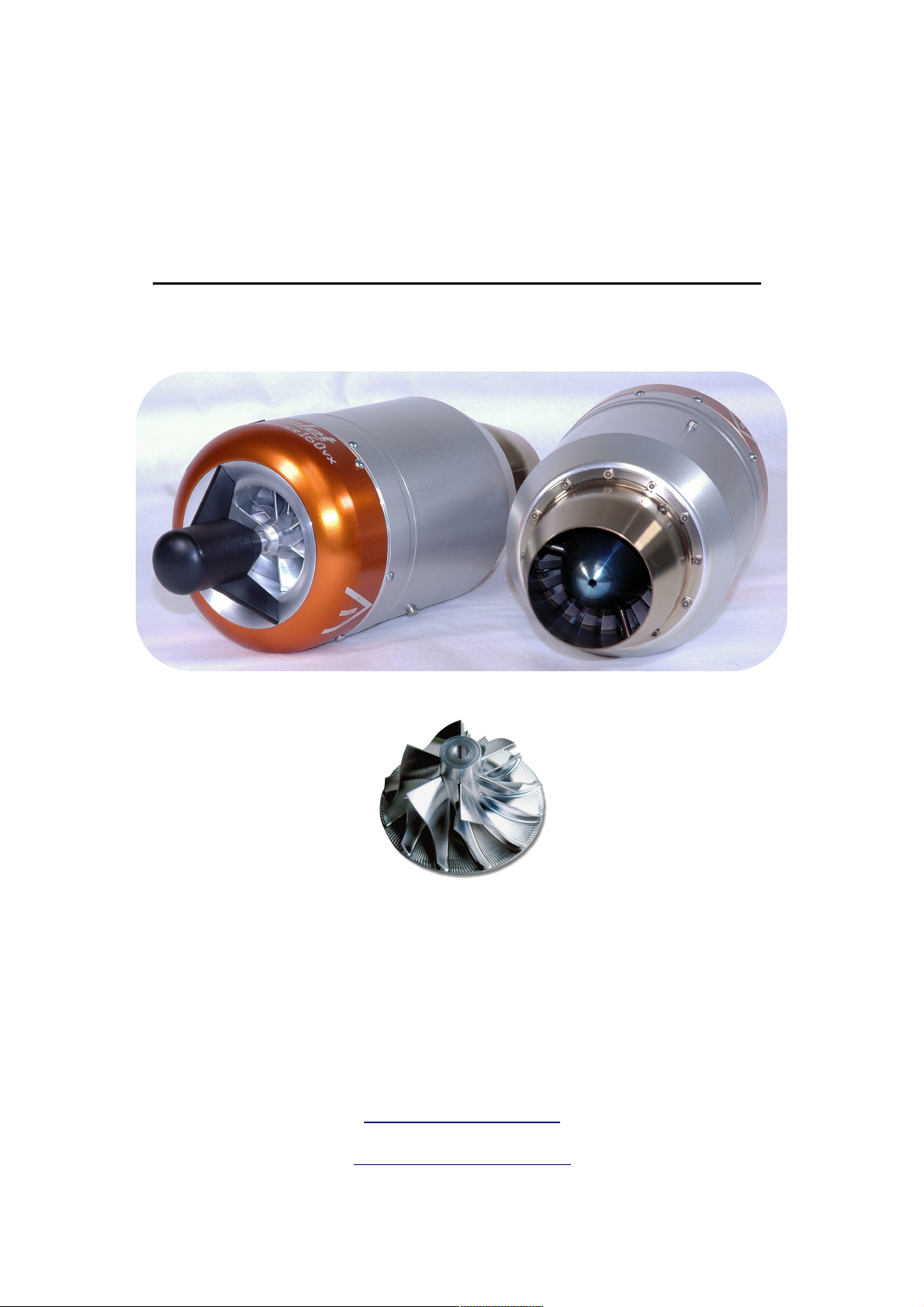
RC Model Jet Engines
evoJet - B90 - B130vx - B160vx
© 2005-2011 evoJet GmbH
Am Parir 4A
52379 Langerwehe – Germany
Tel.: +49 2423 / 401163 - Fax: 401217
http://www.evojet.de/
Page 2

evoJet B90 – B130vx – B160vx – Instructions 4.0
Contents
Introduction .........................................................................................................................3
Warnings and Safety Notes ...............................................................................................4
Warranty Conditions............................................................................................................7
Technical Specifications.....................................................................................................8
Installation Plan....................................................................................................................9
Checklist for the First Operation......................................................................................10
Checklist for Turning the Engine Off...............................................................................10
EDT Status Display (Engine Data Terminal)....................................................................11
JETRONIC-Vx – Firmware Setup......................................................................................13
1:INFO Menu ......................................................................................................................14
2:STATISTICS Menu ..........................................................................................................18
3:LIMITS Menu ...................................................................................................................20
4:AUTOSTART Menu ........................................................................................................22
5:R/C-SETTINGS Menu .....................................................................................................24
6:TEST-DEVICES Menu ....................................................................................................28
Airspeed Sensor [8135].....................................................................................................31
Notes...................................................................................................................................33
2
Page 3

evoJet B90 – B130vx – B160vx – Instructions 4.0
Introduction
The model jet engines of the evoJet-VX series uses the same functional principle as a "big" jet
engine. A high performance compressor compresses ingested air, which is then heated by a fuel
flame in the combustion chamber. The heat causes the air to expand rapidly, enabling it to drive an
axial turbine rotor, which in turn drives the aforementioned compressor via a shaft (open-circuit gas
turbine).
At the exhaust cone, the hot air leaves the engine at a speed of more than 1000 km/h (620 mph),
generating the required thrust for the jet aircraft model. An electric starter motor and a new electric
kerosene ignition system allow fully automated engine control from the R/C transmitter, controlled
and monitored by the JETRONIC control unit, which regulates all operating parameters to their
optimal values. This new generation of model jet engines does not require dangerous auxiliary
gases like propane or butane any more. Power is supplied to the engine by a separate
rechargeable lithium-manganese battery, which is used to power all system components, such as
fuel pump, kerosene ignition, valve etc.
State-of-the art precision CNC and laser cutting technology allow a previously impossible
production accuracy, ensuring both high performance and durability. The included display and
programming unit (EDT = Engine Data Terminal) is equipped with an illuminated LC-Display and
can be connected to (and disconnected from) the running system at any time to check the current
operating data or to change parameters. Besides the current operating parameters, such as
exhaust gas temperature (EGT), turbine revolutions per minute (rpm) and thrust (throttle),
additional information like total hours of operation, rpm and temperature statistics, number of
engine starts, battery voltage etc. can be displayed as well.
All parameters and user entries are displayed in plain text in a menu-based interface. The turbine
is started fully automatically via the throttle stick on the R/C transmitter. The pilot then adjusts the
desired thrust by moving the stick proptionally. The JETRONIC control unit is connected to the R/C
receiver via R/C-1. R/C-2 can be connected optionally for switching functions.
3
Page 4

evoJet B90 – B130vx – B160vx – Instructions 4.0
IMPORTANT NOTE:
Operating a jet aircraft model requires greatest care and special knowledge. When
installing and operating your jet engine, always observe the safety rules in this manual !
Warnings and Safety Notes
Welcome to the era of model jet aircraft! Please never forget: Operating a jet engine like the
evoJet-VX can be dangerous. An aircraft model equipped with the evoJet-VX can reach speeds of
more than 400 km/h (250 mph) and temperatures up to 500 °C (930 °F) at the engine housing and
up to 750 °C (1380 °F) at the exhaust jet. Since it is a genuine jet engine, it requires know-how,
discipline and regular service and maintenance – for your own protection and that of other people.
If you want to install and operate this jet engine in your model aircraft, you mus be trained in its
handling. The model with the jet engine should only be operated under supervision of an
experienced person, who can support you in order to avoid mistakes. If there is a local R/C club in
your area offering training and support, we recommend that you become a member. Mistakes
made during the assembly or operation of a jet-powered model aircraft can lead to serious injuries
or even death.
Always observe the law
Before operating a model aircraft with this jet engine, you should be informed about the legal
regulations regarding such aircraft. From a legal point of view, a model aircraft is considered an
aircraft like any other in most countries and is subject to the corresponding laws, which must be
observed by all means. Please check the applicable air traffic laws of your country carefully before
flying your model. Your local R/C club will likely be able to provide you with the required information and documents. In many countries, jet-powered model aircraft require a special licence
and/or a special insurance. Furthermore, regulations regarding the protection against interference
between R/C transmitters and radio networks must be observed. Please make sure to comply with
all applicable laws and regulations in your country.
CAUTION – keep a safe distance!
It is your responsibility to protect others against injuries. The operating distance of your aircraft
from residential areas must be at least 1.5 km (1 mile) in order to ensure the safety of people,
animals and buildings. Keep a safe distance from power lines. Never fly your model in bad weather
with low clouds or fog. Never fly directly against the sunlight – otherwise you might lose visual
contact with your model. To avoid collisions with manned or unmanned aircraft, land your model
immediately if an aircraft is approaching. Persons and animals must keep the following minimum
distance to the jet engine (see also the figure on page 6):
In front of the engine: 1 m (3 ft)
At the sides of the engine: 12 m (36 ft)
Behind the engine: 10 m (30 ft)
4
Page 5

evoJet B90 – B130vx – B160vx – Instructions 4.0
WARNING !
Operating the model and/or the jet engine under the influence of alcohol, drugs etc. is strictly
forbidden. The jet engine may only be handled by persons with an excellent physical and mental
condition and concentration. This applies to the operator as well as any assistants.
This jet engine was designed solely for use in model aircraft and is not suitable for any other
purpose. Never use it for persons, objects or vehicles other than suitably constructed model
aircraft, as any other use can lead to personal injury or death.
Any deviation from the specifications in this manual, the use of non-approved parts or materials or
modifications to the system construction or setup can have a negative effect on the functionality
and safety of the jet engine and must be avoided by all means.
WARNING !
The jet engine may only be operated in exact compliance with the instructions in this manual.
Furthermore, the specifications of the aircraft model regarding the centre of gravity and rudder
manipulations must be adhered to. The configuration recommended by the model manufacturer
must be observed. Before taking off with a model equipped with this jet engine, all functions and all
rudders as well as the range of the R/C transmitter must be tested with the transmiter turned on
and the antenna retracted. This range test must be repeated with the jet engine running while
another person is holding the model in place. Furthermore, the instructions by the R/C system
manufacturer must be followed closely.
Disclaimer
evoJet cannot supervise the adherence to the assembly and operating instructions for the aircraft
model and the jet engine, nor the installation, operation, use and maintenance of the model
components. Therefore, evoJet does not assume any liability for losses, damage or costs caused
by improper operation or improper behaviour or related in any other way to the aforementioned.
Unless demanded by law, any liability of evoJet to pay compensation for damages for whatever
reason (including personal injury, death, damage to buildings as well as loss of sales and profits,
business interruption or other indirect or direct consequential loss caused by the operation of the
model or the jet engine) is excluded. Under all circumstances and in any case, the joint liability is
limited to the amount you actually paid for the model aircraft or jet engine.
The operation of the aircraft model and the jet engine takes place solely at the operator's
own risk!
By operating the jet engine, you confirm to be aware of the fact that evoJet cannot supervise or
control the compliance with the instructions in this manual regarding assembly, operation and use
of the aircraft model, jet engine and remote control unit. From evoJet's side, no promises,
contractual agreements, guarantees or other agreements with persons or companies regarding the
functionality and operation of the model and the jet engine have been made. When buying this
aircraft model or jet engine, you as the operator were relying on your own expertise and
judgement.
5
Page 6

Safety Notes
Always have a fully functional CO2 fire extinguisher with at least 2 kg (4.4 lb) of filling
✔
weight at hand.
Only test the jet engine at suitable places outdoor and observe the applicable laws
✔
and regulations.
Always keep the following safety distances from the running jet engine
✔
(1 m = 3 ft, 10 m = 30 ft, 12 m = 36 ft):
evoJet B90 – B130vx – B160vx – Instructions 4.0
Never look straight into the exhaust jet and never touch it with your hands.
✔
Whenever possible, wear hearing protection.
✔
Keep away from the engine intake (electric starter). The air stream has an enormous
✔
suction power, which can lead to severe injuries.
After the first installation, and afterwards in regular intervals, test the transmission
✔
range of your R/C system with the jet engine running.
Before operating the engine, remove all loose objects near the engine intake, such
✔
as cleaning cloths, screws, nuts, cables or other material. Before operating your
model for the first time, make sure that there are no loose objects in the engine
intake, such as clippings, screws or swarf from building the model. Such objects can
damage the turbine. When installing the engine in your aircraft model, cover the
engine intake and exhaust opening, for example with adhesive tape, to keep
clippings/swarf and other objects from entering the engine.
Make sure that about 5 % of turbine oil is added to the fuel. Use prefered special
✔
aircraft turbine oil like AEROSHELL 500/560.
6
Page 7

evoJet B90 – B130vx – B160vx – Instructions 4.0
Warning:
Compared to an ducted fan model aircraft, the model with a real jet engine reaches much higher
airspeeds due to the considerably higher exhaust speed at the same static thrust. The achievable
airspeeds of more than 300 km/h (190 mph) normally exceed the speed range an aircraft model is
approved for (risk of rudder flutter, sudden nose dives and overload of the fuselage and the
servos).
Therefore always take care of the following: After taking off and accelerating to normal airspeed,
always pull the throttle back. For horizontal flight, 50 % of thrust is sufficient to achieve the same
flight performance as with an ducted fan !
Only use the full thrust of the jet engine for takeoff and for vertical climbing in aerobatics!
For limiting the airspeed, we highly recommend using the optionally available Airspeed Sensor
(part no. 8135) !
Warranty Conditions
The warranty covers the free repair or replacement of parts that exhibit proven defects of
fabrication or material defects within the warranty period from the date of purchase. Any further
claims are excluded. Costs for packaging and shipping are paid by the buyer. No liability is
assumed for loss during transport. When sending the defective article to evoJet or to the
service contractor in charge for the respective country, a detailed description of the fault and the
invoice stating the date of purchase must be included. The warranty is void if the defect of the
part or the model is caused by an accident, improper handling or improper use.
7
Page 8

evoJet B90 – B130vx – B160vx – Instructions 4.0
Technical Specifications
evoJet B90 – B130vx – B160vx
Max. thrust: B90: typ. 9 kg = 19 lb
B130: typ. 14 kg = 31 lb
B160: typ. 16 kg = 36 lb
Diameter: B90: 91 mm = 3.6 inches
B130/160: 112 mm = 4.4 inches
Length incl. starter: B90: 230 mm = 9.06 inches
B130/160: 288 mm = 11.3 inches
Weight: B90: 950 g = 2.1 lb
B130: 1595 g = 3.52 lb
B160: 1620 g = 3.58 lb
Rotor speed: B90: 45.000 – 165.000 rpm
B130: 30.000 – 119.000 rpm
B160: 30.000 – 123.000 rpm
Compressor: Alloy 2618 compressor 12-blade
Turbine: Axial-wheel Inconel
Fuel consumption: B90: max. 285 g = 10.0 oz./min.
B130: max. 420 g = 14.8 oz./min.
B160: max. 520 g = 18.4 oz./min.
Fuel type: Jet A1 / kerosene, approved fuel
with 5 % oil
Maintenance interval: B90: 300.000.000
B130/160: 200.000.000
corresponding 50 hours, see 24:JET-ENGINE
(page 19)
Status: October - 2010
(*) The engine thrust is electronically adjustable by setting the idle- and the full
thrust revolution speed (page 21, 30:ENGINE-IDLE und 31:ENGINE-100% ). All
performance data are related to International Standard Atmosphere, ISA and
optimal operating conditions which means, fuel, thrust tube and sufficient air
supply.
8
Page 9
Installation Plan
evoJet B90 – B130vx – B160vx – Instructions 4.0
9
Page 10

evoJet B90 – B130vx – B160vx – Instructions 4.0
Checklist for the First Operation
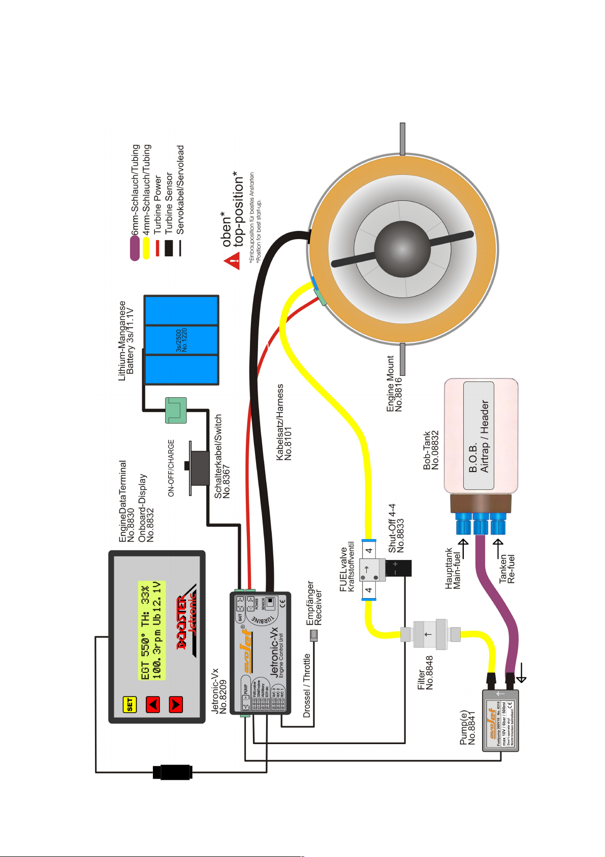
Install and connect the components according to the installation plan (see page 9). Pay
✔
special attention to the correct connection of the FUELvalve and to a proper laying of the
tubes without kinking them. An arrow on the fuel pump and the valve indicates the flow
direction to the engine.
The QS quick connectors (blue) should snap in when you plug in the tube. The tube can
✔
only be released by pressing on the blue ring while pulling the tube out. Only use approved
PUN tubes with a diameter of 3 mm (0.12") or 4 mm (0.16"), respectively.
Check the temperature sensor to the environment temperature via the parameter
✔
AUTOSTART 47:EGT/AMBIENT (see page 23).
Teach-in the remote control: OFF, IDLE, 100 %, via the R/C-SETTINGS parameters 51, 52,
✔
53 (see page 25).
Charge all batteries, paying special attention to the correct charging program for the lithium-
✔
manganese battery, i.e. a maximum charging voltage of 12.6 V. Use the 3s LiPo charging
mode with 1 – 2 Amps.
Open the fuel tank ventilation, then fill the fuel tank(s) with fuel containing approx. 5 % of
✔
oil, i.e. one can of turbine oil in 20 litres (5.3 US gallons) of kerosene.
Have a CO2 fire extinguisher at hand!
✔
Turn on the R/C transmitter, then turn on the receiver.
✔
Place your aircraft model with the nose against the wind.
✔
Start the jet engine (keep a safe distance, see page 6!):
✔
1. Throttle down + trim down => remove LOCK
2. Trim up => RUN – cleared
3. Throttle up and down again => AUTOSTART activated, see EDT display (page 11).
Checklist for Turning the Engine Off
Place the aircraft model with the nose against the wind.
✔
Turn the jet engine off: Throttle down + trim down (below 25%) => -OFF
✔
Wait until the automatic cool-down procedure of the engine is finished.
✔
Check the INFO data about the operating states (see page 14 ff).
✔
After finishing the flight activities, remove all fuel from the tank(s) and close the fuel tank
✔
ventilation.
10
Page 11

evoJet B90 – B130vx – B160vx – Instructions 4.0
EDT Status Display (Engine Data Terminal)
= Throttle is a combined function display and error display for the engine operation.
TH:
Use the Up/Down keys to select different display values:
Ub11.8V
FP 2.1V
0km/h
0.00rpm
Function display – example for a standard start-up procedure:
TH:lock
TH:stop
TH:run-
→ current battery-Voltage.
→ current fuel-pump-Voltage.
→ current air-speed display in km/h (for telemetrie).
→ current rotor-/propeller-speed (rpm).
→ Remote control locked – to unlock it, pull the throttle and the trim
all the way back. See also 51:RC1-TRIM.OFF (page 25).
→
→
Remote control unlocked – engine off – to turn it on, push the trim up.
See also 52:RC1-IDLE (page 25).
Engine on – for a further check, push the throttle forward.
See also 53:RC1-100% (page 25).
TH:rel-
TH:fire
→
→
Check complete – to start the turbine, pull the throttle back to the IDLE
position within 10 seconds.
The fuelpump confirms the starting procedure with a short burst.
Preheating of the kerosene igniter, this takes about 5 to 15 seconds.
11
Page 12

evoJet B90 – B130vx – B160vx – Instructions 4.0
TH:spin
TH:heat
TH:acce
TH:cal.
→
→
→
→
TH:idle100%
TH:-off
TH:cool
→
→
Spin-up via the electric starter and fuel ignition.
See also 40:SPINUP/FIRE (page 23).
Heat-up phase of the kerosene igniter and the combustion chamber.
See also 44:HEAT-UP (page 23).
Acceleration of the turbine to normal operation.
See also 43:ACCE-RAMP (page 23).
Calibration of the fuel pump and the fuel supply system.
Thrust available to the pilot. Ready for takeoff!
To turn off the engine, pull the throttle and the trim all the way back.
The engine enters a controlled cool-down phase to ensure a long life of the
high-performance bearings.
The error codes are explained under Firmware Setup 19:LAST-OFF on page 16/17.
Notice:
To learn-in a new fuel-system, let the jet engine run at least for 10 seconds at full speed
(max-rpm).
Attention:
Dont do exessive full-throttle ground runs in the airplane withour sufficient air supply !
12
Page 13
evoJet B90 – B130vx – B160vx – Instructions 4.0
JETRONIC-Vx – Firmware Setup
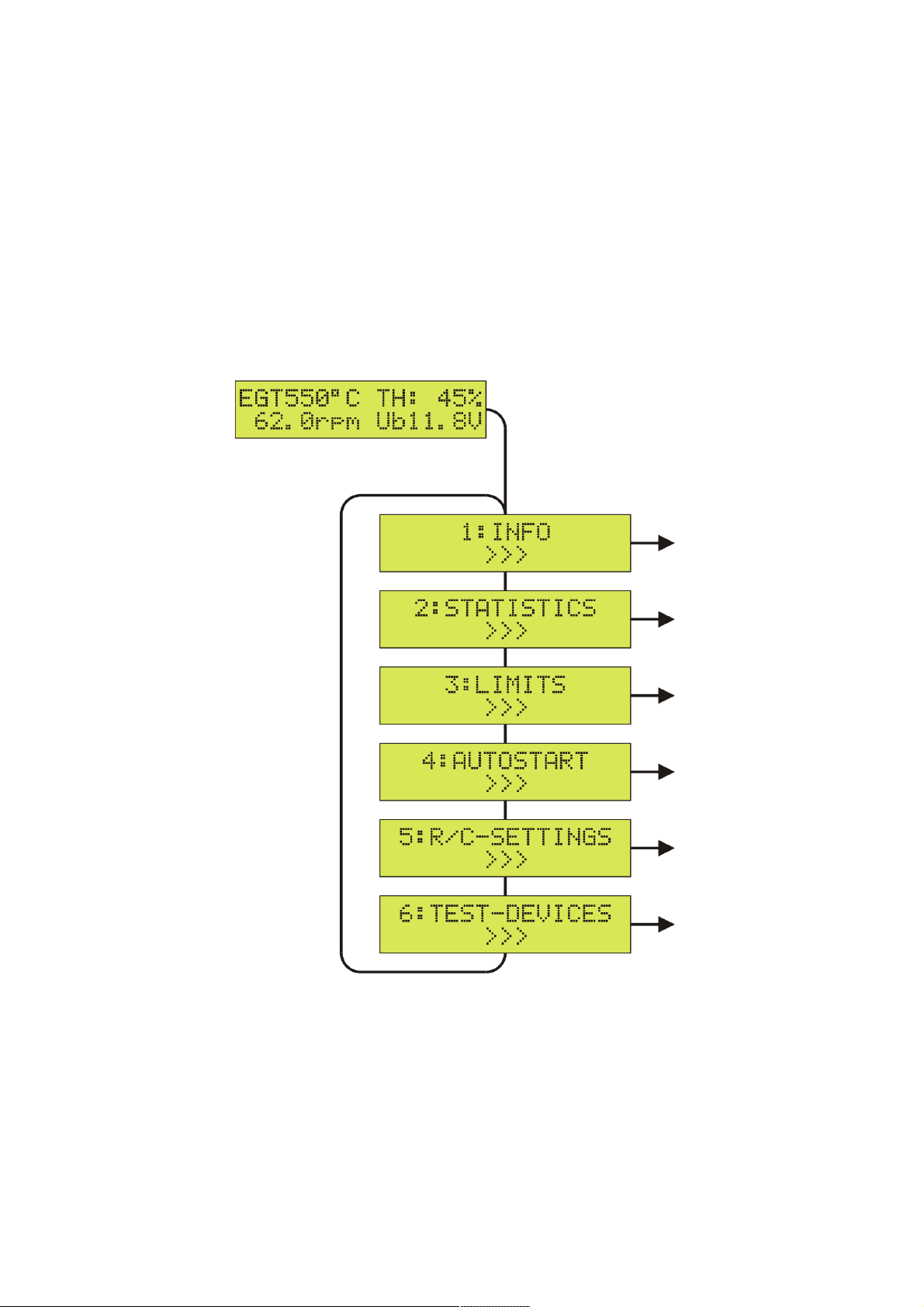
SETUP Menu
To enter the SETUP menu for configuring the firmware parameters, first press the SET key and
then use the Up/Down keys to switch between the available parameter sections.
To quit the SETUP menu and to return to the operating status display, press the SET key for
more than 2 seconds (ESC). In the following, the individual submenus of the SETUP menu are
described.
13
Page 14
evoJet B90 – B130vx – B160vx – Instructions 4.0
1:INFO Menu
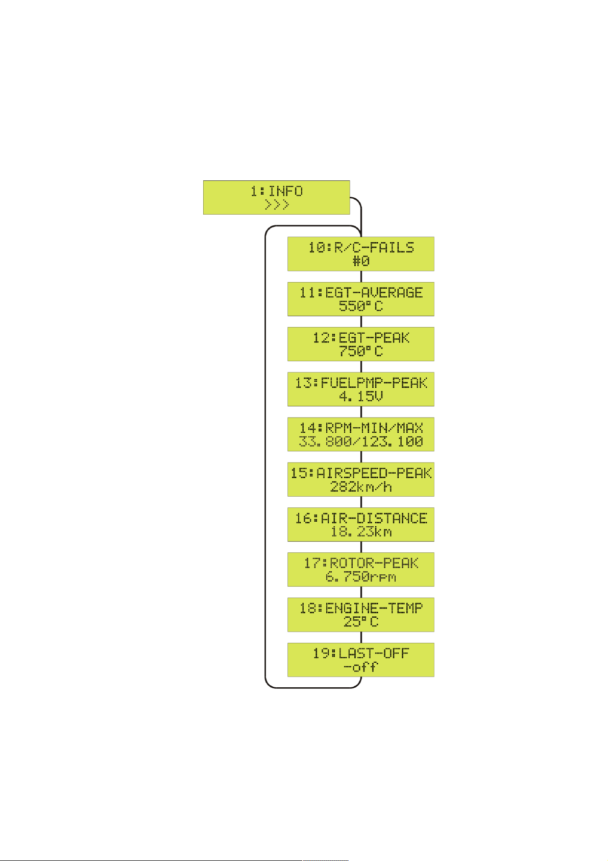
To enter the 1:INFO menu, first press the SET key and then use the Up/Down keys to switch
between the available parameters.
To quit the 1:INFO menu and to return to the SETUP menu, press the SET key for more than 2
seconds (ESC).
The operating status display appears automatically after 20 seconds, or press the SET key for
more than 2 seconds (
>>>
changes to
<<<
, ESC).
14
Page 15

evoJet B90 – B130vx – B160vx – Instructions 4.0
1:INFO – Operating Status Information
10:R/C-FAILS
indicates the number of R/C failsafes (failures of the remote control connection) that lasted longer
than one second during the last engine run. Normally this parameter should be #0, i.e. no failsafes.
If the number is frequently greater than #0, you should check your remote control system.
Do a Radio-Control range test !
11:EGT-AVERAGE
shows the average exhaust gas temperature during the last engine run. Typical values after a flight
should be between 500 and 680 °C. Higher values might be caused by an unsuitable exhaust duct
or insufficient ventilation to the turbine.
12:EGT-PEAK
shows the maximum exhaust gas temperature that occurred during the last engine run. This value
is normally reached only briefly during the acceleration of the turbine until the higher revolution
speed is reached. Typical values can be up to 850 °C.
13:FUELPMP-PEAK
shows the highest fuel pump voltage during the last engine run. A “!“ after the "V" means
that the maximum allowed pump voltage specified under LIMITS 33:FUELPMP-MAX has been
reached. The maximum pump voltage is a good indicator for the quality (flow resistance) of the
entire fuel supply system. An continuously increasing pump voltage after the flights may be caused
by a plugged filter or fuel clunk.
14:RPM-MIN/MAX
shows the lowest and the highest revolution speed of the turbine during the last engine run.
Normally, this value should match the rpm values specified under LIMITS 30:ENGINE-idle and
LIMITS 31:ENGINE-100% in the variation of (±300rpm). If the 100 % thrust rpm value has not
been reached, the reason might be a kinked fuel tube or a plugged filter or fuel clunk. It is also
possible that the maximum fuel pump voltage specified under LIMITS 33:FUELPMP-MAX is set too
low.
15:AIRSPEED-PEAK
shows the maximum airspeed during the last flight. This requires the Airspeed-Sensor [8135] to be
installed and the parameter 59:AUX-MODE to be set to AIRSPEED.
16:AIR-DISTANCE
shows the distance covered during the last flight. This requires an airspeed sensor to be installed
and the parameter 59:AUX-MODE to be set to AIRSPEED.
17:ROTOR-PEAK
shows the maximum revolution speed of the propeller/rotor during the last engine run.
See also LIMITS 38:ROTOR-MAX.
18:ENGINE-TEMP
shows the current temperature under the turbine cover in °Celsius.
15
Page 16

evoJet B90 – B130vx – B160vx – Instructions 4.0
19:LAST-OFF
shows the reason or error causing the engine shutdown:
-off
R/C!
noID
badG
Solution: Charge the turbine battery and/or check the cables and plugs.
main
strR
Regular switchoff of the engine via the R/C transmitter or via the SET key in the case of a
manual test run without remote control.
Same as -off regular switchoff, but with a hint as to counted radio failsafes.
See 10:R/C-FAILS, failures of the remote control connection.
Solution: Check the remote control system and do a transmission range test!
The engine is not detected or is not connected.
Solution: Turn the JETRONIC off and on again and/or check the cables and plugs.
The glow plug is defective or too cold. This error can also be caused by a weak or empty
turbine battery.
Internal hardware error, overheating or bad contacts
Solution: Let the JETRONIC unit cool down and/or check the cables and plugs.
The starter motor does not deliver suffucient power to continue the starting procedure.
Solution: Charge the turbine battery and/or check the cables and plugs.
It is also possible that the clutch rubber of the starter is oily or worn out. Carefully clean it
with a cotton bud and glass cleaning agent.
- error codes,
minR
minT
maxT
➔
➔
➔
time
The revolution speed falls below the required value during the startup procedure. This
is usually caused by air bubbles in the fuel supply system leading to a flameout in the
combustion chamber.
Solution: Make sure that the fuel supply is sufficient and uninterrupted.
The exhaust gas temperature falls below the value specified under LIMITS 34:EGT-MIN.
This is usually caused by air bubbles in the fuel supply system leading to a flameout in the
combustion chamber. Accompanied by considerable smoke emissions.
Solution: Use a better fuel tank system with a membrane fuel clunk or an AirTrap tank.
The exhaust gas temperature exceeds the value specified under LIMITS 36:EGT-OFF.
Reasons may be:
Large air bubbles in the fuel supply system
A fuel puddle in the turbine
Solution: Hold a cloth against the engine intake and tilt the engine or the aircraft model
upright with the intake facing down, so the fuel flows out of the engine into the cloth.
Caution: Take care not to pollute the starter motor and/or the clutch!
The clutch rubber of the starter motor is oily or worn out.
Solution: Carefully clean it with a cotton bud and glass cleaning agent.
The time limit for the startup procedure is exceeded.
Probably a fuel tube is kinked or plugged.
Solution: Check the laying of the fuel tubes and the fuel tank.
ovrR
The revolution speed exceeds the value specified under LIMITS 31:ENGINE-100%. This is
usually caused by air bubbles in the fuel supply system.
Solution: Use a better fuel tank system with a membrane fuel clunk or an AirTrap tank.
16
Page 17

evoJet B90 – B130vx – B160vx – Instructions 4.0
runR
lowB
higB
R/C?
tolF
The revolution speed falls below the value specified under LIMITS 33:ENGINE-MIN. This
is usually caused by air bubbles in the fuel supply system leading to a flameout in the
combustion chamber. Accompanied by considerable smoke emissions.
Solution: Use a better fuel tank system with a air-membrane fuel clunk or an AirTrap tank.
Solution: Increase the LIMITS: 33THROTTL-UP e.g. to 5 sec's !
The minimum voltage of the turbine battery has been reached and the safety limitation has
been activated (throttle can only up to 50 %, lowB). To receipt this, immediately throttle
down to idle and land the airplane. If the minimum system voltage is reached, a safety
shutoff takes place (lowB, lowB).
Solution: Charge the turbine battery and/or check the cables and plugs.
An overvoltage of the turbine battery has been detected.
Solution: Check the turbine battery, connect the right battery type and/or check the
AUTOSTART 46:BATTERY battery type settings.
The RC1 remote control signal was not detected for a longer time than specified under
R/C-SETTINGS 57:FAILS-TIME, or the RC2 remote control signal was not detected for
more than one second.
Solution: Check the remote control system and do a transmission range test!
The sensors of the engine deliver invalid measurement signals. This means that the engine
can no longer be controlled and must be shut down (safety shutoff).
Solution: Charge the turbine battery and/or check the cables and plugs.
The trim down (below 50%=mid) removes the error codes and enables the jet engine again:
Restart the jet engine (keep a safe distance, see page 6!):
1. Throttle down + trim down (below 50%) => remove LOCK
2. Trim up => RUN – cleared
3. Throttle up and down again => AUTOSTART activated, see EDT display (page 11).
17
Page 18

evoJet B90 – B130vx – B160vx – Instructions 4.0
2:STATISTICS Menu
To enter the 2:STATISTICS menu, first press the SET key and then use the Up/Down keys to
switch between the available parameters.
To quit the 2:STATISTICS menu and to return to the SETUP menu, press the SET key for more
than 2 seconds (ESC).
The operating status display appears automatically after 20 seconds, or press the SET key for
more than 2 seconds (
>>>
changes to
<<<
, ESC).
18
Page 19

evoJet B90 – B130vx – B160vx – Instructions 4.0
2:STATISTICS – Display of Operating Statistics
20:RUNS-TOTAL
shows the total number of engine runs or engine starts so far.
Unit: #
21:START-ABORT
shows the total number of aborted engine starts.
Unit: #
22:RUNS-ABORT
shows the total number of aborted engine runs where PWR shows the number of power-failures.
Unit: # PWR:#
23:HOUR-METER
shows the total operating time of the jet engine resp. the fuel pump.
Unit: HH:MM'SS
24:JET-ENGINE
shows the identification, serial number and lifetime of the connected jet engine.
Unit: ID SERIAL LIFE
B160#09123# 1.50
type year+serial lifetime
The lifetime value indicates the total number of turbine revolutions in millions.
A ! after the serial number means "stored value", for example with no engine connected.
25:RECORDER
shows the memory amount of the recorder unit.
Unit: record-kb (total-kb)
26:FIRMWARE
shows the info string of the current firmware with the version number.
19
Page 20
evoJet B90 – B130vx – B160vx – Instructions 4.0
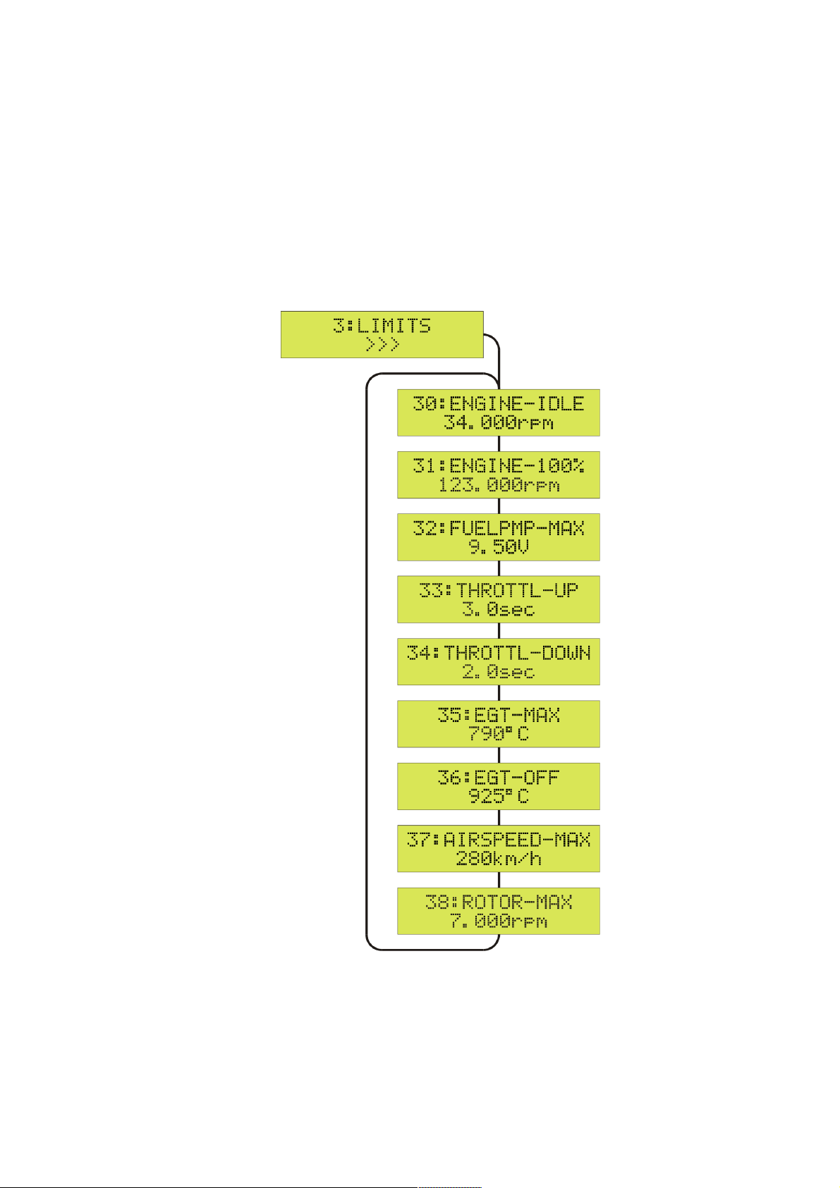
3:LIMITS Menu
To enter the 3:LIMITS menu, first press the SET key and then use the Up/Down keys to switch
between the available parameters.
To change a setting, first press the SET key and then use the Up/Down keys to switch between the
available values. A ? indicates the value to be set. To finish the setting and store the new value,
press the SET key again.
To quit the 3:LIMITS menu and to return to the SETUP menu, press the SET key for more than 2
seconds (ESC).
The operating status display appears automatically after 20 seconds, or press the SET key for
more than 2 seconds (
>>>
changes to
<<<
, ESC).
20
Page 21

evoJet B90 – B130vx – B160vx – Instructions 4.0
3:LIMITS – Adjusting the evoJet Engine
CAUTION: Do not change any settings in the LIMITS menu unless you know exactly
what effect the respective change will have! Wrong settings can lead to serious
problems during the operation of your jet engine.
30:ENGINE-IDLE
This parameter specifies the idle revolution speed when the throttle is in the idle position.
Recommend values B90: 50.000 rpm B130/B160: 34.000 rpm
31:ENGINE-100%
This parameter specifies the full thrust revolution speed (100 %) when the throttle is in the full
thrust position.
Standard values B90: 160.000 rpm B130: 117.000 rpm B160: 120.000 rpm
If this setting is changed, the INFO parameters 13:EGT-PEAK, 14:FUELPMP-PEAK and
15:RPM-PEAK are reset.
32:FUELPMP-MAX
This parameter specifies the maximum allowed voltage [V] for the fuel pump.
Standard values B90: 5.5 Volt B130: 8.5 Volt B160: 9.9 Volt
If this setting is changed, the INFO parameters 14:FUELPMP-PEAK and 15:RPM-PEAK are reset.
33:THROTTL-UP
This parameter specifies the acceleration/throttle-up time (more thrust) of the engine.
Recommend values B90: 4.0 sec B130/B160: 3.0 sec
34:THROTTL-DOWN
This parameter specifies the deceleration/throttle-down time (less thrust) of the engine.
Standard values B90: 3.4 sec B130/B160: 2.0 sec
35:EGT-MAX
This parameter specifies the maximum exhaust gas temperature for the engine control.
Standard value: 790 °C (1454 °F)
36:EGT-OFF
This parameter specifies the exhaust gas temperature for a safety break during the startup.
Standard value: 840 °C (1700 °F)
37:AIRSPEED-MAX
This parameter specifies the maximum allowed airspeed, above which the thrust of the engine is
automatically reduced. To use this function, set 59:AUX-MODE to AIRSPEED (enables the
AIRSPEED-SENSOR [8135]) and maybe set 54:RC2-MODE to AIRSPEED (RC2 switches the
limiting OFF/ON from the Radio). If RC2-MODE = AIRSPEED is not used the limiter is default ON.
Standard value: 250 km/h (155 mph)
This function requires the Airspeed-Sensor (part no. 8135) to be installed. See page 31.
38:ROTOR-MAX
This parameter specifies the propeller/rotor revolution speed for turboprop and helicopter.
21
Page 22

evoJet B90 – B130vx – B160vx – Instructions 4.0
4:AUTOSTART Menu
To enter the 4:AUTOSTART menu, first press the SET key and then use the Up/Down keys to
switch between the available parameters.
To change a setting, first press the SET key and then use the Up/Down keys to switch between the
available values. A ? indicates the value to be set. To finish the setting and store the new value,
press the SET key again.
To quit the 4:AUTOSTART menu and to return to the SETUP menu, press the SET key for more
than 2 seconds (ESC).
The operating status display appears automatically after 20 seconds, or press the SET key for
more than 2 seconds (
>>>
changes to
<<<
, ESC).
22
Page 23

evoJet B90 – B130vx – B160vx – Instructions 4.0
4:AUTOSTART – General Startup Settings
CAUTION: Do not change any settings in the AUTOSTART menu unless you know
exactly what effect the respective change will have! Wrong settings can lead to serious
problems during the operation of your jet engine.
40:SPINUP/FIRE
This parameter specifies the revolution speed at which the ignition takes place during the spin-up
of the turbine.
Standard value B90: 3.100 rpm B130/160: 2.900 rpm
41:BURNER-MAX
This parameter specifies the revolution speed at which the start burner is switched off.
Standard value B90: 9.000 rpm B130/B160: 8.000 rpm
42:STARTER-MAX
This parameter specifies the maximum revolution speed for the electric starter.
Standard value B90: 32.000 rpm B130/B160: 28.000 rpm
43:ACCE-RAMP
This parameter specifies the time for the acceleration ramp.
Standard value: 16 seconds
44:HEAT-UP
This parameter specifies the time for the combustion chamber heating phase.
Standard value: 3 seconds
45:GLOWPLUG
This parameter specifies the voltage [V] for the glow plug.
Standard value : 11.0 Volt
46:BATTERY
This parameter specifies the type of supply battery (battery low detection).
Standard value: Li3s (11.1 V)
Possible are:
Ni: 10-cells(12V) - NiCd/NiMh (min. SUB-C 2400/3000 size)
Li: 3s-cells(11.1V) - LithiumMangan/LiPo min. 20C
A123: 4s-cells(13.2V) - A132 Lithium-Eisen
Only use approved turbine batteries with sufficient capacity and high-current, such as the lithiummanganese batteries.
47:EGT/AMBIENT
Use this parameter to adapt the temperature sensor (EGT zero point) to the current ambient
temperature e.g. 21 °C (@ 70 °F)
48:BURNER-GLOW
This parameter specifies the minimum preheattime for the electrical burner.
Standard value: 14 seconds
In the cold period where battery voltage and fuel temperature are low, an increase of the minimum
burner preheattime to i.e. 22 seconds may improve the engine startup performance.
23
Page 24

evoJet B90 – B130vx – B160vx – Instructions 4.0
5:R/C-SETTINGS Menu
To enter the 5:R/C-SETTINGS menu, first press the SET key and then use the Up/Down keys to
switch between the available parameters.
To change a setting, first press the SET key and then use the Up/Down keys to switch between the
available values. A ? indicates the value to be set. To finish the setting and store the new value,
press the SET key again.
To quit the 5:R/C-SETTINGS menu and to return to the SETUP menu, press the SET key for more
than 2 seconds (ESC).
The operating status display appears automatically after 20 seconds, or press the SET key for
more than 2 seconds (
>>>
changes to
<<<
, ESC).
24
Page 25

evoJet B90 – B130vx – B160vx – Instructions 4.0
5:R/C-SETTINGS – Adapting the JETRONIC Unit to your R/C System
CAUTION: Do not change any settings in the R/C-SETTINGS menu unless you know
exactly what effect the respective change will have! Wrong settings can lead to serious
problems during the operation of your jet engine.
In the standard setup, RC1 is used for the throttle and the trim is used as an ON/OFF switching
function. You can also use RC2 as an additional ON/OFF safety switch. The remote control signals
RC1 and RC2 must have a positive servo travel way, i.e. short pulses (-100 %) for OFF or IDLE
and long pulses (+100 %) for ON or 100 % / full thrust. This complies with the JR/evoJet standard
setting. For Futaba or Multiplex transmitters, you may have to use the servo reverse switch.
The parameters printed in blue (51, 52, 53) are necessary settings to be made before the
first operation of the jet engine!
50:R/C-MONITOR
shows the current signals at the RC1 and RC2 inputs. For RC1 (throttle), the current throttle/thrust
setting is displayed:
NO = no signal
LOCK = throttle and trim OFF = 51:RC1-TRIM.OFF or FAILSAFE detected.
FAIL = throttle and trim are below the 51:RC1-TRIM.OFF or above the 53:RC-1-100%
settings. FAILsafe detection !
0-100% = throttle / thrust in % between 52:RC1-IDLE and 53:RC1-100%
In addition to the trim signal, the RC2 input can be used as a safety switch. To do so, set the parameter 54:RC2-MODE to SAFETY.
NO = no signal
OFF = OFF signal (-100 %)
ON = ON signal (+100 %) = unlocked
51:RC1-TRIM.OFF
Teach-in the RC1 signal for the position "engine = OFF" (shortest pulse). Activate the teach mode
with the SET key. The new pulse length is shown on the display. Use the throttle stick to checkout
the pulse lenght value. Move the throttle and the trim to the OFF position (throttle and trim all the
way back). To finish the adjustment and store the new value, press the SET key again.
Standard value: 1.00 ms
52:RC1-IDLE
Teach-in the RC1 signal for the position "engine = IDLE" (trim forward, throttle all the way back).
The new pulse length is shown on the display. To finish the adjustment and store the new value,
press the SET key again.
Standard value: 1.25 ms
25
Page 26

evoJet B90 – B130vx – B160vx – Instructions 4.0
53:RC1-100%
Teach-in the RC1 signal for the position "engine = 100 % / full thrust" (longest pulse). Activate the
teach mode with the SET key and move the throttle to the 100 % / full thrust position (trim and
throttle all the way forward). The new pulse length is shown on the display. To finish the
adjustment and store the new value, press the SET key again.
Standard value: 2.00 ms
54:RC2-MODE
Selecting the RC2 signal function
Standard value: OFF
OFF = control only via RC1 (throttle and trim).
SMOKE-VALVE
= switching function for a smoker valve 5V/100mA connected to the AUXiliary port
OFF = -100%, ON = +100%.
For this set 59:AUX-MODE to SMOKER-VALVE. The smoker function is enabled
when the turbine is running or when using the testfunction 65:SMOKER-RC2.
AIRSPEED = switching function for the airspeed limiter
OFF = -100%, ASL(AirSpeedLimiter) = +100%
see also 37:AIRSPEED-MAX and 59:AUX-MODE.
SMOKE-PUMP
= switching function for a smokepump connected to the RC3 terminal.
OFF = -100% =>55:RC3-LOW / ON = +100% =>56:RC3-HIGH
At 55: the OFF and at 56: the full power is adjustable.
The smoker function is enabled when the turbine is running or when using the
testfunction 65:SMOKER-RC2.
26
Page 27

evoJet B90 – B130vx – B160vx – Instructions 4.0
55:RC3-LOW
Adjusting the LOW-signal for the RC3-output.
Standard value: -100%
56:RC3-HIGH
Adjusting the HIGH-signal for the RC3-output.
Standard value: +100%
57:FAILS-TIME
Adjusting the hold time for the RC1 signal in the case of a remote control failure (failsafe).
If the RC1 signal is out the range between the values defined at 51:RC1-TRIM.OFF and 53:RC1100%, a remote control failure (failsafe) is detected. During the time specified here, the JETRONIC
will automatically set the throttle to the value defined at 58:FAILS-THROTTL.
If the failsafe state persists after this time has elapsed, the jet engine is switched off automatically.
Standard value: 5 seconds
58:FAILS-THROTTL
Adjusting the thrust level in the case of an RC1 signal failure (failsafe)
Standard value: 20 %
59:AUX-MODE
Selecting the AUXiliary function / connection to the JETRONIC - AUX
OFF = no function
AIRSPEED = airspeed sensor connected, 37:AIRSPEED-MAX active!
WARN-LED = Low rpm / overheating indicator with external LED
SMOKER-VALVE
= A smoker valve 5V/100mA can be connected.
5A:THROTTL-TYPE
Selecting the throttle transferfunction for the engine speed (throttlecurve).
SOFT = The Throttle works rpm-linear, e.g. softer in the lower rpm range.
Better for smaller and lighter airplanes.
HARD = The Throttle works thrust-linear, e.g. quicker in the lower rpm range.
Better for bigger and heavy airplanes.
27
Page 28
evoJet B90 – B130vx – B160vx – Instructions 4.0
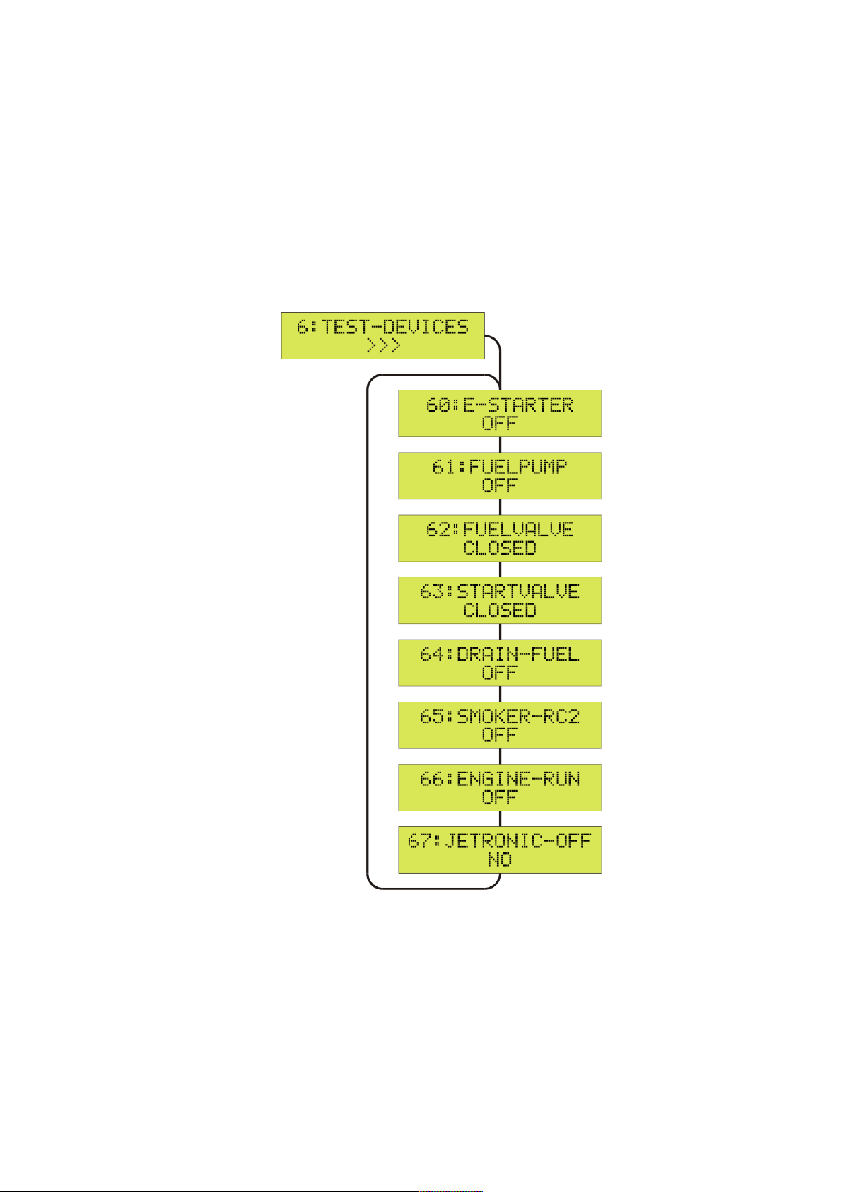
6:TEST-DEVICES Menu
To enter the 6:TEST-DEVICES menu, first press the SET key and then use the Up/Down keys to
switch between the available test functions.
To activate a test function, first press the SET key and then use the Up/Down keys to test the
individual system components (devices). A ? indicates the value to be set. To finish the test, press
the SET key again.
To quit the 6:TEST-DEVICES menu and to return to the SETUP menu, press the SET key for more
than 2 seconds (ESC).
The operating status display appears automatically after 20 seconds, or press the SET key for
more than 2 seconds (
>>>
changes to
<<<
, ESC).
28
Page 29

evoJet B90 – B130vx – B160vx – Instructions 4.0
6:TEST-DEVICES – Checkout system components
The parameters printed in blue are important tests that should be done before the first
operation of the jet engine!
60:E-STARTER
Manual operation of the electric starter with the Up/Down keys
The starter motor should accelerate the turbine to 2000 rpm for at least 3 seconds.
Standard value: OFF
61:FUELPUMP
Manual operation of the fuel pump with the Up/Down keys
The FUELvalve can be opened too for priming the fuelline - just push both buttons simultaneous
and take care not to flood the engine !
Standard value: OFF
62:FUELVALVE
Manual opening of the FUELvalve with the Up/Down keys
It must be connected to the left socket-pins at the JETRONIC (FUELvalve).
Standard value: CLOSED
63:STARTVALVE
Not neccessary with evoJet-VX engines.
Standard value: CLOSED
64:DRAIN-FUEL
Use this function to pump the fuel back from the engine into the fuel cells. For this purpose, the fuel
pump is running backwards and both fuel valves are activated. This function is useful if you want to
store your model for a longer period or make modifications to it.
Standard value: OFF
65:SMOKER-RC2
Manually enabling the smokerfunction for a test with RC2. For this press the Up/Down key.
Standard value: OFF – OPEN
29
Page 30

evoJet B90 – B130vx – B160vx – Instructions 4.0
66:ENGINE-RUN
Starting and testing the jet engine without the remote control
Activate the test run with the Up key (ON) and press the SET key to switch to the operating status
display:
The throttle/thrust display now shows -rel (release) and waits for your clearance with the Down
key: The fully automatic starting prodecure is activated.
Operation: You can stop the test run at any time with the SET key (like an emergency switch).
With the Up/Down keys, you can adjust the thrust between IDLE and 100 % (similar
to the R/C throttle).
CAUTION: Please keep in mind that a stationary test run of the jet engine can lead to
very high temperaures in the aircraft model (exhaust duct) due to the reduced airflow.
67:JETRONIC-OFF
Manual switching of the JETRONIC to energy saving mode (sleep mode)
Press the Up key to activate the sleep mode (YES) and turn off directly with the SET key.
Standard value: NO
The JETRONIC is automatically switched to sleep mode if the following is true for a period of at
least 4 minutes:
No RC1 signal is present,
✗
cooling down is finished and
✗
no keys are pressed.
✗
By switching the R/C transmitter on (RC1 signal), the JETRONIC is activated again. In sleep mode
the current consumption is 1,3mA only, which is about 1 month by an battery charge of 1000mAh.
30
Page 31
evoJet B90 – B130vx – B160vx – Instructions 4.0
Airspeed Sensor [8135]
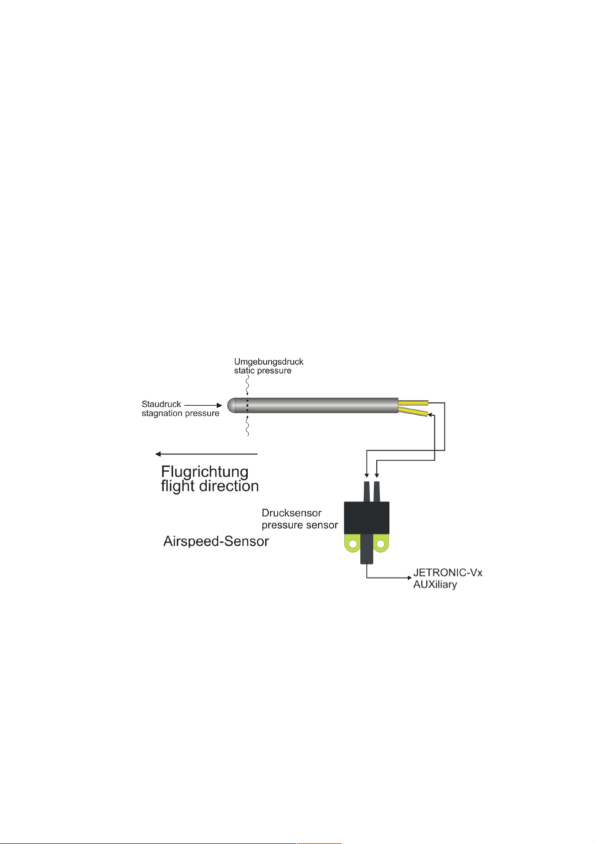
The JETRONIC-Vx allows the connection of an optional airspeed sensor to the AUXiliary connector. For the measurement, a pitot tube (Prandtl type) and an electronic pressure sensor are
used. The tube is mounted on the outside of the model in flight direction and the sensor is mounted
inside the model. The two components are connected via the two included pieces of tubing.
The measurement of the airspeed in flight allows several useful functions:
Determining the (maximum) airspeed [km/h] (see INFO:15 AIRSPEED-PEAK)
●
Determining the covered total distance [km] flown (see INFO:16 AIR-DISTANCE)
●
Limiting the airspeed to a value allowed for the airframe model
●
(always or switchable).
Installation
Activation
Set R/C-SETTINGS:59 AUX-MODE to AIRSPEED.
✔
Set LIMITS:37 AIRSPEED-MAX to the desired speed in km/h.
✔
To us the AIRSPEED-LIMITER switchable on/off from the Radio, connect the Jetronic-input
✔
RC2 with the switch-channel at your R/C receiver and activate R/C-SETTINGS:54 RC2MODE to the value AIRSPEED.
31
Page 32

evoJet B90 – B130vx – B160vx – Instructions 4.0
Hints
In order to achieve a precise airspeed measurement, the pitot tube should measure the stagnation
pressure possibly free or only on parts that are parallel to the incoming airflow.
Do not mount the tube on conical areas.
✗
Keep a minimum distance of 2.5 cm = 1 inch to a parallel surface.
✗
For a more precise measurement, you can also mount two airspeed sensors, for example on the
wing tips, which are connected in parallel using a V-cable.
32
Page 33

evoJet B90 – B130vx – B160vx – Instructions 4.0
Notes
33
 Loading...