

Page 1

W15 SERIES
New generation 15.6-inch Industrial
Panel PC
Version: C00
Page 2
Legal Information
Warnings
Please p
property losses. The tips for personal injury are indicated in warning triangles while
the tips only related to property losses have no warning triangles. The warning tips are
listed as follows with the hazardous scale from severe to slight.
Professional Personnel
The product/s
professional personnel. During operation, please follow the respective instructive
manuals, especially the safety warnings. The professional personnel have been trained
and possess relevant experiences; therefore, he/she could be aware of the risks of the
product/system and avoid possible damages.
EVOC Product
Please pay attention to the following instructions:
ay attention to the tips within the manual so as to avoid personal injury or
Danger
If handled carelessly, death or severe human injury will occur.
Warning
If handled carelessly, death or severe human injury might occur.
Caution
Warning triangle indicates that slight human injury might occur if handled carelessly.
Note
Unexpected result or status might occur, if not handled according to the tips.
ystem covered by the manual can only be handled by qualified and
Warning
EVOC product can only be used according to the descriptions within the manual,
including the contents and the relevant technical documents. If the products or
components from other companies are required, please get the recommendation and
grant from EVOC first. Proper transportation, storage, assembly, installation,
debugging, operation and maintenance are prerequisite to ensure product safety and
normal operation; therefore, please ensure permitted environment conditions and pay
attention to the tips within the manual.
Page 3

Copyright Notice
Information offered in this manual is believed to be correct at the time of printing, and
is subject to change without prior notice in order to improve reliability, design and
function and does not represent a commitment on the part of the manufacturer. In no
event will the manufacturer be liable for direct, indirect, special, incidental, or
consequential damages arising out of improper installation and/or use, or inability to
use the product or documentation.
This user manual is protected by copyright. No part of this manual may be reproduced,
stored in any retrieval system, or transmitted, in any form or by any means,
mechanical, electronic, photocopied, recorded or otherwise, without the prior written
permission from the manufacturer.
Trademarks
EVOC is a registered trademark of EVOC Intelligent Technology Co., Ltd. Other
product names mentioned herein are used for identification purposes only and may be
trademark and/or registered trademarks of their respective companies.
Warranty Terms:
The warranty on the product lasts for two years. If the user has additional
requirements, the contract signed between the two sides shall prevail.
Please visit our website:
or send an email to the Technical Support Mailbox [email protected]
(International) or
Hotline: 4008809666
http://www.evoc.com
[email protected] (Domestic) for consultation.
for more information,
Page 4
About this manual
Scope of the Manual
The manual is appropriate for EVOC W15 SERIES.
Convention
The term “the Board” or “the Product” within the manual usually stands for
EVOC W15 SERIES.
Instructions
Safety instructions
To avoid property losses or individual injury, please pay attention to the safety
instructions within the manual. The warnings within the manual are marked with
warning triangle
potential hazard.
History
Version release of this manual:
, whose existence is dependent upon the scale of the
Version Time
C00 2018.11
Page 5
Safety Instructions
General Safety Instructions
Caution
Before you have read related safety instructions, please do not expand your
device.
This device is compliant with related safety requirements. If you have any doubt
about the effectiveness of installation in the planned environment, please contact your
service representative.
Repair
The PC can only be repaired by authorized personnel.
Warning
Unauthorized opening of the PC and improper repair may cause serious damage
to the PC or endanger users’ personal safety.
System Expansion
Only system expansion devices designed for this PC can be installed. Installing other
expansion devices may damage the system and violate regulations on radio
interference suppression. To know the system expansion devices that can be installed,
please contact technical support team or local distributor.
Caution!
If the PC is damaged due to improper installation or replacement of system
expansion devices, the warranty for the product will become invalid.
Page 6

ESD Instructions
llowing label can be used to identify the modules that contain electrostatic
The fo
sensitive devices:
When operating the modules that contain electrostatic sensitive devices, please follow
the instructions below:
When operating the modules that contain electrostatic sensitive devices, make
sure to release static electricity on your body (for example, by touching a
grounded conductive part).
All the devices and tools should not contain ESD.
Before installing or removing modules that contain ESD, make sure to pull out
the power plug and remove the battery.
When assembling modules that contain ESD, always handle them by their edge.
Please do not touch any connector pin or conductive part on the modules that
contain ESD.
Page 7

Contents
1. Product Introduction .................................................................................................1
1.1 Overview .......................................................................................................1
1.2 Specifications ................................................................................................ 2
1.3 Operating Instructions ...................................................................................5
1.3.1 External Functions.............................................................................5
1.3.2 Internal Layout..................................................................................7
1.3.3 Operation Control..............................................................................7
1.4 Status LED ....................................................................................................8
2. Application Scheme..................................................................................................9
2.1 Transportation................................................................................................9
2.2 Storage...........................................................................................................9
2.3 Opening the Box and Initial Examination....................................................10
2.3.1 Opening the Box to Examine the PC ...............................................10
2.3.2 Data to Identify the PC....................................................................10
2.4 External Environment Conditions ...............................................................10
3. Installing the Product..............................................................................................12
3.1 Installation Information ...............................................................................12
3.2 Mounting Method........................................................................................ 12
3.2.1 Embedded Panel Installation...........................................................12
3.2.2 VESA Standard Supporting Arm Installation ..................................13
4. PC Connection........................................................................................................ 14
4.1 Things to Know before Connection.............................................................14
4.2 Product Grounding ......................................................................................14
4.3 Connecting the Device to Power .................................................................15
Page 8

5. Debugging ..............................................................................................................16
5.1 Operating System ........................................................................................16
5.2 Port Definition.............................................................................................16
5.2.1 DC Power Input Connector .............................................................16
5.2.2 AUDIO Port.....................................................................................16
5.2.3 USB Port .........................................................................................17
5.2.4 PS/2 Keyboard/Mouse Port.............................................................18
5.2.5 Network Port ...................................................................................18
5.2.6 DVI Port..........................................................................................19
5.2.7 VGA Port.........................................................................................19
5.2.8 HDMI Port ......................................................................................20
5.2.9 COM Port........................................................................................21
5.2.10 GPIO Port......................................................................................22
6. Software Introduction .............................................................................................23
6.1 BPI Overview..............................................................................................24
6.2 FMI Overview .............................................................................................26
6.3 eManager Software......................................................................................27
6.3.1 Operating Environment ...................................................................27
6.3.2 Function...........................................................................................28
6.3.3 Firmware Management....................................................................32
7. BIOS Setup.............................................................................................................34
7.1 UEFI Overview ...........................................................................................34
7.2 UEFI Parameter Setup.................................................................................34
7.3 Basic Function Setting for UEFI .................................................................35
7.4 System Resource Managed by UEFI under X86 Platform...........................54
Page 9

8. Installing Expansion ............................................................................................... 61
8.1 Opening the PC............................................................................................61
8.2 HDD Expansion...........................................................................................62
8.3 Installing/Removing the MiniPCI-E, M-SATA............................................64
8.4 SIM Card Expansion ...................................................................................67
9. Technical Parameters ..............................................................................................69
9.1 Maximum Power Consumption of Accessory Assemblies .......................... 69
10. Dimensions Drawing ............................................................................................ 70
10.1 Dimensions Drawing Overview.................................................................70
10.2 Product Outline Dimensions Drawing.......................................................70
10.3 Installation Dimensions Drawing .............................................................. 71
10.3.1 Product Installation Dimensions Drawing..................................... 71
10.3.2 Recommended Dimensions Drawing for Hole Opening ...............71
10.3.3 Dimensions Drawing of the Product with Mounting Bracket........72
11. Appendix...............................................................................................................73
11.1 Troubleshooting and Solutions ..................................................................73
11.2 Common Alarm Information Analysis and Solution.................................. 75
11.3 ESD Guideline...........................................................................................75
12. PC Maintenance....................................................................................................78
12.1 Removal/Installation of Hardware Assembly ............................................78
12.1.1 Carry out Maintenance..................................................................78
12.1.2 Preventative Maintenance .............................................................78
12.1.3 Replacing Backup Battery............................................................. 79
12.2 Installing the Drivers .................................................................................80
Page 10
Product Introduction
1. Product Introduction
1.1 Overview
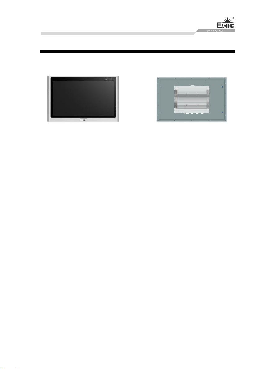
W15 SERIES is a fanless high-performance 15.6″ wide-screen industrial panel PC.
The chassis contains six-generation Intel® Core™ i7/i5/i3 CPUs, and supports
Windows 7(64bit), Windows 10, LINUX(2.6 Kernel) operating systems.
The PC is made of Al-alloy + excellent quality sheet metal. Its system structure
deploys motherboard + expansion board design solution, which features simplicity.
Highly reliable connectors are used among various modular boards, which ensures
highly reliable operating environment. The product has excellent anti-dust,
heat-dissipation and anti-vibration performance.
Targeting high-end MES, integrated monitoring and equipment control and other
fields, W15 SERIES products are mainly used in shield tunneling machines,
production line MES, integrated monitoring (rail transit, building and power plants,
etc.), numerical control machines, single crystal furnace machine, automobile
accessories control, and so on.
W15 SERIES · 1 ·
Page 11
1.2 Specifications
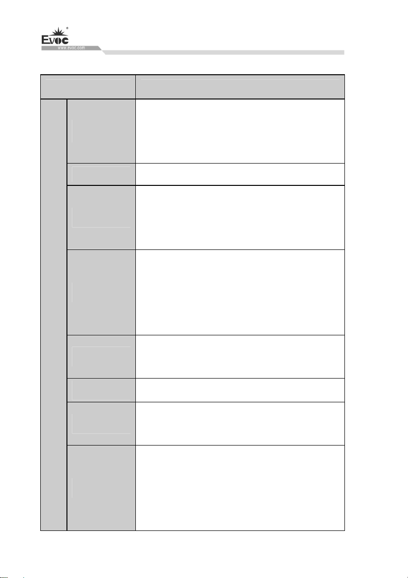
Item Definitions
Product Introduction
Supports Intel® I3-6100TE/6500T/I5-6500TE/I7-6700TE/
Microprocessor
Main Function Indices
Chipset
Memory
Display
Network
Audio
I5-6500 CPU
Note: Refer to the actual configuration for details.
Based on Intel® H110 /C236 platform
Provides two 260Pin DDR4 SO-DIMM memory slots,
which supports up to 16GB. The PC supports up to
32GB memory capacity.
Supports VGA, HDMI display ports
VGA supports a minimum resolution of 640×480
and a maximum resolution of 1920×1080
HDMI maximum resolution: 3840×2160
Supports up to four 10/100/1000Mbps network ports.
LAN1 supports Wake-On-LAN function
HD standard, supporting MIC-IN/LINE-OUT
Storage
Expansion bus
· 2 · W15 SERIES
1 x MSATA interface
3 x SATA interfaces, supporting hotswap function
Provides two Mini PCIe sockets. MPCIe1 can be used
for common Mini PCIe slot card and wireless network
card; MSATA1 can be used for common Mini SATA
interface card and 4G module.
Page 12
Product Introduction
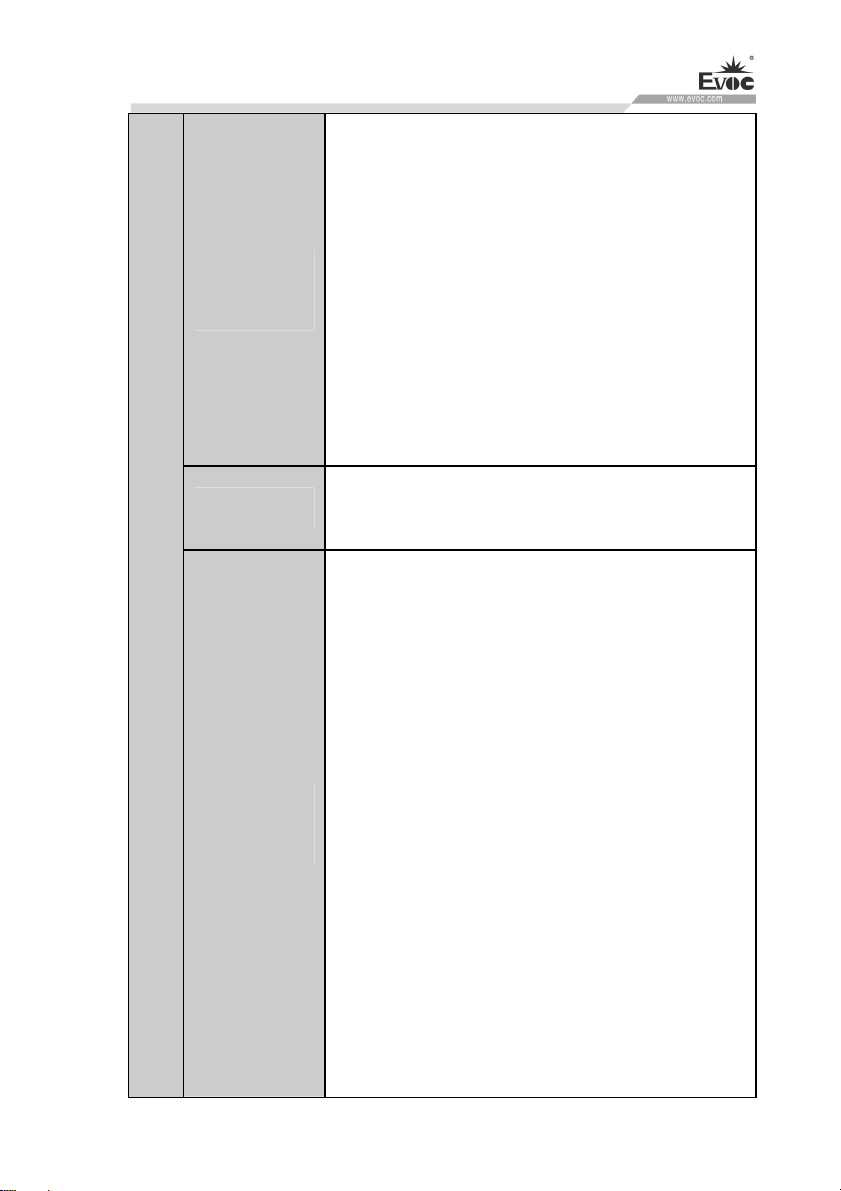
Screen: 15.6″ TFT LCD
Resolution: 1920×1080
Brightness: 250cd/m2
LCD screen
features
Touch screen
External IO
Contrast ratio: 800:1
Viewable angle (CR≥10)
Horizontal: 80°~80°; vertical: -70°~70°
Note: The parameters above are for reference only,
and actual product shall prevail if there is any
difference.
Port type: USB
Type: capacitive type
Up to six COM ports, COM1~COM6 support
RS-232/RS-422/RS-485 mode, RS-232 by default
Up to: four USB3.0 ports + four USB2.0 ports
1 x PS/2 keyboard/mouse port
Up to four 10/100/1000Mbps network ports
1 x VGA port
1 x HDMI port
ports
1 x DVI-D port
1 x AUDIO port (supporting MIC, LINE-IN,
LINE-OUT)
1 x 8-bit GPIO port (using 1×10 Phoenix terminal)
Note: The quantity and type of the above ports
may vary with different configurations. The actual
product shall prevail, if there is any difference.
W15 SERIES · 3 ·
Page 13
Outline
Dimensions
Recommended
Dimensions for
Hole Opening
Product Introduction
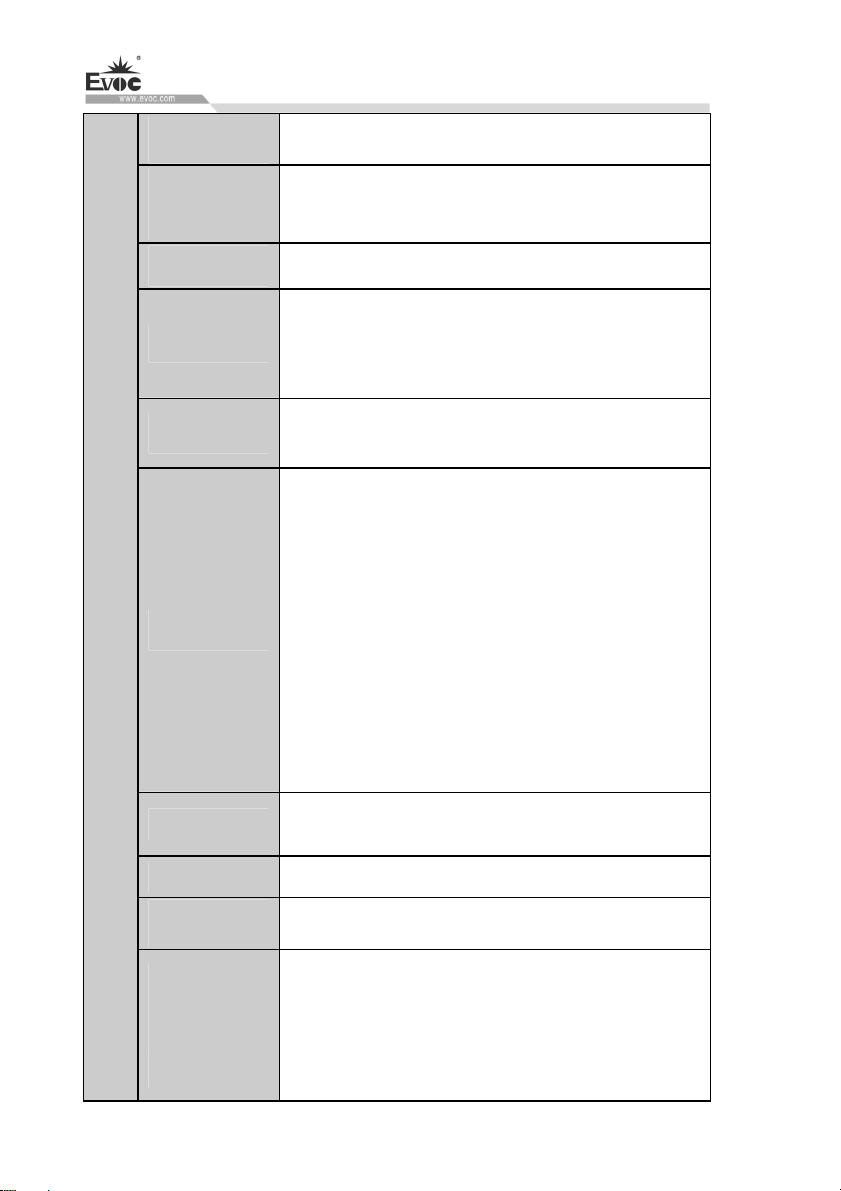
407mm(W) × 259.3mm (H) × 86.4mm(D)
384mm(W) × 236mm(H)
Main Performance Indices
Weight
Temperature
Humidity
EMC
Reliability
About 5.9Kg (excluding the weight of package)
Operating temperature:
Operating with mechanical hard disk: 0℃~45℃
Storage temperature: -30℃~+65℃
Temperature 40℃, relative humidity 95%
(non-condensing)
GB 9254-2008 Radiation disturbance Class (A)
GB 9254-2008 Conduction disturbance Class (A)
GB/T 17626.2.2006 ESD discharge Level (2)
GB/T 17626.4-2008 Pulse group immunity Level
(2)
GB/T 17626.5-2008 Surge (impact) immunity
Level (2)
GB/T 17626.6-2008 Conduction immunity Level
(2)
MTBF≥50000h
MTTR≤0.5h
Safety
Protection
grade
Mechanical
and
environmental
adaptability
· 4 · W15 SERIES
Meets basic requirements of GB4943-2011
Front panel meets IP65
Power-off status anti-vibration: frequency 5-15Hz,
amplitude 1mm; frequency 15-200Hz,
acceleration 1.0g
Impact: 15g g acceleration, 11ms duration
Page 14
Product Introduction
Input voltage/frequency: 220VAC/50Hz (with
Power feature
Power consumption of the PC: 23.35W (standby
1.3 Operating Instructions
1.3.1 External Functions
adapter)
Input voltage/frequency: 9VDC-36VDC (no
adapter, direct input to the PC)
status);Power consumption of the PC: 41.95W
(operating 3D MARK 100%)
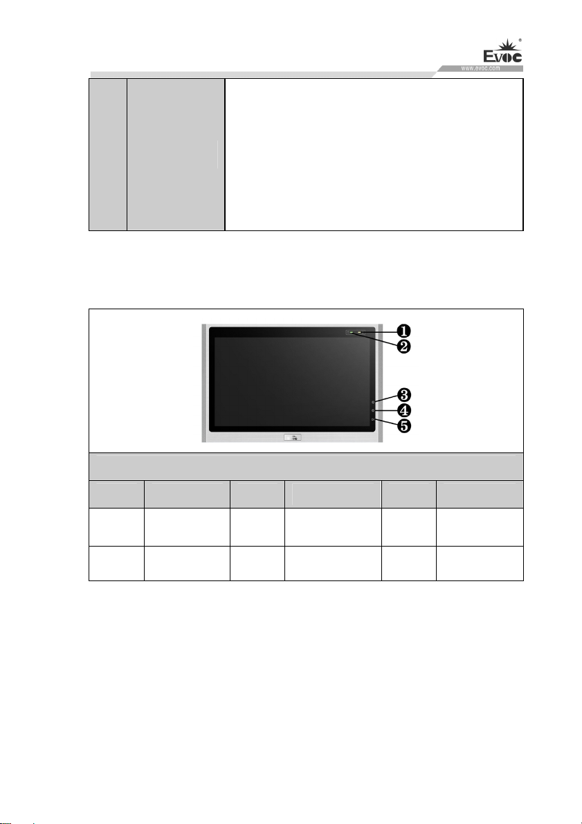
Front View of the PC
Location Description Location Description Location Description
1
4
Note:(1) When the display switch is used to switch on/off the display screen, the
touch screen function will be enabled/disabled. After it is enabled, the touch screen
controller will reestablish communication with the CPU and load the driver. Therefore,
it is suggested that the interval for the screen switch on/off should not be less than 30
seconds, to ensure that the touch screen controller can load the driver correctly and
avoid the touch screen failure.
(2) To adjust the brightness of the display, you need to long press the button to
increase/decrease the brightness, and short/quick clicking is invalid.
Power
indicator
Decrease
luminance
2 HDD indicator 3
5 Display switch
W15 SERIES · 5 ·
Increase
luminance
Page 15
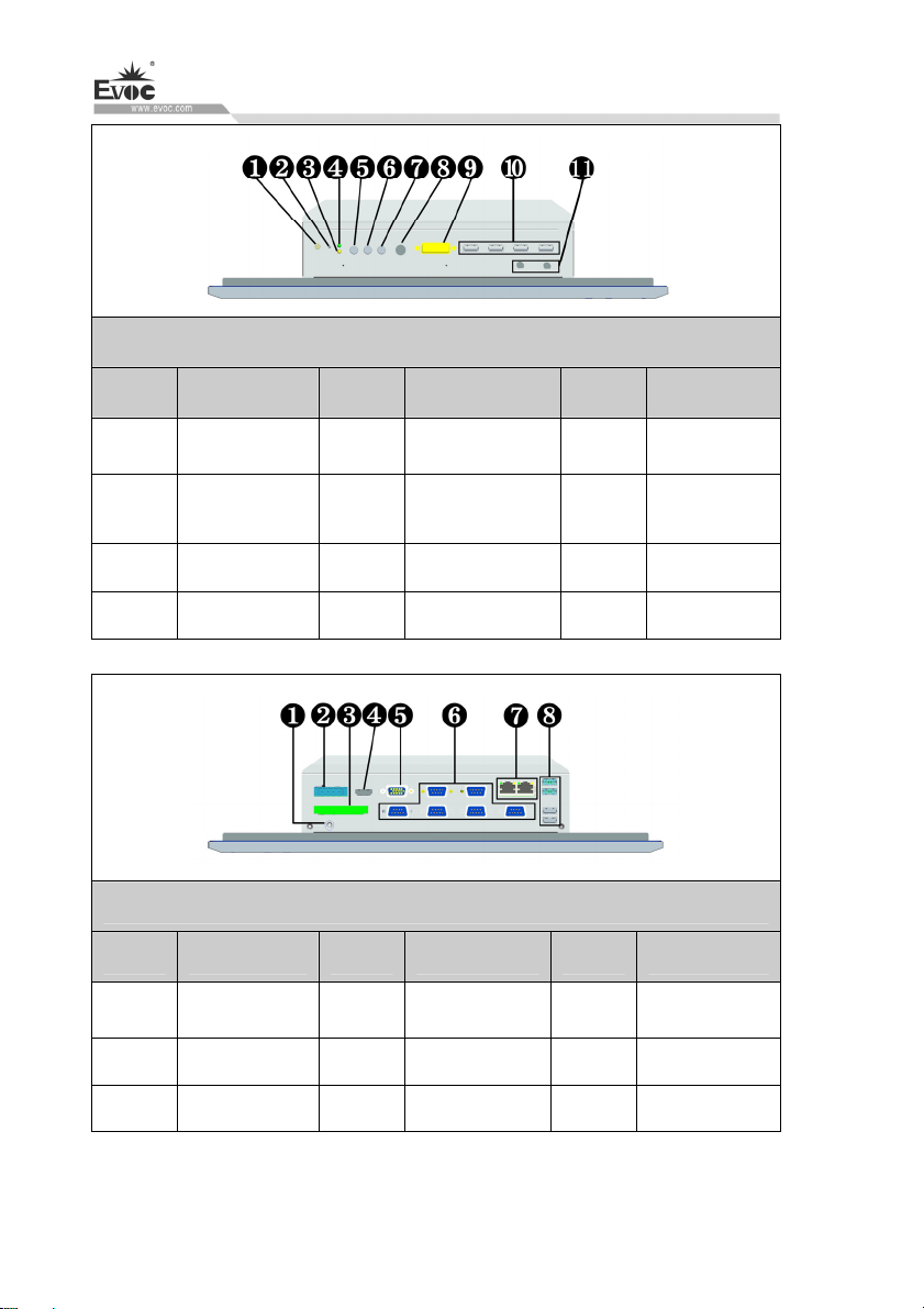
Product Introduction
Diagram of upper IO ports of the PC
Location Description Location Description Location Description
1
4
Switch button
Power
indicator
2
Reset button
3
5 LINE OUT 6 LINE IN
HDD
indicator
7 MIC 8 PS/2 9 DVI
10
USB1~USB4
11 ANT1/2
Diagram of lower IO ports of the PC
Location Description Location Description Location Description
1 Ground screw 2
4 HDMI 5 VGA 6
Power
connector
3 GPIO
COM1~COM6
7 LAN1/2 8
USB5~USB8
Note: For different configurations of the PC (with different motherboards), the
external IO ports may be different, and the actual configuration prevails.
· 6 · W15 SERIES
Page 16
Product Introduction
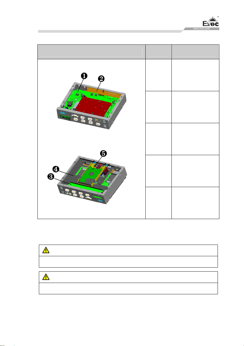
1.3.2 Internal Layout
Internal Layout of the PC Location Description
1 Motherboard
2 Front IO board
3 Rear IO board
Motherboard
4
bracket
1.3.3 Operation Control
Warning
Pressing On/Off button won’t cut off the power of the PC!
Caution
When the PC executes hardware reset, data may be lost.
5 HDD module
W15 SERIES · 7 ·
Page 17
Product Introduction
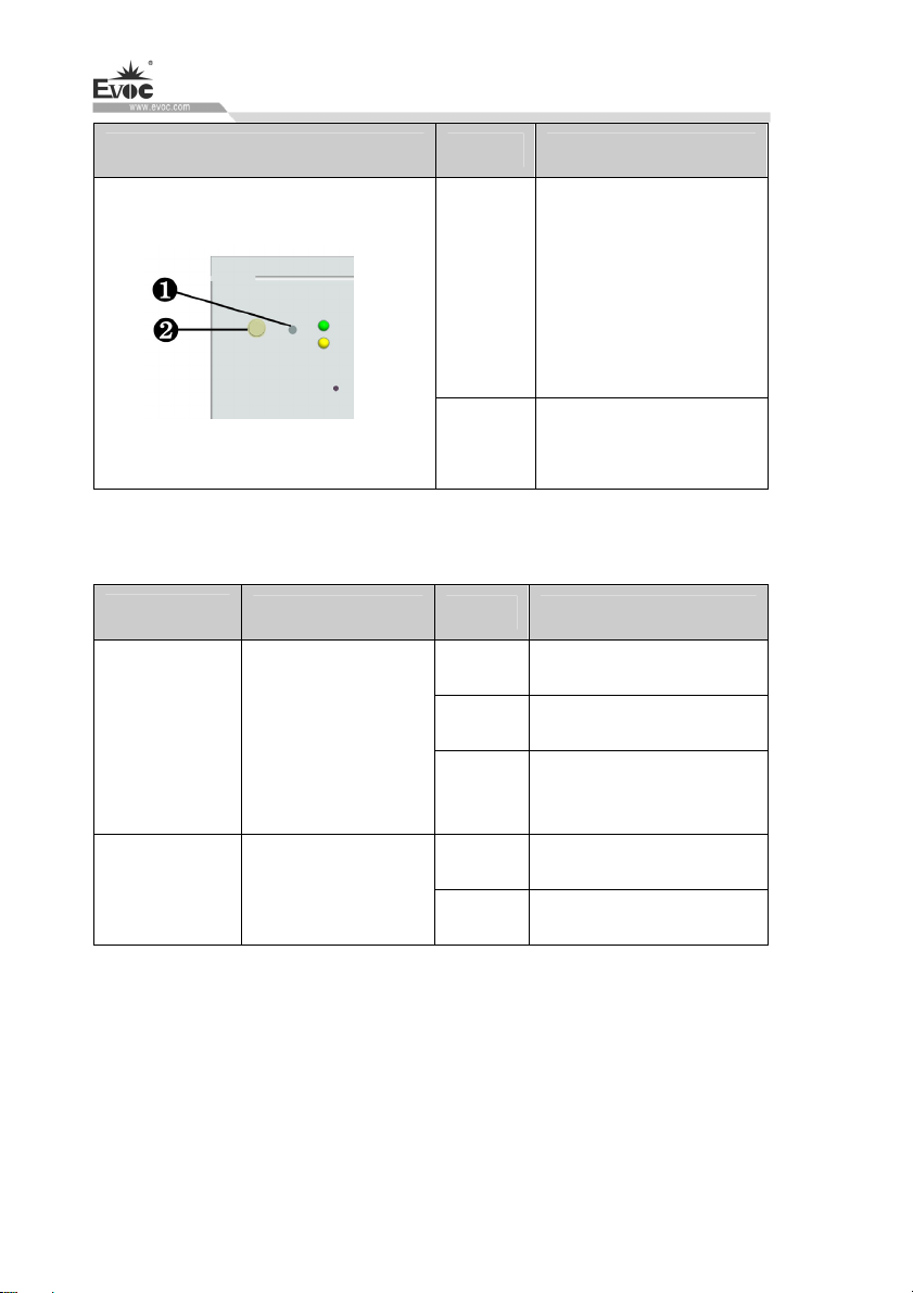
Control Button Location Description
Reset button
A pointed object or a clip
1
can be used to operate the
reset button. Pressing this
button will trigger
hardware reset.
1.4 Status LED
Display
POWER PC status indication
HDD
Meaning LED Description
Indicating access to
hard drive
On/Off button used to
2
switch on/off the PC.
Off Disconnected from power
Green PC is operating
Orange
Off Not being accessed
Yellow Being accessed
Disable LCD screen
backlight and touch screen
· 8 · W15 SERIES
Page 18

Application Scheme
2. Application Scheme
2.1 Transportation
Well-packaged products are suited for transportation by all kinds of vehicles. During
transportation, products should not be put in open cabin or carriage. During
transshipping, products should not be stored in open air without protection from the
atmospheric conditions. Products should not be transported together with inflammable,
explosive and corrosive substances and are not allowed to be exposed to rain, snow
and liquid substances and mechanical force.
2.2 Storage
Products should be stored in package box when it is not used. And warehouse
temperature should be 0°C ~ 40°C, and relative humidity should be 20% ~ 85%. In
the warehouse, there should be no harmful gas, inflammable, explosive products, and
corrosive chemical products, and strong mechanical vibration, shock and strong
magnetic field interference. The package box should be at least 10cm above ground,
and 50cm away from wall, thermal source, window and air inlet.
Caution
Risk of destroying the device!
When shipping the PC in cold weather, please pay attention to the extreme
temperature variation. Under this circumstance, please make sure no water
drop (condensation) is formed on the surface or interior of the device. If
condensation is formed on the device, please wait for over twelve hours before
connecting the device.
W15 SERIES · 9 ·
Page 19
Application Scheme
2.3 Opening the Box and Initial Examination
2.3.1 Opening the Box to Examine the PC
Please pay attention to the following issues when opening the box:
● Do not discard the original packing material. Please keep the original packing
material for re-transportation.
● Please keep the documentation at a safe place. The documentation, which is a part
of the device, is required for initial device debugging.
● When doing the initial examination, please check whether there are distinct
damages to the device caused during the transport.
● Please check whether the delivery contains the intact device and all of the
independently ordered accessories. Please contact the customer service when any
unconformity or transportation damages occur.
2.3.2 Data to Identify the PC
Note
During maintenance or after the product is stolen, this code can be used to identify
the PC. Please do not rip it off.
Serial No.: Located on the chassis body (as shown below)
2.4 External Environment Conditions
When planning a project, the following conditions should be considered:
Please observe the weather and mechanical environment condition specified in
the operating instructions.
· 10 · W15 SERIES
Page 20

Application Scheme
Please avoid extreme environment conditions, and keep the PC away from dust,
moisture and heat.
Please avoid direct sunlight on the PC.
Please make sure other assemblies or the side of cabinet is 50mm and 100mm
respectively away from the upper/lower side of the PC.
Please do not cover the ventilation hole of the PC (If have).
The installation location requirement allowed for the PC should always be
observed.
The I/O connected or installed should not generate reverse voltage of larger than
0.5V in the PC.
W15 SERIES · 11 ·
Page 21
Installing the Product
3. Installing the Product
3.1 Installation Information
Before installing the PC, please read the following installation instructions:
Note
When installing the product in the switch cabinet, please observe the assembly
guidance, related DIN/VDE requirements and specific regulations of the
country/region.
3.2 Mounting Method
□19″ Rack Mount □Desktop ■Embedded Panel
□Wall Mount ■VESA Standard Arm □Portable
□Others___________
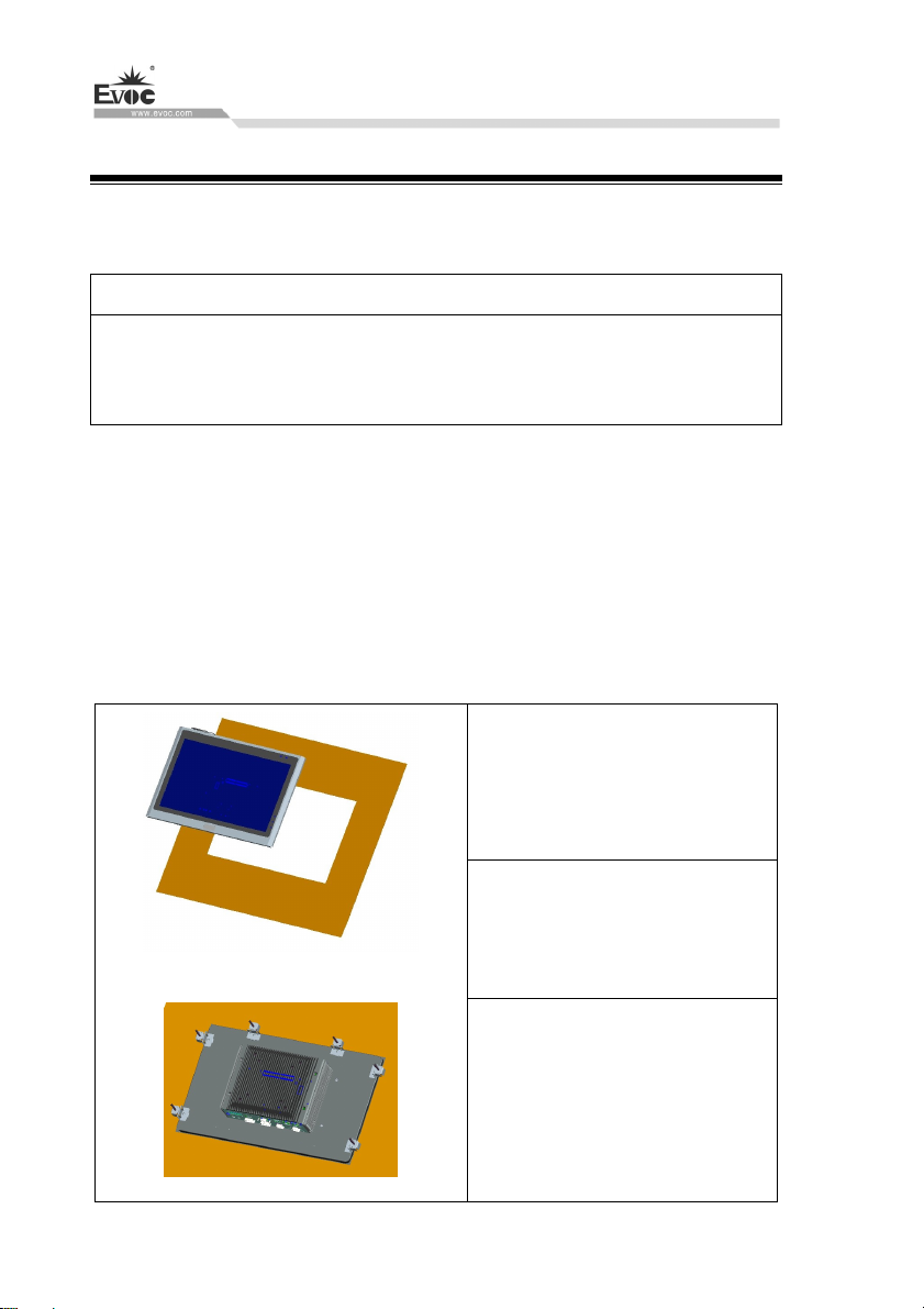
3.2.1 Embedded Panel Installation
· 12 · W15 SERIES
Step 1: Insert the machine vertically
into the already-prepared square
hole panel, as shown in the left
picture.
Note: Screws for installing the
mounting hook are the accessories
enclosed with the product.
Step 2: Hang the hooks on the back
of the machine, then tighten the
long screws, which press firmly
against the panel.
Page 22
Installing the Product
Note: Th
Material Square hole Mounting
requirements are as the
following table
e installation
Metal sheet type (minimum
thickness: 1.5mm)
Warning
Make sure the wall or the ceiling or the carrier can bear the load four times as
heavy as the total weight of the PC (including the cabinet rack and additional
expansion modules).
384mm×236mm
Tighten from the rear with the
hook (accessories)
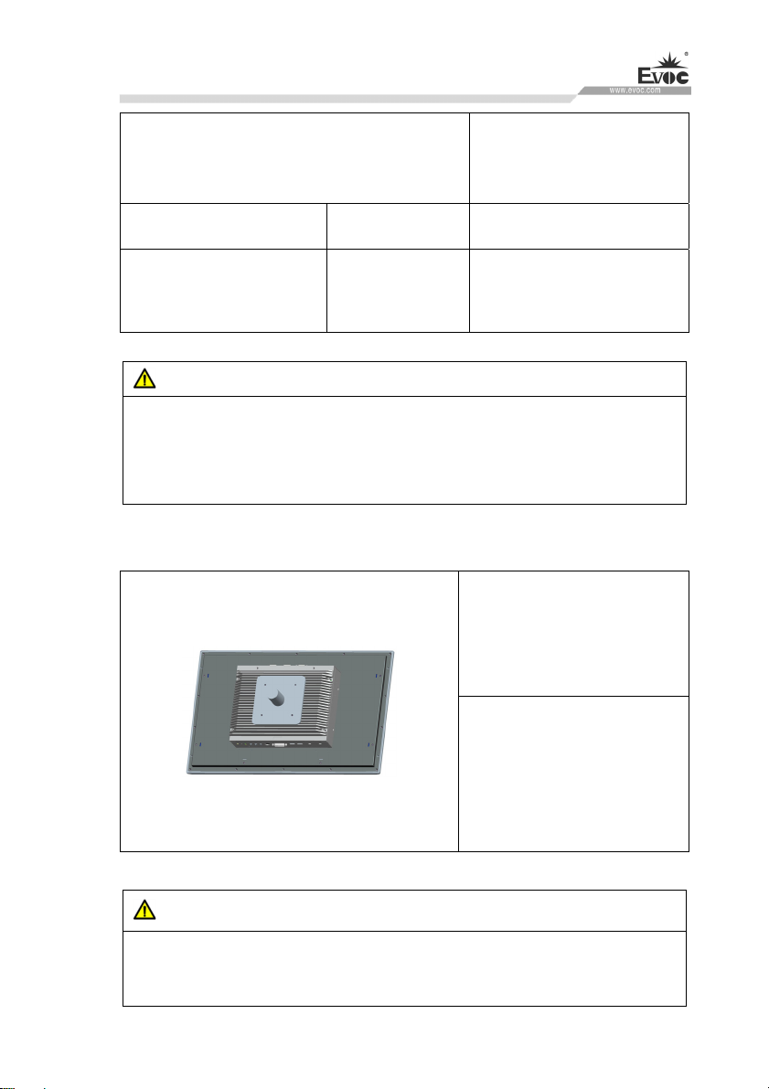
3.2.2 VESA Standard Supporting Arm Installation
Step: Use screws to fasten the
PC onto the supporting arm, as
shown in the left picture.
Note: During the installation,
use the screws that come with
the PC or select screws
according to the user manual.
Warning
The weight bearing capacity of VESA supporting arm should be at least twice the
weight of the PC.
W15 SERIES · 13 ·
Page 23
PC Connection
4. PC Connection
4.1 Things to Know before Connection
Warning
The connected or built-in peripherals with opposite polarities are not allowed.
Warning
The device only operates when connecting with grounded power. No operation is
allowed when the device power is ungrounded or only impedance is grounded.
Warning
Rated voltage of the device in use shall be in accord with power feature of the
product.
Note:
Only the peripheral devices approved for industrial application can be used. When
operating the PC, hot swappable IO modules (USB) can be used. The IO devices
without hot swap function can only be connected when the PC is powered off.
4.2 Product Grounding
Low impedance ground connection is more helpful to release the interference
produced by the external cables, the signal cables or the cables connecting the IO
module to the grounding system
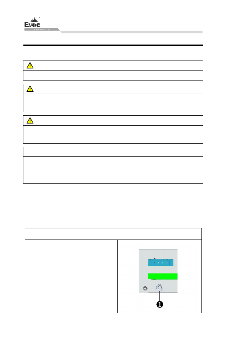
Ground Terminals
The ground terminal (large surface ①
and large area contact) shall be connected
with the cabinet installed with the PC or
the central grounding busbar on the
device. The minimum cross section area
of the cable shall be no less than 2.5mm
and the grounding resistance shall be no
more than 0.1Ω.
· 14 · W15 SERIES
2
,
Page 24
PC Connection
4.3 Connecting the Device to Power
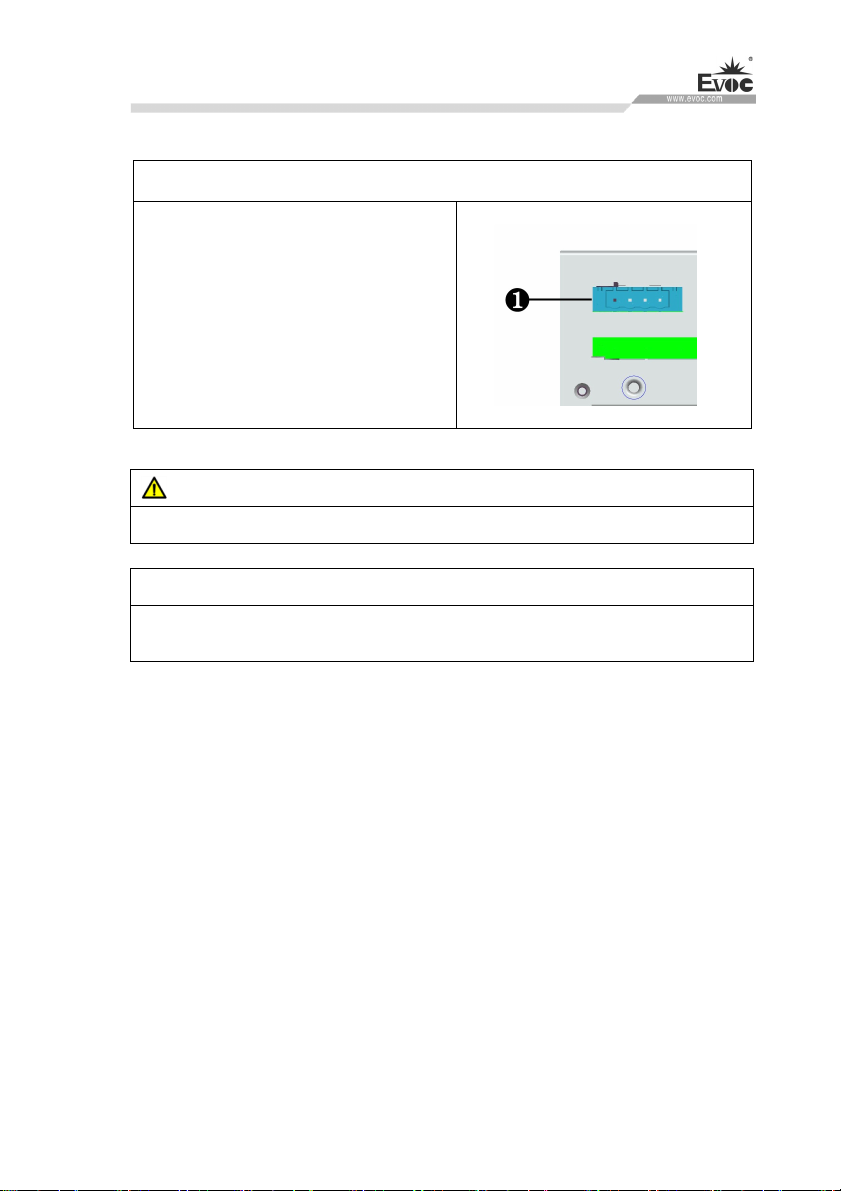
Steps to connect the device to power
Insert the terminal block on the adpater in
the accessories into the connector ①
shown in the picture.
Danger
Disconnect the power source and data cable during a lightning storm.
Attention
The PC is completely isolated from the power supply only by disconnecting the
power connector.
W15 SERIES · 15 ·
Page 25
Debugging
5. Debugging
5.1 Operating System
Supported operating system: Windows 7(64bit), Windows 10, LINUX(2.6
Kernel)
5.2 Port Definition
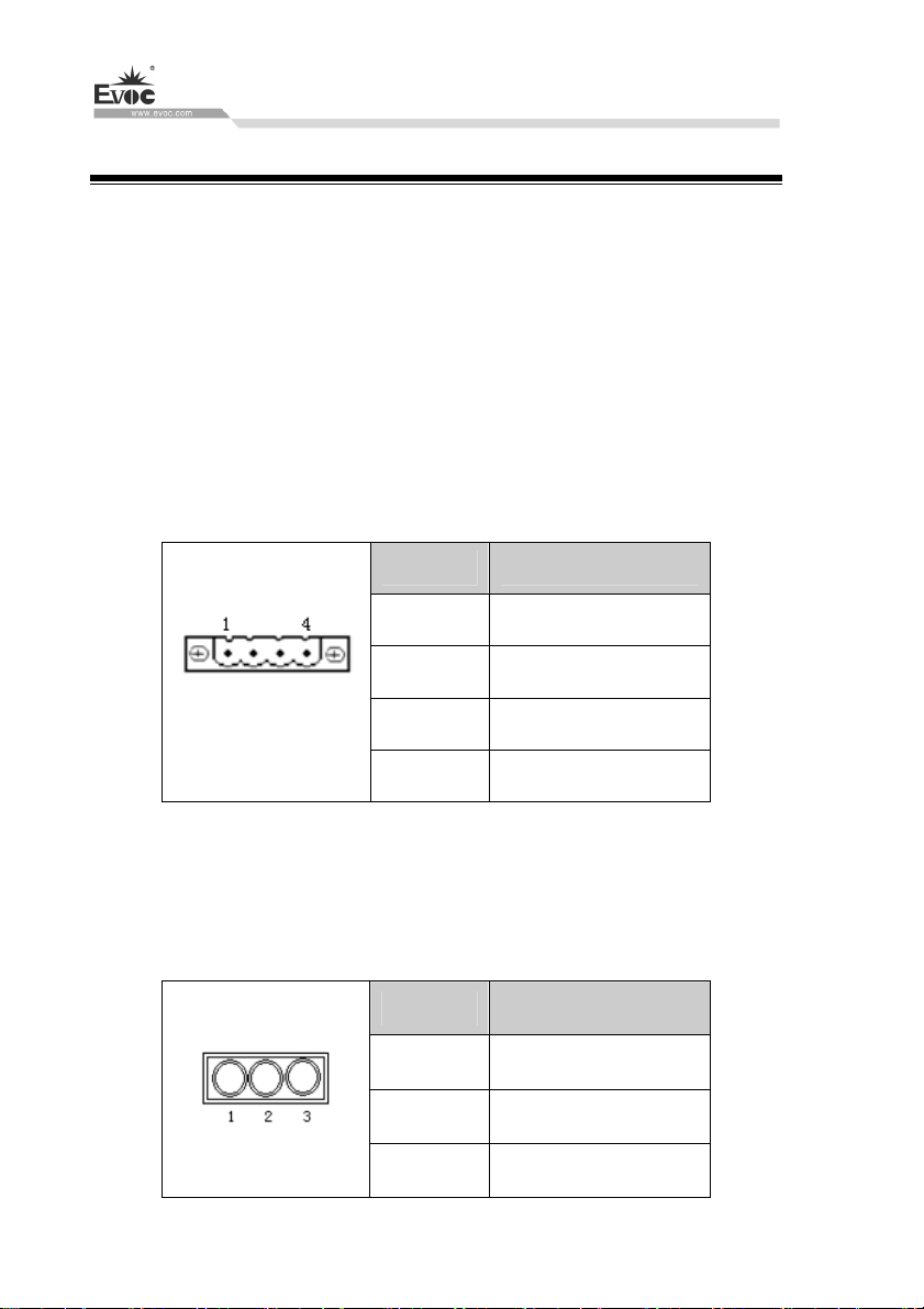
5.2.1 DC Power Input Connector
It provides one 4P horizontal-type Phoenix terminal socket, which supports single
power input and a voltage input range of 9-36 VDC. Its pin definition is as follows:
Pin Signal Name
1 Positive
2 Negative
DC IN 9V-36V
3 SW-
4 SW+
Note: SW+, SW-: remote switch-on/off input signal, to trigger switch-on/off of
SW+ and SW- under ATX mode.
5.2.2 AUDIO Port
Pin Signal Name
1 MIC
· 16 · W15 SERIES
2 LINE IN
3 LINE OUT
Page 26
Debugging
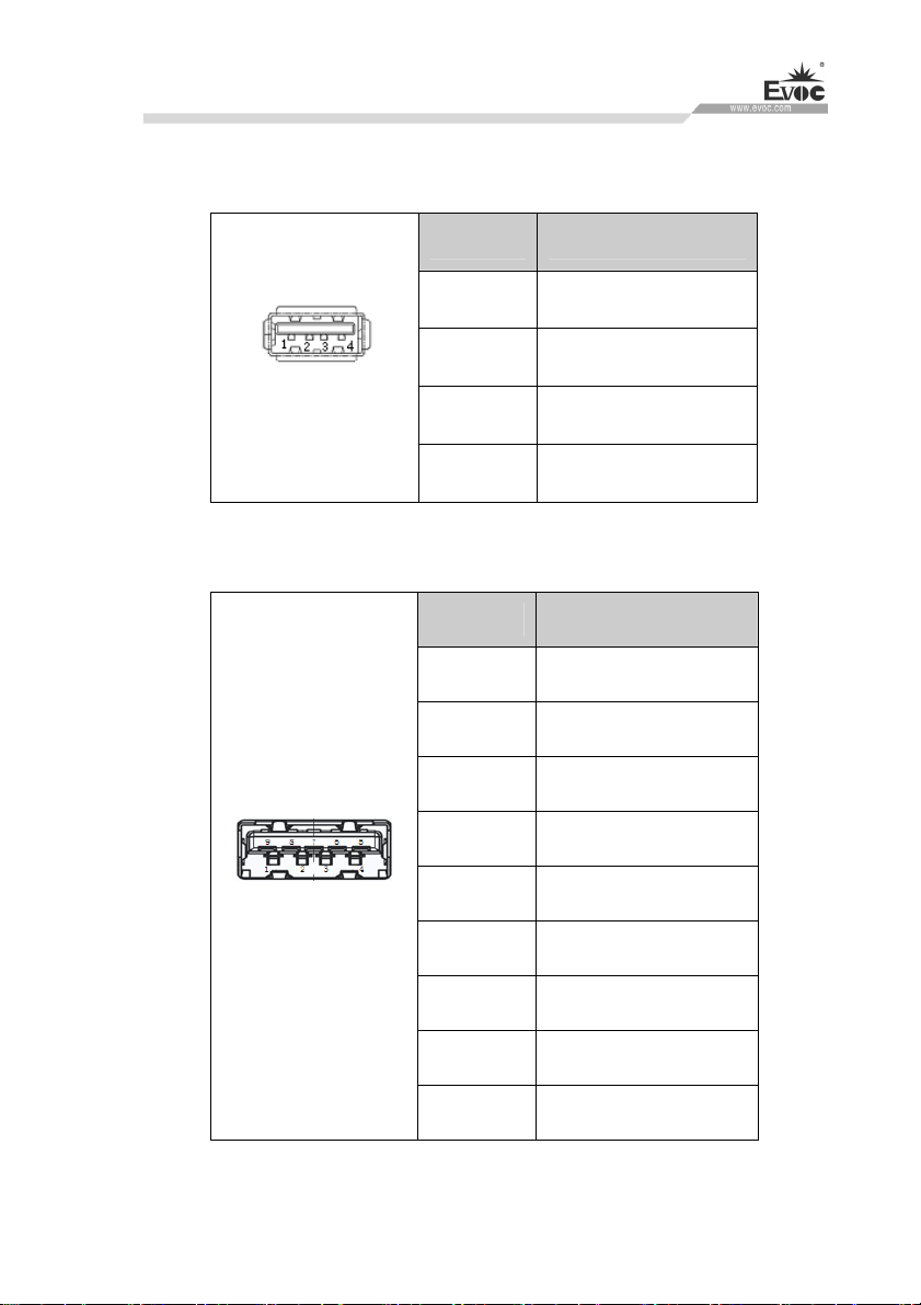
5.2.3 USB Port
1.USB2.0 standard port
Pin Signal Name
1 +5V_USB
USB1~USB4
2.USB3.0 standard port
USB5~USB8
2 USB_DATA-
3 USB_DATA+
4 GND
Pin Signal Name
1 +5V_USB
2 USB_DATA-
3 USB_DATA+
4 GND
5 USB_SSRX-
6 USB_SSRX+
7 GND
8 USB_SSTX-
9 USB_SSTX+
W15 SERIES · 17 ·
Page 27
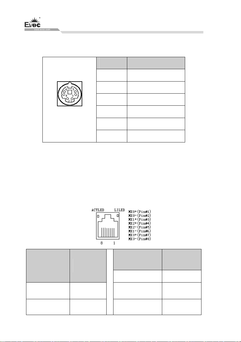
5.2.4 PS/2 Keyboard/Mouse Port
It provides one PS/2 keyboard/mouse port.
Pin Signal Name
Debugging
1 KB_DATA
2 MS_DATA
MS/KB
3 GND
4 +5V
5 KB_CLK
6 MS_CLK
5.2.5 Network Port
It provides up to four 10/100/1000Mbps Ethernet ports, standard RJ45 connectors.
LILED and ACTLED are the LEDs on both sides of the Ethernet port, which
respectively indicates the activity status and the speed of LAN. Please refer to the
status description for each LED:
ACTLED
(single color:
green LED)
Network
activity
LILED
(dual-color:
orange and green)
Green 1000Mbps
Network speed
Flash
Off
· 18 · W15 SERIES
Data being
transmitted
No data being
transmitted
Orange 100Mbps
Off 10Mbps
Page 28
Debugging
Note: No matter the 1000Mbps LAN port has or
the left side means there is no data being transmitted. If there is data being transmitted,
the green LED on the left side should be at “Flashing” status. If the network is
connected but no data being received or transmitted, the green LED should be at
“Off” status; When there is broadcast packet, it is normal if ACTLED is “Flashing”.
has no Link signal, the ACTLED on
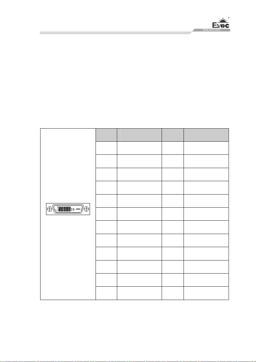
5.2.6 DVI Port
It provides one standard DVI-D port (brought out by DVI-I vertical connector). Its pin
definition is as follows:
Pin Signal Name Pin Signal Name
1 DATA2- 13 NC
2 DATA2+ 14 +5V
3 GND_DVI 15 GND
4 NC 16 HOTPLUG
5 NC 17 DATA0-
6 DDCCLK 18 DATA0+
DVI-D
7 DDCDATA 19 GND_DVI
8 NC 20 NC
9 DATA1- 21 NC
10 DATA1+ 22 GND_DVI
11 GND_DVI 23 CLK+
12 NC 24 CLK-
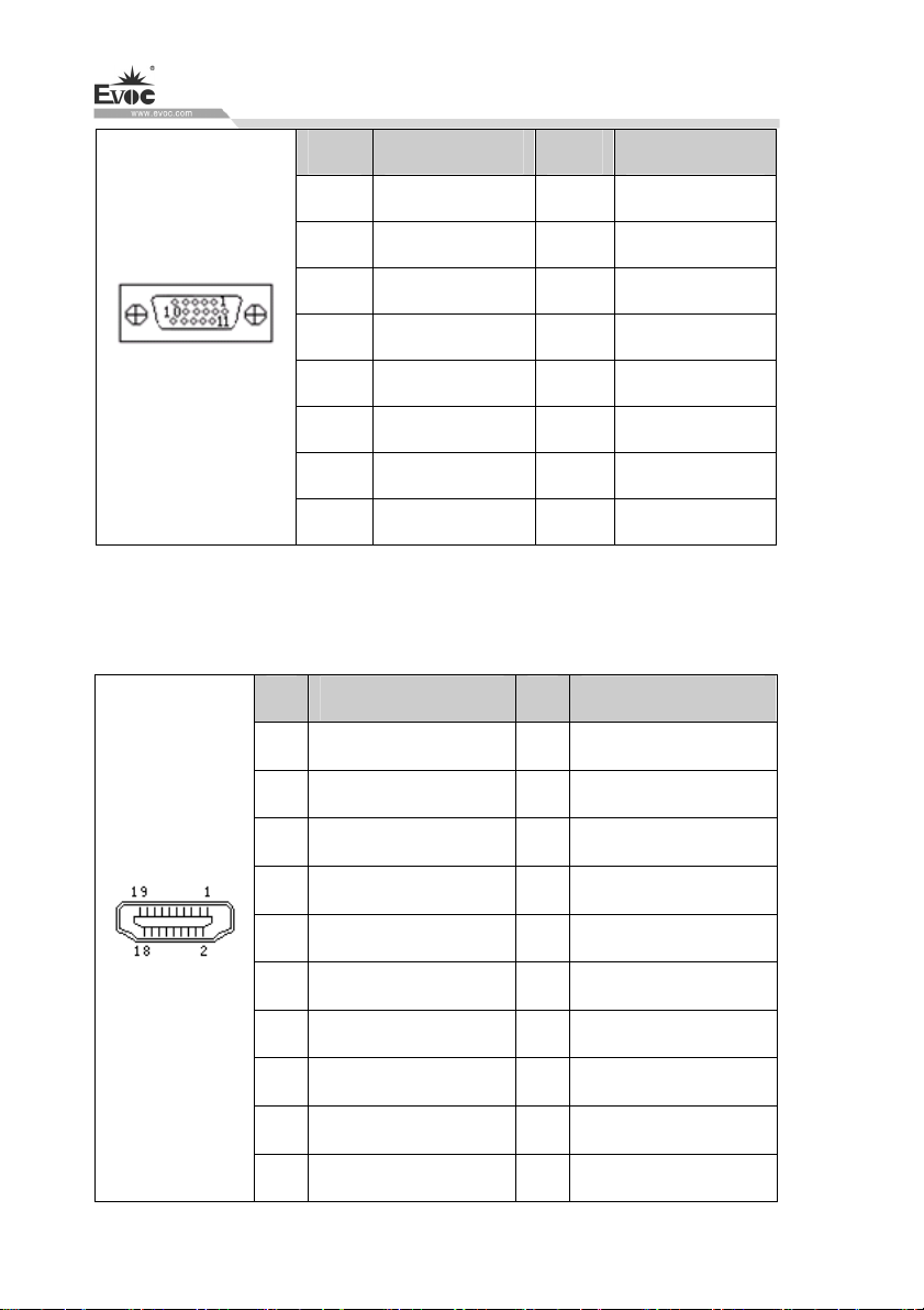
5.2.7 VGA Port
It provides one standard DB15 VGA port. Its pin definition is as follows:
W15 SERIES · 19 ·
Page 29
Debugging
Pin Signal Name Pin Signal Name
1 Red 2 Green
3 Blue 4 NC
5 GND 6 GND
7 GND 8 GND
VGA
9 NC 10 GND
11 NC 12 DDCDATA
13 HSYNC 14 VSYNC
15 DDCCLK
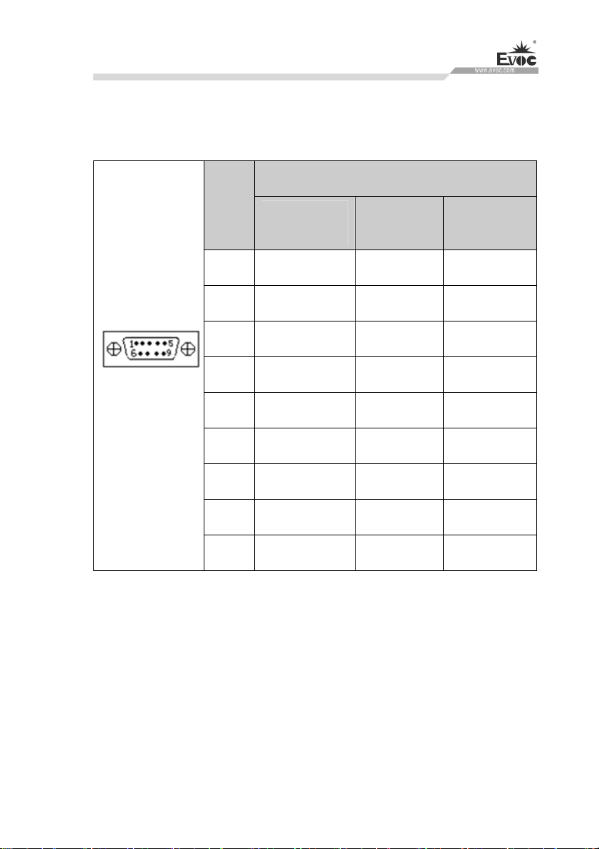
5.2.8 HDMI Port
It provides one 19-Pin Type A HDMI port.
Pin Signal Name Pin Signal Name
1 TMDS DATA2+ 2 TMDS DATA2 Shield
3 TMDS DATA2- 4 TMDS DATA1+
5 TMDS DATA1 Shield 6 TMDS DATA1-
7 TMDS DATA0+ 8 TMDS DATA0 Shield
9 TMDS DATA0- 10 TMDS CLK+
HDMI
11 TMDS CLK Shield 12 TMDS CLK-
· 20 · W15 SERIES
13 CEC 14 RSVD(NC on device)
15 SCL 16 SDA
17 DDC/CEC Ground 18 +5V
19 Hot Plug Detect - -
Page 30
Debugging
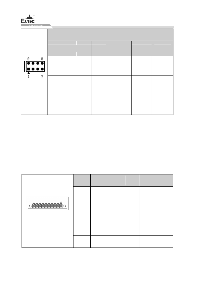
5.2.9 COM Port
It provides up to six COM ports. COM1~COM6 support RS-232/RS-422/RS-485
mode, RS-232 by default. Their pin definitions are as follows:
Signal Name
Pin
1 DCD# TXN DATA-
2 RXD TXP DATA+
3 TXD RXP NC
4 DTR# RXN NC
COM1~COM6
Note: Under RS-485 mode, data receive/send direction is controlled by RTS.
5 GND GND GND
6 DSR# NC NC
7 RTS# NC NC
8 CTS# NC NC
9 RI# NC NC
RS-232
(Default)
RS-422 RS-485
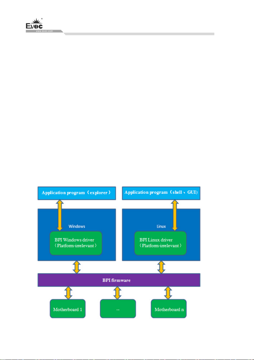
COM mode configuration:
It can be selected via jumper on the I/O board, and please refer to the above table for
its pin definition.The detailed configuration is as follows:
W15 SERIES · 21 ·
Page 31
Debugging
Pin Setup Mode Selection
COM3 COM4 COM5 COM6
JP1 JP4 JP7 JP10 1-2 3-4 5-6,7-8
RS-232
(Default)
RS-422 RS-485
JP1~JP12
Note: 1. Mode selection for COM1,COM2 is carried out under BIOS. (For details ,
please refer to Page 37, 38)
2. If COM1~COM6 are to be set to automatic flow control function of RS-485 mode,
it needs to be set under BIOS. (For details , please refer to Page 37, 38)
JP2 JP5 JP8 JP11 1-3,2-4 3-5,4-6 3-5,4-6
JP3 JP6 JP9 JP12 1-3,2-4 3-5,4-6 3-5,4-6
5.2.10 GPIO Port
Pin Signal Name Pin Signal Name
1 D1 2 D2
3 D3 4 D4
GPIO
(pitch: 3.81mm)
Note: The factory default status is high level(5V),and the voltage range of
input/output signal is 0-5V.
· 22 · W15 SERIES
5 D5 6 D6
7 D7 8 D8
9 GND
10 VCC
Page 32

Software Introduction
6. Software Introduction
Software
Name
BPI
eManager
BIOS programming interface
specification, which provides
unified interface for software
to access hardware.
A platform management
application software
developed based on BPI,
which enables users to check
the status of embedded PCs,
keep daily records, and
facilitates basic functions of
embedded PCs, such as WDT,
GPIO, boot order, and etc.
Description Supported Range
All supporting BPI motherboards
and PCs of EVOC company
All the motherboards/complete
PCs that support BPI can run
eManager, and the sub-functions
depend on the specific
motherboard. For those which do
not support BPI, customization
service can be provided. (Please
consult customer service for the
cost).
W15 SERIES · 23 ·
Page 33
Software Introduction
6.1 BPI Overview
BPI (BIOS Programming Interface) is a cross-platform, easy-to-maintain software
interface specification, which supports access to hardware under the Protected Mode
of 32-bit or 64-bit operating system and supports multi-process and multi-threading
hardware access. BPI is a bridge between hardware and application software, and its
purpose is to provide a unified standard interface for the application layer (in the form
of library function, similar to library function of standard C). With BPI, application
software engineer do not need to care about the specific hardware solution of the
motherboard. The users can use BPI library to rapidly develop their own software
products, and when the hardware of the motherboard is upgraded, there is no need to
modify the application software or driver and the former software can operate on the
new platform normally. BPI has greatly sped up the product development and reduced
the maintenance cost. The BPI architecture is shown in the Figure 1 below:
· 24 · W15 SERIES
Figure 1 BPI architecture
Page 34

Software Introduction
1. Function Supported by BPI
1) Watchdog
Supports Watchdog boot, stop and feed Watchdog function.
2) GPIO
Supports GPIO input/output programming.
3) Hardware monitoring
Supports monitoring of motherboard CPU temperature, system temperature, fan
rotation speed and motherboard core voltage detection, such as CPU Core
voltage, V12.0, battery voltage, and etc.
The user can use BPI library for second development based on application
requirement, for example:
a) Detecting CPU temperature: If the temperature is too high, a buzzer will
be triggered to send alarm.
b) To control peripheral devices by GPIO programming.
2. Advantages of BPI
1) Platform Irrelevant
It is an interface provided by BPI to application layer, which means the BPI
library function is platform-irrelevant, so the software developed by BPI
function library can operate on a new hardware platform supporting BPI
function normally without making any modification.
2) Security and High Reliability
The BPI function library accessing the hardware is programmed by the
motherboard developer and is strictly tested; therefore, it can avoid system
malfunction caused by improper operation of the system hardware.
W15 SERIES · 25 ·
Page 35

Software Introduction
3) Easy Maintenance
Traditional WDT and GPIO programming are closely related to the hardware
with complicated test and debug process and software of different platforms;
however, the software developed by BPI only requires one set of the
maintenance software.
4) Low Cost
Developing the applications by BPI will not result in additional hardware and
software cost. Application software engineer can conveniently use BPI library
functions for second development, and do not need to pay attention to access
information of specific hardware. So it will greatly reduce the development
difficulty, shorten development cycle and boost time-to-market for the system
integrator.
6.2 FMI Overview
FMI (Firmware Management Interface) is management software developed based on
BPI specifications. FMI supports eLogo function. For its test program, please refer to
the eManager software in the user manual CD.
1) eLog
eLog keeps operation records of the PC in details, such as the time for first boot,
completion time of the test, date of production, time of each power-on/off, total
times of power-on of the system, times of illegal power-off, total online time
length of the PC, total heart beat times of the CPU. eLog management
information can provide valuable reference for failure analysis and product
upgrade.
BPI library address: please see “Software\Chinese\BPI”
Or “Software\English\BPI” in the enclosed CD
· 26 · W15 SERIES
Page 36

Software Introduction
BPI Library Function Operating Manual
After installing “BPI X Setup.exe”, a BPI Library Function Operating Manual will be
automatically generated, and the operation instructions can be found in
“Start”→“Program”→“EVOC”
→“evoc_bpi_x”.
6.3 eManager Software
eManager software is a device management platform software developed by EVOC.
eManager software can be used for system operation abnormality monitoring, setup of
GPIO input/output mode and electrical level, real-time monitoring of temperature, fan
and voltage status. Among other functions, the eManager software can predict HDD
life.helping users to use and manage the device effectively. The software has the
following functions:
Watchdog (WDT)
GPIO
Hardware detection
Record switch on/off time and draw time data curves
HDD SMART information
6.3.1 Operating Environment
Take Windows operating system as an example, if customer needs library function
provided by BPI, self-developed application program, it only needs to include
EVOC_BPI_DLL.dll, BPI32.sys and BPI64.sys. If the customer needs to operate,
eManager software, directly unzip BPI3.0 installation packet we provided for
installation and boot it up. (Operation of win7 and above operating system needs
administrator authority).
W15 SERIES · 27 ·
Page 37
Software Introduction
6.3.2 Function
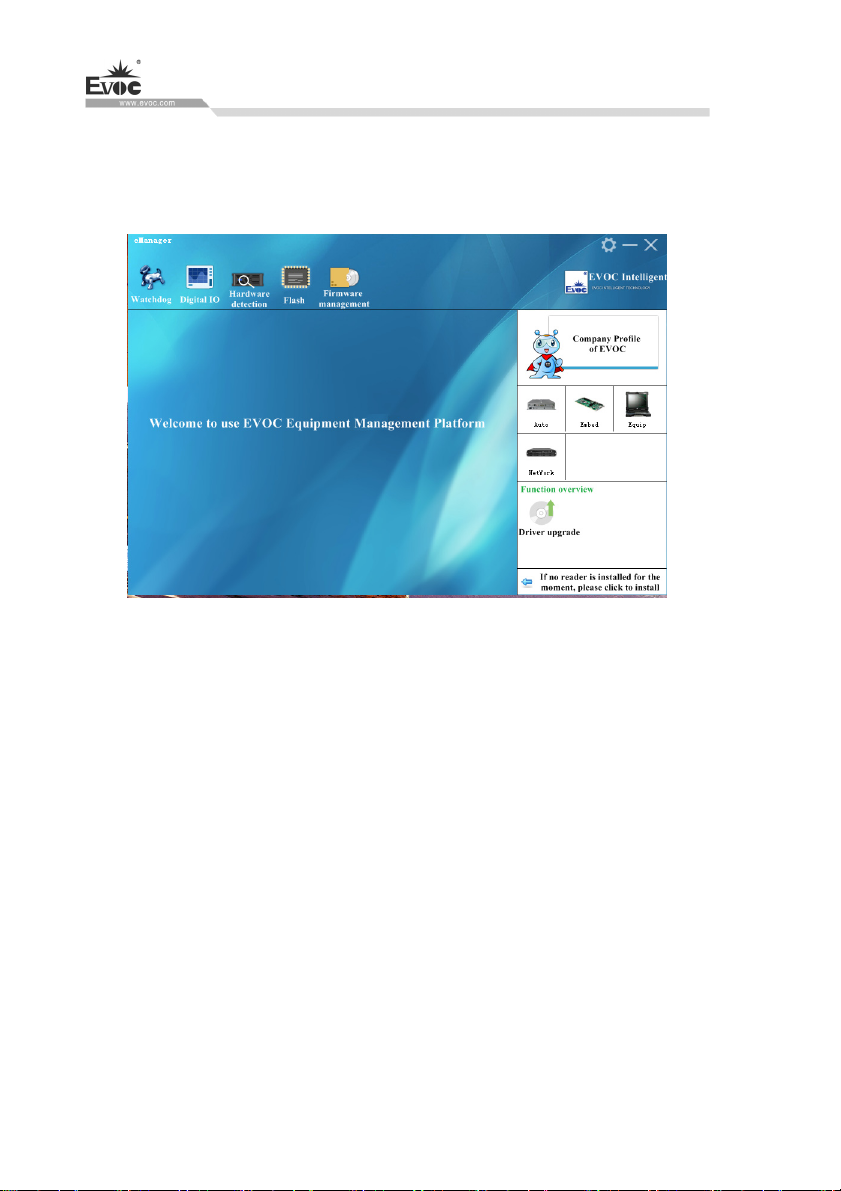
1.Welcome Interface
After the software is opened, the following welcome interface will appear:
2.Watchdog (WDT)
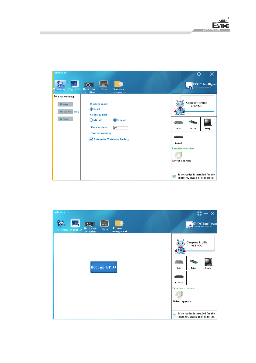
The effect of Watchdog is shown in the picture below.
Using method: First carry out setup. The mode is reset mode; counting unit can be
minute or second; timeout can be any figure within 1-255. After the setup is finished,
press “Start” button on the left, and Watchdog starts counting down. “Current time”
shows the current time for counting-down. Counting-down in reset mode means the
PC reboots at 0. During counting-down, “Feed Watchdog” button can be pressed to
restart counting-down from the set timeout time. Press “Stop” button to stop
Watchdog. Exiting the program when Watchdog is counting down will also stop
Watchdog. If “Automatically feed watchdog” option is selected, when the counted
time is less than 3 seconds, Watchdog will be automatically fed.
Function: Monitors whether the system can be normally operated, and carry out reset
· 28 · W15 SERIES
Page 38
Software Introduction
for abnormality. When abnormality occurs to th
automatically. After counting-down is finished, the system will restart, and recover
from system error.
e system, Watchdog cannot be fed
3.GPIO
W15 SERIES · 29 ·
Page 39
Software Introduction
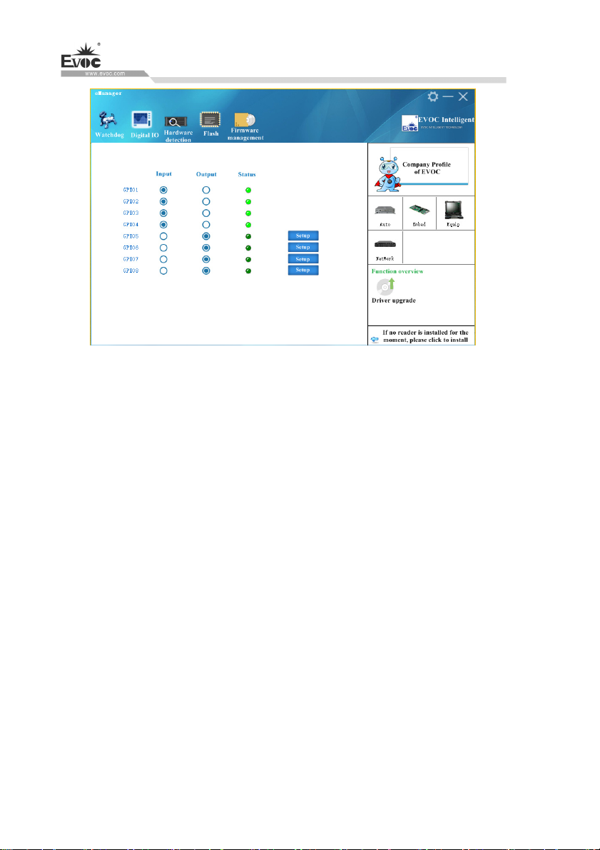
The effect of GPIO is shown in the above picture.
Using method: GPIO is not enabled by default, to avoid the conflict if there is also
GPIO setup in the user program. GPIO supports up to 64Pin display. When it is more
than 8Pin, there will be scroll bar on the interface. GPIO input/output mode can be set
up in the corresponding single option box. The electrical level is indicated by green
LED: On means high level; Off means low level. When GPIO is output mode, the
electrical level status can be switched by corresponding “Setup” button on the right. If
it is a network-type motherboard, the special LED of the motherboard will also be
displayed and can be set up.
Function: Setup of GPIO and Network LED
· 30 · W15 SERIES
Page 40
Software Introduction
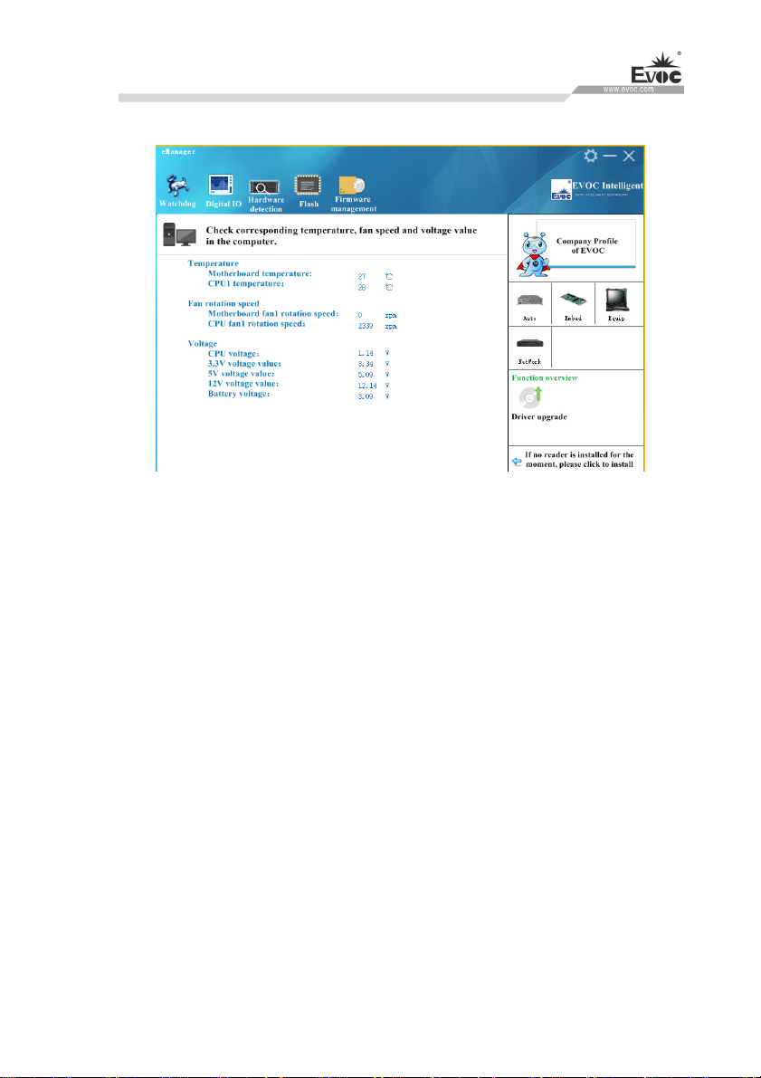
4. Hardware Detection
The effect of hardware detection is shown in the figure above.
Method: After the software switches to hardware detection interface, it will
automatically acquire temperature, fan speed, voltage and other information,
refreshing at a 2S interval.
Function: real-time acquisition of hardware operating status.
W15 SERIES · 31 ·
Page 41
Software Introduction
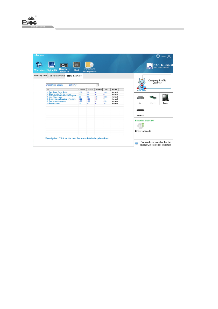
6.3.3 Firmware Management
1. HDD SMART
The effect of boot device is shown in the picture above.
Using method: The boot device order can be changed in the dropdown list in the right
picture, then click “Update” to make it effective. In the next boot, enter into the
system by the set boot order.
Function: To change boot device order under the operating system.
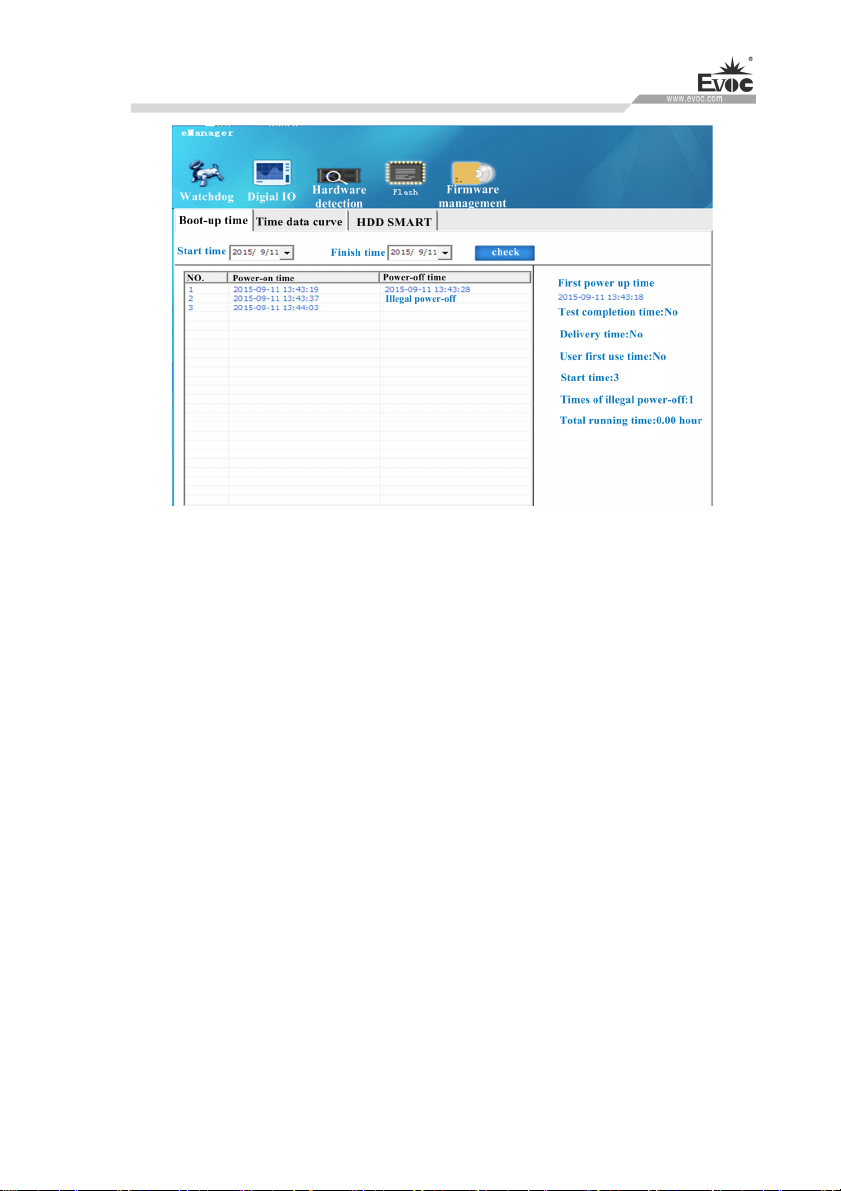
2.Boot-up time
· 32 · W15 SERIES
Page 42
Software Introduction
Boot-up time effect is shown in the above picture
Using method: Select start time and finish time to be checked, check them, and the
listbox will single out the record for times of power-on/off within a specified time
span. The times of illegal power-off and total operation time of the PC can also be
displayed.
Function: To monitor operating status of the PC. To keep record for times of illegal
power-off
3. User Programming
The user can directly use eManager software for management of the device. If users
intend to program software by themselves. Please refer to the complete routine of VB,
VC, C++Builder, Delphi and BPI Programming Interface Operation Manual in the
enclosed CD.
W15 SERIES · 33 ·
Page 43

BIOS Setup
7. BIOS Setup
7.1 UEFI Overview
UEFI (Unified Extensible Firmware Interface) is the latest computer firmware to
replace traditional BIOS. UEFI is solidified in the flash memory on the CPU board. Its
main functions include: initialize system hardware, set the operating status of the
system components, adjust the operating parameters of the system components,
diagnose the functions of the system components and report failures, provide hardware
operating and controlling interface for the upper level software system, guide
operating system and so on. UEFI provides users with a human-computer interface in
menu style to facilitate the configuration of system parameters for users, control power
management mode and adjust the resource distribution of system device, etc.
Setting the parameters of the UEFI correctly could enable the system operating stably
and reliably; it could also improve the overall performance of the system at the same
time. Inadequate even incorrect UEFI parameter setting will decrease the system
operating capability and make the system operating unstably even unable to operate
normally.
7.2 UEFI Parameter Setup
Prompt message for UEFI setting may appear once powering on the system. At that
time (invalid at other time), press the key specified in the prompt message (usually
<Del> or < ESC >) to enter UEFI setting.
All the setup values modified by UEFI (excluding data and time) are saved in the flash
storage in system; the contents will not be lost even if powered down or remove the
battery of the board. The data and time are saved in CMOS storage, which is powered
by battery; unless clearing CMOS is executed, its contents would not be lost even if
powered off.
Note! UEFI setting will influence the computer performance directly. Setting
parameter improperly will cause damage to the computer; it may even be unable to
power on. Please use the internal default value of UEFI to restore the system.
Our company is constantly researching and updating UEFI, its setup interface may
be a bit different. The figure below is for reference only; it may be different from
your UEFI setting in use.
· 34 · W15 SERIES
Page 44
BIOS Setup
7.3 Basic Function Setting for UEFI
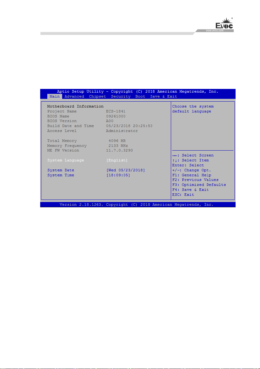
After starting SETUP program, the main interface of Aptio Setup Utility – Copyright
(C) 2018 American Megatrends, Inc. will appear:
Main
System Date
Choose this option and set the current date by < + > / < - >, which is displayed
in format of month/date/year. Reasonable range for each option is: Month (1-12),
Date (01-31), Year (Maximum to 2099), Week (Mon. ~ Sun.).
System Time
Choose this option and set the current time by < + > / < - >, which is displayed
in format of hour/minute/second. Reasonable range for each option is: Hour
(00-23), Minute (00-59), Second (00-59).
W15 SERIES · 35 ·
Page 45
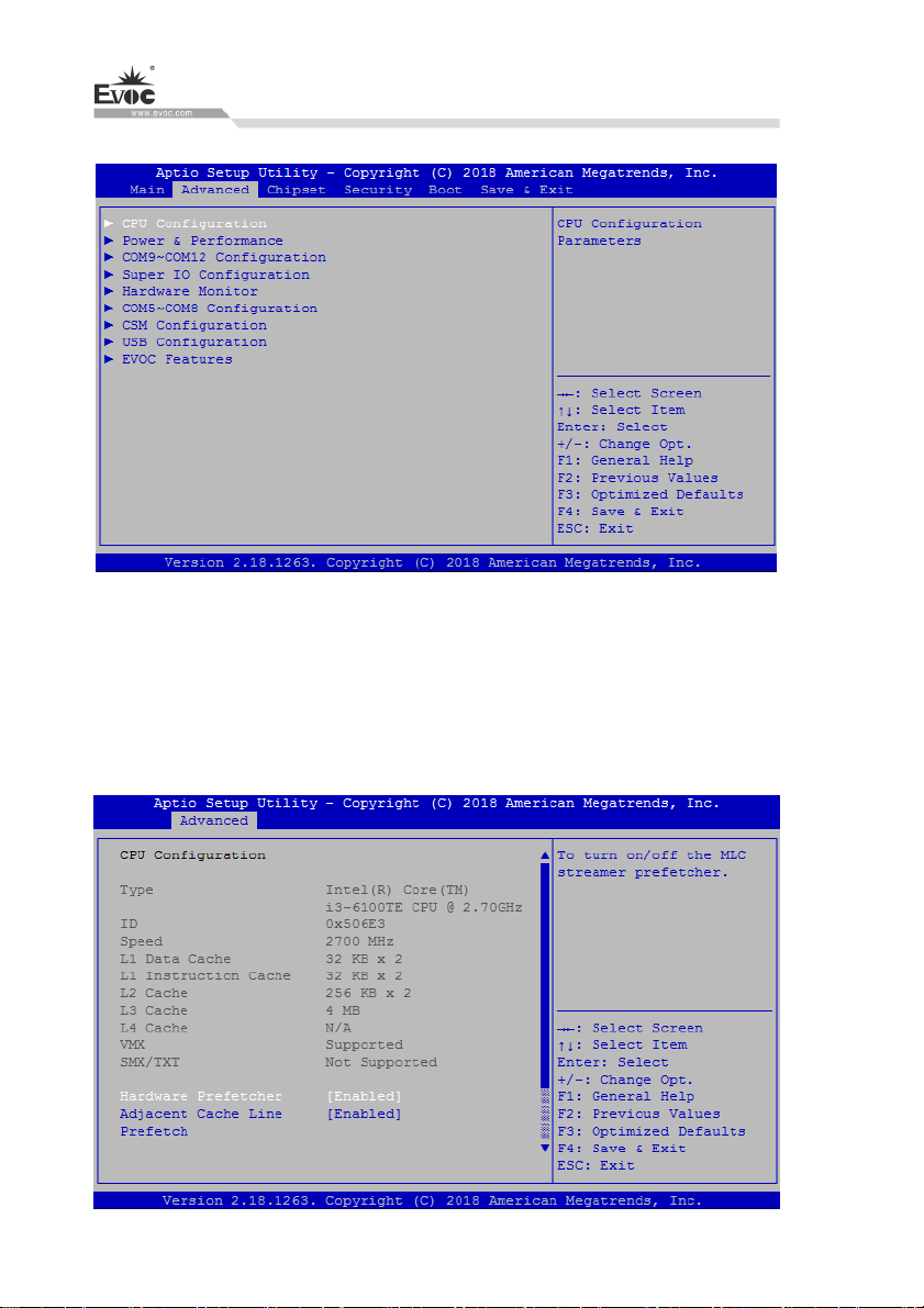
Advanced
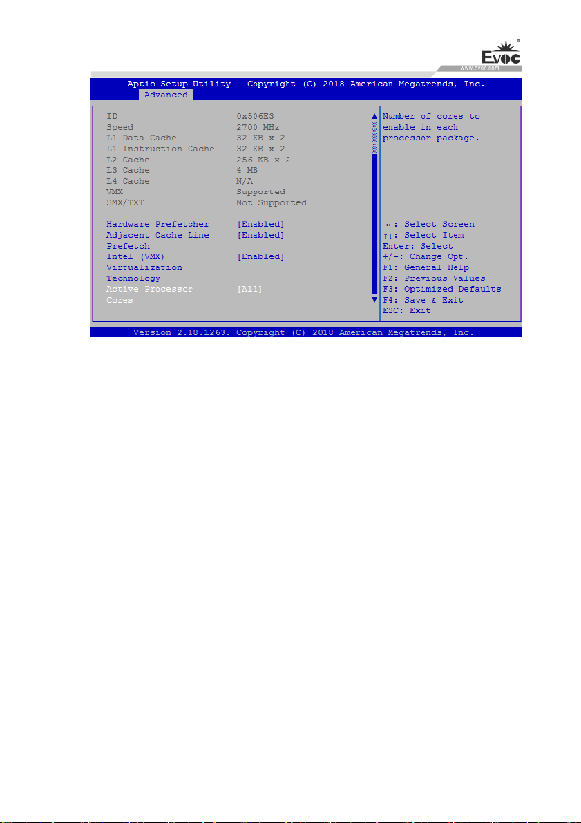
CPU Configuration
This option displays related information and functions of CPU. Please note that
the CPU specifications including models, working frequency, number of
processor cores, ultra-threading technology and virtualization technology are
related to the CPU installed; different families of CPUs will display different
information.
BIOS Setup
· 36 · W15 SERIES
Page 46
BIOS Setup
Hardware Prefetcher
Control switch of MLC prefetcher function.
Adjacent Cache Line Prefetch
Control switch of adjacent cache line prefetch.
Intel Virtualization Technology
The control switch of Intel Virtualization Technology function.
Active Processor Cores
To configure number of active processor cores.
Power & Performance
This item displays power consumption information and performance setup
related to CPU.
W15 SERIES
· 37 ·
Page 47
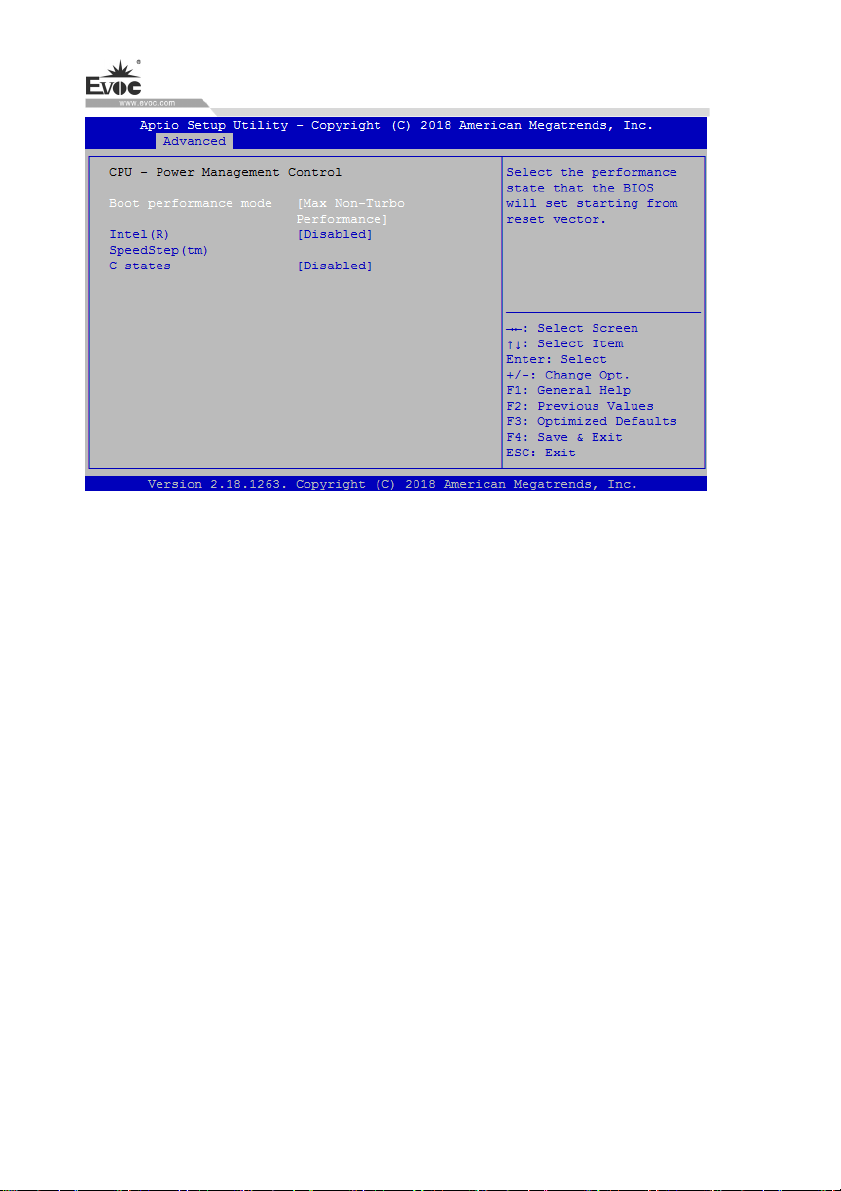
Boot performance mode
Enable performance mode selection.
Intel(R) SpeedStep(tm)
BIOS Setup
Intel SpeedStep control switch.
CPU C states
Switch for CPU C states, a status switch for energy saving and power
consumption reduction.
· 38 · W15 SERIES
Page 48
BIOS Setup
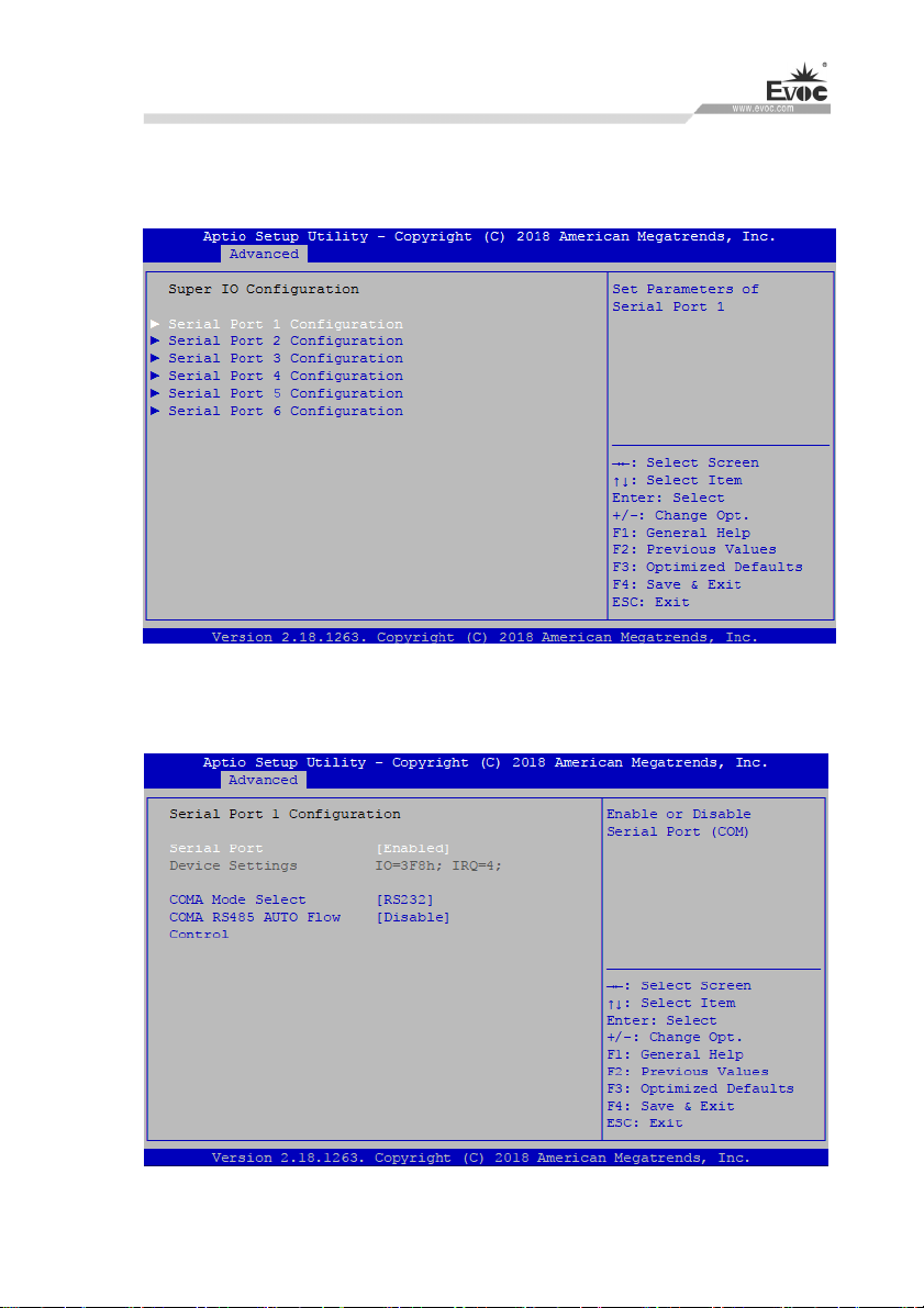
Supe
r IO Configuration
This item provides COM ports (COM1~6) of this platform.
Serial Port 1~6 Configuration
W15 SERIES · 39 ·
Page 49
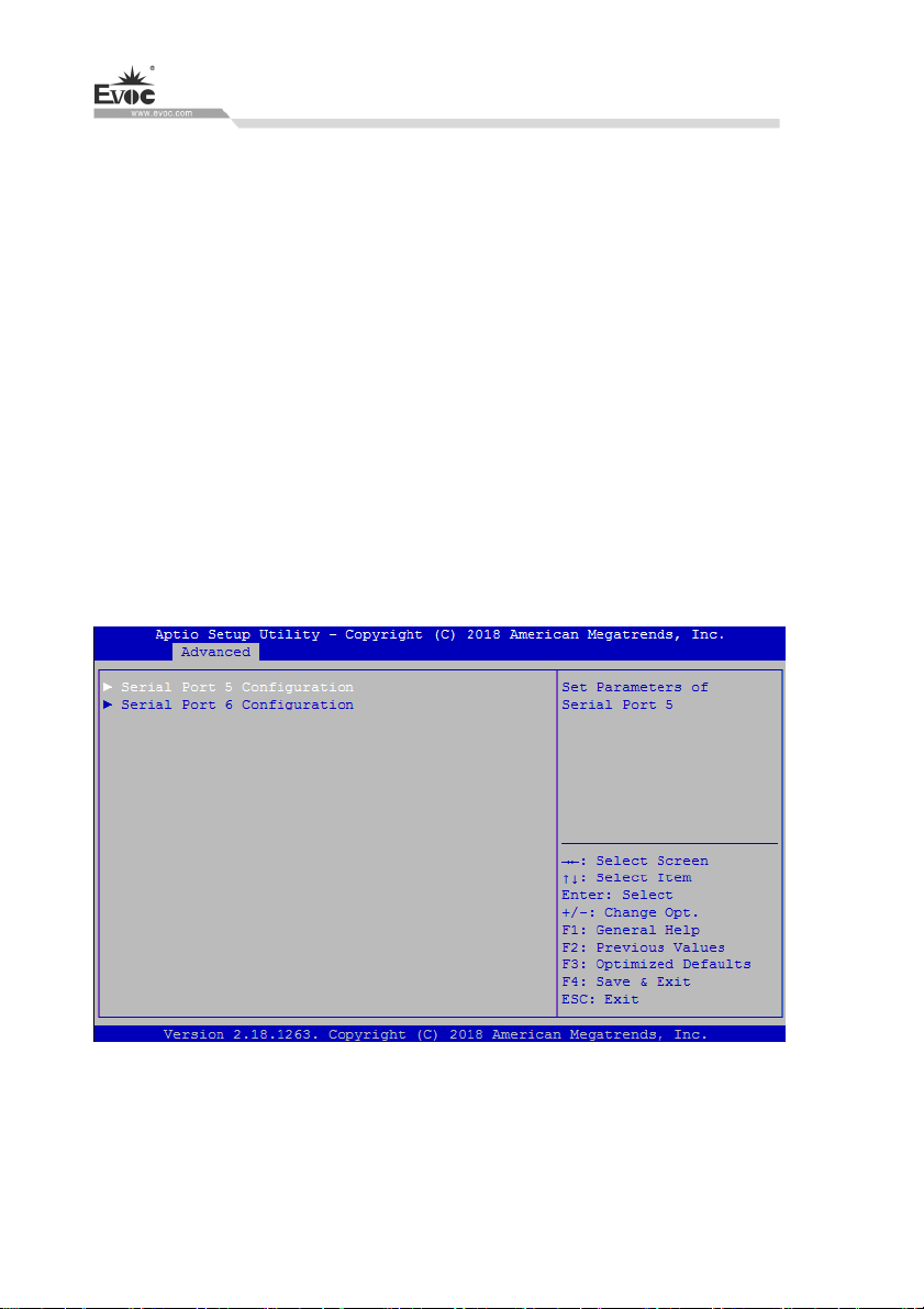
S
erial Port
Control switch of current COM port.
Device Settings
To indicate current resource configuration of COM ports.
COMA Mode Select
COM port mode selection.
COMA RS485 AUTO Flow
Automatic flow control switch of COM port.
COM5~COM6 Configuration
BIOS Setup
· 40 · W15 SERIES
Page 50
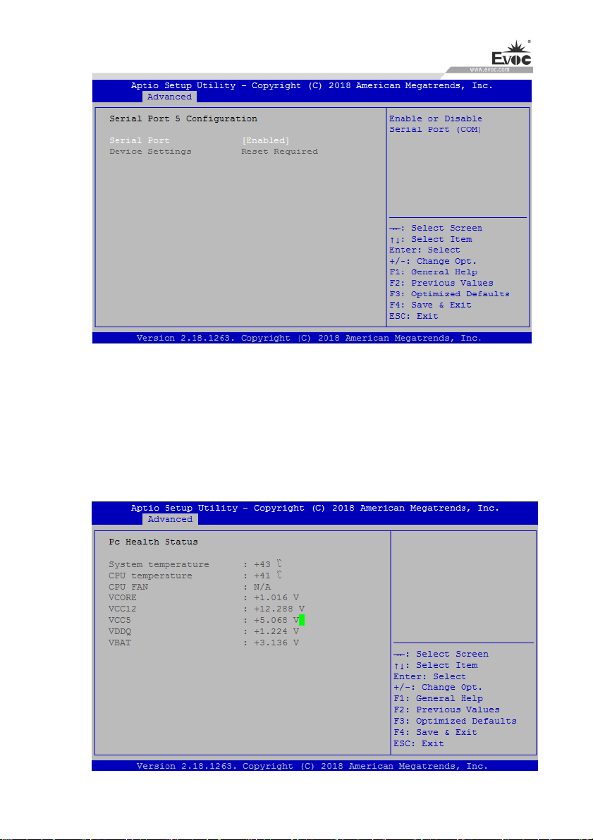
BIOS Setup
Serial Port
Control switch of current COM port.
Device Settings
To indicate current resource configuration of COM ports.,Reset
Required.Displays that the COM port hardware is not connected.
HW Monitor
W15 SERIES · 41 ·
Page 51
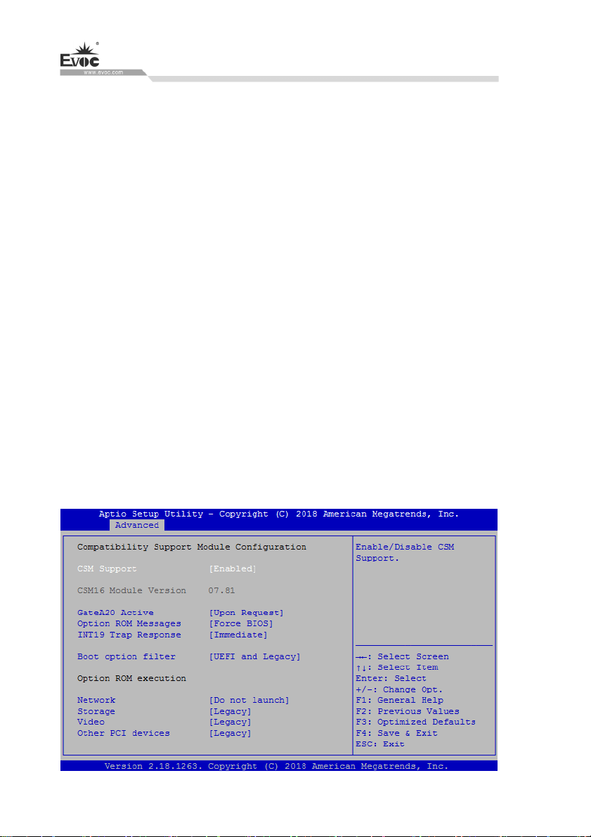
S
ystem temperature
To detect and display environment system temperature of the motherboard.
CPU temperature
To detect and display current CPU core temperature.
CPU FAN Speed
To display rotation speed of current motherboard CPU fan (CPUFAN1).
VCORE
To detect and display working voltage of current motherboard CPU core
voltage.
V12.0/V5.0/VDDQ
To detect and display working voltage values of various primary voltages of
ATX power supply.
VBAT
To detect and display voltage value of current motherboard battery.
BIOS Setup
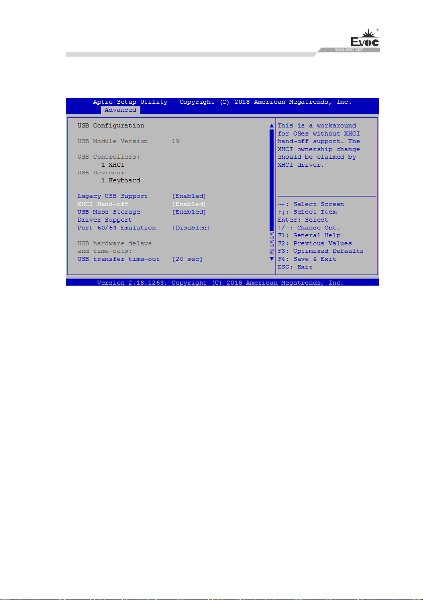
CSM Configuration
Configuration related to Legacy device compatibility.
· 42 · W15 SERIES
Page 52
BIOS Setup
USB Configur
This option provides configuration about USB controller.
Legacy USB Support
This option is used to support legacy USB devices (keyboard, mouse, storage
ation
device, etc). When it is set to Enabled, the USB devices can be used in the OS
that does not support USB, such as DOS. When it is set to Disabled, the legacy
devices cannot be used in the OS that does not support USB.
Note: USB can be used in EFI application, such as in Shell.
EVOC Features
This option provides configuration of EVOC special functions (“FMI” for
short).
W15 SERIES · 43 ·
Page 53
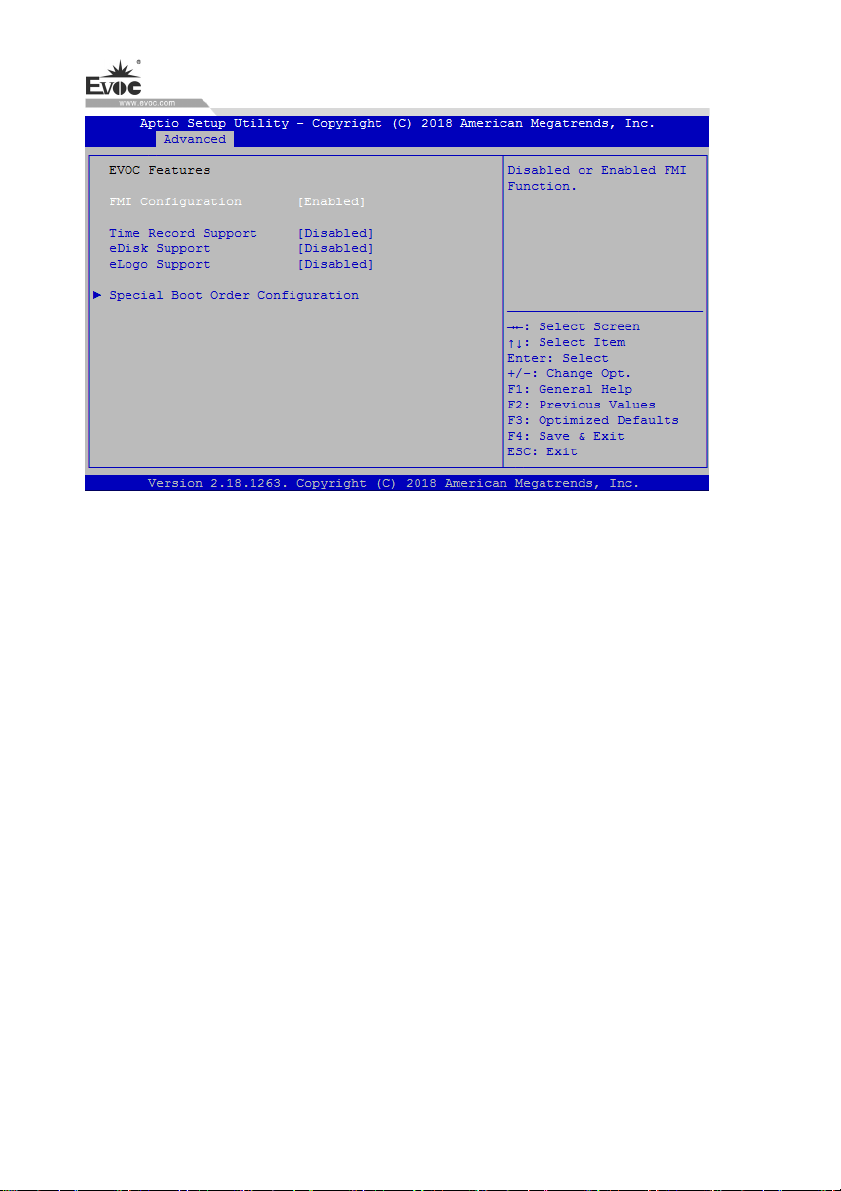
FMI Configuration
The general switch of FMI function, used to control whether EVOC Features
are supported.
Time Record Support
BIOS Setup
This option is used to record the operation time of motherboard.
eDisk Support
This option is used to enable or disable eDisk.
eLogo support
This option is used to change bootup Logo. Only when eDisk Support is enabled,
can this function be realized. The format of LOGO image must be BMP, and the
file name must be LOGO.BMP.
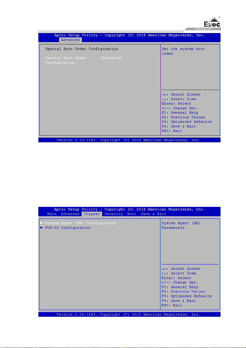
Special Boot Order Configuration
This option provides EVOC special boot order configuration.
· 44 · W15 SERIES
Page 54
BIOS Setup
Special Boot Order Configuration
The control switch of EVOC special boot order function. Only when this option
is set to “Enabled”, can the boot order be configured.
Chipset
This option provides configuration about platform chipset.
W15 SERIES · 45 ·
Page 55
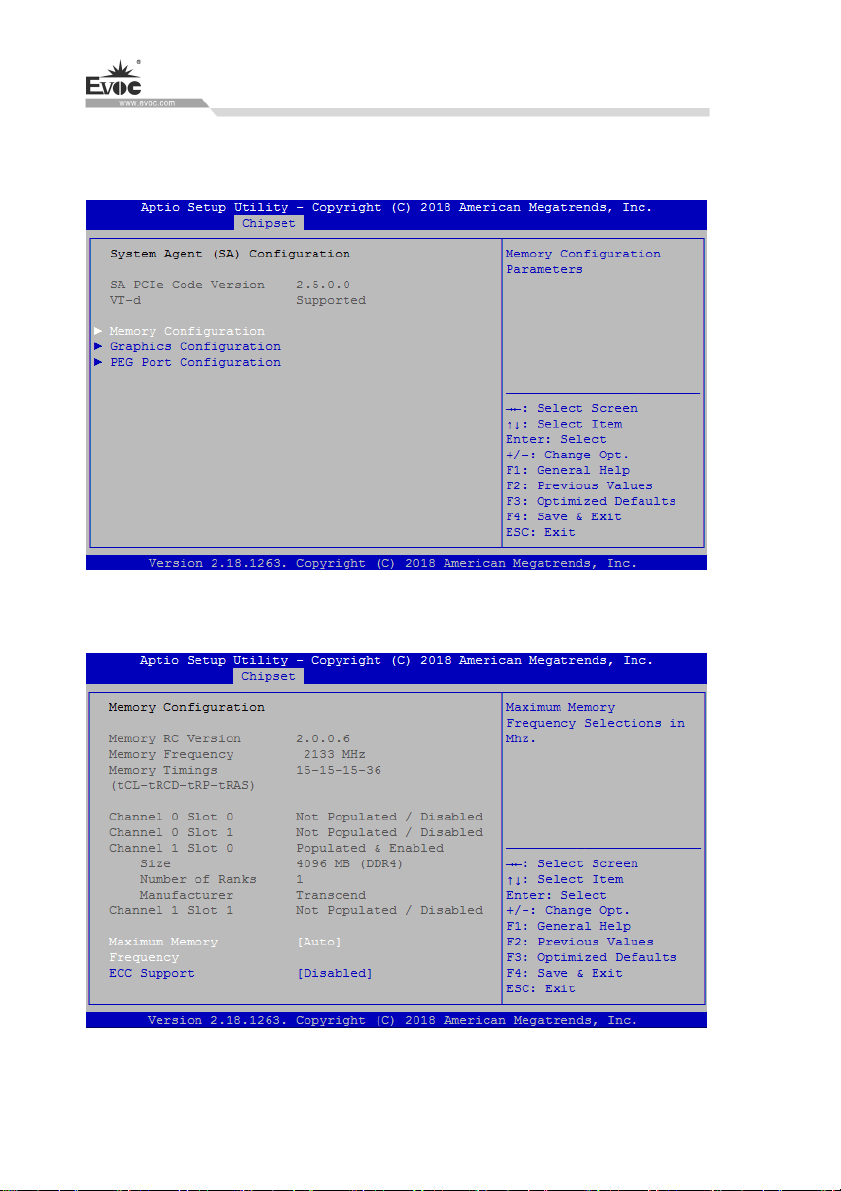
System Agent(SA) Configuration
BIOS Setup
This optio
Memory Configuration
n provides configuration of System Agent function.
Maximum Memory Frequency
Maximum mem
· 46 · W15 SERIES
ory frequency setup.
Page 56
BIOS Setup
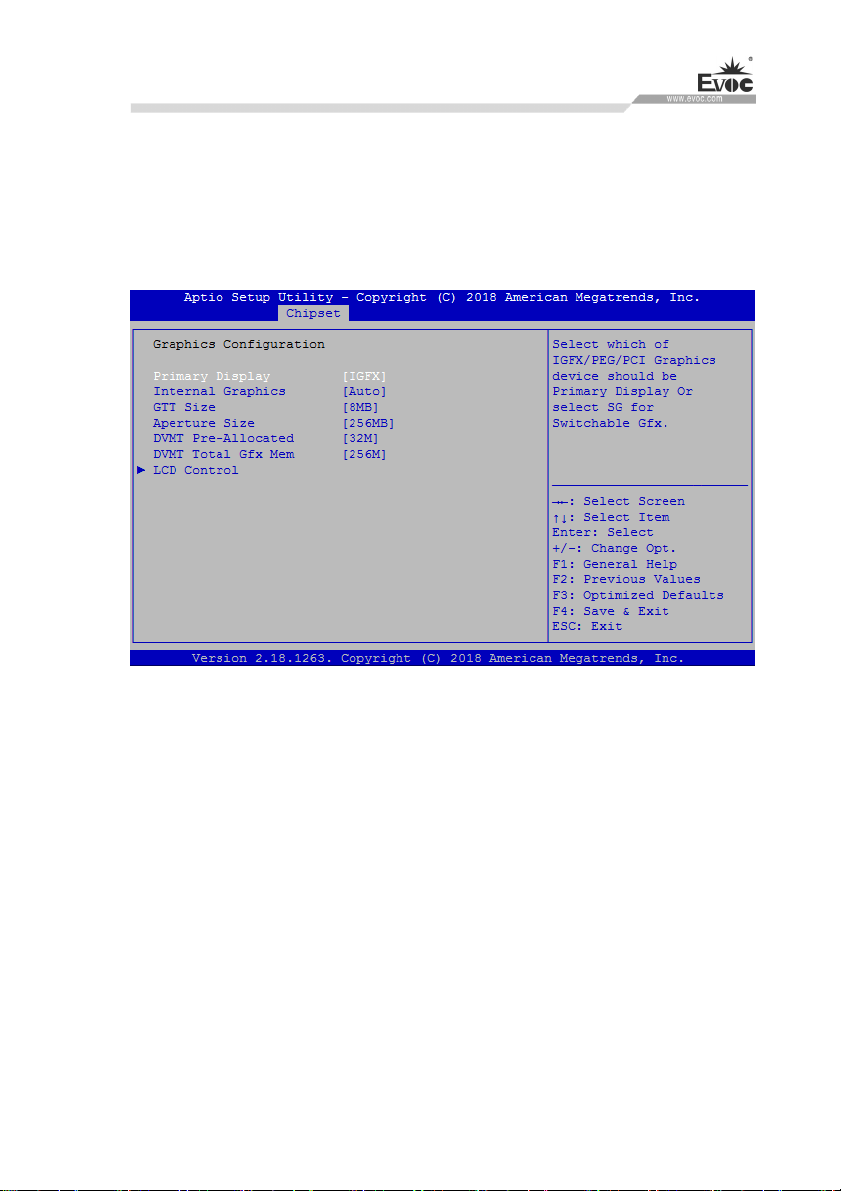
ECC Support
emory
M
Graphics Configuration
ECC support setup.
Primary Display
Control switch of pr
Internal Graphics
The control
GTT Size
To set up capaci
Aperture Size
To set up video memory
DVMT Pre-Allocated
To set up shared initial va
switch of integrated graphics card.
imary display.
ty of video memory of integrated graphics card.
capacity of integrated graphics card.
lue of video memory.
W15 SERIES · 47 ·
Page 57
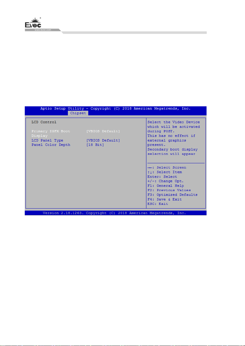
DVMT Total Gfx Mem
BIOS Setup
To set up the m
LCD Control
D
isplay control option.
LCD Control
Primary IGFX Boot Displa
y
aximum value of share video memory.
To set first display outpu
LCD Panel Type
To set resolution of th
Panel Color Depth
S
et the bit number of LCD screen.
Graphics Configuration
· 48 · W15 SERIES
e output.
t.
Page 58
BIOS Setup
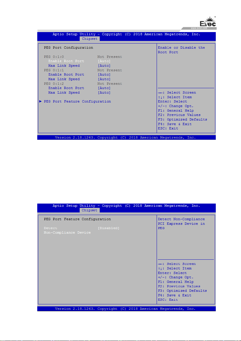
Enable Root Port
Enable or disable PEG Port
Max Link Speed
Maximum connection speed selection.
PEG Port Feature Configuration
W15 SERIES · 49 ·
Page 59
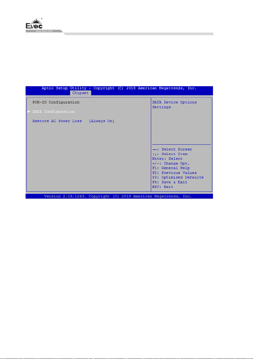
Detect Non-Compliance Devcie
BIOS Setup
Detects non-com
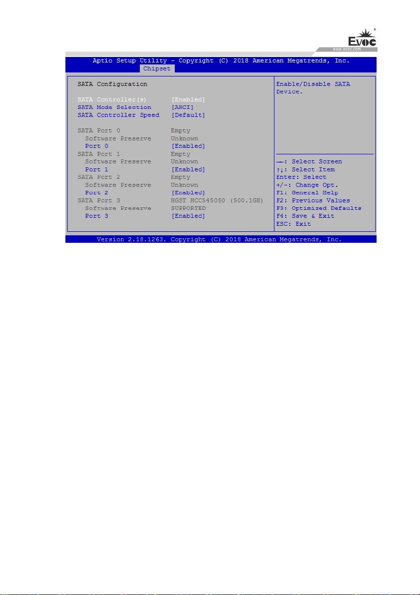
PCH-IO Configuration
This option provides function configuration of Intel PCH chip.
Restore AC Power Loss
This option could set the system status when the computer is re-electrified after
patible equipment.
powered off under AC. Power Off: the system stays at power-off status; Power
On: the system is automatically powered on; Last State: the system return to the
status before power disconnection.
SATA Configuration
This option shows the information of HDD connected to the motherboard. It
dynamically detects whether there are SATA devices on the motherboard. If a
device is connected with the corresponding port, it will display the SATA device
type. Otherwise, it will display “Empty”.
· 50 · W15 SERIES
Page 60
BIOS Setup
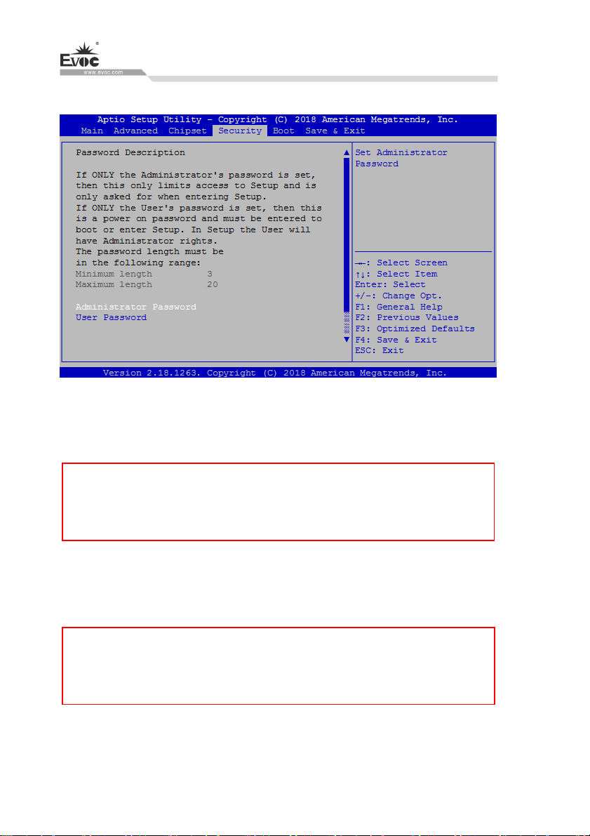
SATA Controller(s)
To enable or disable SATA Controller.
SATA Mode Selection
SATA mode selection. This platform provides AHCI and Intel RST Premium
modes. (Supported by some platforms). If RAID is to be configured, please
select Intel RST Premium mode.
SATA Controller Speed
SATA controller speed selection.
Port 0~3
The control switch used by SATA port.
W15 SERIES · 51 ·
Page 61
S
ecurity
Administrator Password
BIOS Setup
This option is used to set up
te: If only the administrator password is set, the pa
No ssword does not need
to be keyed in when entering into Setup program with User account. (i.e. at
this time, empty password is effective).
User Password
This option is used to
te: If only the user password is set, administrator
No authority can be
obtained after the password is keyed in when entering Setup program. At this
time, empty password is ineffective.
· 52 · W15 SERIES
administrator password.
set up user password.
Page 62
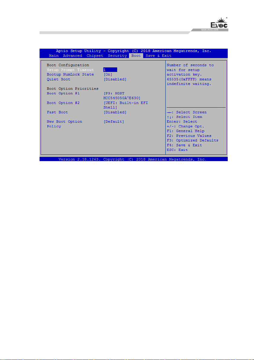
BIOS Setup
Boot
Setup Prompt Timeout
Setup prompt waiting tim
Bootup NumLock State
To set whether Numlock s
Quiet Boot
Boot mode se
Boot Option Priorities
This option is used to c
represents highest priority, #n represents lowest priority.
Fast Boot
To enable o
lection switch, used to enable or disable Quiet Boot function.
r disable Fast Boot function.
e after pressing F2.
tate is enabled during bootup.
onfigure priorities for system boot. Among them, #1
W15 SERIES · 53 ·
Page 63
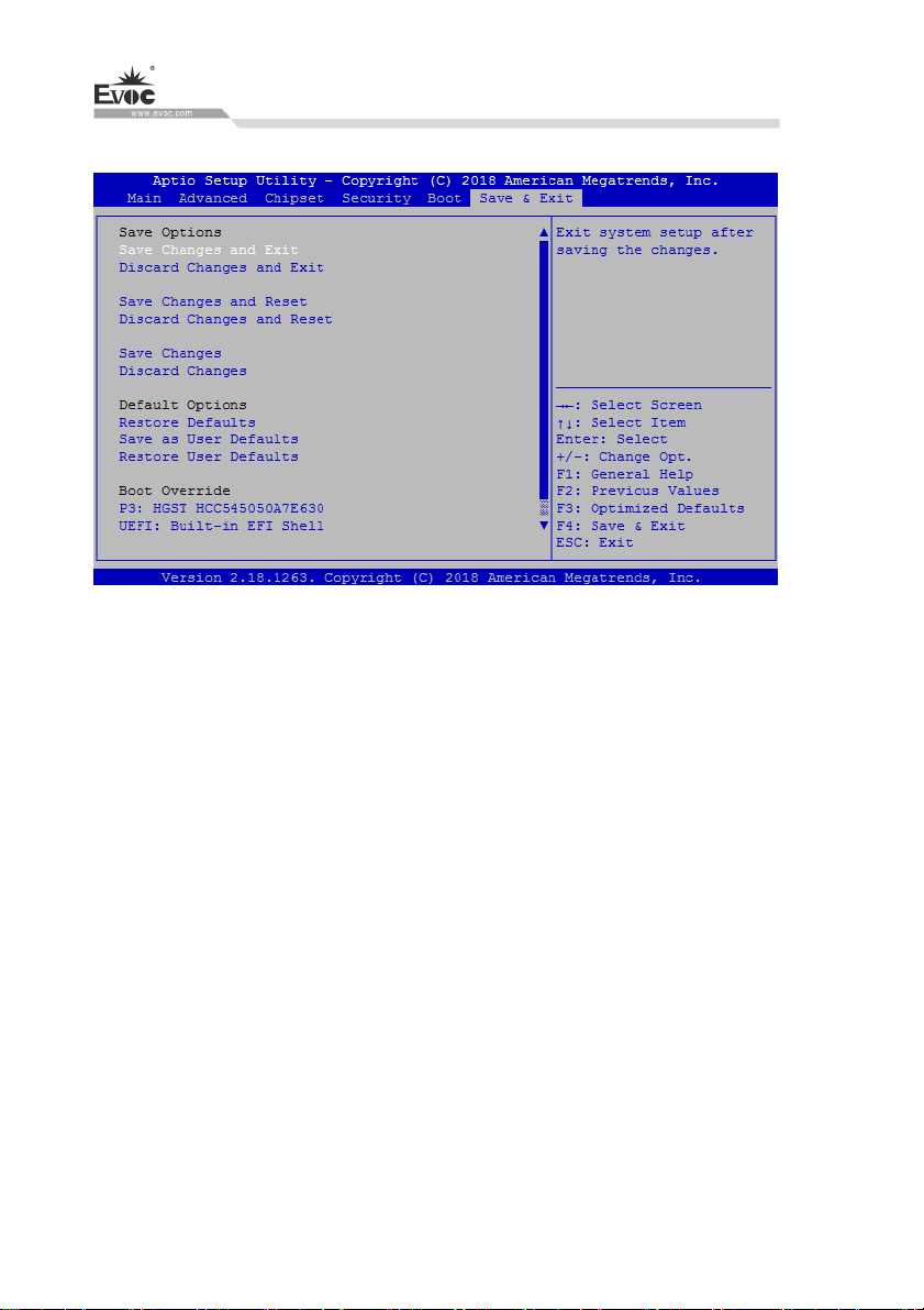
Save & Exit
Save Changes and Reset
This option is used to save changes and reset.
BIOS Setup
Discard Chang
This option is used to discard changes and rese
Restore Defualts
This option is used to restore defaults.
7.4 S FI under X86 Platform
ystem Resource Managed by UE
We define three kinds of system resources here: I/O port address, IRQ interrupt
number and Memory
IO Port Address
Only 16 IO address lines
for the system I/
foregoing 1024 (0000 ~ 03FFh) are used while the ports above 0400h are used
· 54 · W15 SERIES
es and Res
address.
O address space. In traditional ISA connector, only the
et
t.
are designed for X86, from 0 ~ 0FFFFh; there is 64K
Page 64
BIOS Setup
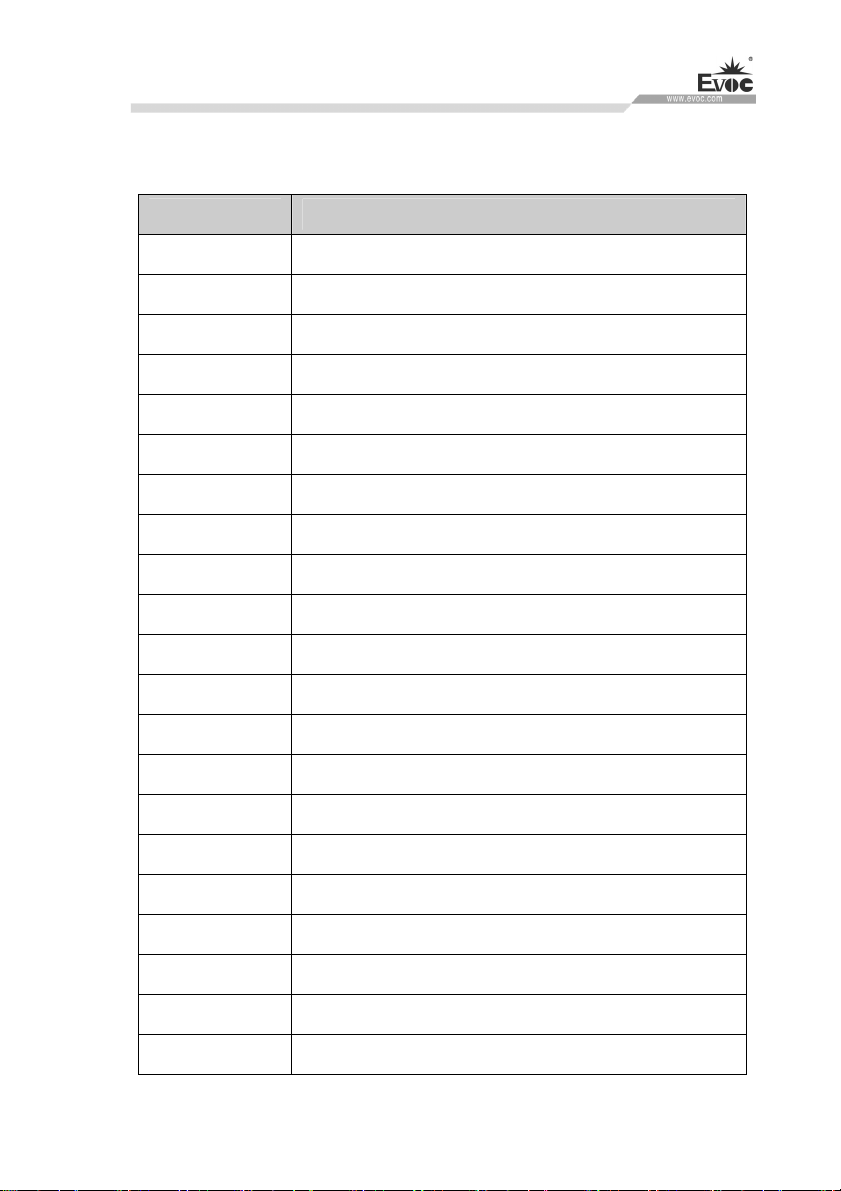
by PCI and EISA connectors. Each peripheral will occupy portion of the space.
The table below shows the I/O connectors used in X86 platform.
Address Device Description
0000-001F Direct memory accdess controller
0000-0CF7 PCI bus
0020-0021 Programmable interrupt controller
0024-0025 Programmable interrupt controller
0028-0029 Programmable interrupt controller
002C-002D Programmable interrupt controller
002E-002F Motherboard resources
0030-0031 Programmable interrupt controller
0034-0035 Programmable interrupt controller
0038-0039 Programmable interrupt controller
003C-003D Programmable interrupt controller
0040-0043 System timer
004E-004F Motherboard resources
0050-0053 System timer
0060-0060 PS/2 standard keyboard
0061-0061 Motherboard resources
0063-0063 Motherboard resources
0064-0064 PS/2 standard keyboard
0065-0065 Motherboard resources
0067-0067 Motherboard resources
0070-0070 Motherboard resources
W15 SERIES · 55 ·
Page 65

0070-0077 System CMOS/real time clock
0080-0080 Motherboard resources
0092-0092 Motherboard resources
00A0-00A1 Programmable interrupt controller
00A4-00A5 Programmable interrupt controller
00A8-00A9 Programmable interrupt controller
00AC-00AD Programmable interrupt controller
00B0-00B1 Programmable interrupt controller
00B2-00B3 Motherboard resources
00B4-00B5 Programmable interrupt controller
00B8-00B9 Programmable interrupt controller
00BC-00BD Programmable interrupt controller
00F0-00F0 Numeric data processor
BIOS Setup
02F8-02FF COM2
03B0-03BB Standard VGA graphics adapter
03C0-03DF Standard VGA graphics adapter
03F8-03FF COM1
04D0-04D1 Motherboard resources
04D0-04D1 Programmable interrupt controller
0680-069F Motherboard resources
0800-087F Motherboard resources
0A00-0A0F Motherboard resources
0A10-0A1F Motherboard resources
0A20-0A2F Motherboard resources
· 56 · W15 SERIES
Page 66

BIOS Setup
0A30-0A3F Motherboard resources
0D00-FFFF PCI bus
164E-164F Motherboard resources
1800-18FE Motherboard resources
1854-1857 Motherboard resources
E000-E01F Ethernet controller
E000-EFFF PCI Express standard Root Port
F000-F03F Standard VGA graphics adapter
F040-F05F Standard AHCI 1.0 Serial ATA controller
F060-F07F Standard AHCI 1.0 Serial ATA controller
F080-F083 Standard AHCI 1.0 Serial ATA controller
F090-F097 Standard AHCI 1.0 Serial ATA controller
FF00-FFFE Motherboard resources
FFFF-FFFF Motherboard resources
FFFF-FFFF Motherboard resources
FFFF-FFFF Motherboard resources
ent
IRQ Assignm Table
There are 15 interrupt sources of the system. Some have been occupied by the
system devices. Only the
devices. ISA device requests exclusive use of its interrupt. Only the plug and
play ISA devices can be assigned by the UEFI or the OS. And several PCI
devices can share one interrupt, which is assigned by UEFI or OS. Interrupt
assignment of some devices of X86 platform is shown in the table below, but it
does not show the interrupt source occupied by the PCI devices.
ones that are not occupied can be assigned to other
W15 SERIES · 57 ·
Page 67

Interrupt No. Device Description
IRQ0 System timer
IRQ1 PS/2 standard keyboard
IRQ2 Reserved
IRQ3 COM2
IRQ4 COM1
IRQ5 Reserved
IRQ6 Reserved
IRQ7 Reserved
IRQ8 System CMOS/read time clock
IRQ9 Reserved
IRQ10 Reserved
IRQ11 PCI data acquisition and signal processing controller
BIOS Setup
IRQ12 Microsoft PS/2 Mouse
IRQ13 Numeric data processor
IRQ14 Motherboard resources
IRQ15 Reserved
AP
IC
Advanced programmable interrupt controller. Most motherboards above P4
pport APIC and provide more than 16 interrupt sources, like IRQ16 -
level su
IRQ23; while some others can have up to 28 interrupt sources, such as
motherboard supporting PCI-X. However, relevant OS are required to enable
that function.
· 58 · W15 SERIES
Page 68

BIOS Setup
Memory Address
Address Device Description
000A0000-000BFFFF PCI BUS
000A0000-000BFFFF Standard VGA graphics adapter
8B000000-DFFFFFFF PCI bus
C0000000-CFFFFFFF Standard VGA graphics adapter
DE000000-DEFFFFFF Standard VGA graphics adapter
DF000000-FD01FFFF Ethernet controller
DF000000-DF0FFFFF PCI Express standard Root Port
DF200000-DF023FFF Ethernet controller
DF100000-DF10FFFF Multi-media audio controller
DF110000-DF11FFFF Universal Serial Bus (USB) controller
DF120000-DF123FFF Multi-media audio controller
DF124000-DF127FFF PCI memory controller
DF123000-DF129FFF Standard AHCI 1.0 Serial ATA controller
DF12A000-DF12A0FF SM bus controller
DF12B000-DF12B7FF Standard AHCI 1.0 Serial ATA controller
DF12C000-DF12C0FF Standard AHCI 1.0 Serial ATA controller
DF12E000-DF12EFFF PCI data acquisition and signal processing controller
DFFE0000-DFFFFFFF Motherboard resources
E0000000-EFFFFFFF Motherboard resources
FD000000-FDABFFFF Motherboard resources
FD000000-FE7FFFFF PCI bus
FDAC0000-FADCFFFF Motherboard resources
W15 SERIES · 59 ·
Page 69

FADA0000-FDAFFFFF Motherboard resources
FADE0000-FDAEFFFF Motherboard resources
FADF0000-FDAFFFFF Motherboard resources
FDB00000-FDFFFFFF Motherboard resources
FE000000-FE01FFFF Motherboard resources
FE036000-FE03BFFF Motherboard resources
FE410000-FE3FFFFF Motherboard resources
FED00000-FED003FF High precision event timer
FED10000-FED17FFF Motherboard resources
FED18000-FED18FFF Motherboard resources
FED19000-FED19FFF Motherboard resources
FED20000-FED3FFFF Motherboard resources
FED45000-FED8FFFF Motherboard resources
BIOS Setup
FED90000-FED93FFF Motherboard resources
FEE00000-FEEFFFFF Motherboard resources
FF000000-FFFFFFFF Intel(R) 82802 Firmware Hub Device
FF000000-FFFFFFFF Motherboard resources
· 60 · W15 SERIES
Page 70
Installing Expansion
8. Installing Expansion
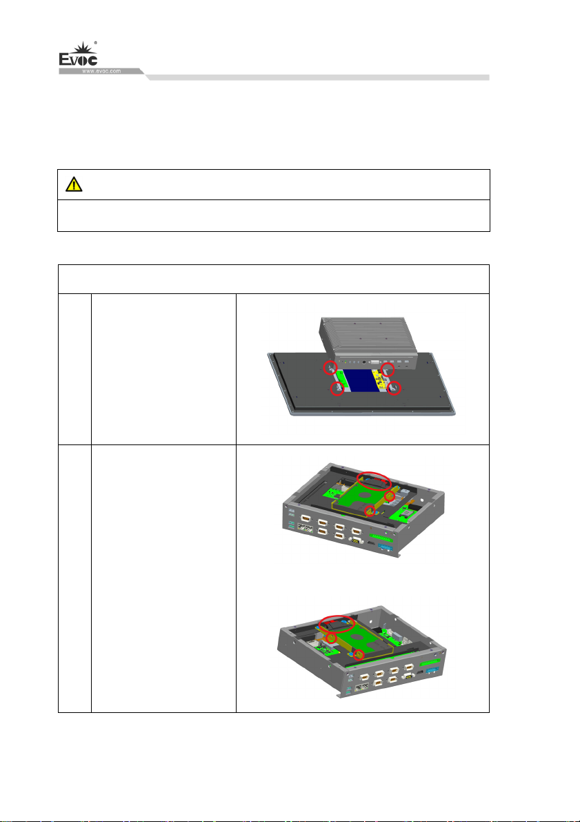
8.1 Opening the PC
Caution
Only authorized and qualified personnel is allowed to open the PC. During
warranty period, the users are only allowed to install expansion memory and
expansion card module.
Caution
The electronic components contained in the PC may be damaged by ESD.
Therefore, please take preventative measures before opening the PC. Please see the
“ESD Guideline” for regulations related to operation of ESD-sensitive components.
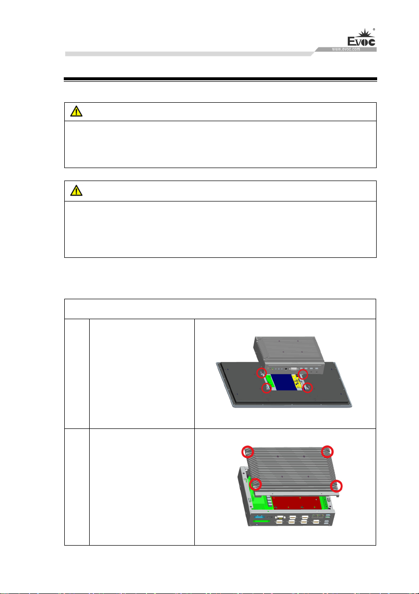
Preparation Work
Isolate the PC from the power source.
Steps to open the PC
Remove the four screws
shown in the picture, to
1
separate the display and
chassis.
Remove the four sunk
head screws shown in the
2
picture, and remove the
chassis cover
W15 SERIES · 61 ·
Page 71
8.2 HDD Expansion
Preparation Work
Disconnect the PC from power source.
Caution
The HDD can only be replaced by authorized personnel.
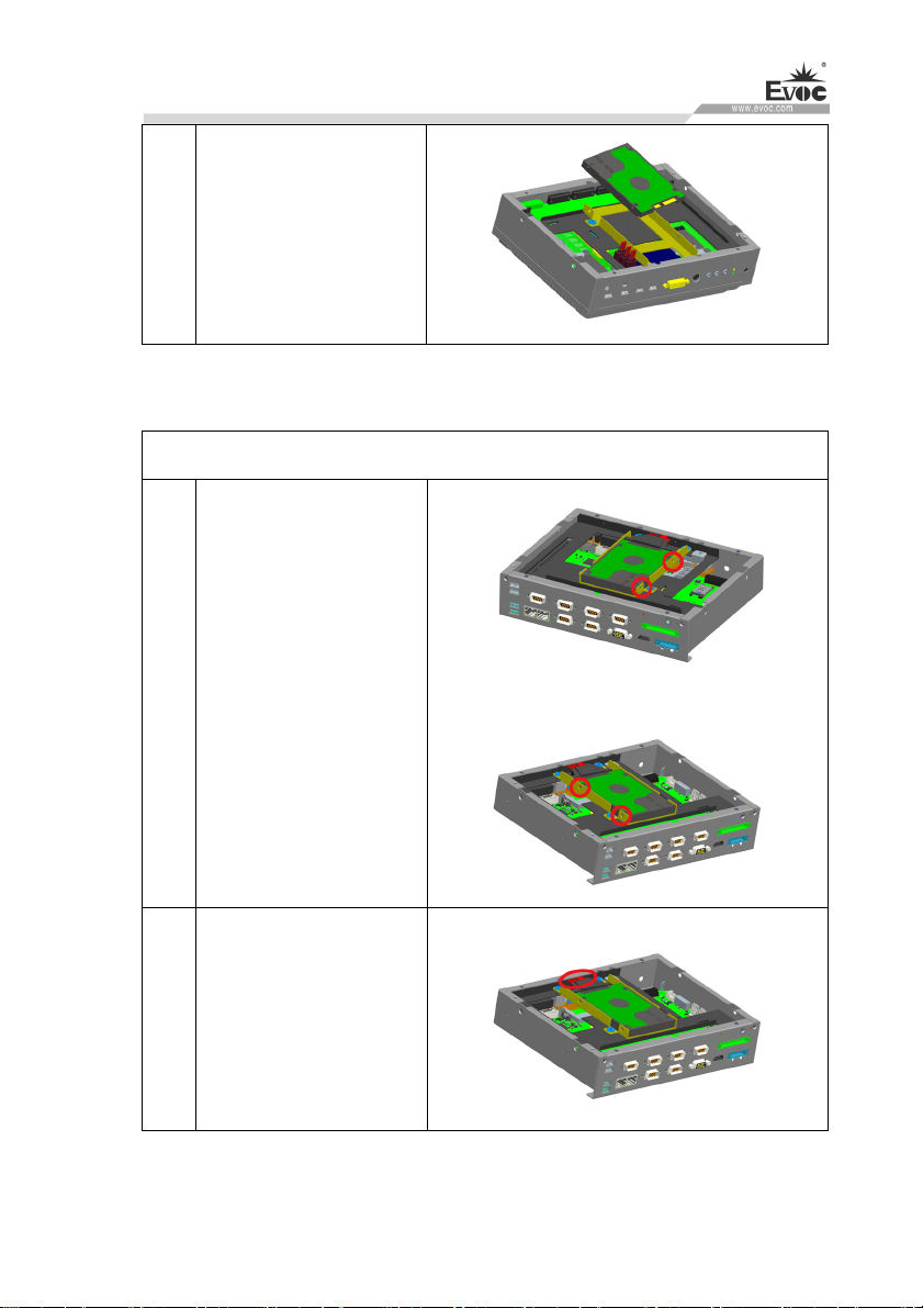
Removing the HDD
Steps to remove HDD
Remove the four screws
shown in the picture, to
1
separate the display and
chassis.
Installing Expansion
Remove the four screws
2
fixing the HDD, and pull
out the SATA cables
· 62 · W15 SERIES
Page 72
Installing Expansion
3 Remove the HDD
Installing the HDD
Steps to install HDD
Mount the HDD, and use
1
four screws to fasten it.
2 Connect the SATA cables
W15 SERIES · 63 ·
Page 73
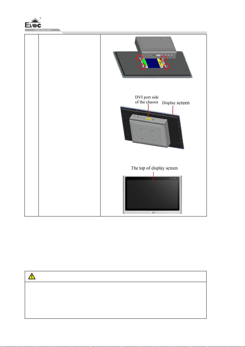
Cl
ose the the chassis and
display, and install the
four screws as shown in
the picture
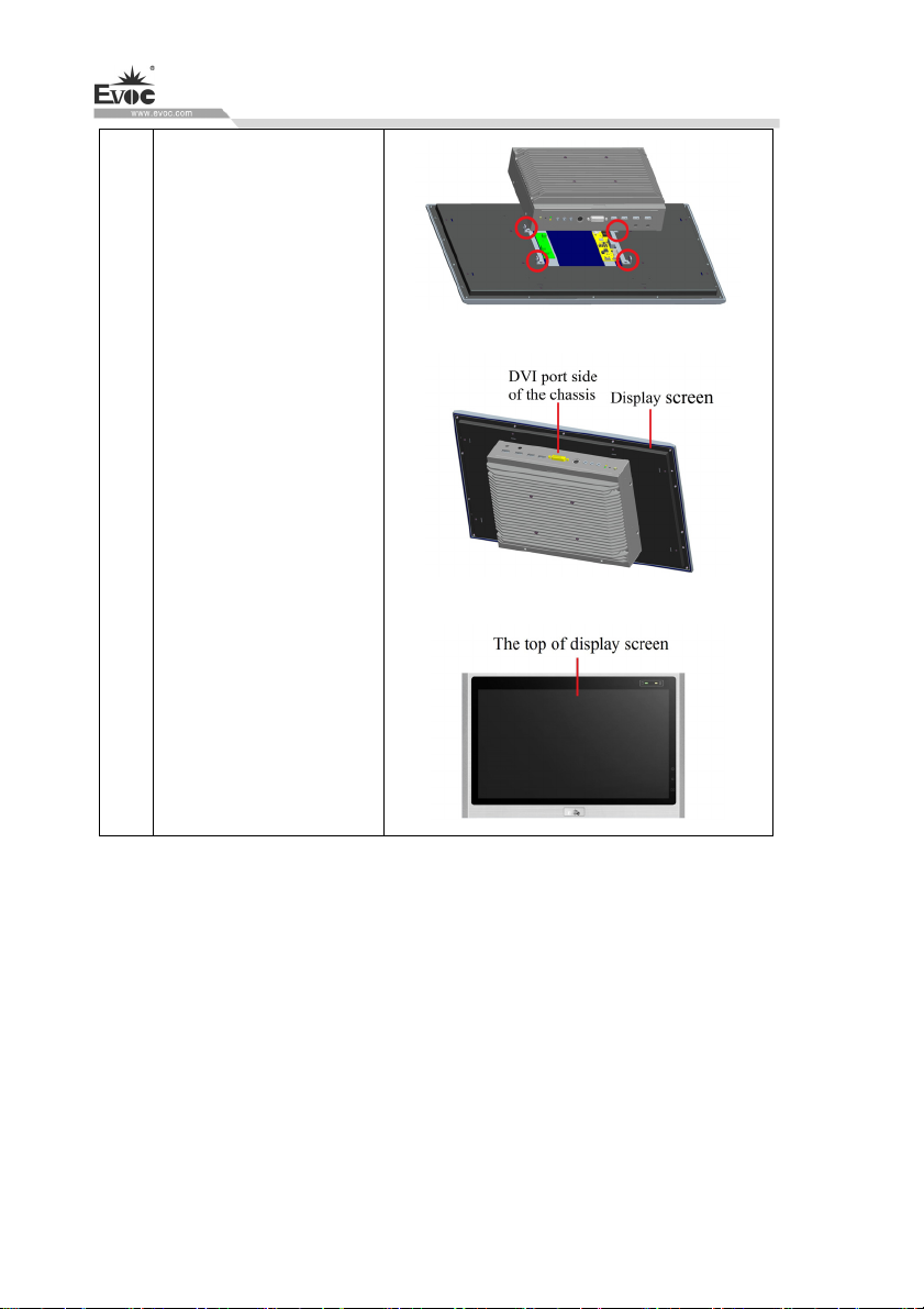
3
Note: The DVI port side
Installing Expansion
of the chassis should face
the top of display screen.
8.3 Installing/Removing the MiniPCI-E, M-SATA
Note: MiniPCI-E, M-SATA all support 3G/4G module.
Preparation Work
Disconnect the PC from power source.
Caution
The electronic components on the PCB are extremely sensitive to ESD. When
operating these components, make sure to take proper preventative measures.
Please see the “ESD Guideline” for regulations related to operation of
ESD-sensitive components.
· 64 · W15 SERIES
Page 74
Installing Expansion
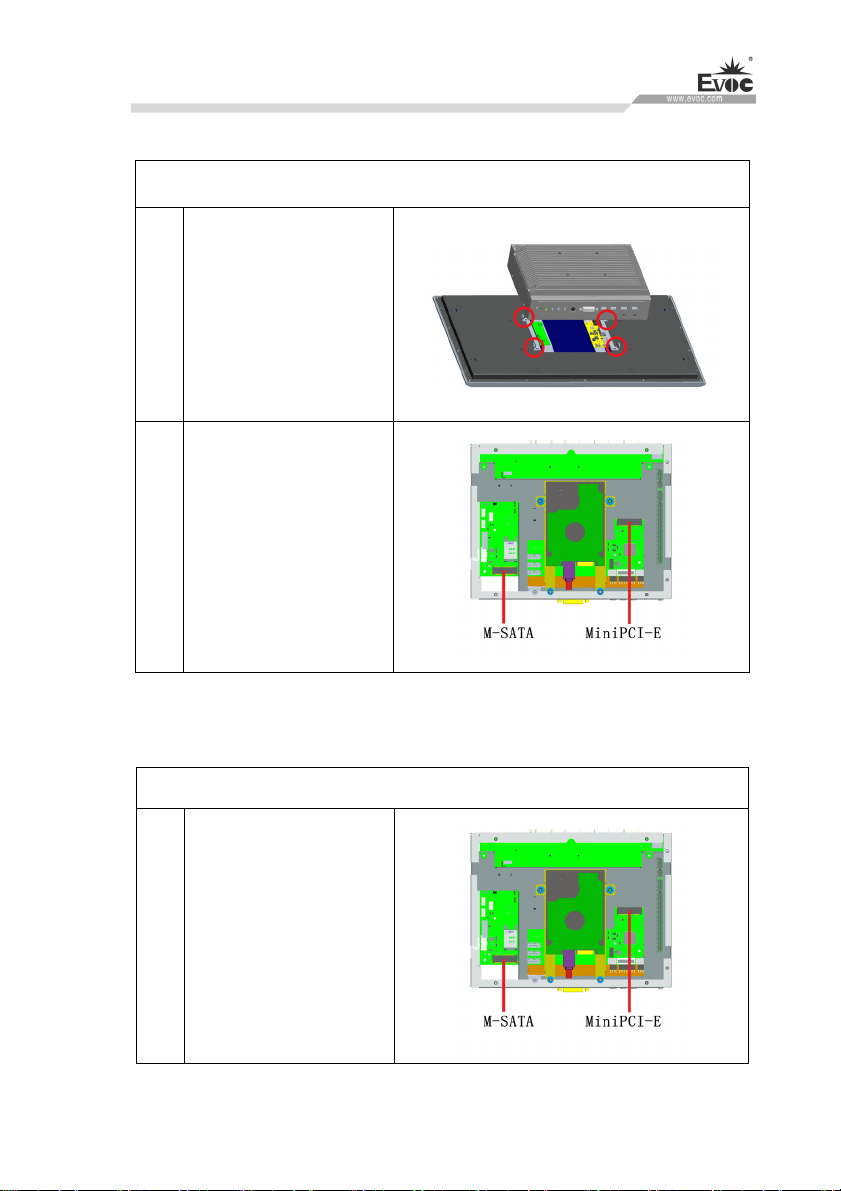
Removing the MiniPCI-E, M-SATA
S
teps to remove MiniPCI-E, M-SATA
Remove the four screws
shown in the picture, to
1
separate the display and
chassis.
Take out the MiniPCI-E,
2
M-SATA
Installing the MiniPCI-E, M-SATA
Steps to install MiniPCI-E, M-SATA
Place and assemble the
1
MiniPCI-E, M-SATA
according to the picture.
W15 SERIES · 65 ·
Page 75
Installing Expansion
Clos
e the the chassis and
display, and install the
four screws as shown in
2
the picture
Note: The DVI port side
of the chassis should face
the top of display screen.
· 66 · W15 SERIES
Page 76
Installing Expansion
8.4 SIM Card Expansion
Preparation Work
Disconnect the PC from power source.
Removing the SIM card
Steps to remove SIM card
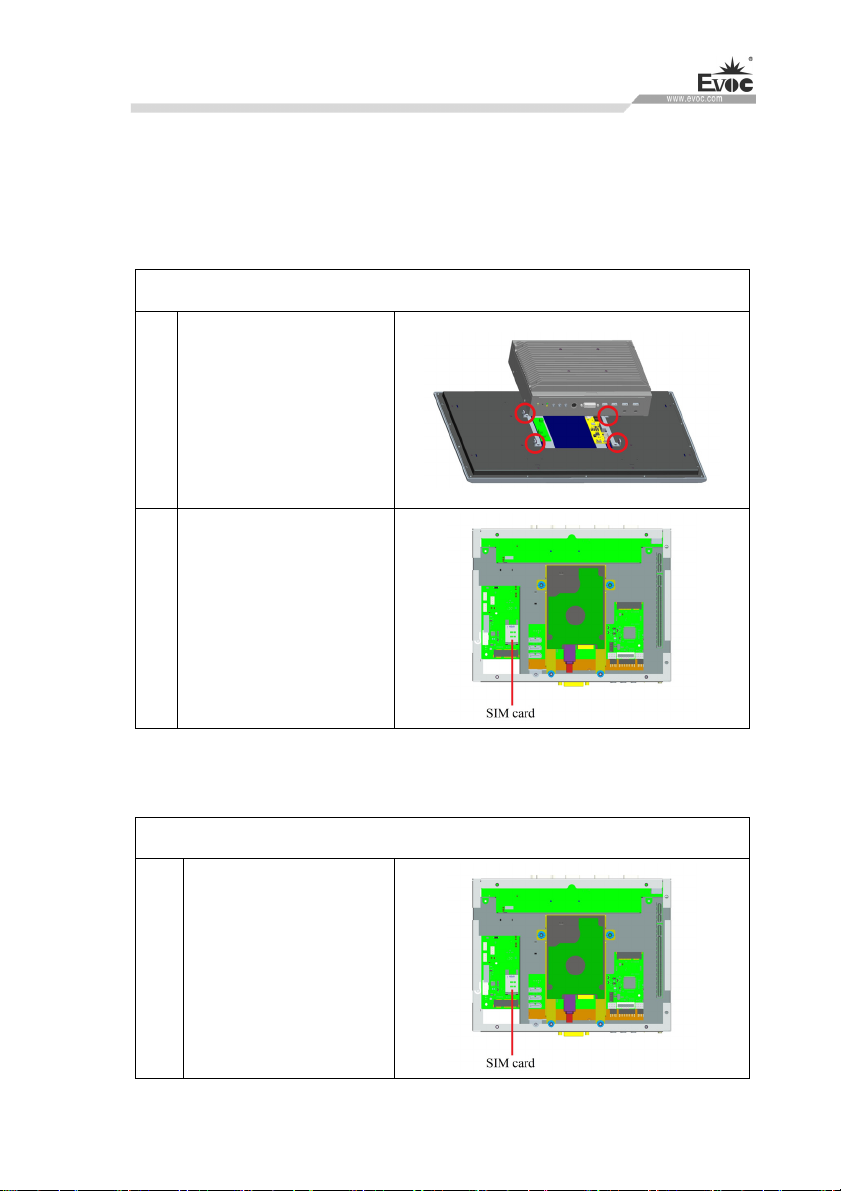
Remove the four screws
shown in the picture, to
1
separate the display and
chassis.
Take out the mini
2
M-SATA, and then take
out the SIM card.
Installing the SIM card
Steps to install SIM card
Place and assemble the
SIM card according to the
1
picture, and then
install the M-SATA
W15 SERIES · 67 ·
Page 77
Installing Expansion
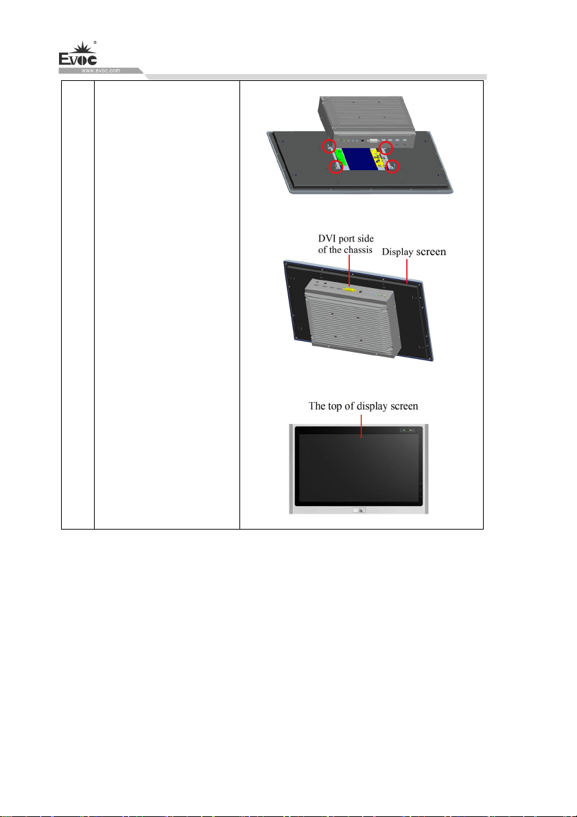
Cl
ose the the chassis and
display, and install the
four screws as shown in
2
the picture
Note: The DVI port side
of the chassis should face
the top of display screen.
· 68 · W15 SERIES
Page 78
Technical Parameters
9. Technical Parameters
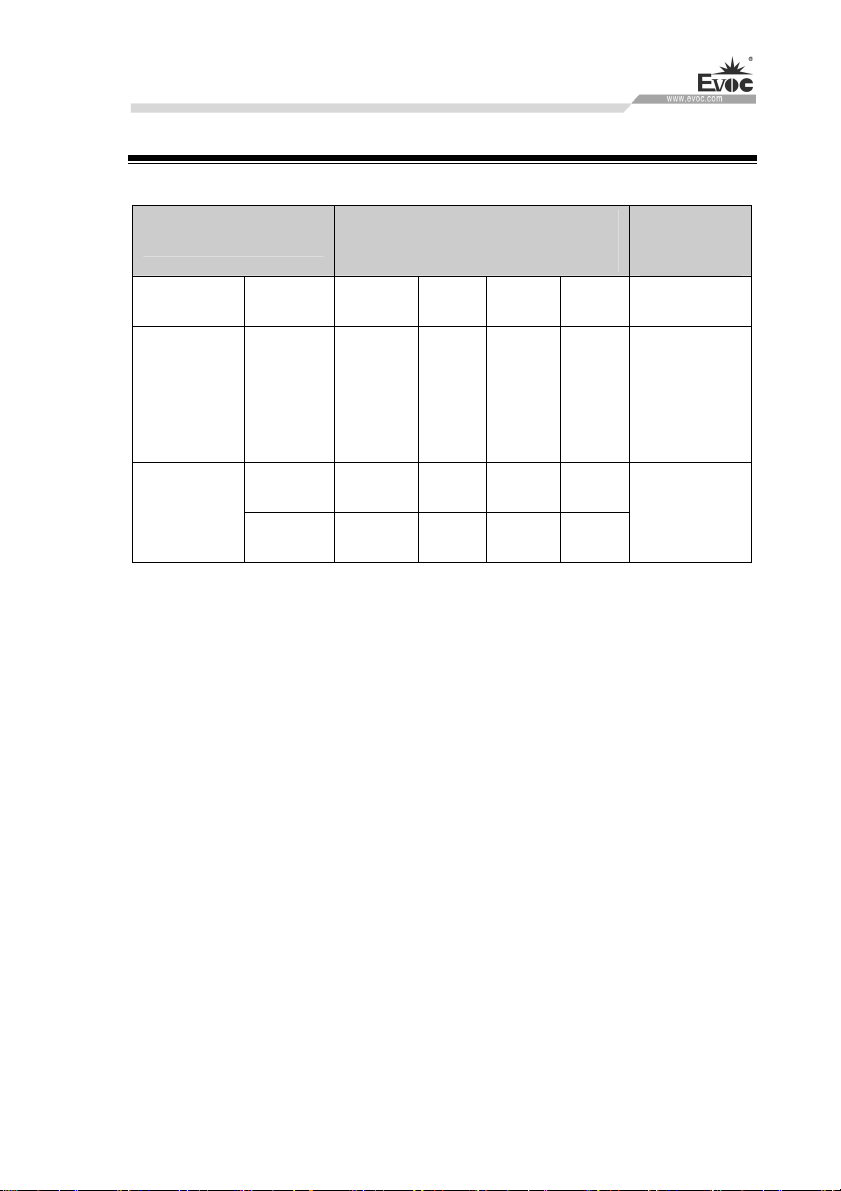
9.1 Maximum Power Consumption of Accessory Assemblies
Accessory Assemblies
USB2.0/3.0
device
MiniPCIE
Strong
current
Each slot 1.5 A 1.5 A 0.3 A 0.2 A
Total 1.5 A 1.5 A 0.3 A 0.2 A
Allowed maximum power
consumption
+5 V +3.3V +12 V -12 V
500mA/
800mA
-- -- --
Maximum
total power
10 W
(applicable to
all USB
devices)
8 W(for
whole PC)
W15 SERIES · 69 ·
Page 79
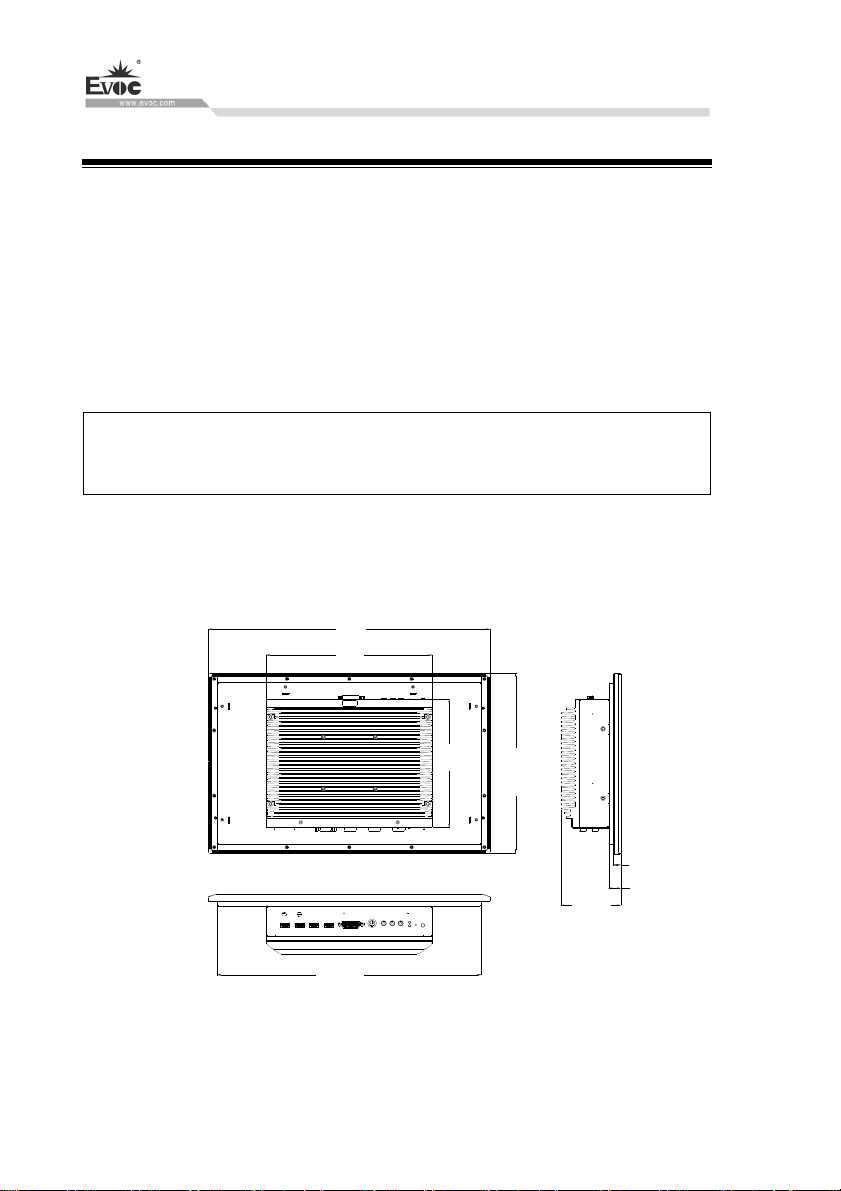
10. Dimensions Drawing
10.1 Dimensions Drawing Overview
This section includes the following dimensions drawings:
Product Outline Dimensions Drawing
Product Installation Dimensions Drawing
Recommended Dimensions Drawing for Hole Opening
Dimensions drawing of the product with mounting bracket
Note:
The unit used in the dimensions drawings is usually millimeter.
10.2 Product Outline Dimensions Drawing
407
240
Dimensions Drawing
· 70 · W15 SERIES
185
259.3
10.7
17.4
86.4
380.8
Unit: mm
Page 80
Dimensions Drawing
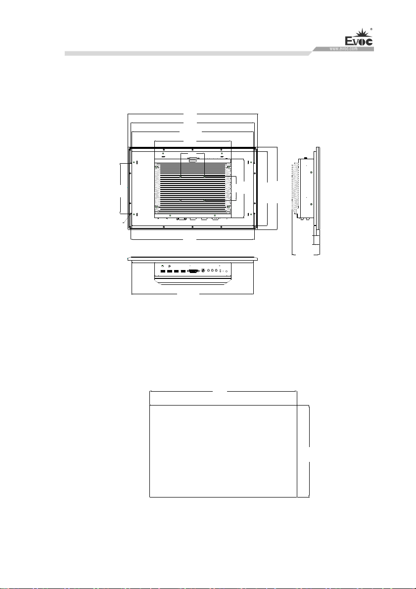
10.3 Installation Dimensions Drawing
10.3.1 Product Installation Dimensions Drawing
407
386
380.8
240
75
75
185
233.1
4XM
158
4
386
259.3
10.7
17.4
86.4
380.8
Unit: mm
10.3.2 Recommended Dimensions Drawing for Hole Opening
384
236
Unit: mm
W15 SERIES · 71 ·
Page 81
Dimensions Drawing
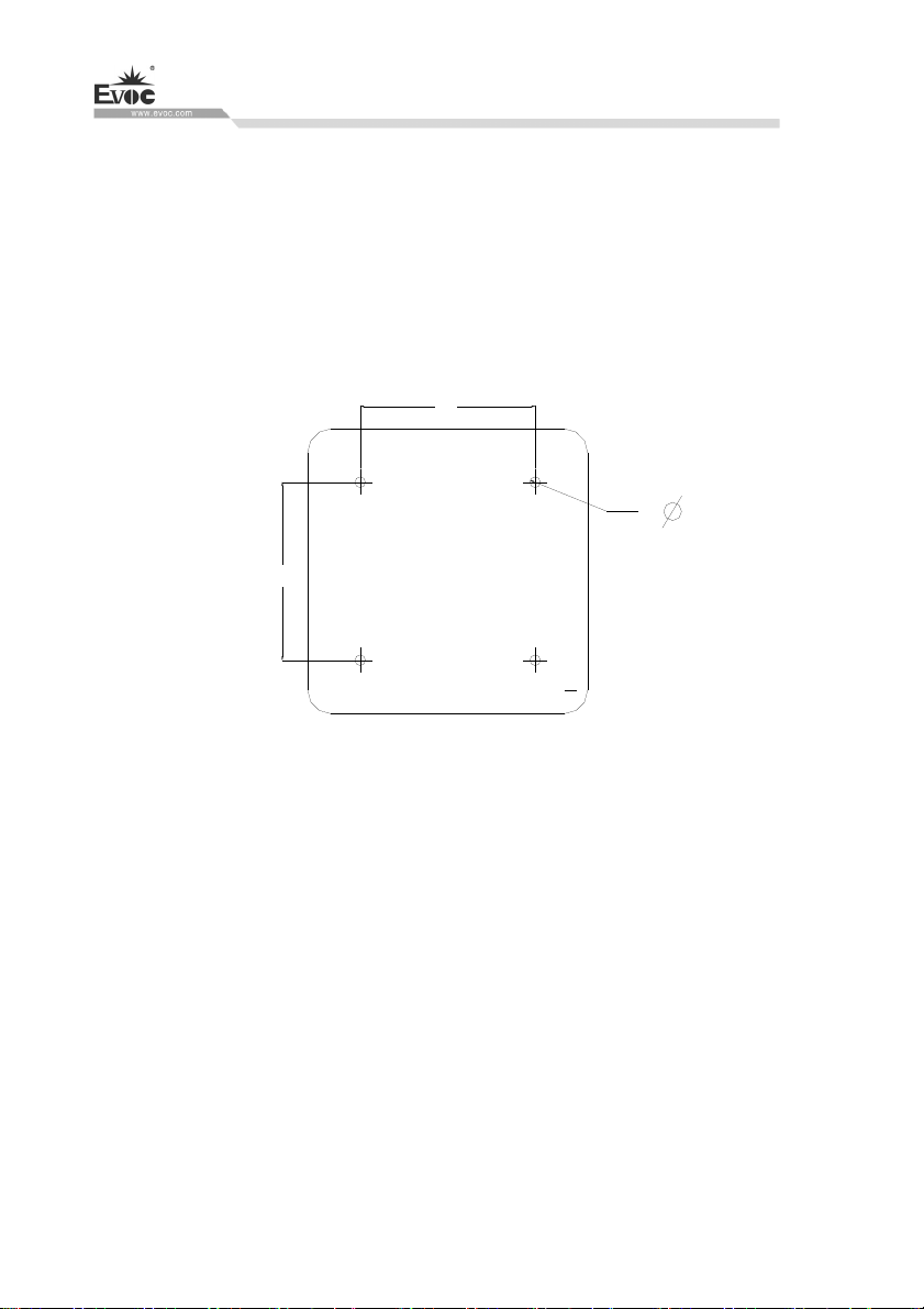
10.3.3 Dimensions Drawing of the Product with Mounting Bracket
(VESA bracket, to be purchased by customers themselves, and does not come with the
product)
Tighten the screws on the VESA bracket: truss head screw M4×8 S3 N/GB/T
9074.1-2002/Nickel-plated /Nylok /with flat washer, quantity: four.
75
4.5
4X
75
· 72 · W15 SERIES
Unit: mm
Page 82

Appendix
11. Appendix
11.1 Troubleshooting and Solutions
Common
Malfunctions
Reasons Troubleshooting and Solution
Please check whether the power
The device is not
operating
The screen is
black
No power supply
The input power supply
voltage is not within the
voltage range supported
by the system.
The screen is under
“power saving” mode
The luminance control is
set to “Black”.
connector is correctly connected.
Make sure the power switch is set
to ON.
Maybe the system is under
over-voltage or under-voltage
protection, please examine
whether the input voltage is within
the allowed range.
Press any key on the keyboard.
Increase the screen luminance by
luminance control. Please refer to
the instructions of the display for
detailed information.
Contact Technique Support if the
screen remains black after
Mouse cursor
cannot be moved
Mouse driver program
has not been loaded
implementing the above measures.
When starting the application
program, examine whether the
mouse driver has been correctly
installed. For more detailed
W15 SERIES · 73 ·
Page 83

Appendix
information, please refer to the
mouse or application program
manual.
Check whether the mouse cable is
connected to the system unit. If
adapter or mouse extension cord is
used, the connector should also be
ined. examThe mouse is not
Incorrect time or
date on PC
BIOS setting is
correct while the
time and date are
incorrect.
USB device has
no response
connected.
Press <F2> during boot priority
Invalid backup battery
USB port is not
supported by the
operating system.
If the measures above have been
executed and the mouse cursor
still cannot be seen on the screen,
please contact the technical
support team.
execution, and open BIOS Setup.
Set the time and date in the setup
menu.
In this circumstance, please
contact your technical support
team
No corrective measure.
· 74 · W15 SERIES
Page 84

Appendix
11.2 Common Alarm Information Analysis and Solution
Alarm Information Meaning and Solution
EFI BIOS product boot-up screen
indicates yellow alarm information:
“Warning system time is invalid, please
set it to right”
Motherboard CMOS time setup error
needs to be corrected.
After the motherboard is booted up, the
screen indicates: “Reboot and Select
proper Boot device or Insert Boot Media
in selected Boot device and press a key”
Award BIOS motherboard, during
boot-up POST, the screen indicates error
information “Keyboard error or no
keyboard present”
During EFI BIOS motherboard boot-up
POST, “Beep, beep, beep, beep, beep” 5
beeping sounds can be heard.
If the complete PC is equipped with
redundant power supply. After it is
booted, the PC power supply gives a
piercing alarm sound.
11.3 ESD Guideline
Current disk cannot boot, recheck the
system HDD connection cables, or
use optical drive for reinstallation of
operating system.
The motherboard or complete PC is
not connected to PS/2 or USB
keyboard, and the keyboard needs to
be correctly connected.
The motherboard or complete PC is
not connected to PS/2 or USB
keyboard, and the keyboard needs to
be correctly connected.
The redundant power supply is not
connected with two AC plugs. Power
off the PC and connect the two AC
plugs.
Definition of ESD:
All the electronic modules are equipped with large-scale integrated ICs or assemblies.
Due to their own design, these electronic components are extremely sensitive to
over-voltage, therefore, they are extremely sensitive to any electrostatic discharge.
ESD-sensitive assemblies/modules are usually called ESD devices. This is also the
W15 SERIES · 75 ·
Page 85
Appendix
internationally universal abbreviation for these devices.
The fo
llowing sign can be used to identify ESD modules:
Caution
ESD devices can be damaged by any voltage far lower than that can be felt by
human. If you do not release electrostatic charges on your body when you contact a
component of the device or carry out electrical connection for the device,
electrostatic voltage will be generated. The current of electrostatic discharge may
cause potential problem to the module. The damage may not seem serious for the
moment, but may lead to malfunction during later operation.
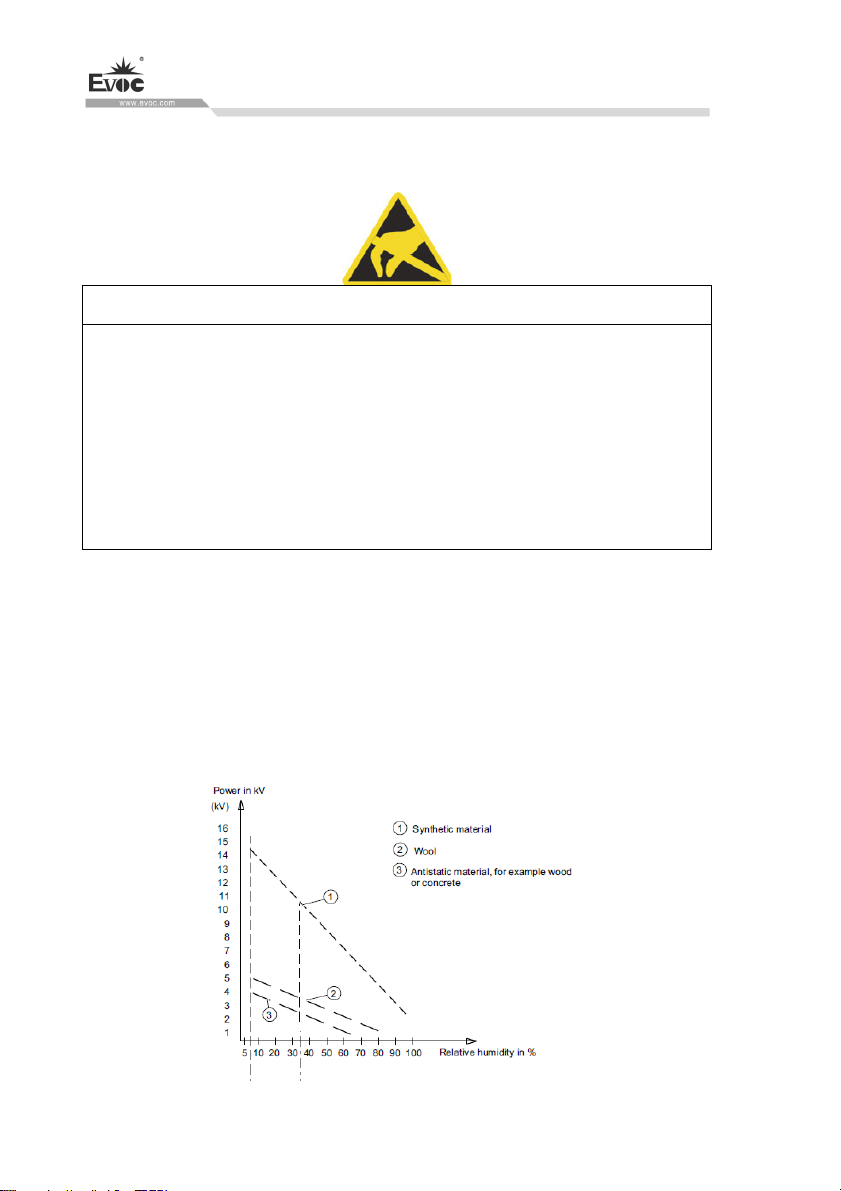
Electrostatic charging
Human body not connected to surrounding electrical level may have electrostatic
charging.
The following data indicates the maximum electrostatic voltages generated when
human bodies contact specific materials. These values are compliant with IEC 801-2
specifications.
· 76 · W15 SERIES
Page 86

Appendix
Electrostatic voltage on the operator
Basic protection measures to prevent electrostatic discharge:
Ensure excellent equipotential connection:
When holding an ESD-sensitive device, make sure your body, working area and
package are all grounded. This can prevent electrostatic charges.
Avoid direct contact:
Contact ESD-sensitive devices only when it is unavoidable (for example during
repair). Do not touch any chip pin or PCB circuit when holding a module. In this way,
the released electric energy will not affect the ESD-sensitive device.
Before handling the module, release charges on your body. They can be released by
touching a grounded metal component. Make sure a grounded measuring instrument
is used.
W15 SERIES · 77 ·
Page 87
PC Maintenance
12. PC Maintenance
12.1 Removal/Installation of Hardware Assembly
12.1.1 Carry out Maintenance
The PC can only be maintained or repaired by authorized personnel.
Warning
Unauthorized operation or repair for the PC may cause damage to the PC or
endanger safety of users.
Disconnect the PC from power source before opening the PC.
Only the system expansion devices designed for the PC can be installed. If other
expansion devices are installed, the PC may be damaged or safety requirements
and regulations related to radio frequency suppression may be breached. Please
contact technical support team or local distributor, to know the system
expansion devices that can be safely installed.
If the product is damaged due to installation or replacement of system expansion
device, the warranty will become invalid.
Responsibility Range
Our company shall not be held responsible for functional damage caused by use of
third-party device or assembly.
12.1.2 Preventative Maintenance
To maintain relatively high system availability, it is recommended to preventatively
replace the quick-wear parts. The table below give the time interval for replacement:
Assembly Time Interval for Replacement
HDD 3 years
CMOS backup battery 5 years
· 78 · W15 SERIES
Page 88
PC Maintenance
12.1.3 Replacing Backup Battery
Things to know before changing battery
Caution
Damage may exist!
Always use same type lithium battery or lithium batteries recommended by the
manufacturer.
Disposal
Caution
Battery to be discarded should be disposed according to local laws.
Preparation Work
Notes:
1.Note down the current BIOS Setup or save the settings to the user profile in the
BIOS Setup“Exit” menu.
2. BIOS Setup provides a list, where these information can be saved.
3. Disconnect the PC from power source.
Replacing Battery
Steps to replace battery
1 Loosen the four screws on the top cover, and open the top cover.
Pull out the battery connection
2
cable as shown in the picutre,
and remove the battery.
W15 SERIES · 79 ·
Page 89
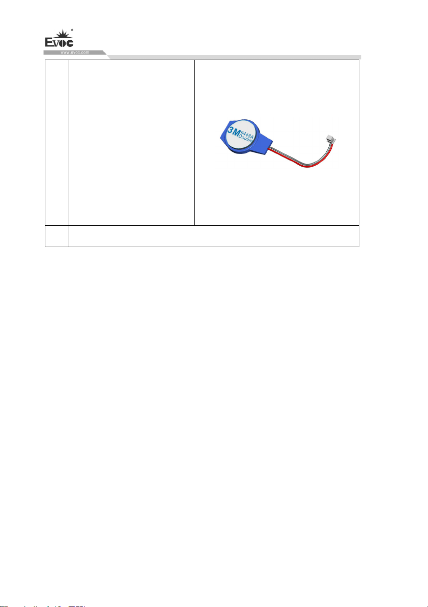
PC Maintenance
Rip off th
the new battery adhesive, stick
it on the corresponding
position on the motherboard,
3
and use tapes to fasten it, then
insert the battery cable into the
corresponding socket on the
motherboard.
4 Close the top cover and tighten it with screws.
e release paper on
12.2 Installing the Drivers
Regarding the installation of driver program of this product, please refer to the
enclosed CD.
When driver program cannot be installed, for example a yellow question mark or
exclamation mark appears, it is recommended to install latest patch package of
corresponding operating system, or directly install the operating system of latest
release version before installing the driver program.
· 80 · W15 SERIES
 Loading...