

Evo SEDONA 50551 Owner's Manual
OWNER’S MANUAL
RETAIN FOR FUTURE REFERENCE
TOLL FREE CUSTOMER SERVICE
1.888.800.1167
MODEL NUMBER: 50551
SERIAL NUMBER:
APPLICATION STANDARD
ASSEMBLY
OPERATING INSTRUCTIONS
CONDITIONING GUIDELINES
WARRANTY
SERVICE
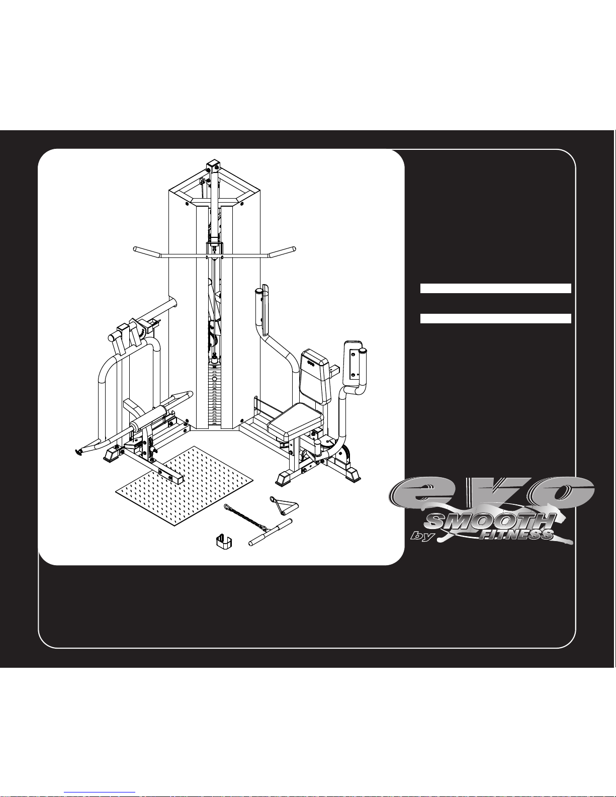
EVO SEDONA Home Gym

preassembly
-2-
BEFORE BEGINNING
Open the boxes
Y ou are now ready to open the boxes
of your new equipment. Make sure
to inventory all of the parts that are
included in the boxes. Check the
Parts List for a full count of the
number of parts included for this
product to be assembled properly.
If you are missing any parts or have
any assembly questions contact your
local Smooth Retailer.
Gather your tools
Before starting the assembly of
your unit, make sure that you have
gathered all the necessary tools you
may require to assemble the unit
properly . Having all of the necessary
equipment at hand will save time
and make the assembly quick and
hassle-free.
Clear your work area
Make sure that you have cleared
away a large enough space to
properly assemble the unit. Make
sure space is flat, level and free from
anything that may cause injury during
assembly. After the unit is fully
assembled, make sure there is a
comfortable amount of free area
around the unit for unobstructed
operation.
For future service or related
questions.
Please staple your receipt and/or
write in the name and phone number
of the retail store where you
purchased your EVO home gym.
Name:
Phone Number:
Receipt:
Invite a friend
Some of the assembly steps may
require heavy lifting. It is
recommended that you obtain the
assistance of another person when
assembling this product.
A MAJORITY OF THE LISTED HARDWARE IS ALREADY IN PLACE
ORDER NUMBER
50551-01
50551-02
50551-03
50551-04
50551-05
50551-06
50551-07
50551-08
50551-09
50551-10
50551-11
50551-12
50551-13
50551-14
50551-15
50551-16
50551-17
50551-18
50551-19
50551-20
50551-21
50551-22
1” 2” 3” 4”0
1/2
3/41/4
1/2
3/41/4
1/2
3/41/4
1/2
3/41/4
INCHES
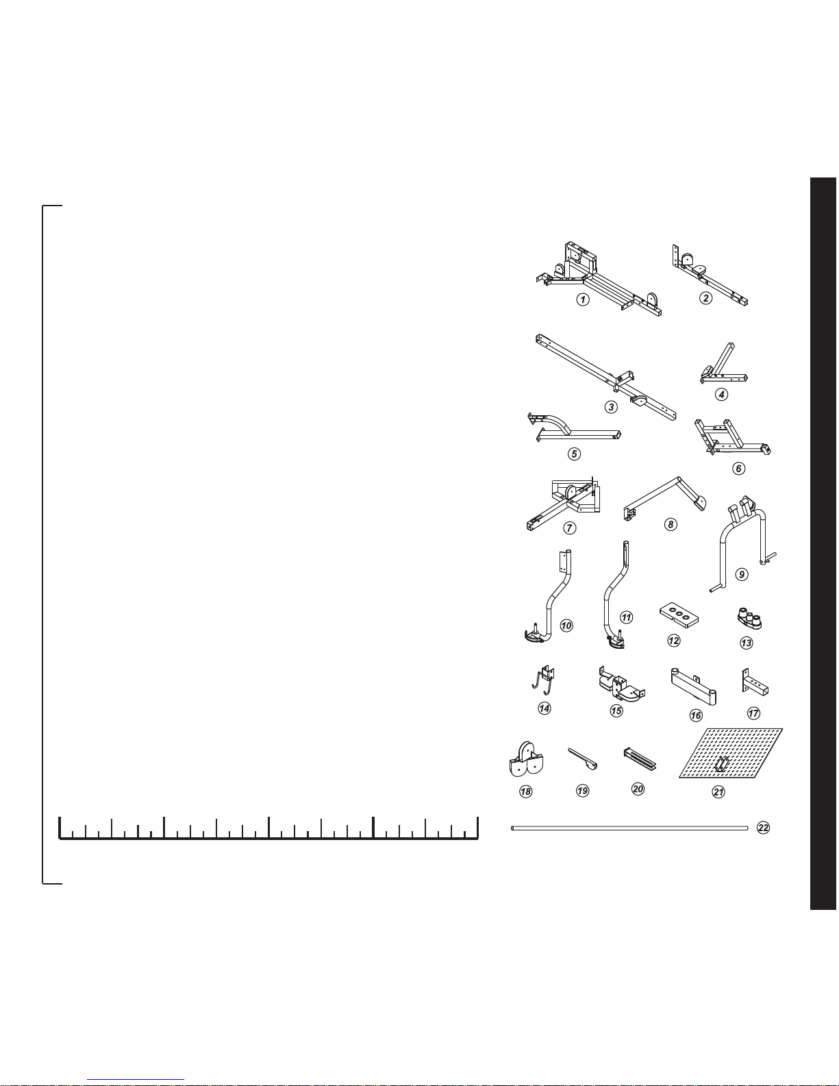
part s list
-3-
DESCRIPTION
BASE FRAME
SIDE BASE
UPRIGHT
SQUAT BASE
SQUAT SUPPORT
PEC DEC BASE
TOP FRAME
SQUAT LEVER
SQUAT ARM
RIGHT PEC DEC ARM
LEFT PEC DEC ARM
WEIGHT PLATE
TOP WEIGHT PLATE
LAT BAR HOLDER
PEC DEC PULLEY BLOCK
PEC DEC SUPPORT
ADJ BACK
THREE-PULLEY BLOCK
ADJUSTER LEVER
FLOATING PULLEY BLOCK
FOOT PLATE
GUIDE ROD
NUMBER
1
2
3
4
5
6
7
8
9
10
11
12
13
14
15
16
17
18
19
20
21
22
QUANTITY
1
1
1
1
1
1
1
1
1
1
1
19
1
1
1
1
1
1
1
2
1
2
A MAJORITY OF THE LISTED HARDWARE IS ALREADY IN PLACE
0 1” 2” 3” 4”
1/2
3/41/4
1/2
3/41/4
1/2
3/41/4
1/2
3/41/4
INCHES
5”
1/2
3/41/4
6”
1/2
3/41/4
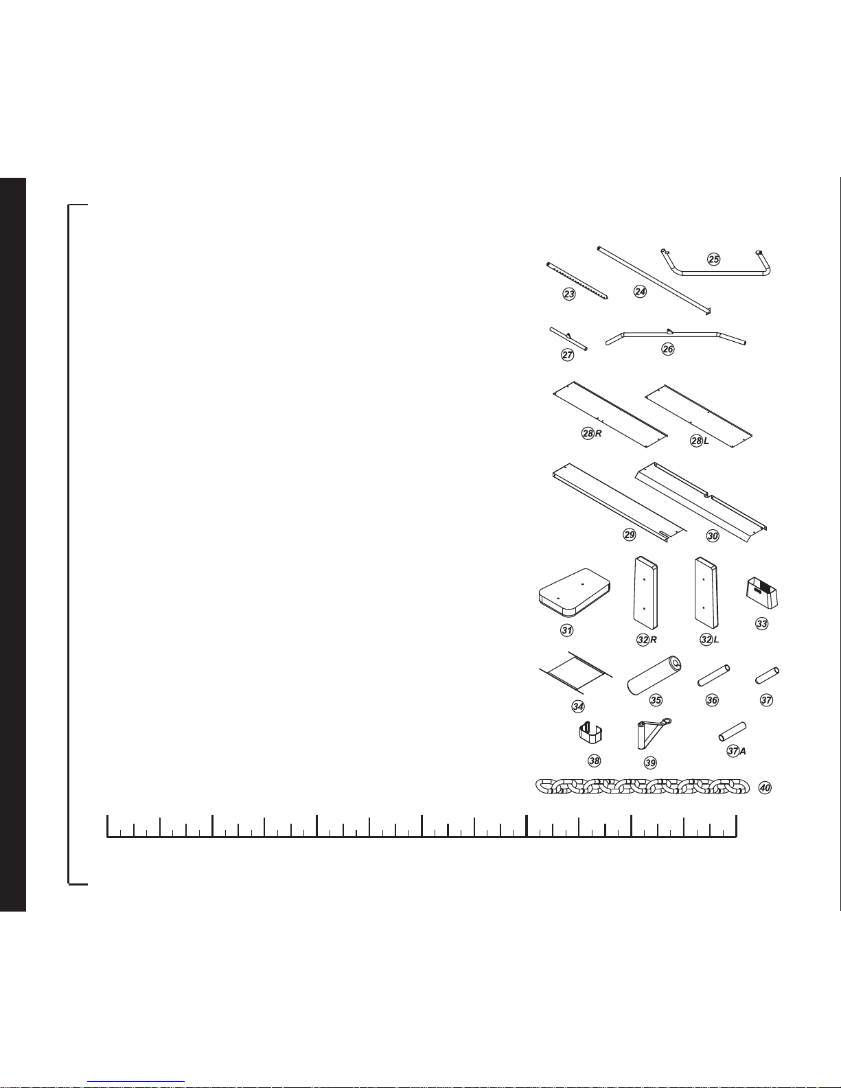
part s list
-4-
ORDER NUMBER
50551-23
50551-24
50551-25
50551-26
50551-27
50551-28R
50551-28L
50551-29
50551-30
50551-31
50551-32R
50551-32L
50551-33
50551-34
50551-35
50551-36
50551-37
50551-37A
50551-38
50551-39
50551-40
DESCRIPTION
SELECT ROD
SQUAT AXLE
SQUAT
LAT BAR
CURL BAR
REAR-RIGHT GUARD
REAR-LEFT GUARD
RIGHT GUARD
LEFT GUARD
SEAT / BACK PAD
RIGHT ELBOW PAD
LEFT ELBOW PAD
BAND
FOAM BINDER
SQUAT FOAM PAD
1" X 8" HAND GRIP
1" X 5-1/2" HAND GRIP
1" FOAM TUBE
ANKLE STRAP
SINGLE HANDLE
LINK CHAIN
NUMBER
23
24
25
26
27
28R
28L
29
30
31
32R
32L
33
34
35
36
37
37A
38
39
40
QUANTITY
1
1
1
1
1
1
1
1
1
2
1
1
1
1
1
2
2
2
1
1
1
A MAJORITY OF THE LISTED HARDWARE IS ALREADY IN PLACE
ORDER NUMBER
50551-41
50551-42
50551-43
50551-44
50551-45
50551-46
50551-47
50551-48
50551-49
50551-50
50551-51
50551-52
50551-53
50551-54
50551-55
50551-56
50551-57
50551-58
50551-59
50551-60
50551-61
50551-62
50551-63
50551-64
50551-65
50551-66
50551-67
50551-68
50551-69
50551-70
50551-71
1” 2” 3” 4”0
1/2
3/41/4
1/2
3/41/4
1/2
3/41/4
1/2
3/41/4
INCHES
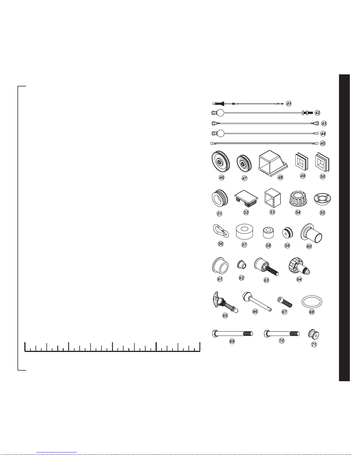
part s list
-5-
DESCRIPTION
ADJ CABLE
TOP CABLE
PEC DEC CABLE
LOWER CABLE
CONNECT CABLE
4-3/8" PULLEY
3-1/2" PULLEY
2" SQ END CAP
1-3/4" SQ END PLUG
2" SQ END PLUG
2" ROUND END PLUG
2" X 3" RECT END CAP
1-1/2" END CAP
STEEL BUSHING (LARGER)
CAP FOR NUT
HOOKUP
RUBBER DOUGHNUT
STOPPER
1-1/4" ROUND PLUG
1" PLASTIC BUSHING
1" STEEL BUSHING (SMALL)
3/8" X 5/8" BUSHING
ADJ STOPPER
QUICK RELEASE
POP PIN
SELECT PIN
TOP PLATE BOLT
RUBBER RING
1/2" X 5" HEX HEAD BOLT
1/2" X 4-1/4" HEX HEAD BOLT
1/2" X 3-1/8" HEX HEAD BOLT
NUMBER
41
42
43
44
45
46
47
48
49
50
51
52
53
54
55
56
57
58
59
60
61
62
63
64
65
66
67
68
69
70
71
QUANTITY
1
1
1
1
1
20
3
3
3
4
4
4
1
6
3
3
2
2
1
4
4
10
1
1
1
1
1
2
2
2
16
A MAJORITY OF THE LISTED HARDWARE IS ALREADY IN PLACE
0 1” 2” 3” 4”
1/2
3/41/4
1/2
3/41/4
1/2
3/41/4
1/2
3/41/4
INCHES
5”
1/2
3/41/4
6”
1/2
3/41/4
part s list
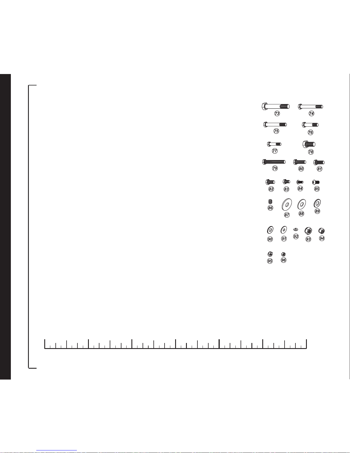
-6-
ORDER NUMBER
50551-73
50551-74
50551-75
50551-76
50551-77
50551-78
50551-79
50551-80
50551-81
50551-82
50551-83
50551-84
50551-85
50551-86
50551-87
50551-88
50551-89
50551-90
50551-91
50551-92
50551-93
50551-94
50551-95
50551-96
DESCRIPTION
SMALL PULLEY
3/8" X 3" HEX HEAD BOLT
3/8" X 2-3/4" HEX HEAD BOLT
3/8" X 1-3/4" HEX HEAD BOLT
5/16" X 1-1/2" HEX HEAD BOLT
1/2" X 3/4" HEX HEAD BOLT (ALL THREADED)
3/8" X 2-3/4" HEX HEAD BOL T (ALL THREADED)
3/8" X 1-1/4" HEX HEAD BOL T (ALL THREADED)
3/8" X 1" HEX HEAD BOLT (ALL THREADED)
3/8" X 3/4" HEX HEAD BOLT (ALL THREADED)
5/16" X 1/2" HEX HEAD BOL T (ALL THREADED)
1/4" X 5/8" ROUND HEAD SCREW
5/16" X 1/2” INNER HEX HEAD BOLT
5/16" X 5/8" SET SCREW
1/2" X 1-1/2" WASHER
1/2" X 1-1/4" WASHER
1/2" X 1 WASHER
3/8" X 7/8" WASHER
5/16" X 7/8" WASHER
"C" WASHER
1/2" NYLON NUT
3/8" NYLON NUT
5/16" NYLON NUT
1/4" NYLON NUT
NUMBER
73
74
75
76
77
78
79
80
81
82
83
84
85
86
87
88
89
90
91
92
93
94
95
96
QUANTITY
1
4
5
18
1
1
2
2
6
3
17
2
2
1
1
2
43
29
20
1
25
29
4
2
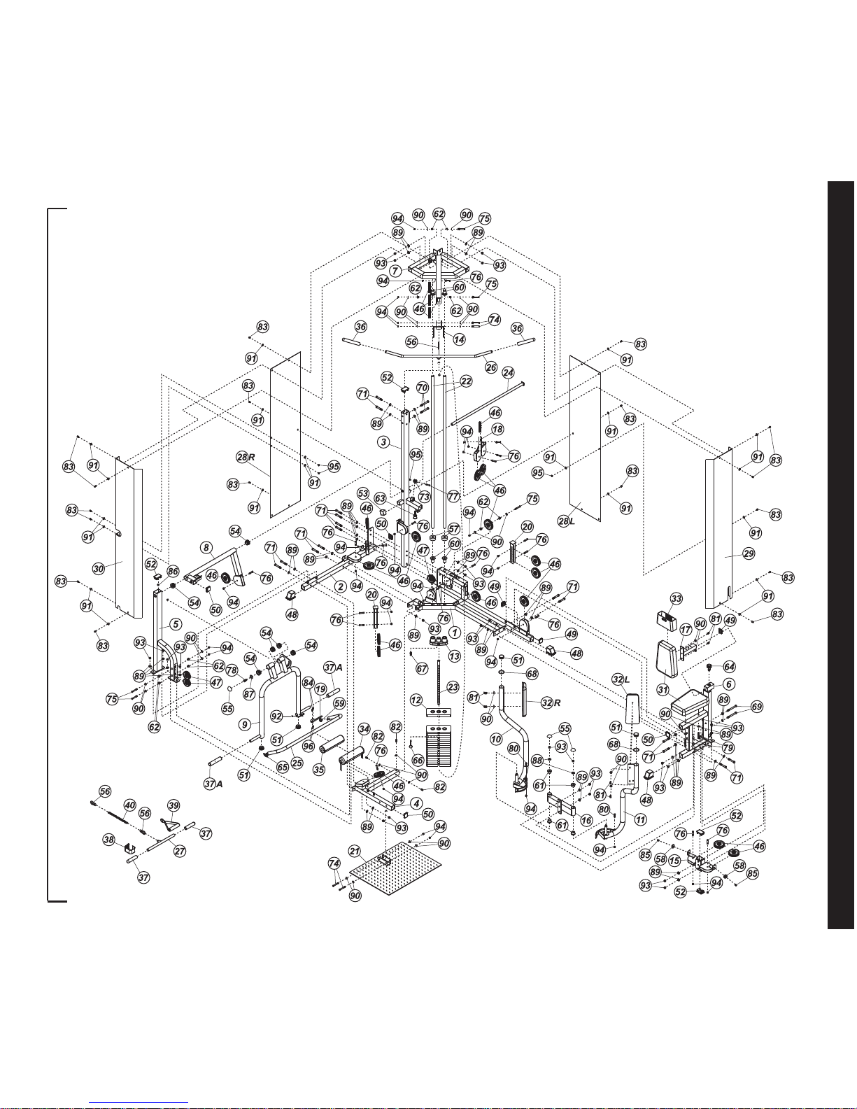
part s diagram
MANY P ARTS SHOWN HAVE BEEN PRE-ASSEMBLED BY THE F ACTOR Y
-7-
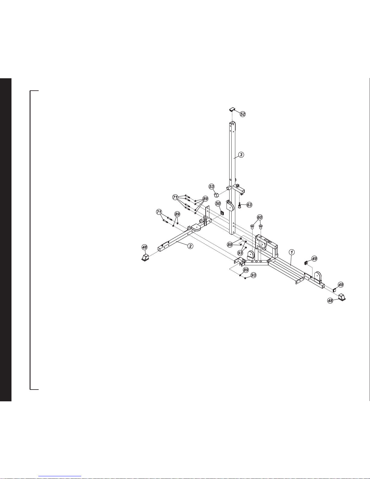
Step 1:
Only hand tighten fasteners for
now. You will be prompted to fully
tighten all fasteners later.
Place the Base Frame (1) on the floor.
Cap the Base Frame (1) with one 2"
Sq End Cap (48) and two 1-3/4" Sq
End Plugs (49). Insert two 1" Plastic
Bushings (60) into the holes in the
Base Frame (1).
Cap the Side Base (2) with one 2" Sq
End Cap (48) and one 2" Sq End Plug
(50).
Cap the Upright (3) with one 1-1/2"
End Cap (53) and one 2" x 3" Rect
End Plug (52). Attach the Adj Stopper
(63) to the Upright (3).
Attach the Side Base (2) and Upright
(3) to the Base Frame (1) using four
1/2" x 3-1/8" Hex Head Bolts (71), six
1/2" Washers (89) and two 1/2" Nylon
Nuts (93). Attach the Side Base (2)
to the Base Frame (1) using two 1/2"
x 3-1/8" Hex Head Bolts (7), three
1/2" Washers (89) and one 1/2" Nylon
Nut (93).
assembly instructions
-8-
ASSEMBLY
assembly instructions
-9-
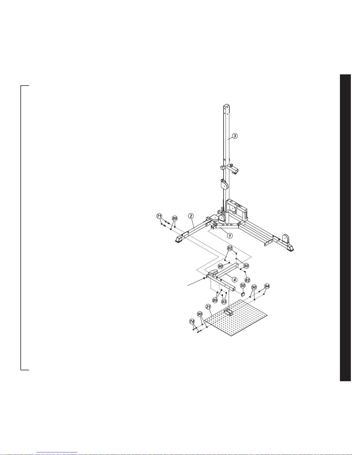
Step 2:
Cap the Squat Base (4) with one 2" Sq
End Plug (50). Attach the Squat Base
(4) to the Base Frame (1) using three
3/8" x 3/4" Hex Head Bolts (82) and
three 3/8" Washers (90). Align the
mounting holes in the link plate (welded
on the Squat Base (4)) with the holes
in the Side Base (2) then attach using
two 1/2" x 3-1/8" Hex Head Bolts (71),
four 1/2" Washers (89) and two 1/2"
Nylon Nuts (93).
Attach the Foot Plate (21) to the Squat
Base (4) using two 3/8" x 3" Hex Head
Bolts (74), four 3/8" Washers (90) and
two 3/8" Nylon Nuts (94).
ASSEMBLY
LINK PLATE
assembly instructions
-10-
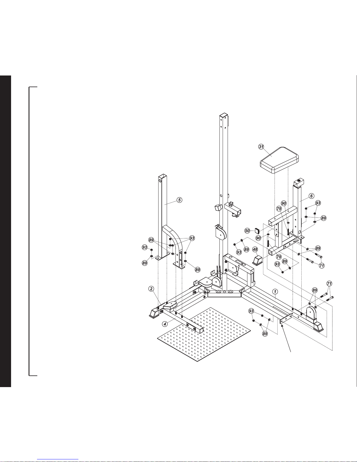
Step 3:
Attach the Squat Support (5) to the Side
Base (2) and Squat Base (4) using two
1/2" Washers (89) and two 1/2" Nylon
Nuts (93) for each.
Cap the Pec Dec Base (6) with one 2"
Sq End Plug (50) and one 2" Sq End
Cap (48). Attach the Pec Dec Base (6)
to the Base Frame (1) using two 1/2" x
3-1/8" Hex Head Bolts (71), six 1/2"
Washers (89) and four 1/2" Nylon Nuts
(93). Align the mounting holes in the
link plate (welded on Base Frame (1))
with the holes in the Pec Dec Base (6)
then attach with two 1/2" x 3-1/8" Hex
Head Bolts (71), four 1/2" Washers (89)
and two 1/2" Nylon Nuts (93).
Attach the Seat / Back Pad (31) to the
Pec Dec Base (6) using two 3/8" x 23/4" Hex Head Bolts (79) and two 3/8"
Washers (90).
ASSEMBLY
LINK PLATE
 Loading...