

Evo H12, H16, H19, H22 Installation & Servicing Instructions Manual
Advanced High Efficiency Boilers
Installation & Servicing Instructions
See reverse for evo HE Users Guide
Manufactured exclusively for Wolseley Centers Ltd. by Ideal Boilers
For details of document amendments, refer to page 3
H12, H16, H19, H22
(V3 Flue System)
Wall mounted, balanced flue, fanned gas boiler
Packaged Boiler Contents have been
checked by Operator Number.......
October 2009 UIN 203323 A05

2
evo HE H - Installation & Servicing

DOCUMENT AMENDMENTS
Relevant Installation changes implemented in this book from Mod Level .............A04 (Apr 08) to A05 (Oct 09)
Page 4, Table 2 - Performance Data
• New SEDBUK figure for H12 boiler.
Page 7, Optional Extra Kits
• Addition of Concentric flue Screw Retaining Kit & Adjustable Flue Support Bracket
Page 16, Frame 12 - Determining the Flue Lengths and Packs Required
• New flue kit added.
• Notes - Item 4 added.
• Note added at bottom of page ref. support bracket
Page 18, Frame 18 - Terminal Wall Seal Assembly / Position
• New frame added ref. positioning of terminal wall seal
Page 19, Frame 21 - Flue Extension Ducts
• Item no. 3 added.
Page 20, Frame 24 - Condensate Pipe Termination Configurations
• Update drawing 1 and note added ref BS6798
Page 29, Frame 37 - Pictorial Wiring Diagram
• Updated drawing showing removal of bracket from spark generator
Page 42, Frame 65 - Combustion Chamber Insulation Replacement
• Updated Frame to reflect new insulation.
Page 48, Frame 76 - H9/L9 Heat Exchanger Overheat
• New flow chart.
Page 49 - Short Parts List
• New updated parts list
Page 52 - Code of Practice
• New Code of Practice Guidelines added.
Wolseley Centers Ltd. reserve the right to vary specification without notice
evo HE H - Installation & Servicing
3
GENERAL
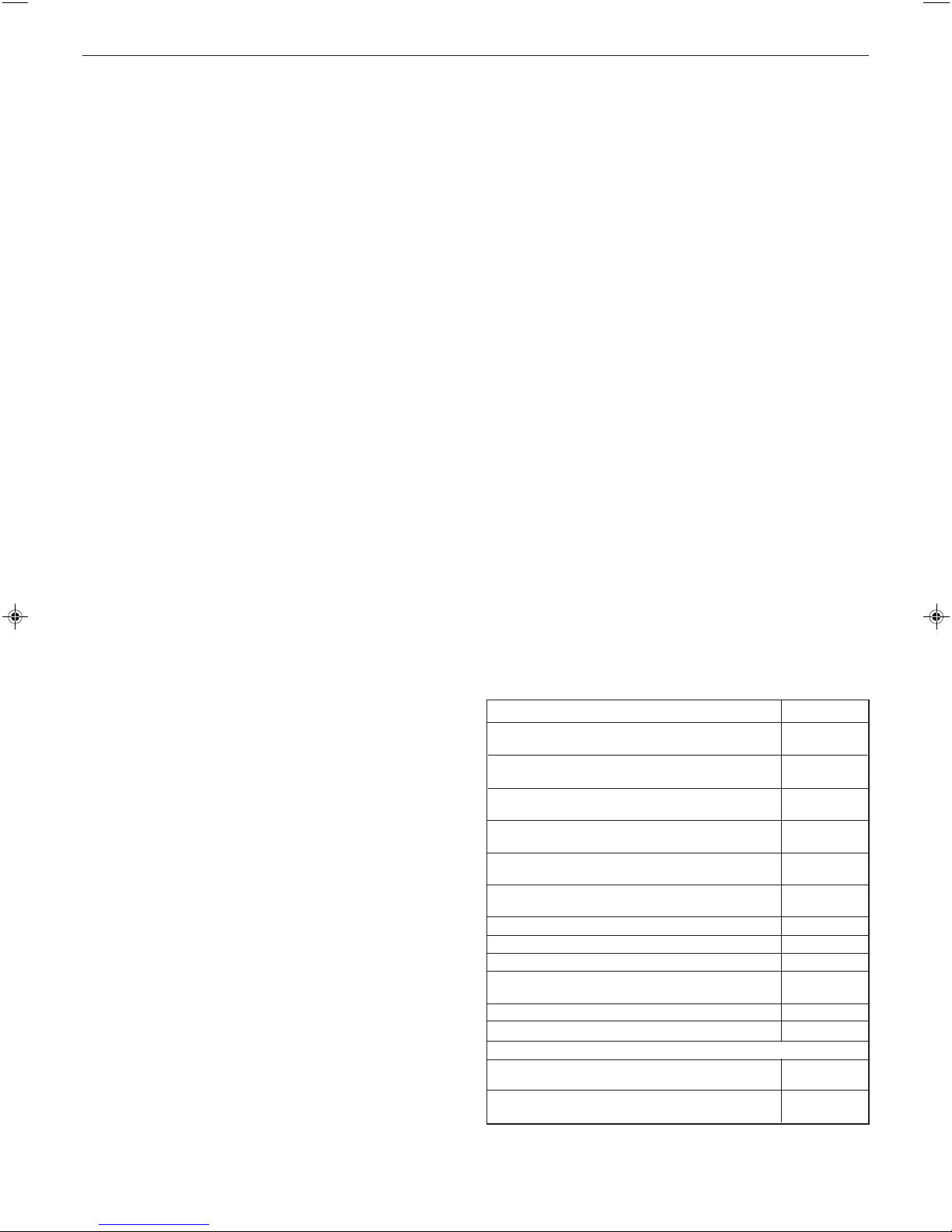
Table 1 - Boiler Data
Boiler Size H12, H16, H19, H22
1
Gas supply type and connection 2H-G20-20 mbar Rc
Injector size Stereomatic 5.6mm dia. (HE 12 5.8mm dia).
Flow connection 22mm copper
Return connection 22mm copper
Flue terminal diameter mm (in.) 100 (4)
Maximum static water head m (ft.) 30.5 (100)
Minimum static water head m (ft.) 0.45 (1.5)
Electrical supply 230 V ~ 50 Hz
Boiler power consumption 38W
Fuse rating External: 3A Internal: T3.15A L250 V
Water content litre (gal.) 1.7 (0.37)
Packaged weight kg (lb.) 38 (84)
Maximum installation weight kg (lb.) 31 (68)
Boiler size Height mm (in.) 582 (23)
Width mm (in.) 390 (15)
Depth mm (in.) 278 (11)
/2 (1/2" BSP Female)
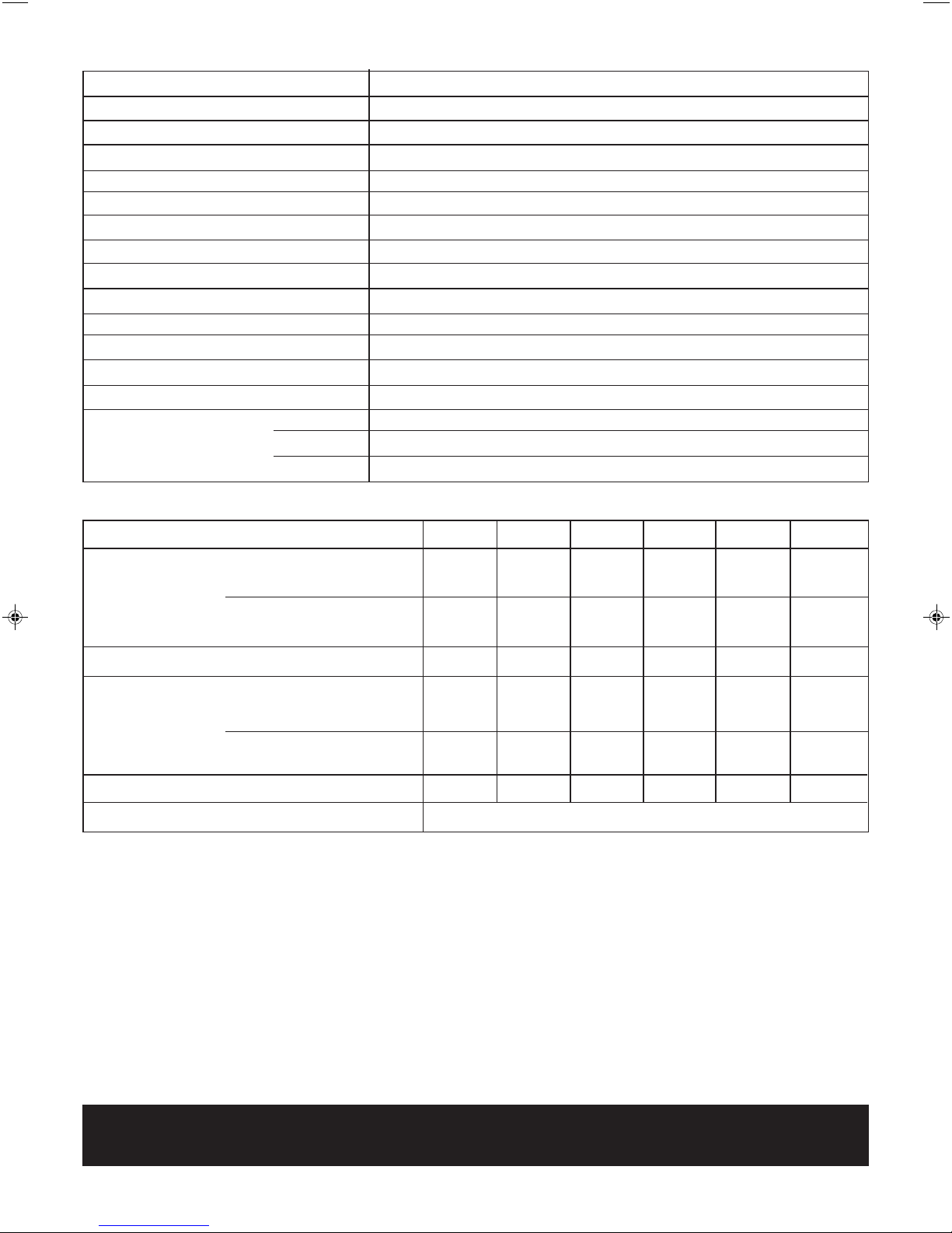
Table 2 - Performance Data
Boiler Size H12 Max H16 Max H19 Max H22 Max H12 min H16-22 Min
Boiler input 'Q' = Nett CV kW 12.2 16.4 19.5 22.6 9.8 9.1
Btu/h 41,600 56,000 66,500 77,100 33,400 31,000
Gross CV kW 13.5 18.2 21.6 25.1 10.9 10.1
Btu/h 46,000 62,100 73,800 85,600 37,200 34,400
Gas consumption l/s (cu.ft/h) 0.35 (44.2) 0.47 (59.9) 0.56 (71.1) 0.65 (82.5) 0.28 (35.6) 0.26 (33.3)
o
Boiler output 'P' = 70
C Mean water kW 12.0 16.1 19.0 22.0 9.3 8.8
temperature Btu/h 40,900 55,000 65,000 75,000 31,800 30,000
o
C Mean water kW 12.7 16.8 20.0 23.3 10.5 9.6
40
temperature Btu/h 43,300 57,400 68,300 79,500 35,900 32,800
Seasonal efficiency (SEDBUK) * Band A [90.3 ]% [90.4 ]% [90.3]% [9 0.2]%
NOx classification Class 5
* The value is used in the UK Government's Standard Assessment Procedure (SAP) for energy rating of dwellings.
The test data from which it has been calculated have been certified by a notified body.
Key to symbols
Note.
Gas consumption is calculated using a calorific value of
38.7 MJ/m3 (1038 Btu/ft3) gross or 34.9 MJ/m3 (935 Btu/ft3)
nett. To obtain the gas consumption at a different calorific
value:-
a. For l/s - divide the gross heat input (kW) by the gross
C.V. of the gas (MJ/m
3
)
b. For ft3/h - divide the gross heat input (Btu/h) by the
gross C.V. of the gas (Btu/ft3)
GB = United Kingdom IE = Ireland (Countries of destination)
PMS = Maximum operating pressure of water
C
13 C33 C53
= A room sealed appliance designed for connection via
ducts to a horizontal or vertical terminal which admits
fresh air to the burner and discharges the products of
combustion to the outside through orifices which, in this
case, are concentric. The fan is up stream of the
combustion chamber.
I
= An appliance designed for use on 2nd Family gas, Group
2H
H only.
CAUTION.
To avoid the possibility of injury during the installation, servicing or cleaning
of this appliance, care should be taken when handling edges of sheet steel components.
4
evo HE H - Installation & Servicing
GENERAL
evo HE
Natural Gas only
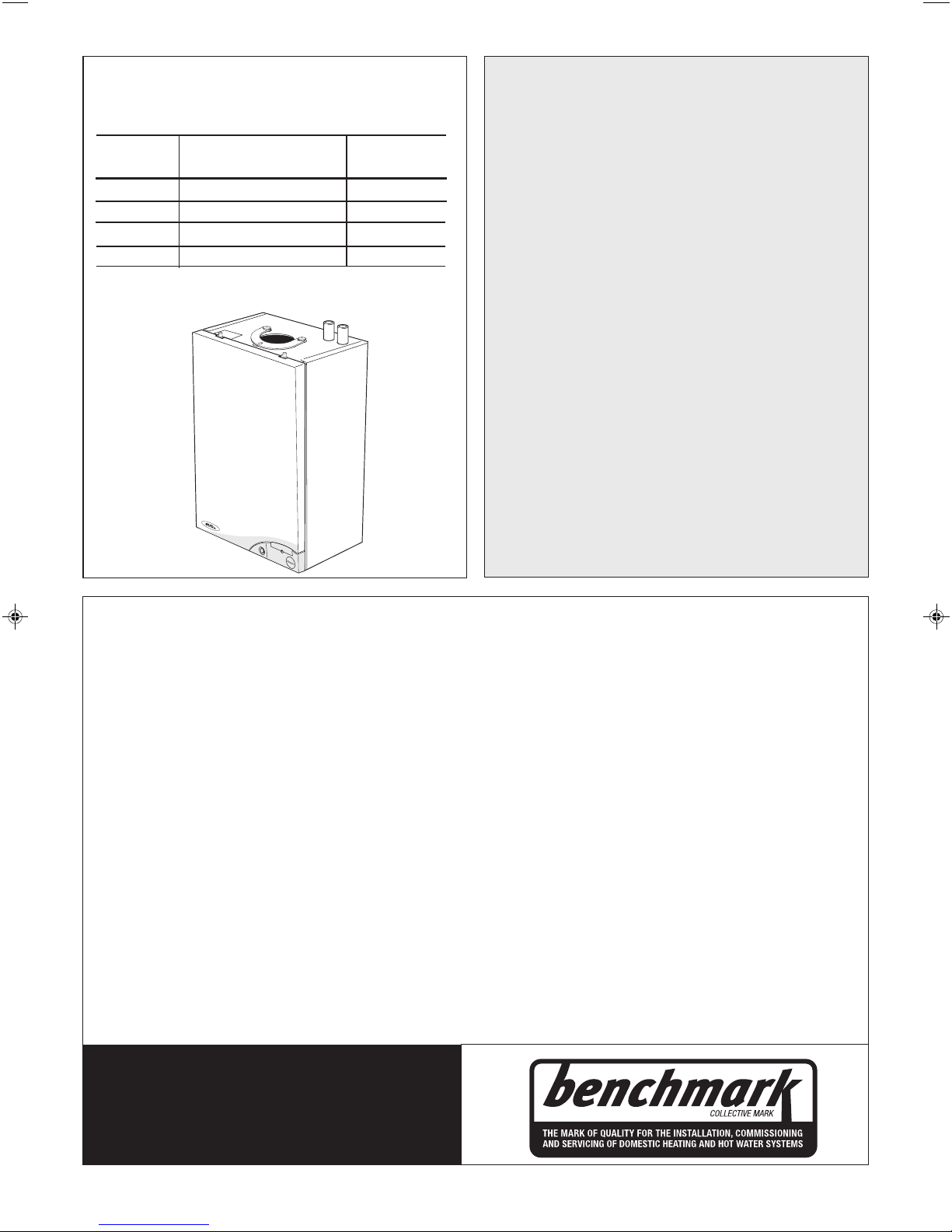
Boiler size G.C. Appliance No. PI No.
(Benchmark No.)
H12 41 397 96 87 BP 34
H16 41 397 86 87 BP 34
H19 41 397 93 87 BP 34
H22 41 397 94 87 BP 34
Destination Countries: GB, IE
CONTENTS
Air Supply ....................................................................... 9
Benchmark Commissioning Checklist ..................... 58
Boiler Clearances ......................................................... 6
Boiler Exploded Diagram ............................................ 14
Electrical Connections ............................................... 29
Electrical Supply ........................................................... 9
Electrical Systems Diagrams .................................... 31
Extension Ducts - Fitting ............................................. 21
Fault Finding ................................................................. 47
Flow Wiring Diagram .................................................. 31
Flue Fitting .............................................................. 17-21
Flue Installation Requirements .................................... 8
Gas Safety Regulations ................................................ 7
Gas Supply ..................................................................... 8
Initial Lighting .............................................................. 33
Installation ............................................................. 14-34
Mandatory Requirements .............................................7
Safe Handling ................................................................ 7
Servicing ................................................................ 35-46
Short List of Parts ....................................................... 51
Terminal Guards ............................................................ 9
Thermostatic Radiator valves .................................... 9
Water and Systems .............................................. 10-13
Water Connections ..................................................... 29
Water Treatment ......................................................... 13
Wiring Diagrams ......................................................... 31
For GB, to comply with Building Regulations Part L1 (Part 6 in Scotland) the boiler should be fitted in accordance with the
manufacturer's instructions. Self-certification that the boiler has been installed to comply with Building Regulations can be
demonstrated by completing and signing the Benchmark Commissioning Checklist.
Before installing this boiler, read the Code of Practice Sheet at the rear of this book.
BENCHMARK COMMISSIONING CHECKLIST DETAILS
Boiler Page
Make and model ....................................................... 5
Appliance serial no. on data badge ....... Front Cover
SEDBUK No. % ......................................................... 4
Controls
Time and temperature control to heating ............. 32
Time and temperature control to hot water .......... 32
Heating zone valves .............................................. n/a
TRV's ......................................................................... 9
Auto bypass ..............................................................9
Boiler interlock .......................................................... 9
For all boilers
Flushing to BS.7593 .............................................. 13
Inhibitor .................................................................. 13
Central heating mode
Heat input ................................................to be calculated
Burner operating pressure .................................... n/a
Central heating flow temp. ...... measure and record
Central heating return temp. ... measure and record
For combination boilers only
Scale reducer ......................................................... n/a
Hot water mode
Heat input ............................................................... n/a
Max. operating burner pressure ..............................n/a
Max. operating water pressure .............................n/a
Cold water inlet temp ............................................n/a
Hot water outlet temp. ........................................... n/a
Water flow rate at max. setting ..............................n/a
For condensing boilers only
Condensate drain .................................................. 22
For all boilers: complete, sign & hand over to customer
For assistance see Technical Helpline on the back page
Page
NOTE TO THE INSTALLER:
THE BENCHMARK COMMISSIONING
CHECKLIST AND LEAVE THESE
INSTRUCTIONS WITH APPLIANCE
evo HE H - Installation & Servicing
COMPLETE
5
GENERAL
1
BOILER WATER CONNECTIONS
The boiler flow and return pipes are supplied fitted to the boiler
ready for top connection
Notes.
a. For the heating loads in excess of 60,000 Btu/h, 28mm (1") flow
and return pipes should be used to and from the boiler.
b. This appliance is NOT suitable for use with a direct hot water
cylinder.
2
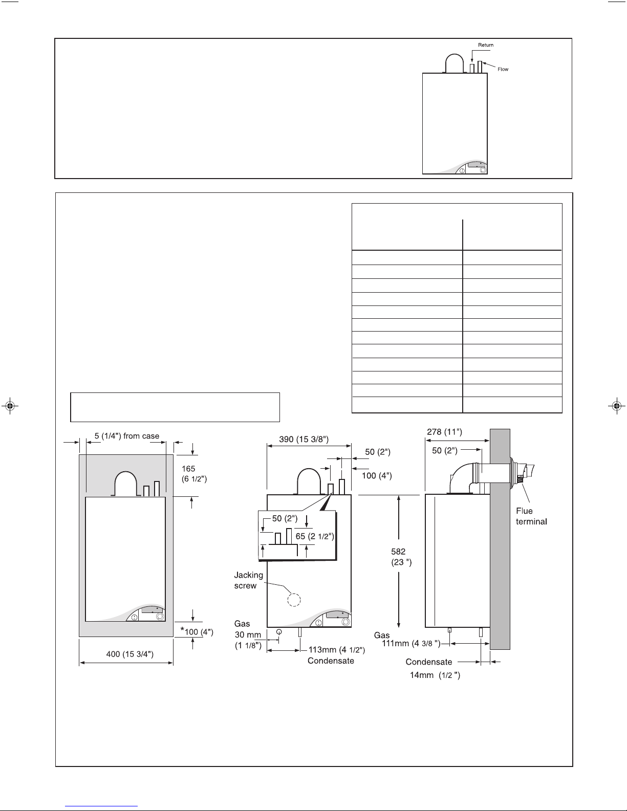
BOILER CLEARANCES all dimensions in mm (in.)
The following minimum clearances must be maintained for
operation and servicing.
Additional space will be required for installation, depending upon
site conditions.
Side and Rear Flue
a Provided that the flue hole is cut accurately, e.g. with a core drill,
the flue can be installed from inside the building where wall
thicknesses do not exceed 600mm (24"). Where the space into
which the boiler is going to be installed is less than the length of
flue required the flue must be fitted from the outside.
Installation from inside ONLY
b. If a core boring tool is to be used inside the building the space in
which the boiler is to be installed must be at least wide enough
to accommodate the tool.
REAR FLUE ONLY
MIN. Top clearance required = 145 mm (5 3/4")
nm7291
SIDE FLUE ONLY
Horizontal length of flue Top clearance
from centre line of boiler required (MIN.)
to outside wall Dim. A
0.5 m 160 mm (6
1.0 m 170 mm (6
1.5 m 185 mm (7 1
2.0 m 200 mm ( 7 7/8")
2.5 m 210 mm (8 1
3.0 m 225 mm (8 7/8")
3.5 m 235 mm (9
4.0 m 250 mm (10 7/8")
4.5 m 260 mm (10
5.0 m 275 mm (10 13/16")
5.5 m 290 mm (11
6.0 m 300 mm (11 13/16")
5/16")
11/16)
/4")
/4")
1/4")
1/4")
3/8")
nm7292
Front clearance
The minimum front clearance when built in to a cupboard
is 5mm (1/4") from the cupboard door but 450mm (17 3/4")
overall clearance is still required, with the cupboard door
open, to allow for servicing.
6
nm8778
* Bottom clearance
after installation can be reduced to 5mm in an adequately
ventilated enclosed cupboard. However, 100mm must be
available for servicing.
evo HE H - Installation & Servicing

GENERAL
INTRODUCTION
The evo HE range of boilers are a fully automatically controlled,
wall mounted, low water content, balanced flue, fanned,
condensing gas boiler. It has full modulating central heating
outputs of :
H12 9.3 kW (32,000 Btu/h) to 12 kW (41,000 Btu/h).
H16 8.8 kW (30,000 Btu/h) to 16.1 kW (55,000 Btu/h).
H19 8.8 kW (30,000 Btu/h) to 19.0 kW (65,000 Btu/h).
H22 8.8 kW (30,000 Btu/h) to 22.0 kW (75,000 Btu/h).
Due to the high efficiency of the boiler a plume of water vapour
will form at the flue terminal during operation depending on
external conditions.
The boiler casing is of white painted mild steel with the user
controls capable of being mounted remotely from the boiler, if
the option is required.
The heat exchanger is of cast aluminium.
Note.
These boilers cannot be used on systems which include gravity
circulation.
The boilers are suitable for connection to fully pumped, open
vented or sealed water systems. Adequate arrangements for
completely draining the system by provision of drain cocks
MUST be provided in the installation pipework.
SAFE HANDLING
This boiler may require 2 or more operatives to move it to its
installation site, remove it from its packaging base and during
movement into its installation location. Manoeuvring the boiler
may include the use of a sack truck and involve lifting, pushing
and pulling.
Caution should be exercised during these operations.
Operatives should be knowledgeable in handling techniques
when performing these tasks and the following precautions
should be considered:
• Grip the boiler at the base.
• Be physically capable.
• Use PPE as appropriate, e.g. gloves, safety footwear.
During all manoeuvres and handling actions, every attempt
should be made to ensure the following unless unavoidable
and/or the weight is light.
• Keep back straight.
• Avoid twisting at the waist.
• Avoid upper body/top heavy bending.
• Always grip with the palm of the hand.
• Use designated hand holds.
• Keep load as close to the body as possible.
• Always use assistance if required.
OPERATION
When there is a demand for heat, the heating system is supplied
at the selected temperature of between 30oC and 82oC.
The boiler features a comprehensive diagnostic system which
gives detailed information on the boiler status when operating,
and performance of key components to aid commissioning and
fault finding.
OPTIONAL EXTRA KITS
• Flue Extension Ducts (1000mm long up to 6m)
• Flue Finishing Kit
o
• 90
Elbow Kit (maximum 4 elbows per installation).
• 45o Elbow Kit (maximum 4 elbows per installation).
• Concentric Flue Screw Retaining Kit
• Roof Flue Kit (to a maximum of 7.5m)
• Powered Vertical Flue Kit 5m primary and 17m secondary is
a typical maximum length. For alternative maximum lengths
refer to Powered Vertical Instructions.
• High Level Flue Outlet Kits
• Flue Deflector Kit
• Weather Collar
• Horizontal Flue Terminal 600mm long.
• Remote User Control Kit
• Boiler Stand-off Kit
• Siphon Kit
• Condensate Pump Kit
• Adjustable Flue Support Bracket
SAFETY
Current Gas Safety (Installation and Use) Regulations or
rules in force.
The appliance is suitable only for installation in GB and IE and
should be installed in accordance with the rules in force.
In GB, the installation must be carried out by a Gas Safe
Registered Engineer. It must be carried out in accordance with
the relevant requirements of the:
• Gas Safety (Installation and Use) Regulations
• The appropriate Building Regulations either The Building
Regulations, The Building Regulations (Scotland), Building
Regulations (northern Ireland).
• The Water Fittings Regulations or Water byelaws in
Scotland.
• The Current I.E.E. Wiring Regulations.
Where no specific instructions are given, reference should be
made to the relevant British Standard Code of Practice.
In IE, the installation must be carried out by a Registered Gas
Installer (RGII) and installed in accordance with the current
edition of I.S.813 "Domestic Gas Installations", the current
Building Regulations and reference should be made to the
current ETCI rules for electrical installation.
Detailed recommendations are contained in the following British
Standard Codes of Practice:
BS. 5440:1 Flues (for gas appliances of rated input not
exceeding 70 kW).
BS. 5440:2 Ventilation (for gas appliances of rated input not
exceeding 70 kW).
BS. 5449 Forced circulation hot water systems.
BS. 5546 Installation of gas hot water supplies for
domestic purposes (2nd Family Gases).
BS. 6798 Installation of gas fired hot water boilers of rated
input not exceeding 60 kW.
BS. 6891 Low pressure installation pipes.
Health & Safety Document No. 635
The Electricity at Work Regulations, 1989.
The manufacturer’s notes must NOT be taken, in any way, as
overriding statutory obligations.
IMPORTANT. These appliances are CE certificated for safety
and performance. It is, therefore, important that no external
control devices, e.g. flue dampers, economisers etc., are
directly connected to these appliances unless covered by these
Installation and Servicing Instructions or as otherwise
recommended by Wolseley Centers Ltd. in writing. If in doubt
please enquire.
Any direct connection of a control device not approved by
Wolseley Centers Ltd. may invalidate the certification and the
normal appliance warranty. It could also infringe the Gas Safety
Regulations and the above regulations.
evo HE H - Installation & Servicing
7
GENERAL
SAFE HANDLING OF SUBSTANCES
Care should be taken when handling the boiler insulation
panels, which can cause irritation to the skin. No asbestos,
mercury or CFCs are included in any part of the boiler or its
manufacture.
LOCATION OF BOILER
The boiler must be installed on a flat and vertical wall, capable
of adequately supporting the weight of the boiler and any
ancillary equipment.
The boiler may be fitted on a combustible wall and insulation
between the wall and the boiler is not necessary, unless
required by the local authority.
For electrical safety reasons there must be no access from the
back of the boiler.
The boiler must not be fitted outside.
Timber Framed Buildings
If the boiler is to be fitted in a timber framed building it should
be fitted in accordance with the Institute of Gas Engineering
document IGE/UP/7:1998.
Bathroom Installations
This appliance is rated IP20.
The boiler may be installed in any room or internal space,
although particular attention is drawn to the requirements of the
current IEE (BS.7671) Wiring Regulations and, in Scotland, the
electrical provisions of the building regulations applicable in
Scotland, with respect to the installation of the boiler in a room
or internal space containing a bath or shower. For Ireland
reference should be made to the current ETCI rules for
electrical installations and I.S.813:2002.
If the appliance is to be installed in a room containing a bath or
shower then, providing water jets are not going to be used for
cleaning purposes (as in communal baths/showers), the
appliance must be installed in Zone 2, as detailed in BS.7671.
Compartment Installations
A compartment used to enclose the boiler should be designed
and constructed specially for this purpose.
An existing cupboard or compartment may be used, provided
that it is modified for the purpose.
In both cases details of essential features of cupboard /
compartment design, including airing cupboard installation,
are to conform to the following:
z BS. 6798. (No cupboard ventilation is required - see “Air
Supply” for details).
z The position selected for installation MUST allow adequate
space for servicing in front of the boiler.
z For the minimum clearances required for safety and
subsequent service see the wall mounting template and
Frame 2. In addition, sufficient space may be required to
allow lifting access to the wall mounting plate.
GAS SUPPLY
The local gas supplier should be consulted, at the installation
planning stage, in order to establish the availability of an
adequate supply of gas. An existing service pipe must NOT be
used without prior consultation with the local gas supplier.
The boiler MUST be installed on a gas supply with a governed
meter only.
A gas meter can only be connected by the local gas supplier or
by a Gas Safe Registered Engineer. In IE by a Registered Gas
Installer (RGII).
An existing meter should be checked, preferably by the gas
supplier, to ensure that the meter is adequate to deal with the
rate of gas supply required.
It is the responsibility of the Gas Installer to size the gas
installation pipework in accordance with BS6891:2005. Whilst
the principle of the 1:1 gas valve ensures the evo H range is
8
able to deliver it’s full output at inlet pressures as low as 14mb,
other gas appliances in the property may not be as tolerant.
When operating pressures are found to be below the minimum
meter outlet of 19mb these should be checked to ensure this is
adequate for correct and safe operation.
Allowing for the acceptable pressure loss of 1mb across the
installation pipework, it can be assumed that a minimum
permitted operating pressure of 18mb will be delivered to the
inlet of the appliance. (Reference BS 6400-1 Clause 6.2
Pressure Absorption).
The integral appliance isolation valve and boiler pipework could
further reduce the operating pressure by up to 1.5mb when
measured at the inlet test point on the appliance gas valve.
Therefore it has been identified that an operating pressure as
low as 16.5mbar could be measured at the appliance inlet
pressure test point on the gas valve.
IMPORTANT.
Installation pipes MUST be fitted in accordance with BS. 6891.
In IE refer to I.S.813:2002. Pipework from the meter to the boiler
MUST be of an adequate size.
The complete installation MUST be tested for gas tightness and
purged as described in the above code.
FLUE INSTALLATION
Pluming will occur at the terminal so terminal positions which
would cause a nuisance should be avoided.
The flue must be installed in accordance with the
recommendations of BS.5440-1:2000. In IE refer to I.S.813:2002.
The following notes are intended for general guidance.
1. The boiler MUST be installed so that the terminal is exposed
to external air.
2. It is important that the position of the terminal allows the free
passage of air across it at all times.
3. Minimum acceptable spacing from the terminal to obstructions
and ventilation openings are specified in Table 3.
Table 3 - Balanced Flue Terminal Position
Flue Terminal Positions
1. Directly below, above or alongside an opening
window, air vent or other ventilation opening. 300m m (1 2" )
2. Below guttering, drain pipes or soil pipes. 25mm ( 1")*
BS5440-1 2000 75mm (3")
3. Below eaves. 25mm (1")*
BS5440-1 2000 200mm (8")
4. Below balconies or a car port roof. 25mm (1")*
BS5440-1 2000 200mm (8")
5. From vertical drain pipes or soil pipes. 25mm (1")*
BS5440-1 2000 150mm (6")
6. From an internal or external corner or to a 25mm (1")*
boundary along side the terminal. BS5440-1 2000 300mm (12")
7. Above adjacent ground, roof or balcony level. 300mm (12")
8. From a surface or a boundary facing the terminal. 600mm (24")
9. From a terminal facing a terminal. 1,200mm (48")
10. From an opening in a car port
(e.g. door or window) into dwelling. 1,200mm (48")
11. Vertically from a terminal on the same wall. 1,500mm (60")
12. Horizontally from a terminal on the wall. 300mm (12")
Vertical Terminals
13. Above the roof pitch with roof slope of all angles. 300mm (12")
Above flat roof. 300mm (12")
14. From a single wall face. 300mm (12")
From corner walls. 300mm (12")
* Only one reduction down to 25mm is allowable per installation
otherwise BS5440-1 2000 dimensions must be followed.
Min. Spacing*
evo HE H - Installation & Servicing
GENERAL
4. Where the lowest part of the terminal is fitted less than 2m
(6'6") above a balcony, above ground or above a flat roof to
which people have access, then the terminal MUST be
protected by a purpose designed guard.
Ensure that the guard is fitted centrally.
Terminal guards are available from boiler suppliers. Ask for
TFC Flue Guard Model No. K6 (round plastic-coated). In
case of difficulty contact:
Grasslin (UK) Ltd. Tel. +44(0) 01732 359 888
Tower House, Vale Rise Fax. +44(0) 01732 354 445
Tonbridge. kent TN9 1TB www.ffc.ukco.com
5. The flue assembly shall be so placed or shielded as to
prevent ignition or damage to any part of any building.
6. The air inlet/products outlet duct and the terminal of the
boiler MUST NOT be closer than 25mm (1") to combustible
material. Detailed recommendations on the protection of
combustible material are given in BS.5440-1:2000. In IE
refer to I.S.813:2002.
IMPORTANT.
It is absolutely ESSENTIAL to ensure, in practice, that products
of combustion discharging from the terminal cannot re-enter
the building or any other adjacent building through ventilators,
windows, doors, other sources of natural air infiltration, or
forced ventilation / air conditioning.
If this should occur the appliance MUST be turned OFF,
labelled as 'unsafe' until corrective action can be taken.
TERMINAL
The terminal assembly can be adapted to accommodate
various wall thicknesses. Refer to Frame 14.
AIR SUPPLY
It is NOT necessary to have a purpose-provided air vent in the
room or internal space in which the boiler is installed. Neither
is it necessary to ventilate a cupboard or compartment in which
the boiler is installed, due to the low surface temperatures of
the boiler casing during operation; therefore the requirements
of BS 6798, Clause 12, and BS 5440:2 may be disregarded. In
IE the requirements of I.S.813:2002 may be disregarded.
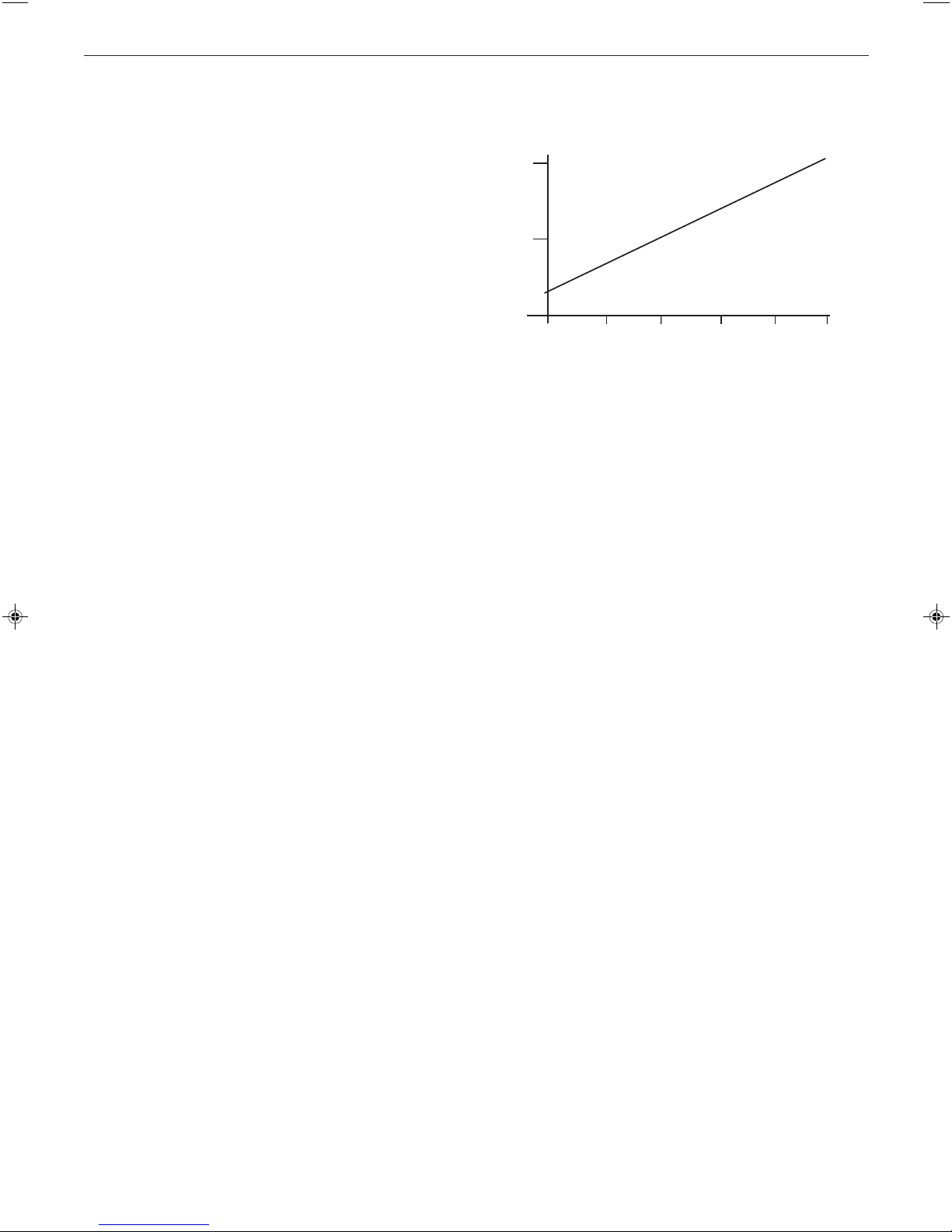
The hydraulic resistance of the boilers, at MAXIMUM OUTPUT,
with an 11
Graph 1.
Graph 1 - Water flow rate and pressure loss
o
C (20 oF) temperature differential, is shown in
1.0
0.5
Pressure Drop Across Boiler
(metres water)
8.8 11.7 14.7 17.6 20.5
Boiler Output (kW)
Ecl 1603
23.4
BOILER CONTROL INTERLOCKS
Wolseley Centers Ltd. recommend that heating systems
utilising full thermostatic radiator valve control of temperature in
individual rooms should also be fitted with a room thermostat
controlling the temperature in a space served by radiators not
fitted with such a valve as stated in BS. 5449.
Central heating systems controls should be installed to ensure
the boiler is switched off when there is no demand for heating
or hot water.
When thermostatic radiator valves are used, the space heating
temperature control over a living / dining area or hallway having
a heating requirement of at least 10% of the boiler heat output
should be achieved using a room thermostat, whilst other
rooms are individually controlled by thermostatic radiator
valves. However, if the system employs thermostatic radiator
valves on all radiators, or two port valves without end switches,
then a bypass circuit must be fitted with an automatic bypass
valve to ensure a flow of water should all valves be in the
closed position.
WATER CIRCULATION SYSTEM
IMPORTANT.
A minimum length of 1 metre of copper pipe MUST be fitted to
both flow and return connections from the boiler before
connection to any plastic piping.
For the types of system and correct piping procedure see
Frames 1, and 3 to 8.
The central heating system should be in accordance with
BS.6798 and, in addition, for smallbore and microbore
systems, BS.5449.
WATER TREATMENT - see Frame 9
The hot water storage cylinder MUST be of the indirect type and
should preferably be manufactured of copper.
Single feed, indirect cylinders are not recommended and MUST
NOT be used on sealed systems.
The appliances are NOT suitable for gravity central heating nor
are they suitable for the provision of gravity domestic hot water.
The hot water cylinder and ancillary pipework, not forming part
of the useful heating surface, should be lagged to prevent heat
loss and any possible freezing - particularly where pipes run
through roof spaces and ventilated underfloor spaces.
The boiler must be vented.
evo HE H - Installation & Servicing
ELECTRICAL SUPPLY
WARNING.
This appliance must be earthed.
Wiring external to the appliance MUST be in accordance with
the current I.E.E. (BS.7671) Wiring Regulations and any local
regulations which apply. For Ireland reference should be made
to the current ETCI rules for electrical installations.
The point of connection to the mains should be readily
accessible and adjacent to the boiler.
NOTE: THE FAN VOLTAGE IS 325V DC
CONDENSATE DRAIN - Refer to Frames 23 & 44
A condensate drain is provided on the boiler. This drain must
be connected to a drainage point. All pipework and fittings in
the condensate drainage system MUST be made of plastic - no
other materials may be used.
IMPORTANT.
Any external runs must be insulated.
The drain outlet on the boiler is standard 21.5mm (3/4”)
overflow pipe.
9

GENERAL
3
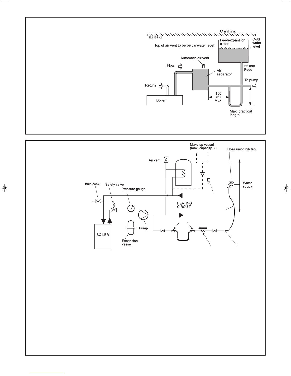
OPEN VENT SYSTEM REQUIREMENTS
The system should be vented directly off the boiler flow pipe, as
close to the boiler as possible. The cold feed entry should be
inverted and MUST be positioned between the pump and the vent,
and not more than 150mm (6") away from the vent connection.
Note. Combined feed and vent pipes may also be fitted.
There should be a minimum height 450mm (18") of open vent
above the cistern water level. If this is not possible refer to
Frame 5. The vertical distance between the highest point of the
system and the feed/expansion cistern water level MUST not be
less than 450 mm (18"). The pump must be fitted on the flow side of
the boiler.
A suitable pump is a domestic circulator capable of providing a
maximum 11
whole of the heating circuit open (e.g. Grundfos UPS 15/50, 15/60 or
equivalent). With the minimum flow circuit allowed by the controls the
differential must not exceed 25 oC. (18oC for the H16)
The vertical distance between the pump and feed/expansion cistern
MUST comply with the pump manufacturer's minimum requirements, to
avoid cavitation. Should these conditions not apply either lower the
pump position or raise the cistern above the minimum requirement
specified by Wolseley Centers Ltd. The isolation valves should be
fitted as close to the pump as possible.
o
C (20oF) temperature differential across the boiler with the
Return & flow
connections
load 30 - 60 = 22 mm
load 70 - 80 = 28 mm
4
SCHEMATIC PIPEWORK AND SYSTEM BALANCING
The boiler does not normally need a bypass but at least some
radiators on the heating circuit, of load at least 10% of the
minimum boiler output, must be provided with twin lockshield
valves so that this minimum heating load is always available
(see footnote re. thermostatic radiator valves).
Balancing
1. Set the programmer to ON for both CH
and HW. Turn the cylinder thermostat
down. Close the manual or thermostatic
valves on all radiators, leaving the twin
lockshield valves (on the radiators
referred to above) in the open position.
Turn up the room thermostat and adjust
these lockshield valves to give boiler flow
and return temperatures not more than
o
C apart. These valves should now be
20
left as set.
2. Open all manual or thermostatic radiator
valves and adjust the lockshield valves
on remaining radiators to give around
o
11
C temperature drop at each radiator.
3. Turn up the cylinder thermostat and
adjust the cylinder balancing valve so
that the cylinder achieves a maximum
flow consistent with adequate flow to the
radiators. Check that with only the
domestic hot water loop in circuit a
differential temperature of 20
the boiler is not exceeded.
4. Adjust room and cylinder thermostats
and programmer to NORMAL settings.
o
C across
10
evo HE H - Installation & Servicing
GENERAL
Non-return
valve
Automatic
air vent
Hose unions
Additional
stop valve
Hose connector
Hosepipe
(disconnect
after filling)
Double check valve
assembly
(note direction of flow)
Temporary hose
(disconnect
after filling)
ecl6060
5
LOW HEAD AND LARGE SYSTEMS WITH EXTENSIVE PIPE RUNS - OPEN VENT
This arrangement is useful for large systems where
radiators at the extremities are difficult to vent. This can
lead to pumping over with conventional feed and vent
arrangements.
The following conditions MUST be observed:
1. The top of the automatic air vent must be below the
cold water level.
2. The static water level (cold) must be at least 200mm
above the top of the horizontal flow pipe, fitted as
shown. The vent connection MUST NOT be made
immediately off the top of the boiler as venting is
made less efficient.
3. The maximum practical length of 22mm cold feed pipe
should be used in order to reduce the effective volume
of hot system water expanding into the feed/expansion
cistern to a minimum.
All dimensions in mm (in.).
Note. The pump manufacturers' minimum requirements must be complied with.
6
SEALED SYSTEM REQUIREMENTS
Notes.
a. The method of filling, refilling, topping up or flushing
sealed primary hot water circuit from the mains via a
temporary hose connection is
only allowed if
acceptable to the
local water authority.
NB. Imperial dimensions are approximate
b. When installing the
filling device, it must be
connected as shown to
fully comply with the
water regulations. This
may involve the fitting of
an additional WRAS
approval isolator valve
to the mains supply.
1. General
a. The installation
must comply with the
requirements of BS. 6798
and BS. 5449.
b. The installation should be designed to work with
flow temperatures of up to 82
o
C.
c. All components of the system, including the heat
exchanger of the indirect cylinder, must be
suitable for a working pressure of 3 bar (45lb/in
and temperature of 110oC. Care should be taken
in making all connections so that the risk of
leakage is minimised.
2. Safety Valve
A spring loaded safety valve complying with the
relevant requirements of BS. 6759 must be fitted in
the flow pipe as close to the boiler as possible and
with no intervening valve or restriction. The valve
should have the following features:
evo HE H - Installation & Servicing
2
)
a. A non-adjustable preset lift pressure not exceeding
3bar (45lb/in
2
).
b. A manual testing device.
c. Provision for connection of a discharge pipe.
The valve or discharge pipe should be positioned so
that the discharge of water or steam cannot create a
hazard to the occupants of the premises or cause
damage to electrical components and wiring.
3. Pressure Gauge
A pressure gauge covering at least the range 0-4 bar
(0-60 lb/in
2
) must be fitted to the system. The gauge
should be easily seen from the filling point and should
preferably be connected at the same point as the
expansion vessel.
11

GENERAL
SEALED SYSTEM REQUIREMENTS - continued
7
4. Expansion Vessel
a. A diaphragm type expansion vessel must be
connected to a point close to the inlet side of the
pump, the connecting pipe being not less than 15 mm
1/2" nominal) size and not incorporating valves of
(
any sort.
b. The vessel capacity must be adequate to accept the
expansion of the system water when heated to
o
110
C (230oF).
c. The charge pressure must not be less than the
static water head above the vessel. The pressure
attained in the system when heated to 110
F) should be at least 0.35 bar (5 Ib/in2) less than the
lift pressure of the safety valve.
For guidance on vessel sizing refer to the table in
Frame 8.
For further details refer to BS. 5449, BS. 7074:1 and
the British Gas Corporation publication 'Material and
Installation Specifications for Domestic Central
Heating and Hot Water'. For IE refer to the current
edition of I.S.813.
5. Cylinder
The cylinder must be either of the indirect coil type or a
direct cylinder fitted with an immersion calorifier which is
suitable for operating on a gauge pressure of 0.35 bar
2
) in excess of the safety valve setting. Single feed
(5 Ib/in
indirect cylinders are not suitable for sealed systems.
6. Make-up Water
Provision must be made for replacing water loss from the
system, either:
a. From a manually filled make-up vessel with a readily
visible water level. The vessel should be mounted at
least 150 mm (6") above the highest point of the
system, and be connected through a non-return valve
to the system, fitted at least 300 mm (12") below the
make-up vessel on the return side of the domestic
hot water cylinder or radiators.
or
b. Where access to a make-up vessel would be difficult
by pre-pressurisation of the system. Refer to 'Filling',
below.
7. Mains Connection
There must be no direct connection to the mains water
supply or to the water storage tank supplying domestic
water, even through a non-return valve, without the
approval of the local water authority.
8. Filling
The system may be filled by one of the following
methods:
a. Through a cistern, used for no other purposes, via a
ball valve permanently connected directly to a service
pipe and/or a cold water distributing pipe.
The static head available from the cistern should be
adequate to provide the desired initial system design
o
C (230
pressure. The cold feed pipe from the cistern should
include a non-return valve and a stop valve with an
automatic air vent connected between them, the stop
valve being located between the system and the
automatic air vent. The stop valve may remain open
during normal operation of the system if automatic
water make-up is required.
b. Through a self-contained unit comprising a cistern,
pressure booster pump (if required) and, if necessary,
an automatic pressure reducing valve and flow
o
restrictor. The cistern should be supplied through a
temporary connection from a service pipe or cold
water distributing pipe.
This unit may remain permanently connected to the
heating system to provide limited automatic water
make-up. Where the temporary connection is supplied
from a service pipe or distributing pipe which also
supplies other draw-off points at a lower level then a
double check valve shall be installed upstream of the
draw-off point.
c. Through a temporary hose connection from a draw-off
tap supplied from a service pipe under mains
pressure. Where the mains pressure is excessive a
pressure reducing valve shall be used to facilitate
filling.
The following fittings shall form a permanent part of
the system and shall be fitted in the order stated:
A stop valve complying with the requirements of
BS. 1010, Part 2 (the hose from the draw-off tap shall
be connected to this fitting).
A test cock.
A double check valve of an approved type.
• Thoroughly flush out the whole of the system with
cold water, without the pump in position.
• With the pump fitted, fill and vent the system until the
pressure gauge registers 1.5 bar (21.5lb/in
2
).
Examine for leaks.
• Check the operation of the safety valve by manually
raising the water pressure until the valve lifts. This
should occur within ± 0.3 bar (± 4.3lb/in
2.
) of the
preset lift pressure.
• Release water from the system until the initial system
design pressure is reached.
• Light the boiler and heat the system to the maximum
working temperature. Examine for leaks.
• Turn off the boiler and drain the system while still hot.
• Refill and vent the system.
• Adjust the initial pressure to the required value.
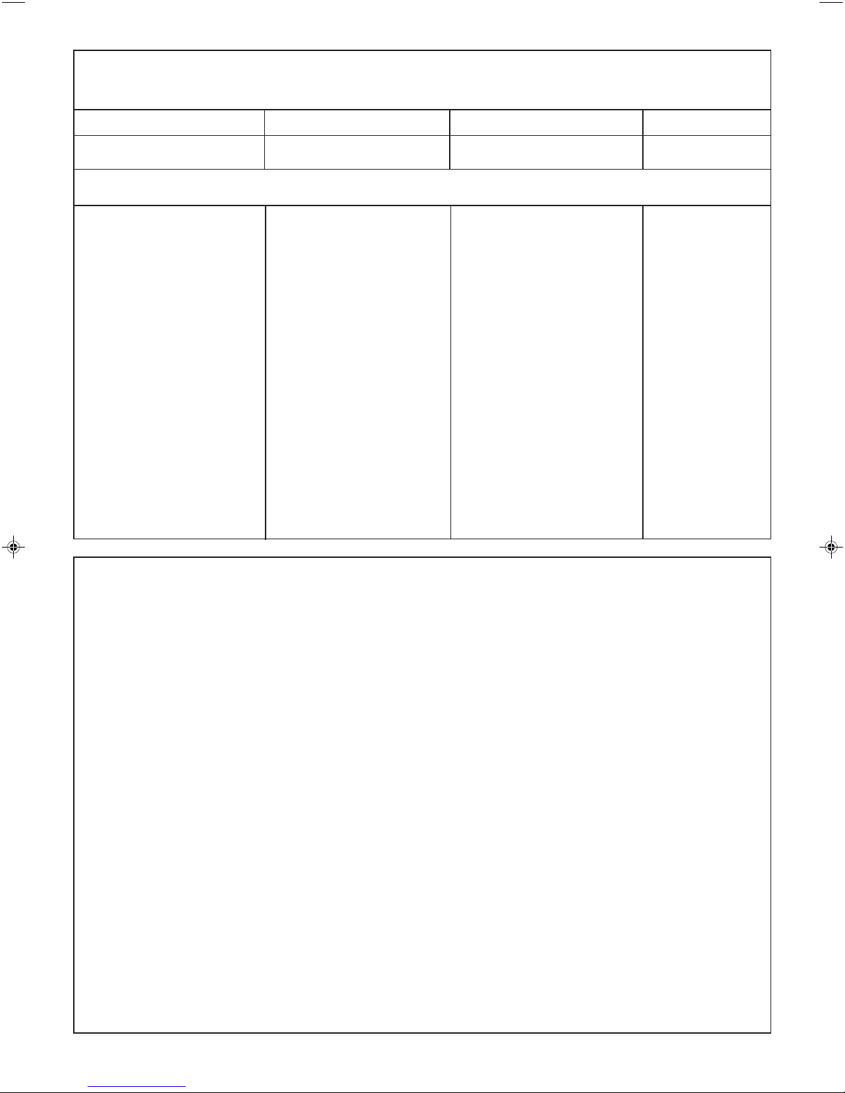
Sizing procedure for expansion vessels: The volume of the expansion vessel (litres) fitted to a sealed system shall not be
less than that given by the table on the following page, multiplied by a factor of 0.8 (for flow temperatures of less than 83
C).
12
o
evo HE H - Installation & Servicing
GENERAL
8
SEALED SYSTEM REQUIREMENTS - continued
Safety valve setting 3.0 bar 2.5 bar 2.0 bar
Vessel charge and initial 0.5 1.0 1.5 0.5 1.0 1.5 0.5 1.0
system pressure bar bar bar bar bar bar bar bar
Total water content of system Expansion vessel volume litres
litres
25 2.1 2.7 3.9 2.3 3.3 5.9 2.8 5.0
50 4.2 5.4 7.8 4.7 6.7 11.8 5.6 10.0
75 6.3 8.2 11.7 7.0 10.0 17.7 8.4 15.0
100 8.3 10.9 15.6 9.4 13.4 23.7 11.3 20.0
125 10.4 13.6 19.5 11.7 16.7 29.6 14.1 25.0
150 12.5 16.3 23.4 14.1 20.1 35.5 16.9 30.0
175 14.6 19.1 27.3 16.4 23.4 41.4 19.7 35.0
200 16.7 21.8 31.2 18.8 26.8 47.4 22.6 40.0
225 18.7 24.5 35.1 21.1 30.1 53.3 25.4 45.0
250 20.8 27.2 39.0 23.5 33.5 59.2 28.2 50.0
275 22.9 30.0 42.9 25.8 36.8 65.1 31.0 55.0
300 25.0 32.7 46.8 28.2 40.2 71.1 33.9 60.0
Multiplying factors for
other system volumes 0.0833 0.109 0.156 0.094 0.134 0.237 0.113 0.20
9
WATER TREATMENT
The evo HE boiler range has an ALUMINIUM alloy heat exchanger
IMPORTANT.
The application of any other treatment to this product may render the guarantee of
Wolseley Centers Ltd. invalid.
Wolseley Centers Ltd.
Treatment in Central Heating systems.
recommend water treatment in accordance with the Benchmark Guidance Notes on Water
Wolseley Centers Ltd. recommend the use of FERNOX-COPAL or MB1 or GE Betz Sentinel X100 inhibitors and
associated water treatment, which must be used in accordance with the manufacturers' instructions. For further
information contact:
Fernox Manufacturing Co. Ltd
Cookson Electronics
Forsyth Road
Sheerwater
Woking
Surrey
GU21 5RZ
Tel: +44 (0) 1799 521133
Notes
1. It is most important that the correct concentration of the water
treatment product is maintained in accordance with the
manufacturers' instructions.
2. If the boiler is installed in an existing system any unsuitable
additives MUST be removed by thorough cleansing.
BS. 7593:2006 details the steps necessary to clean a
domestic central heating system.
Sentinel Performance Solutions
The Heath Business & Technical
Park
Runcorn
Cheshire
WA7 4QX
Tel: 0800 389 4670
www.sentinel-solutions.net
3. In hard water areas, treatment to prevent lime scale
may be necessary - however, the use of artificially
softened water is NOT permitted.
4. Under no circumstances should the boiler be fired
before the system has been thoroughly flushed.
Salamander Engineering Ltd
The Heath Business & Technical
Park
Runcorn
Cheshire
WA7 4QX
Tel: +44 (0) 121 3780952
evo HE H - Installation & Servicing
13
nm8779b
40
94
40
10
INSTALLATION
INSTALLATION
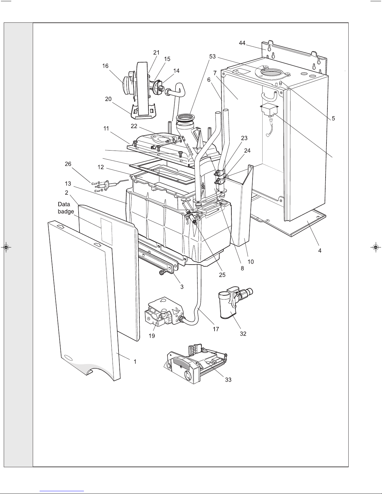
BOILER ASSEMBLY - Exploded view
LEGEND
1. Front casing panel.
2. Sealing panel.
3. Sump cover plate.
4. Bottom casing panel.
5. Flue sensing nipple.
6. Return pipe.
7. Flow pipe.
8. Flue manifold.
10. Interpanel.
11. Burner assy.
12. Combustion chamber
Insulation.
13. Heat exchanger.
14. Injector & housing.
15. Venturi assy.
16. Fan assy.
17. Gas pipe assy.
19. Gas control valve assy.
20. Fan bracket assy.
21. Orifice plate.
22. Flue thermistor.
23. Control thermistor.
24. Overheat thermostat.
25. Ignition electrode.
26. Flame detection electrode.
32. 'S' trap.
33. Control assy.
40. Spark generator.
44. Wall mounting plate.
53. Turret gasket kit.
94. Ignition lead.
14
evo HE H - Installation & Servicing
INSTALLATION
11
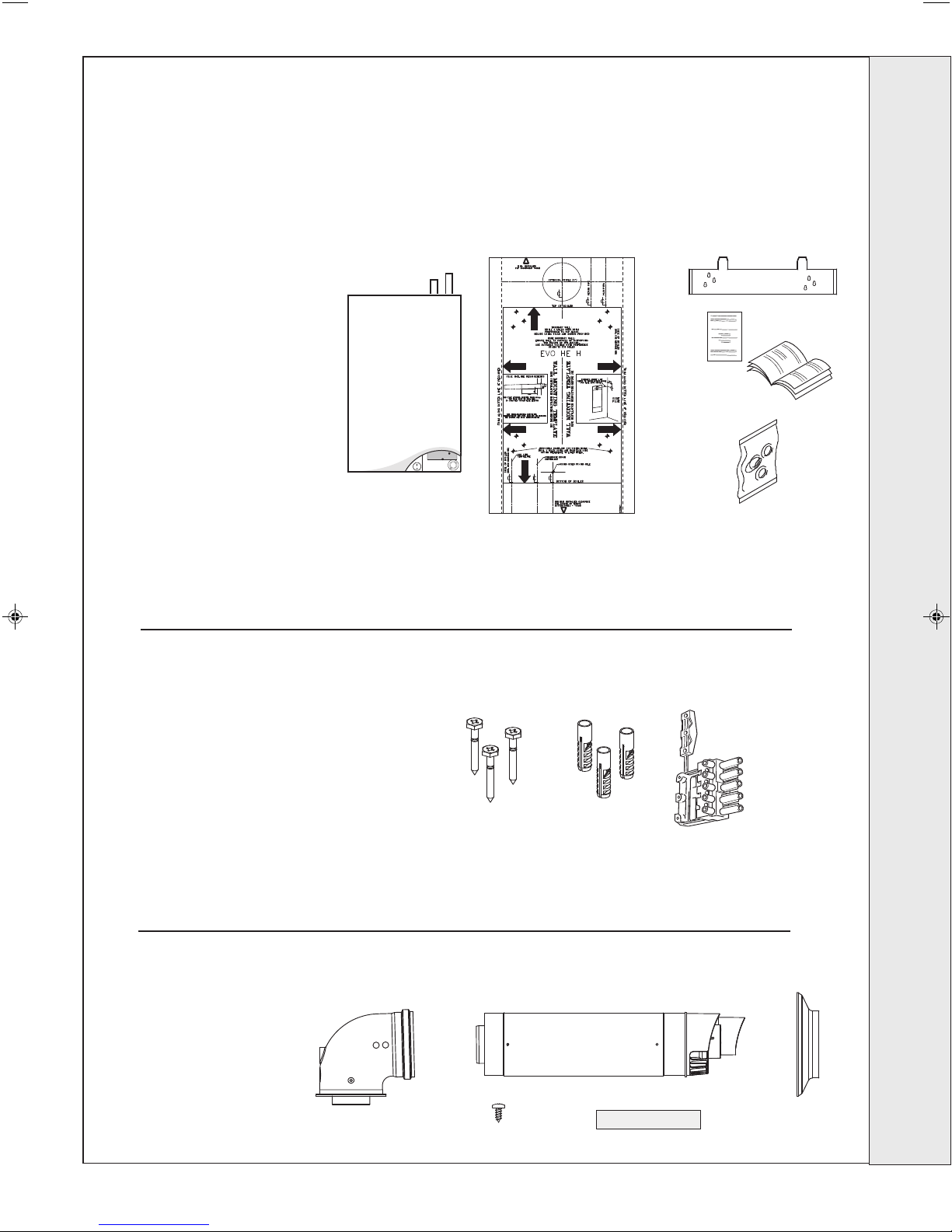
UNPACKING
The boiler is supplied fully assembled in one Pack A,
together with a telescopic flue assembly for lengths up to
595mm, rear or side flue outlet, in Pack B.
Unpack and check the contents.
Pack A Contents
A The boiler
B Wall mounting template
on cardboard
C Wall mounting plate
D 1 year guarantee form
E These Installation & Servicing
User’s Instructions
F Hardware pack
B
A
nm7890
C
D
E
F
INSTALLATION
Hardware Pack
A 50mm x No.14 wood screws - 3 off
B Wall plugs (TP2B ) - 3 off
C Mains connector - 1 off
B Pack Contents
A Telescopic flue terminal
B Flue turret
C Rubber Terminal Wall Seal
D Screw
E Sealing Tape
A
nm8464
B
A
D
B
E
C
C
isfu8751d
evo HE H - Installation & Servicing
15
INSTALLATION
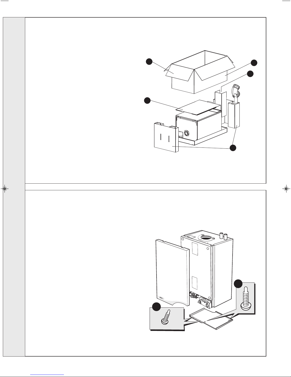
12
PACKAGING REMOVAL
1. Ensure the boiler is stood correctly, as marked on
the carton.
2. Cut and remove the strapping.
3. Fold back the top flaps to gain access to the wall
mounting plate, literature and wall mounting
template. (located on protective packaging piece).
4. Remove the instructions and read thoroughly before
unpacking the product.
INSTALLATION
5. Remove the hardware pack and keep in a safe
place.
6. When ready for installation lift off the outer sleeve.
7. Remove the top protection packing/template and
save for further use.
8. Remove the two packaging ends.
3
7
nm8231
8
6
5
13
BOTTOM PANEL REMOVAL
1. To remove the front panel remove the 2 screws from the
bottom panel.
2. Lift the front panel up and off the top pegs.
3. To remove the bottom panel remove the 2 screws.
4. Pull the RH side of the panel down. Slide it to the right
and withdraw.
nm7819
3
1
16
evo HE H - Installation & Servicing
INSTALLATION
Wall Thickness X
160 mm
160 + S = 193mm
nm8943
195mm
195mm
Wall Thickness X
Side flue length L
14
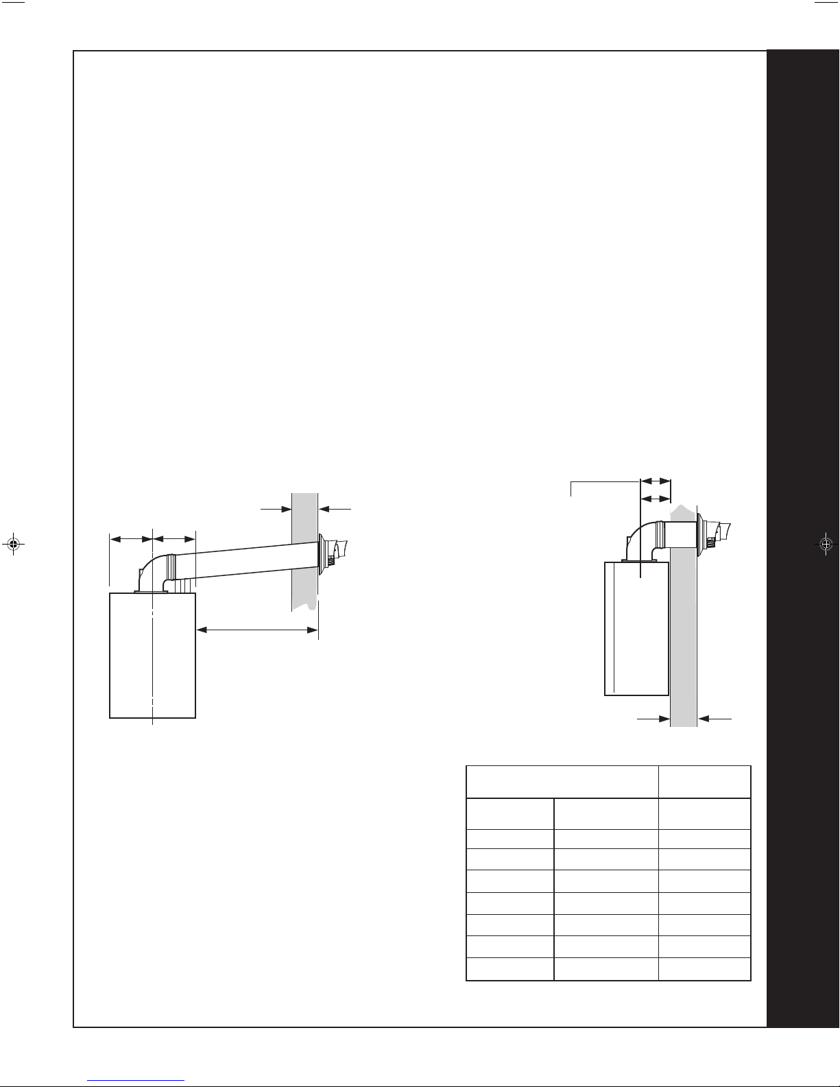
DETERMINING THE FLUE LENGTH AND FLUE PACKS REQUIRED
IMPORTANT. The boiler MUST be installed in a vertical position.
FLUE KITS
Pack B - supplied as standard.
Finishing Kit - supplied as an optional extra.
Pack D - optional extension kit for side flue or rear flue outlet.
Screw Kit - Optional kit for mechanical fixing of flue joints
Refer to 'Flue Extension Ducts'
Note. MAXIMUM FLUE LENGTHS:
HORIZONTAL FLUE - 6M
ROOF FLUE KIT - 7.5M
POWERED VERTICAL FLUE KIT - 5M PRIMARY AND 17M SECONDARY IS A TYPICAL
MAXIMUM LENGTH. For alternative maximum lengths
O
90
ELBOW KIT 60/100 (EQUIVALENT FLUE LENGTH RESISTANCE = 1M)
45O ELBOW KIT 60/100 (EQUIVALENT FLUE LENGTH RESISTANCE = 0.6M)
MINIMUM HORIZONTAL FLUE LENGTHS - TELESCOPIC TERMINAL = 370MM
(Centre Line of turret to outside of wall terminal) - ONE PIECE TERMINAL = 285MM
refer to Powered Vertical Instructions.
Dimension X - Wall thickness.
Dimension L - Wall thickness plus boiler spacing.
Dimension S - Stand-off frame depth = 33mm.
SIDE FLUE
REAR FLUE
Notes.
1. When extension ‘D’ packs are used the flue duct MUST be
inclined at 1.5 degrees to the horizontal to allow condensate to
drain back into the boiler and out through the condensate drain.
2. If the telescopic ‘B’ pack or horizontal flue terminal (600 long)
only are used, they may be mounted horizontally. The 1.5
degrees is taken care of by the inclination of the flue within the air
pipe
3. If the boiler is to be installed with downward piping routed behind
the boiler then the optional stand-off kit should be used. Care
must be taken when cutting the ducts and marking the wall to suit
this condition.
4. Only use water as a lubricant during assembly.
It is recommended that a support bracket is fitted for every 1 metre of extension pipe used and also at every joint to ensure
pipes are held at the correct angle. If a slip joint coupling is used then a support bracket must be used to secure the collar.
evo HE H - Installation & Servicing
Total Flue length dimension Flue
(measuring from CL of turret to outside wall)
Rear flue Side flue Extra packs
dim. X+160 dim. L+195 required
Up to 595 mm Up to 595 mm none
Up to 1545 mm Up to 1545 mm Pack D - 1 off
Up to 2495 mm Up to 2495 mm Pack D - 2 off
Up to 3445 mm Up to 3445 mm Pack D - 3 off
Up to 4395 mm Up to 4395 mm Pack D - 4 off
Up to 5345 mm Up to 5345 mm Pack D - 5 off
Up to 6000 mm Up to 6000 mm Pack D - 6 off
FLUE OUTLET
17
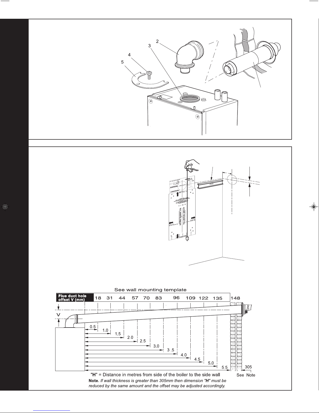
15
nm9287
V - See Diagram Below
Extended centre line
155
FLUE ASSEMBLY - Exploded View
An optional flue duct extension kit is required
for wall thicknesses greater than :
Side 395mm
Rear 435mm
LEGEND
1. Duct assembly.
2. Flue turret.
3. Turret gasket.
4. M5 x 10 pozi screw.
5. Turret clamp.
INSTALLATION
1
Rear flue arrangement shown
16
WALL MOUNTING TEMPLATE
The wall mounting template is located on the internal top
protective packaging.
Note.
The template shows the positions of the fixing holes and
the rear flue hole centre for standard installation. Care
MUST be taken to ensure the correct holes are drilled.
1. Tape template into the selected position. Ensure
squareness by hanging a plumbline as shown.
2. If fitting a side flue extend the flue centre line onto the side
wall and measure in 155mm for standard installation.
Note. If using stand-off kit distance increases to 188mm.
3. Mark onto the wall the following:
a The wall mounting plate screw positions (choose one
from each side with preference to top holes).
b. The position of the flue duct hole (see diagram below).
Note. Mark the centre of the hole as well as the
circumference.
4. Remove the template from the wall.
nm8752
FLUE OUTLET
18
nm8731
evo HE H - Installation & Servicing
 Loading...