

Evo FX20 User Manual
USER’S MANUAL
FX20 MOTORIZED TREADMILL
MODEL NUMBER: FX20
USER WEIGHT LIMITATION: 265lbs.
TOLL FREE CUSTOMER SERVICE NUMBER: 1.888.800.1167
SERIAL NUMBER (found on frame):

FX20 MOTORIZED TREADMILL
Visit us at: www.evofitness.com
2
PRECAUTIONS
Precautions:
WARNING: To reduce the risk of burns, fire, electric shock, or injury to persons, read the following important precautions
and information before operating the treadmill. It is the responsibility of the owner to ensure that all users of this treadmill
are adequately informed of all warnings and precautions.
• Use the treadmill only as described in this manual.
• Place on a level surface, with 2 meters (6 feet) of clearance behind it. Do not place the treadmill on any surface
that blocks air openings. To protect the floor or carpet from damage, place a mat under the treadmill.
• When choosing a location for the treadmill make sure that the location and position permit access to a plug.
• Keep the treadmill indoors, away from moisture and dust. Do not put the treadmill in a garage or covered patio,
or near water.
• Do not operate the treadmill where aerosol products are used or where oxygen is being administered.
• Keep children under the age of 12 and pets away from the treadmill at all times.
• The treadmill should not be used by persons weighing more than 120kgs. (265lbs.)
• Never allow more than one person on the treadmill at a time. Wear appropriate exercise clothing when using the
treadmill. Do not wear loose clothing that could become caught in the treadmill. Athletic support clothes are
recommended for both men and women. Always wear athletic shoes. Never use the treadmill with bare feet,
wearing only stockings, or in sandals.
• When connecting the power cord, plug the power cord into a grounded circuit. No other appliance should be on
the same circuit.
• Always straddle the belt and allow it to start moving before stepping onto the belt.
• Always examine your treadmill before using to ensure all parts are in working ord er.
• Allow the belt to fully stop before dismounting.
• Never insert any object or body parts into any opening.
• Follow the safety information in regards to plugging in your treadmill.
• Keep the power cord away from the incline wheels and do not run the power cord underneath your treadmill. Do
not operate the treadmill with a damaged or frayed power cord.
• Always unplug the treadmill before cleaning and/or servicing. Service to your treadmill should only be performed
by an authorized service representative, unless authorized and/or instructed by the manufacturer. Failure to
follow these instructions will void the treadmill warranty.
• Never leave the treadmill unattended while it is running.

FX20 MOTORIZED TREADMILL
Visit us at: www.evofitness.com
3
POWER REQUIREMENTS
Power Requirements:
IMPROPER CONNECTION OF THE EQUIPMENT GROUNDING CONNECTOR CAN RESULT IN A RISK OF AN
ELECTRIC SHOCK. CHECK WITH A QUALIFIED ELECTRICIAN OR SERVICE MAN IF YOU ARE IN DOUBT AS TO
WHETHER THE PRODUCT IS PROPERLY GROUNDED. DO NOT MODIFY THE PLUG PROVIDED WITH THE
PRODUCT, IF IT WILL NOT FIT THE OUTLET; HAVE A PROPER OUTLET INSTALLED BY A QUALIFIED
ELECTRICIAN.
This treadmill can be seriously damaged by sudden voltage changes i n your home’s electrical power. Voltage spikes,
surges and noise interference can result from weather conditions or from other appliances being turned on or off. To
reduce the possibility of treadmill damage, always use a surge protector (not include d) with your treadmill.
Surge protectors can be purchased at most hardware stores. The manufacturer recommends a single outlet surge
protector with a UL 1449 rating as a Transient Voltage Surge Suppressor (TVSS) with a UL suppressed voltage rating of
400V or less and an electrical rating 120VAC, 15 amps.
This treadmill must be grounded to reduce the risk of electrical shock. Grounding provides a path of least resistance for
electric current, should the treadmill malfunction. This treadmill comes with an electrical cord having an equipmentgrounding conductor and a grounding plug. Always plug the power cord into a surge protector, and pl ug the surge
protector into an appropriate outlet that is properly installed and grounded in accordance with all local codes and
ordinances.
This product is for use on a nominal 120-volt circuit, and has a grounding plug that looks like the plug illu strated in the
drawing below.

FX20 MOTORIZED TREADMILL
Visit us at: www.evofitness.com
4
PREASSEMBLY
Open the boxes:
You are now ready to open the boxes of your new equipment. Make sure to inventory all of the parts that are included in
the boxes. Check the Hardware Comparison Chart for a full count of the number of parts included for this product to be
assembled properly. If you are missing any parts or have any assembly questions call the manufactur er.
Gather your tools:
Before starting the assembly of your unit, make sure that you have gathered all the necessary tools you may require to
assemble the unit properly. Having all of the necessary equipment at hand will save time and make the assembly quick
and hassle-free.
Clear your work area:
Make sure that you have cleared away a large enough space to properly assemble the unit. Make sure the space is free
from anything that may cause injury during assembly. After the unit is fully assembled, make sure there is a comfortable
amount of free area around the unit for unobstructed operation.
Invite a friend:
Some of the assembly steps may require heavy lifting. It is recommended that you obtain the assistance of another
person when assembling this product.
User Weight Limitation:
Please note that there is a weight limitation for this product. If you weigh more than 120kgs. (265lbs.) it is not
recommended that you use this product. Serious injury may occur if the user’s weight exceeds the limit shown
here. This product is not intended to support users whose weight exceeds this limit.
FX20 MOTORIZED TREADMILL
Visit us at: www.evofitness.com
5
HARDWARE COMPARISON CHART
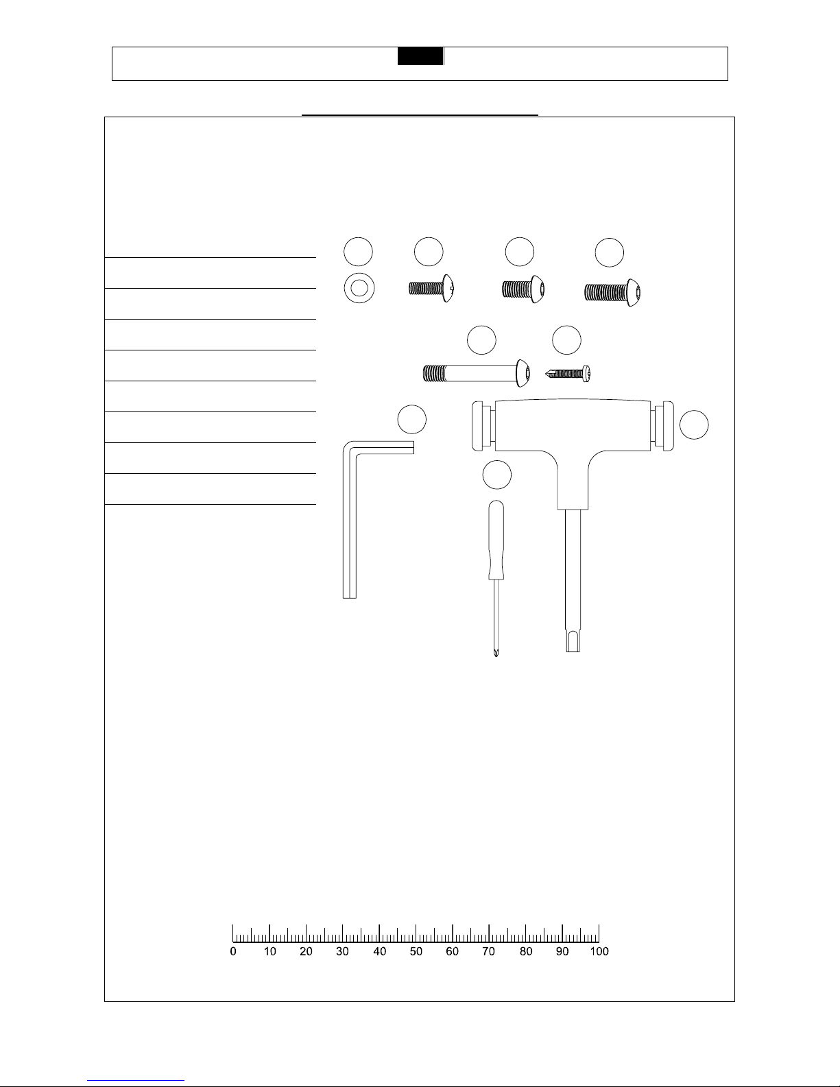
Hardware chart:
For your convenience, we have identified the hardware used in the assembly of this product. This chart is provided to
help you identify those items that may be unfamiliar to you.
NO. DESCRIPTION QTY.
70 M4 x 15mm Screw 19
76 M6 X 15mm Screw 2
77 M8 x 18mm Allen Bolt 2
78 M8 x 50mm Allen Bolt 2
88 Washer 4
100 M8 x 30mm Screw 2
A Allen Key Tool 1
B Screw Driver Tool 1
C Allen Wrench Tool 1
88
76
77
100
78
70
A
B
C
MILIMETERS

FX20 MOTORIZED TREADMILL
Visit us at: www.evofitness.com
6
PARTS LIST
NO. DESCRIPTION QTY. ORDER NO.
NO. DESCRIPTION QTY. ORDER NO.
1
Computer Insert 1
20-01 28
Fold Up Support Bushing 2
20-28
2
Console Housing Upper
1
20-02 29
Fold Up Support Insert 1
20-29
3
Console Housing Bottom
1
20-03 30
Nut 1
20-30
4
Safety Key 1
20-04 31
Spacer 1
20-31
5
EKG Pulse Sensor 2
20-05 32
Foot Up Locker 1
20-32
6
Front Handlebar 1
20-06 33
Base Frame Rubber
Cushion - Rear
2
20-33
7
Handlebar Cover Left #1
1
20-07 34
Transportation Wheel 2
20-34
8
Handlebar Cover Left #2
1
20-08 35
Console Plate 1
20-35
9
Handlebar Cover Right #2
1
20-09 36
Motor Hood 1
20-36
10
Handlebar Cover Right #1
1
20-10 37
Side Rail 2
20-37
11
Handlebar Grip 2
20-11 38
Deck End Cap - Right 1
20-38
12
Handlebar End Cap 2
20-12 39
Deck End Cap - Left 1
20-39
13
EKG Pulse Wire 2
20-13 40
Motor Bottom Cover 1
20-40
14
Motion Control
Sensor
2
20-14 41
Motor Hood Side Cover Right
1
20-41
15
Upright - Left 1
20-15 42
Motor Hood Side Cover Left
1
20F-42
16
Upright - Right 1
20-16 43
Front Roller 1
20-43
17
Upright Base Cover Left #1
1
20-17 44
Rear Roller 1
20-44
18
Upright Base Cover Left #2
1
20-18 45
Running Belt 1
20-45
19
Upright Base Cover Right #2
1
20-19 46
Motor Holder 1
20-46
20
Upright Base Cover Right #1
1
20-20 47
Driving DC Motor 1
20-47
21
Upright Base CoverUpper
2
20-21 48
Driving Belt 1
20-48
22
Base Frame 1
20-22 49
Elevation Control Board 1
20-49
23
Fold Up Support 1
20-23 50
Motor Control Board 1
20-50
24
Power Plate 1
20-24 51
Running Deck 1
20-51
25
Power Plate Plastic
Frame
1
20-25 52
Side Rail Guider 6
20-52
26
Base Frame Tube
End Cap - Front
2
20-26 53
Running Deck Rubber
Cushion
8
20-53
27
Base Frame Tube
End Cap - Rear
2
20-27 54
Elevation Support Frame 1
20-54

FX20 MOTORIZED TREADMILL
Visit us at: www.evofitness.com
7
PARTS LIST
NO. DESCRIPTION QTY. ORDER NO.
NO. DESCRIPTION QTY. ORDER NO.
55
Elevation Support
Frame End Cap #1
2
20-55 82
M10 x 68mm Allen Bolt 1
20-82
56
Plastic Clamp Upper
2
20-56 83
Pivot Shaft 1
20-83
57
Plastic Clamp Bottom
2
20-57 84
Deck Wheel Bolt 2
20-84
58
Bracket 2
20-58 85
Fold Up Stopper 1
20-85
59
Elevation Support
Frame End Cap #2
2
20-59 86
Elevation Support Frame
Fixing Bolt
2
20-86
60
Deck Frame 1
20-60 87
6mm Washer 3
20-87
61
Elevation Motor 1
20-61 88
Washer 10
20-88
62
Elevation Motor Gear
Sleeve
1
20-62 89
10mm Washer 2
20-89
63
Gas Shock 1
20-63 90
M8 Nylon Nut 7
20-90
64
Deck Wheel 2
20-64 91
M10 Nylon Nut 2
20-91
65
PU Cushion 1
20-65 92
M10 Nut 1
20-92
66
20 x 40mm Washer 2
20-66 93
N/A
20-93
67
Driving Belt
Adjustment bolt
1
20-67 94
Gas Shock Fixing
Spacer
2
20-94
68
M16 Nylon Nut 1
20-68 95
Base Frame Rubber
Cushion - Front
4
20-95
69
Deck Rubber
Cushion Bolt
8
20-69 96
Elevation Control Board
Fixing Insert
6
20-96
70
M4 x 15mm Screw 27
20-70 97
Handlebar 1
20-97
71
Console Housing
Screw
10
20-71 98
Running Deck Cross
Brace 1 20-98
72
Plastic Fixing Insert 6
20-72 99
Running Deck Cross
Brace Foam 1 20-99
73
Side Rail Guider
Screw
12
20-73 100 M8 x 30mm Screw 4 20-100
74
Rubber Cushion
Screw
4
20-74 101
SPRING 1
20-101
75
Roller Adjustment
Bolt
3
20-75 102
TRANSPORTATION
WHEEL BRACKET 1
20-102
76
M6 x 15mm Screw 4
20-76
77
M8 x 18 Allen Bolt 6
20-77
78
M10 x 50mm Allen
Bolt
4
20-78
79
Transportation Wheel
Bolt
2
20-79
80
Elevation Motor
Fixing Bolt
1
20-80
81
M10 x 63mm Bolt 1
20-81

FX20 MOTORIZED TREADMILL
Visit us at: www.evofitness.com
8
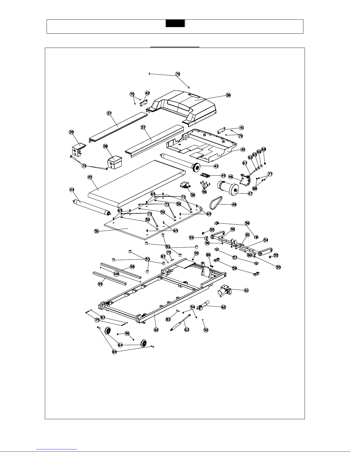
PARTS DIAGRAM
A MAJORITY OF THE PARTS SHOWN HERE HAVE BEEN PREASSEMBLED AT THE FACTORY.
FX20 MOTORIZED TREADMILL
Visit us at: www.evofitness.com
9
PARTS DIAGRAM
A MAJORITY OF THE PARTS SHOWN HERE HAVE BEEN PREASSEMBLED AT THE FACTORY.
FX20 MOTORIZED TREADMILL
Visit us at: www.evofitness.com
10
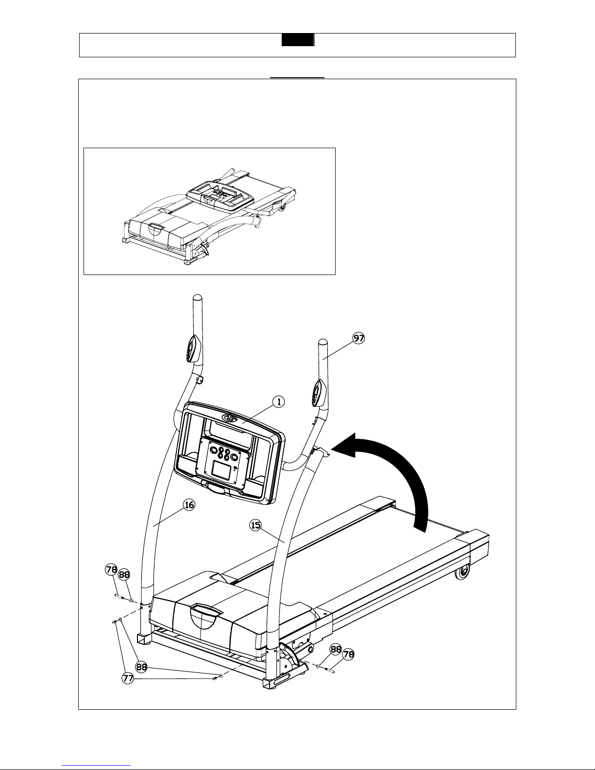
ASSEMBLY
STEP 1:
Remove your treadmill from the carton and place it on the floor in an open area as shown in FIG 1.
Raise the Right and Left Uprights (16 and 15) and secure with two Washers (88) and M10 x 58mm Bolts (78).
FIG. 1
 Loading...