

Page 1

R
EVent® 48E FMS Display Cooking Station
Operator’s Manual
Indoor Use Only
Ductless Downdraft Ventilation
Cooking Equipment
E470119
E335515
Rev-2017 v1
Page 2
YOUR EVO EVENT COOKING UNIT IS EQUIPPED WITH
AN AUTOMATIC & MANUAL ACTUATED
FIRE SUPPRESSION SYSTEM.
FAILURE TO COMMISSION AND ACTIVATE THE FIRE
SUPPRESSION SYSTEM BY AN “AUTHORIZED BUCKEYE
FIRE EQUIPMENT DEALER” MAY RESULT IN SYSTEM
FAILURE, INJURY, OR DEATH.
WARNING
Page 3

R
EVent 48E
3
CONTENTS
SAFETY WARNINGS 4
LIMITED WARRANTY 5
INTRODUCTION
What is Live-Action Display Cooking 7
Handling Grease and Smoke Laden Air 7
Unique Innovation 7
About Evo, Inc. 7
The Evo EVent 48E Teppanyaki Table 8
EQUIPMENT FEATURES
Know Your EVent 48E Cooking Station 9
CONTROL PANEL
Status Screen 10
Startup Screen 11
Ventilation Startup 12
Ventilation Startup - FAULT 13
Ventilation Startup - FAULT Service Instruction 14
Cooktop Startup 15
Administration Settings - Overview 16
Administration Settings - Select Temperature Presets 17
User Settings - Use Manual Temperature 19
Factory Settings - Overview 20
Factory Settings - Actual Temperature 21
Factory Settings - Set Temperature Offsets 22
MAINTENANCE
Cleaning - Stainless Steel Panels 23
Cleaning - Granite Cooktop Surfaces 24
Cleaning - The Griddle Surface 25
Cleaning - Ventilation Inlet Aperture 26
Cleaning - Ventilation Inlet Duct 27
Cleaning - The Crumb Drawer 28
Cleaning - The Grease Filter 29
Cleaning - The Grease Filter Enclosure Part 1 30
Cleaning - The Grease Filter Enclosure Part 2 31
Cleaning - The Electrostatic Precipitator (ESP) Part 1 32
Cleaning - The Electrostatic Precipitator (ESP) Part 2 33
Cleaning - The Electrostatic Precipitator Pre-Filter 34
Cleaning - The Electrostatic Precipitator Bottom Pan 35
Replacing - The Disposable Charcoal Post Filter 36
TROUBLESHOOTING ISSUES
On/Off Button Will Not Respond 37
The Fan Starts Then Stops After 5-10 Seconds 37
The Fan Starts Then Stops When Cooking 37
The Display Appears Functional But The Fan Does Not Start 37
The Display Is Grey or The Display Does Not Respond 38
The Upper Left Side Heater Is Over Heating 38
The COOK Button Is ON But The Heaters Are Not Heating 38
The Display Shows Red Fault Indicators 38
CONTROL PANEL DISPLAY - FAULT INDICATORS
FAULT #1 - Aperture Inlet Duct 39
FAULT #2 - Crumb Drawer 39
FAULT #3 - Grease Filter 39
FAULT #4 - Grease Drawer 39
FAULT #5 - Pre-Filter 39
FAULT #6 - Charcoal Filter 39
APPENDIX 1-6
#1 REQUIRED EVENT SYSTEM MAINTENANCE SCHEDULE 40-41
#2 FILTER AND SURFACE CLEANING MAINTENANCE SCHEDULE 42
#3 CLEANING THE COOKING SURFACE 43
#4 FIRE SUPPRESSION SYSTEM 44-45
#5 RESTARTING AFTER A FIRE SYSTEM DISCHARGE 46
#6 FIRE SYSTEM ALARM MICRO SWITCH 47
#7 SPECIFICATIONS 48
Repair Service Provided By Evo, Inc.
In Affi liation With National Service Cooperative
Please call 866-626-1802
Monday - Friday 8am-6pm pst
Page 4
R
EVent 48E
4
FOR YOUR SAFETY - Storing Flammable Materials
DO NOT STORE OR USE GASOLINE OR OTHER FLAMMABLE VAPORS OR LIQUIDS IN THE VICINITY OF THIS OR ANY OTHER
APPLIANCE.
WARNING - Do Not Misuse Equipment
IMPROPER INSTALLATION, ADJUSTMENT, ALTERATION, SERVICE OR MAINTENANCE CAN CAUSE PROPERTY DAMAGE,
INJURY, OR DEATH. READ THE INSTALLATION, OPERATING AND MAINTENANCE INSTRUCTIONS THOROUGHLY BEFORE
POSITIONING, INSTALLING, MAINTAINING OR SERVICING THIS EQUIPMENT.
PLEASE READ ALL SECTIONS OF THIS MANUAL AND RETAIN FOR FUTURE REFERENCE.
THE UNIT WHEN INSTALLED, MUST BE ELECTRICALLY GROUNDED AND COMPLY WITH LOCAL CODES, OR IN THE ABSENCE OF LOCAL
CODES, WITH THE NATIONAL ELECTRICAL CODE.
Users are cautioned that maintenance and repairs must be performed by an Evo, Inc. Authorized Service Agent using genuine
Evo, Inc. Replacement parts. Evo, Inc. will have no obligation with respect to any product that has been improperly installed,
adjusted, operated or maintained in accordance with national and local codes or installation instructions provided with the
product, or any product that has its serial number defaced, obliterated or removed, or which has been modifi ed or repaired
using unauthorized parts or by unauthorized service agents. The information contained herein, (including design and parts
specifi cations), may be superseded and is subject to change without notice.
• This unit must be operated by a qualifi ed person.
• DO NOT operate without reading this manual.
• DO NOT attempt to repair or replace any part of this appliance unless all main power supplies have been disconnected.
• DO NOT clean this appliance unless the power supply is disconnected.
• USE EXTREME CAUTION in setting up, operating and cleaning this appliance to avoid coming in contact with hot surfaces
(including parts). Wear suitable protective clothing or use proper utensils to prevent the risk of burns.
IMMEDIATELY INSPECT FOR SHIPPING DAMAGE
All containers must be examined for damage before and during unloading. The freight carrier has assumed responsibility for its
safe transit and delivery. If equipment is received damaged, either apparent or concealed, a claim must be made with the
delivering freight carrier.
SAFETY WARNINGS
Page 5

R
EVent 48E
5
LIMITED WARRANTY
Commercial Limited Warranty for the EVent® 48E
Evo, Incorporated warrants to the original commercial foodservice purchaser that the Evo Cooking Station shall be free from defects in materials and
workmanship under normal and reasonable use for One (1) year from the original installation date. This warranty is for the original use purchaser and
is non-transferable. Evo promises to replace, at its determination, any product or component that is defective during this initial one year period. This
document covers the warranty information for the Evo EVent® 48E Teppanyaki Table. You will fi nd in this warranty document the following details:
• what the warranty covers;
• critical need to maintain fi lters;
• what the period of coverage is;
• what you will do to correct problems;
• how you, as the customer, can get warranty service.
As you begin cooking operations with the EVent® 48E, it is critical to learn how to maintain the cooking station, with a particular emphasis on
monitoring and cleaning the fi lters within the ventilation system.
We stand behind our Evo Ductless Downdraft Ventilation Cooking Equipment, but you, as the customer will need to clean the four (4) ventilation
system fi lters on a minimum monthly basis, and more frequently depending on the volume of foods being cooked.
A. The Evo, Incorporated Warranty Covers The Entire Cooking Station
The company will supervise the correct installation of the EVent Cooking Station(s) in your service area. The company has a contract with National
Service Cooperative, “NSC”. This fi rm has national coverage with installation and service representatives across the United States.
• If you are experiencing a cooking problem, we ask you to call the company directly (503) 626-1802;
• In most instances, the problem with the EVent Cooking Station should be resolved with removing and proper cleaning of the four fi lters;
• The charcoal fi lter is a disposable fi lter and needs to be inspected every two to three weeks, completely replaced once a month; and
• The crumb tray, doors and fi lters (DRY, NOT WET FROM DISHWASHER) must be returned to the proper location in the unit.
B. The Evo, Incorporated Warranty does not include Damage to the Cooking Station due to fi lter neglect or abuse.
Each EVent® Cooking Station purchased includes four (4) fi lters that must be monitored, checked on a minimum monthly basis, and more frequently
depending on the volume of foods being cooked, and cleaned properly:
1. The washable stainless steel fi lter.
2. The washable aluminum pre-fi lter.
3. The washable Electrostatic Precipitator fi lter cartridge (ESP).
4. The fi nal, disposable, fi lter is a charcoal activated post fi lter.
The fi rst three (3) fi lters must be removed and washed at least once a month; however, weekly visual monitoring is strongly recommended. The last
fi lter, the disposable charcoal fi lter should be visually checked each week. After 3 to 4 weeks of operation, the disposable charcoal fi lter must be
removed and a fresh, new fi lter installed in the unit. Proper fi lter maintenance and cleaning will ensure successful cooking operations. Ignoring and
abusing the Evo EVent® Cooking Station fi lter maintenance MAY RESULT IN WARRANTY COVERAGE TERMINATION.
C. The discharge of the fi re suppression system is likely to damage the EVent® unit. The Warranty is no longer valid after the fi re
suppression system is discharged.
It is critical to call Evo, Incorporated (503) 626-1802 to report the fi re suppression system was used on the EVent unit.
Page 6

R
EVent 48E
6
D. The Warranty period for the entire EVent unit covers the fi rst year of operation.
The warranty starts the day the EVent Cooking Station has been installed and continues for 365 days (1 year).
The warranty is not assignable and applies only in favor of the original purchaser / owner to whom the EVent® unit was delivered. Any such transfer
shall void the warranties herein made.
E. What is not covered by this warranty
Cleaning the fi lters on a regular basis is required to maintain the warranty, damage resulting from the failure to perform normal maintenance as
outlined in the owner’s manual will result in warranty termination.
Voltage conditions, blown fuses, open circuit breakers or any other damage due to the inadequacy or interruption of electrical services will result in
warranty termination.
Damages as a result of fl oods, winds, fi res, lightning, accidents, corrosive environment, improper installation or installation not in accordance with local
electrical codes will result in warranty termination.
Cosmetic damage, including scratches, dents, chips or other damage to the fi nish of the table, cook surface, stainless steel are not covered in the
warranty.
The EVent® table with original model / serial numbers that have been removed, altered or cannot be easily determined may result in warranty
termination.
F. If you are calling with a service problem, please be prepared to relay the following information:
1. How and when the Cooking Station stopped operating.
2. Whether or not the fi lters were recently cleaned and inserted into the Cooking Station.
3. The Evo EVent Cooking Station Serial Number.
LIMITED WARRANTY
Page 7

R
EVent 48E
7
INTRODUCTION
What is Live-Action Display Cooking
Live-Action Display Cooking is performed by a chef in front of an audience where the chef creates theater and participation by engaging people with the
sights, sounds and fl avors of freshly prepared food. Every culture cooks foods in an open kitchen or outdoors where food preparation is equal parts fl avor and
entertainment, and the cooking equipment is as varied as our culture such as American barbecue, French rotisserie and Brazilian churrasco, to Chinese wok and
Japanese teppan cooking.
Handling Grease and Smoke Laden Air
Of the thousands of variations of display cooking equipment a chef can employ, one of the most versatile cooking platforms is the heated fl at plancha or teppan
griddle plate. Unfortunately when used indoors, this style of griddle plate inevitably produces grease laden air which is an undesirable byproduct that can be a
health hazard to both the chef and the audience. The conventional way of dealing with this issue is to install ventilation devices such as a grease hood above the
griddle. This hood is connected to an air/grease duct that leads to the outside, providing the air passage through which grease laden air can be removed by a
suction motor (often installed at the end of the air duct).
Unique Innovation
The Evo EVent® Ductless Downdraft Ventilation Cooktop is an innovative design that includes a high-effi ciency griddle integrated to a
ventilation system that extracts air across the griddle surface through a series of fi lters including an electrostatic precipitator that removes
smoke and grease particulates before exhausting clean air.
This high-effi ciency griddle and ventilation system is individually patented technologies which benefi t operators, chefs, and restaurant patrons by reducing the
risk of worker related respiratory illness and contributes to better air quality of the restaurant.
About Evo, Inc.
Evo was founded by innovative food people with a passion for cooking and entertaining. As a cooking equipment manufacturer, it’s our love of connecting
people around food that guides everything we do. Since 2001, we have built a full line of exceptionally energy-effi cient gas and electric, indoor and outdoor,
commercial and residential, fl attop cooking equipment, all designed to create a social cooking experience. Made in America, Evo equipment is the leading live-
action display cooking equipment in the world and built to last a lifetime. Our commercial cooktops are used by foodservice professionals and top chefs as a
versatile cooking platform, and as a conduit to communicate a fresh-prepared, farmer-to-table message. Evo commercial equipment can be found at Whole
Foods, Google, Apple, Microsoft, Marriott, Sheraton, Hyatt, Hilton, and hundreds of other A-list companies. Our residential cooking appliances compliment indoor
and outdoor kitchens, and are used by thousands of consumers as a fun, healthy, and social way to cook for family and friends.
Page 8
R
EVent 48E
8
The team at Evo, Inc. and our engineering partners collaborated with
teppanyaki master chefs to create the world’s most advanced ductless
downdraft ventilation teppanyaki cooking table.
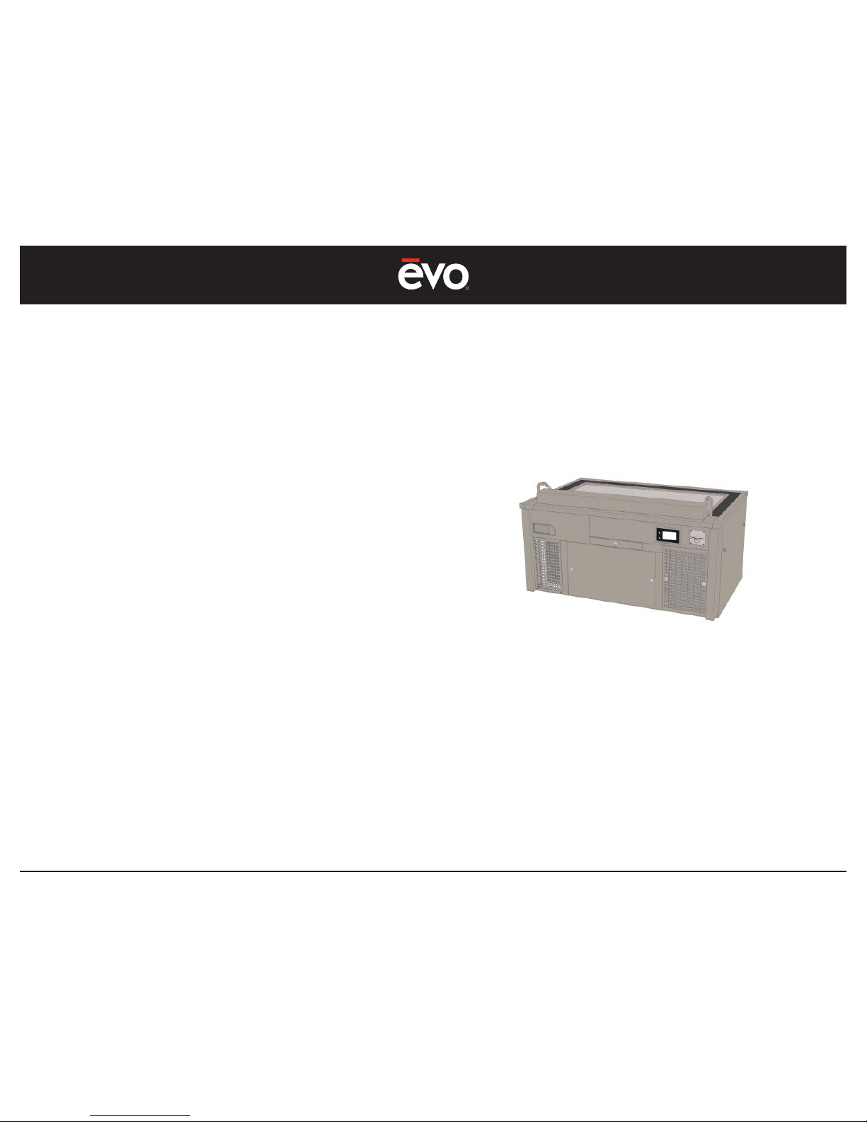
Conceived and designed from the ground up, the Evo
EVent® teppanyaki table is designed to be operated without
an overhead or ducted ventilation hood, or a secondary fi re
suppression system. The EVent® is fully self contained, with a UL
certifi ed integral grease and smoke capture system and a UL
certifi ed internal fi re suppression system.
Easy to use and maintain, the EVent® operates on 208V - 220V
electrical supply that runs the heating elements and the ductless
downdraft ventilation system. The high effi ciency 4-zone heating
elements are electronically controlled with user adjustable
temperature presets and a conservation cycle that only applies
power to the cooking surface when needed.
The ventilation system is constructed of fully welded stainless steel and
utilizes washable primary grease fi lters, a washable electrostatic precipitator
fi lter cartridge, and a replaceable activated charcoal post-fi lter. For
convenience, all duct and fi lter cleaning happens from the chefs-side of the
table.
The EVent® is portable and designed to be wheeled into a
restaurant and easily repositioned. If table arrangements within
the restaurant change you can simply move and relocate the
table to a new position. If a restaurant location changes, the
EVent® can be moved to a new location and quickly setup for
operation.
Chefs Side
Guest Side
Ensure cooktop is on level surface
The Evo EVent® 48E Teppanyaki Table
INTRODUCTION
Page 9
R
EVent 48E
9
EQUIPMENT FEATURES
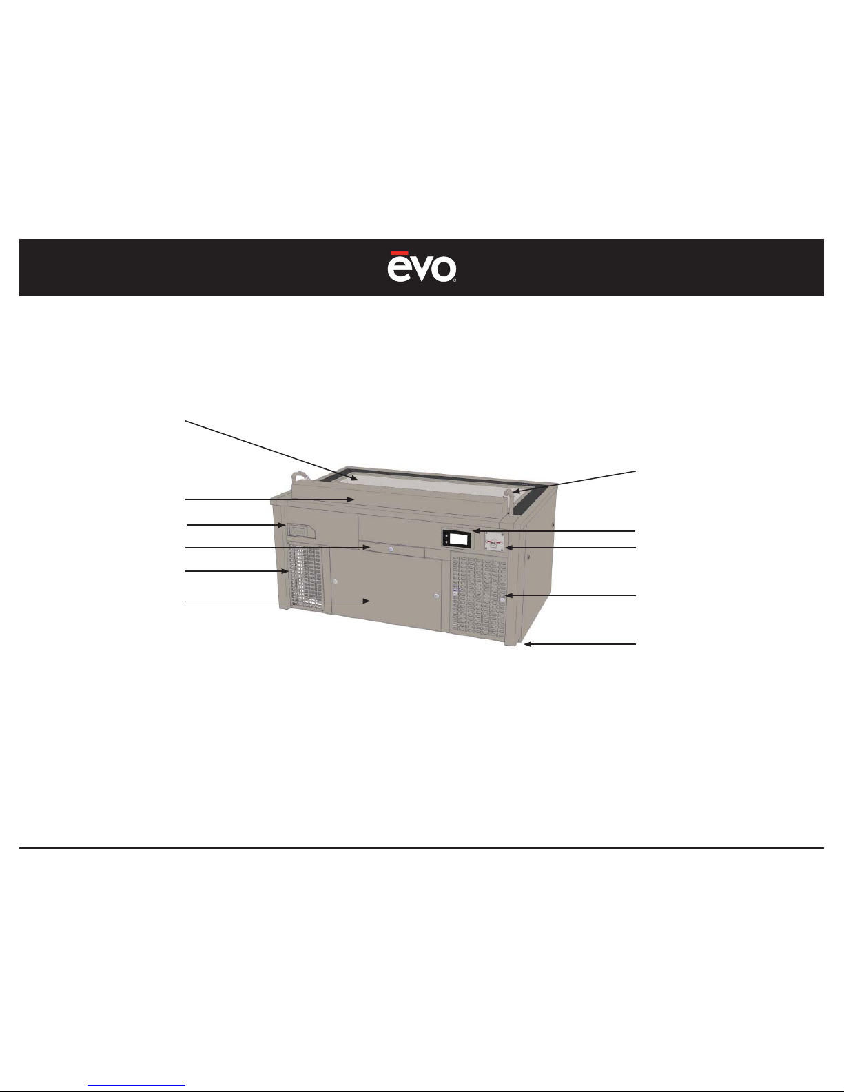
Know Your EVent® 48E Teppanyaki Table
High Effi ciency Electric
Teppan Cooktop
Emergency Fire Pull Station
Grease Filter Box
Caster Wheels and
Leveling Feet At
Each 4 Corners
Fire Suppression Nozzles
Air Inlet Aperture
Control Panel
Crumb Drawer
Air Discharge Panel
Pre-Filter,
Electrostatic Precipitator,
and Charcoal Filter
Spillover Drawer
Page 10
R
EVent 48E
10
ON / OFF
COOK
www.evoamerica.com
COLD SURFACE
R
EVent Display Cooking Station
Version x.xx.x
Evo, Inc. Oregon USA
503-626-1802
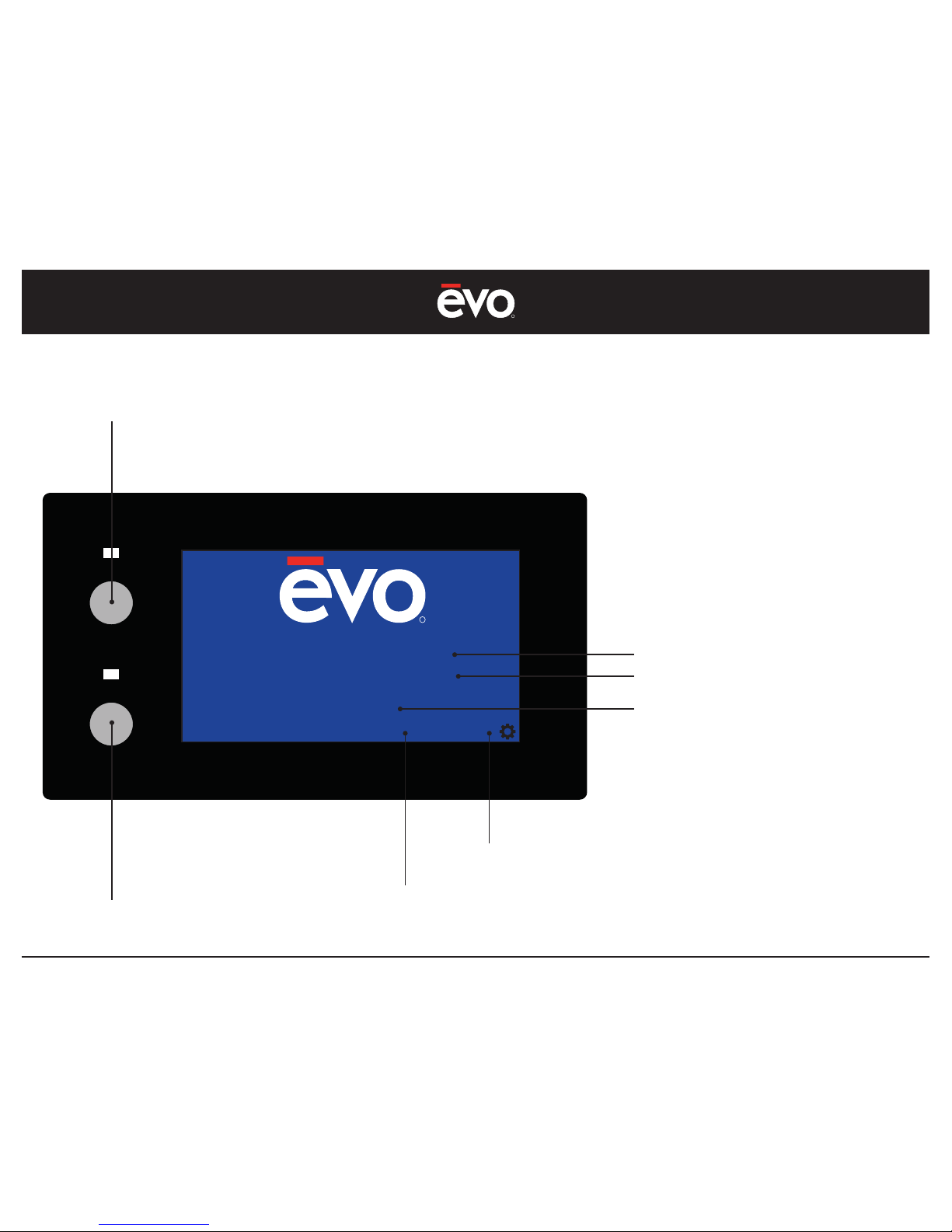
Status Screen
Main Control ON/OFF Button
Green ON Light
Cooktop Control ON/OFF Button
Blue ON Light
Administration Settings Select
Cooktop Surface Temperature Condition
System Version
Model Name
Evo, Inc. Contact Detail
Figure 1
CONTROL PANEL
Page 11
R
EVent 48E
11
ON / OFF
COOK
www.evoamerica.com
COLD SURFACE
VENTILATION STARTUP
Aperture Inlet
OK
Pre-Filter
OK
Crumb Drawer
OK
Charcoal Filter
OK
Grease Filter
OK
ESP Filter
OK
Grease Drawer
OK
Inlet Pressure
OK
COOKTOP STATUS
Preset 3
450F
ON
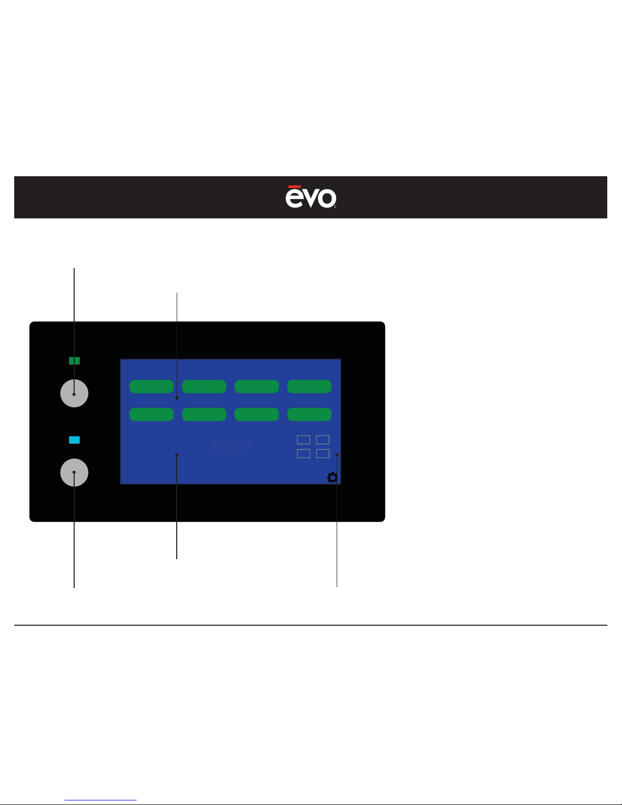
Main Control Button - ON - Light Green
Function #1
Temperature Control Muted - OFF
Function #4
Cooktop Control Button - Light OFF
Function #3
FUNCTIONS
#1 When the ON button is pressed, the light
shows green to indicate unit is ON. The
EVent unit performs a Ventilation System
Check and confi rms the unit is ready for
operation
#2 The Ventilation System Check confi rms
all critical ventilation components are
functioning correct - OK.
#3 Cooktop is disabled until ventilation
component check confi rms all critical
ventilation components are functioning
correct - OK.
#4 Cooktop temperature control is disabled
with muted color until COOK button is
pressed and COOK light shows blue.
#5 Heater indicator is disabled with muted
color until COOK button is pressed and
COOK light shows blue.
Ventilation Switch Check
Function #2
Heater Indicator
Function #5
Startup Screen
Figure 2
CONTROL PANEL
Page 12
R
EVent 48E
12
ON / OFF
COOK
www.evoamerica.com
COLD SURFACE
VENTILATION STARTUP
Aperture Inlet
OK
Pre-Filter
OK
Crumb Drawer
OK
Charcoal Filter
OK
Grease Filter
OK
ESP Filter
OK
Grease Drawer
OK
Inlet Pressure
OK
COOKTOP STATUS
Preset 3
450F
ON
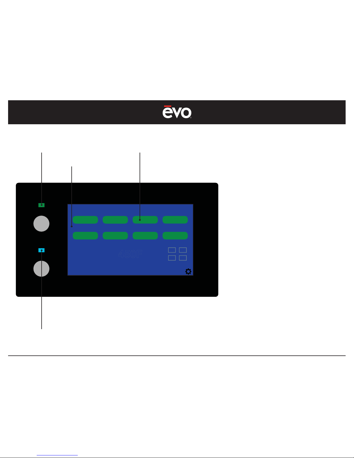
Main Control - ON
Function #1
Cooktop Control - OFF
Ventilation Switches
Function #2
Ventilation Startup
Figure 3
FUNCTION
#1 For Ventilation System Startup, select Main
Control to the ON position.
#2 The ventilation system will startup and
check 8 ventilation components.
#3 Each ventilation component will indicate
OK in green when the ventilation system is
functioning correct.
NOTE:
There are 8 ventilation component checks
performed before the EVent system will power
ON.
Each ventilation component relates to
an electrical switch that determines if a
component is functioning correct.
The following is a list of Ventilation Startup
Switch Components:
1 - Aperture Inlet
2 - Crumb Drawer
3 - Grease Filter
4 - Grease Drawer
5 - Pre-Filter
6 - Charcoal Filter
7 - ESP Filter
8 - Inlet Pressure
Ventilation Switch Check - OK
Function #3
CONTROL PANEL
Page 13
R
EVent 48E
13
ON / OFF
COOK
www.evoamerica.com
COLD SURFACE
VENTILATION STARTUP
Aperture Inlet
OK
Pre-Filter
OK
Crumb Drawer
OK
Charcoal Filter
OK
Grease Filter
OK
ESP Filter
OK
Grease Drawer
OK
Inlet Pressure
OK
COOKTOP STATUS
Preset 3
450F
ON
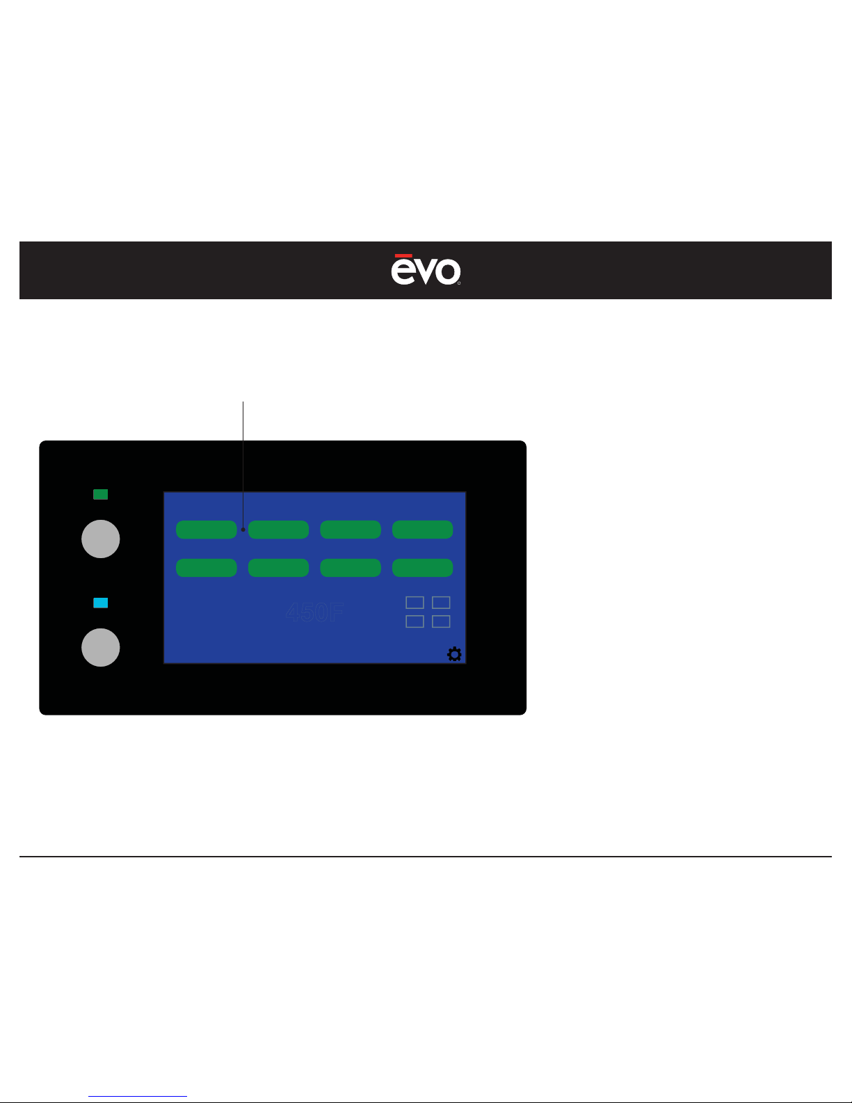
Ventilation Startup - FAULT
FUNCTION
#1 If a ventilation switch component is not
functioning correctly, a red FAULT warning
is shown next to the switch component
name.
To view corrective information about the
fault, press the FAULT button to view the
related Service Instruction.
NOTE:
During EVent unit operation, if any ventilation
startup switch component is not functioning
correctly, a fault will occur and the ventilation
fan will automatically shut down.
To restart the system, once the fault is cleared,
cycle the power OFF/ON.
For a list of ventilation switch component
faults and related service instructions, refer to
Appendix 1.
Ventilation Startup - FAULT
Function #1
Figure 4
CONTROL PANEL
Page 14
R
EVent 48E
14
ON / OFF
COOK
www.evoamerica.com
COLD SURFACE
VENTILATION STARTUP
Aperture Inlet
OK
Pre-Filter
OK
Crumb Drawer
GO BACK
Charcoal Filter
OK
Grease Filter
OK
ESP Filter
OK
Grease Drawer
OK
Inlet Pressure
OK
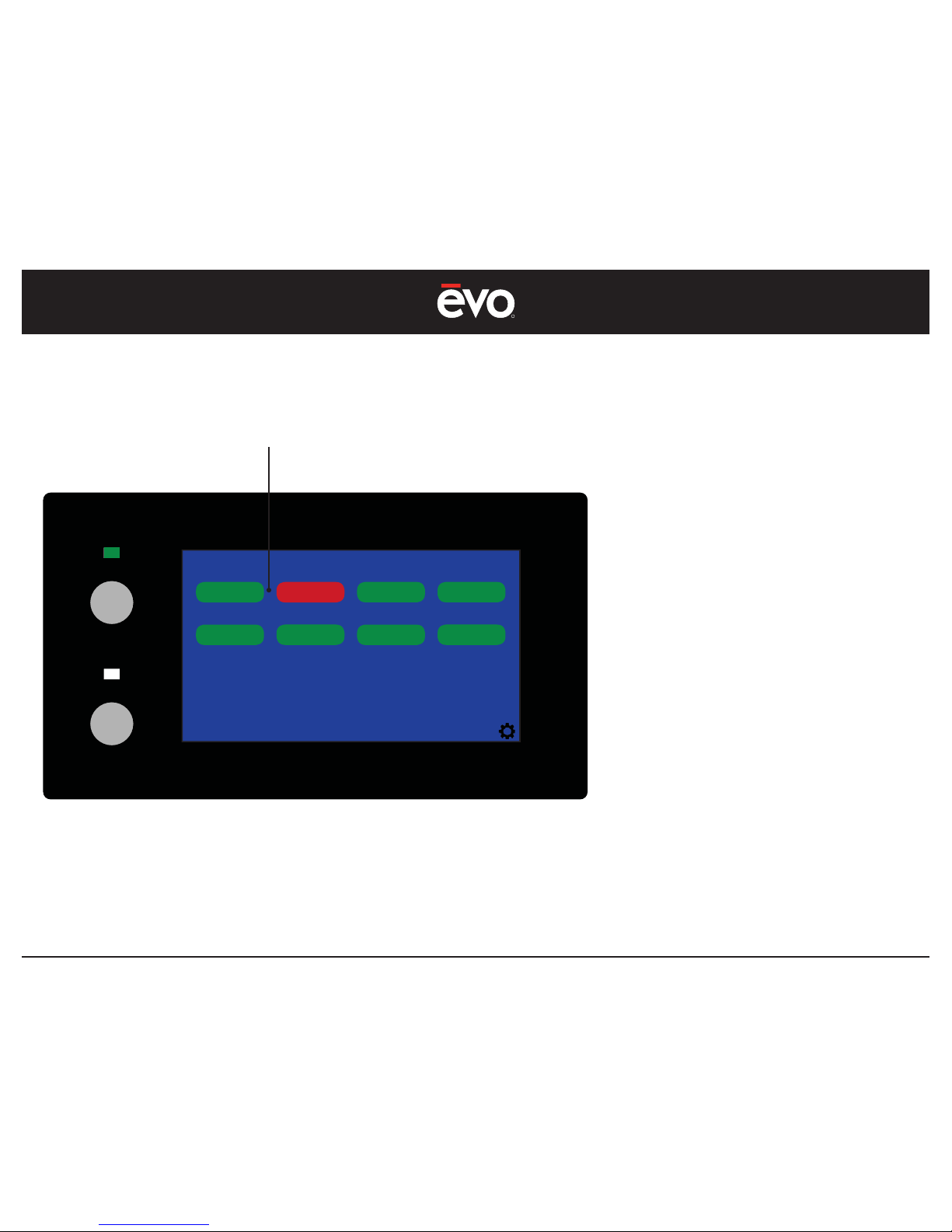
SERVICE INSTRUCTION - FAULT #2
Remove crumb drawer, clean switch contact area and reinsert drawer.
Cycle power to restart. If issue continues, call for repair
Ventilation Startup - FAULT Service Instruction
FUNCTION
#1 When the FAULT button is pressed, a
Service Instruction is shown that provides
information to correct the fault. Once this
information is read, press the GO BACK
button to return to the previous screen.
NOTE:
If more than one FAULT occurs, select each
FAULT to view the Service Instruction. Press
the GO BACK button to return to the previous
menu.
To restart unit, once th fault is cleared, cycle
the power OFF/ON.
For a list of ventilation faults and
related service instructions,
refer to Appendix 1.
Ventilation FAULT - Service Instruction
Function #1
Figure 5
CONTROL PANEL
Page 15
R
EVent 48E
15
ON / OFF
COOK
www.evoamerica.com
HOT SURFACE
VENTILATION STARTUP
Aperture Inlet
OK
Pre-Filter
OK
Crumb Drawer
OK
Charcoal Filter
OK
Grease Filter
OK
ESP Filter
OK
Grease Drawer
OK
Inlet Pressure
OK
COOKTOP STATUS
Preset 3
450F
450F
ON
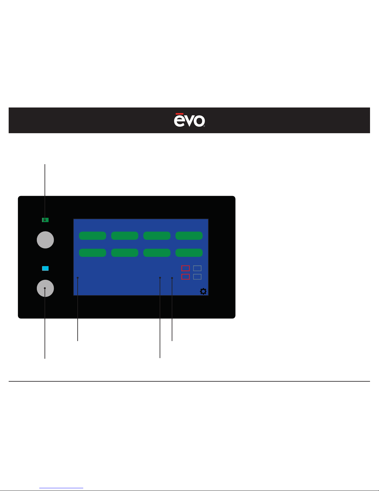
FUNCTIONS
#1 With ON/OFF button in ON position and
the ventilation startup switch components
showing OK, the COOK button becomes
operational.
#2 When the COOK button is pressed to the
ON position, the light shows blue.
#3 Cooktop Status temperature control
becomes functional, and ON indicator
shows green.
#4 Temperature Presets are controlled from
the Settings screen (see Set Temperature
Preset Figure 9
). The last preset confi gured
under Settings will remain the default until
changed.
#5 Heater Indicator Block shows active
heaters in red outline (see note below).
NOTE:
The EVent 48E has 4 electric heaters positioned
under the cooking surface represented by
the Heater Indicator Block. An active heater
is represented by red color block. Using
intelligent heater control to maintain a set
temperature, the system only energizes an
area of the cooking surface that requires heat,
leaving the other heaters idle to conserve
energy.
Main Control Button - ON - Green Light
Function #1
Cooktop Control Button - ON
Function #2
Temperature Control - ON
Function #3
Heater Indicator Block
Function #5
Cooktop Startup
Preset Temperature Indicator
Function #4
Figure 6
CONTROL PANEL
Page 16
R
EVent 48E
16
ON / OFF
COOK
www.evoamerica.com
COLD SURFACE
ADMIN SETTINGS
OPTIONAL
OPTIONAL
OPTIONAL
FACTORY SETTINGS
HOME
SET TEMPERA TURE
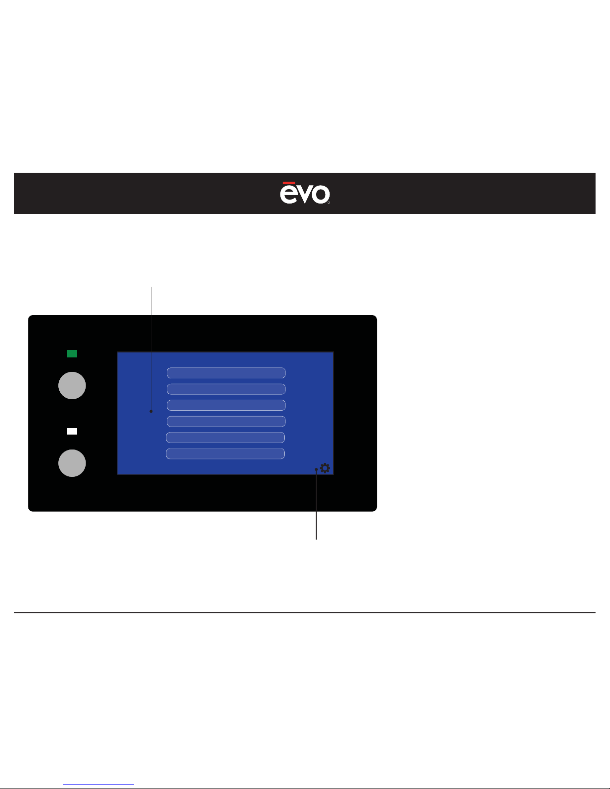
FUNCTION
#1 To select the Administration Settings, press
the gear icon in the lower right screen.
Choosing a feature jumps you to the
related setup screen.
Figure 8
Settings Selection
Function #1
Administration Settings Select
Administration Settings - Overview
CONTROL PANEL
Page 17
R
EVent 48E
17
ON / OFF
COOK
www.evoamerica.com
COLD SURFACE
SELECT TEMPERATURE PRESET
PRESET 2 PRESET 3 MANUALPRESET 1
PRESET 1
225F
HOME
Administration Settings - Select Temperature Presets
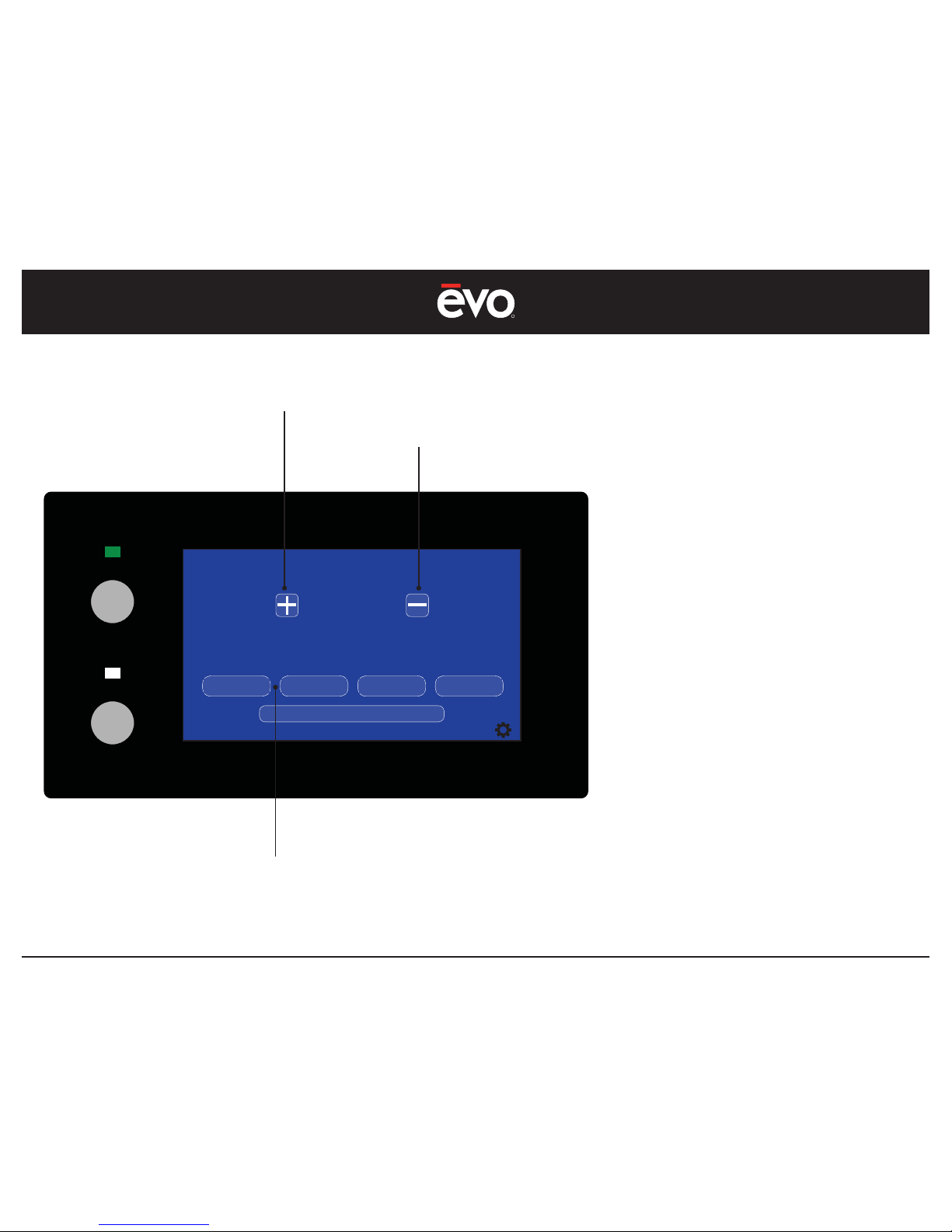
FUNCTION
#1 Select a temperature preset.
#1 To increase temperature select the
“+”
button.
#2 To decrease temperature select the
“-”
button.
NOTE:
Previously selected temperature presets are
stored in memory and recalled by pressing the
respective preset button.
To change a preset, select a preset number
and increase or decrease the temperature
setting.
Temperature selections are available in
increments of 25F (4C) from 150˚F to 525˚F
(65˚C to 288˚C).
Figure 9
Increase Temperature
Function #2
Decrease Temperature
Function #3
Select Temperature Presets
or choose Manual mode
Function #1
CONTROL PANEL
Page 18
R
EVent 48E
18
ON / OFF
COOK
www.evoamerica.com
COLD SURFACE
VENTILATION STARTUP
Aperture Inlet
OK
Pre-Filter
OK
Crumb Drawer
OK
Charcoal Filter
OK
Grease Filter
OK
ESP Filter
OK
Grease Drawer
OK
Inlet Pressure
OK
COOKTOP STATUS
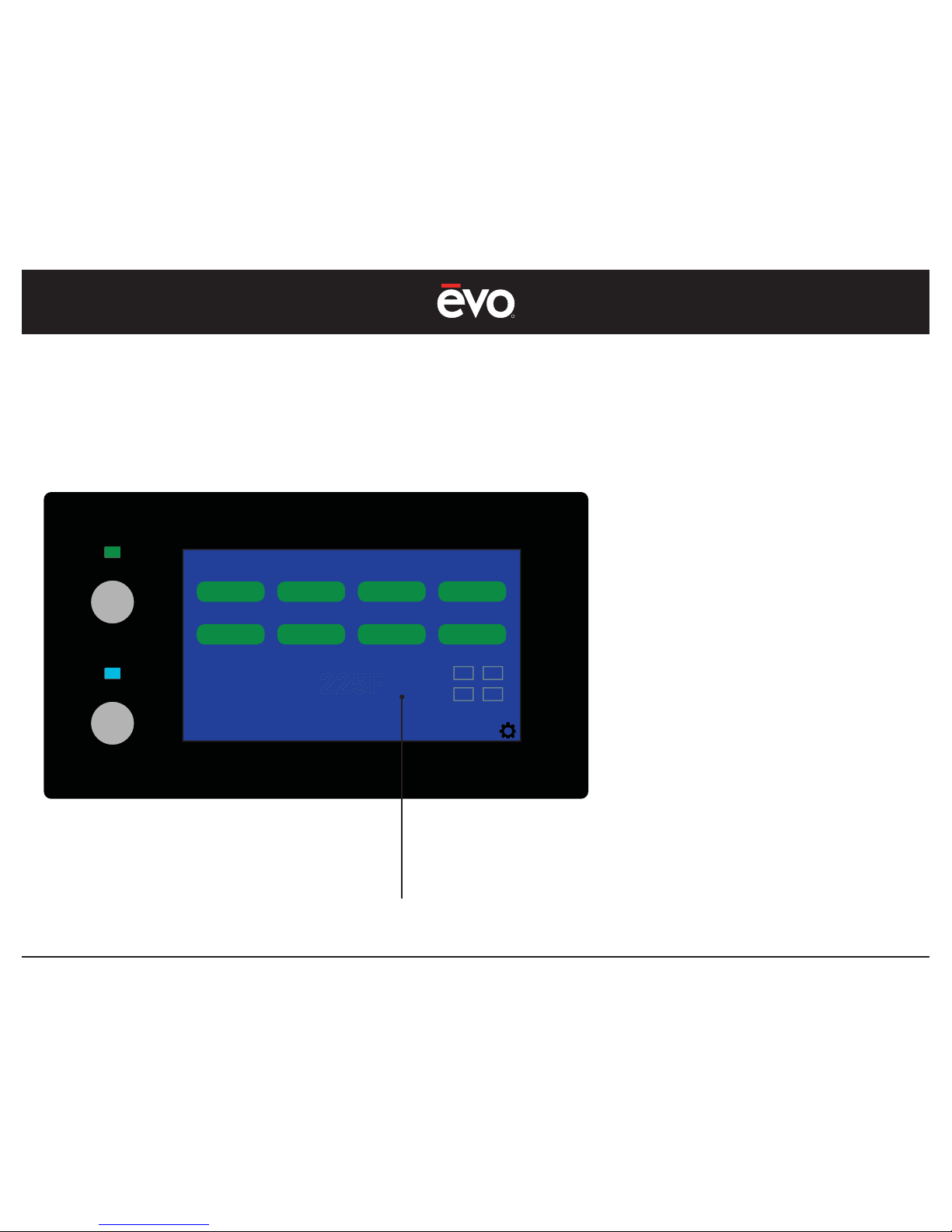
Preset 1
225F
ON
FUNCTIONS
#1 A temperature preset will become
available under Cooktop Status once it is
selected from the Set Temperature Preset
screen (see Figure 9).
NOTE:
The last preset confi gured under Settings will
remain the default preset value until a new
temperature preset is selected or until manual
mode is selected.
Administration Settings - Select Temperature Presets
Preset Temperature Indicator
Function #1
Figure 10
CONTROL PANEL
Page 19
R
EVent 48E
19
ON / OFF
COOK
www.evoamerica.com
HOT SURFACE
VENTILATION STARTUP
Aperture Inlet
OK
Pre-Filter
OK
Crumb Drawer
OK
Charcoal Filter
OK
Grease Filter
OK
ESP Filter
OK
Grease Drawer
OK
Inlet Pressure
OK
COOKTOP STATUS
ON
MANUAL
350F
User Settings - Use Manual Temperature
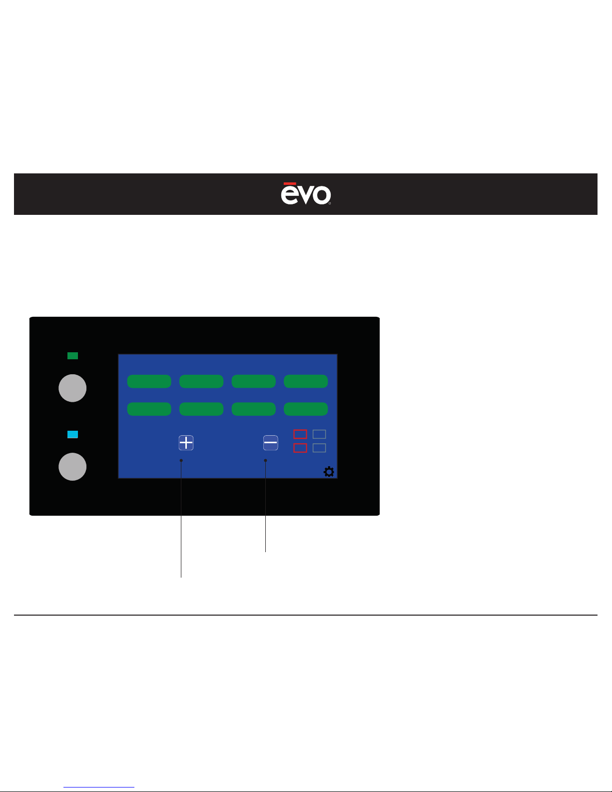
FUNCTIONS
To set temperature manually, select
Manual Temperature mode from the Select
Temperature Preset screen (see Figure 9).
Once manual temperature is selected
under Settings it shows green and the screen
reverts to the Startup screen showing manual
temperature control.
#1 To increase temperature press the “ + “
button.
#2 To decrease temperature press the “ - “
button.
NOTE:
If manual temperature is the last selected
control temperature under Settings, then
it will remain the default value until a new
temperature is selected.
Temperature - Decrease
Function #2
Temperature - Increase
Function #1
Figure 11
CONTROL PANEL
Page 20
R
EVent 48E
20
ON / OFF
COOK
www.evoamerica.com
COLD SURFACE
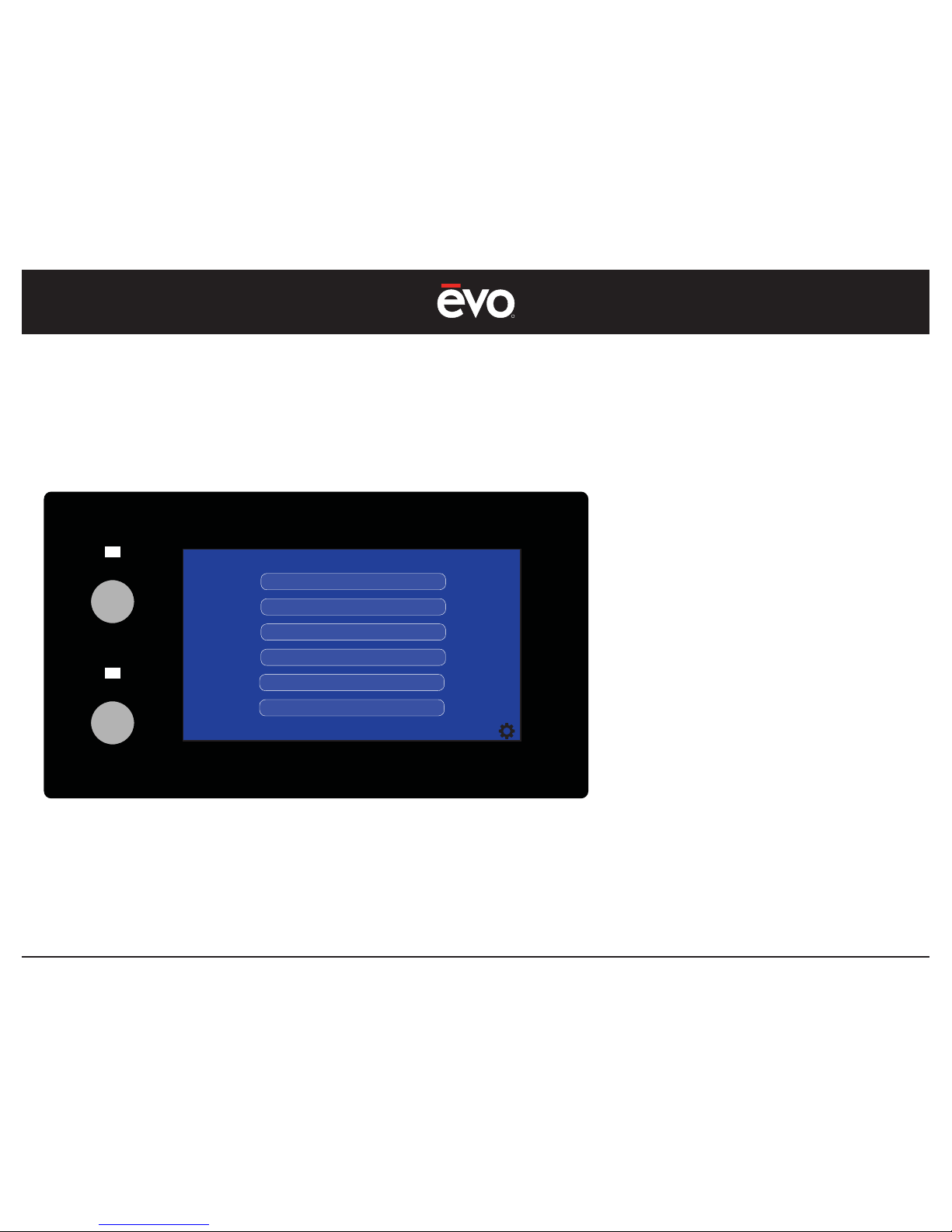
FACTORY SETTINGS
TEMPERATURE ACTUAL
TEMPERATURE OFFSETS
OPTIONAL
OPTIONAL
OPTIONAL
HOME
Factory Settings - Overview
FUNCTION
The factory settings control screen provides
factory utilities for adjusting the setup
parameters of the EVent 48E system.
NOTE:
These parameters are set at the factory and
do not require adjustment. Only authorized
factory service technicians should access
these utilities.
Figure 13
CONTROL PANEL
Page 21
R
EVent 48E
21
ON / OFF
COOK
www.evoamerica.com
COLD SURFACE
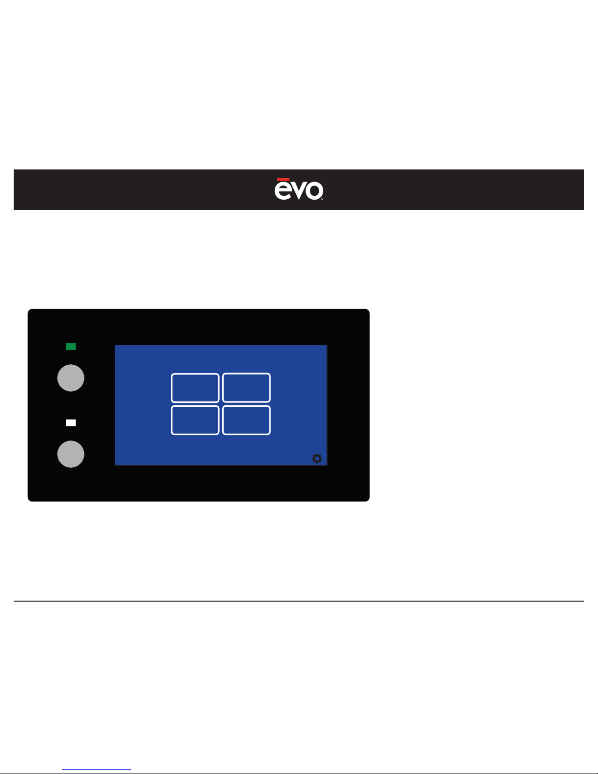
ACTUAL TEMPERATURE
100 F
1
100 F
3
100 F
2
100 F
4
Factory Settings - Actual Temperature
FUNCTION
The actual temperature screen shows actual
temperature at each heater zone location
which also includes the offset value.
The factory setting allows accurate calibration
of the actual cooking surface temperature to
the calculated electrical heater temperature
positioned under the cooking surface.
Only authorized factory service technicians
should use this utility to calibrate cooking
surface temperature.
Figure 14
CONTROL PANEL
Page 22
R
EVent 48E
22
ON / OFF
COOK
www.evoamerica.com
COLD SURFACE
SELECT TEMPERATURE OFFSETS
20F
ZONE 1 ZONE 3
ZONE 2 ZONE 4
Factory Settings - Set Temperature Offsets
FUNCTION
The temperature offset screen shows the
offset temperature at each heater zone, and
provides individual adjustment of each zone.
This factory setting allows calibration of the
temperature carry-over calculation that
provides accurate actual cooking surface
temperatures.
Only authorized factory service technicians
should use this utility to calibrate cooking
surface temperature.
Figure 15
CONTROL PANEL
Page 23
R
EVent 48E
23
MAINTENANCE
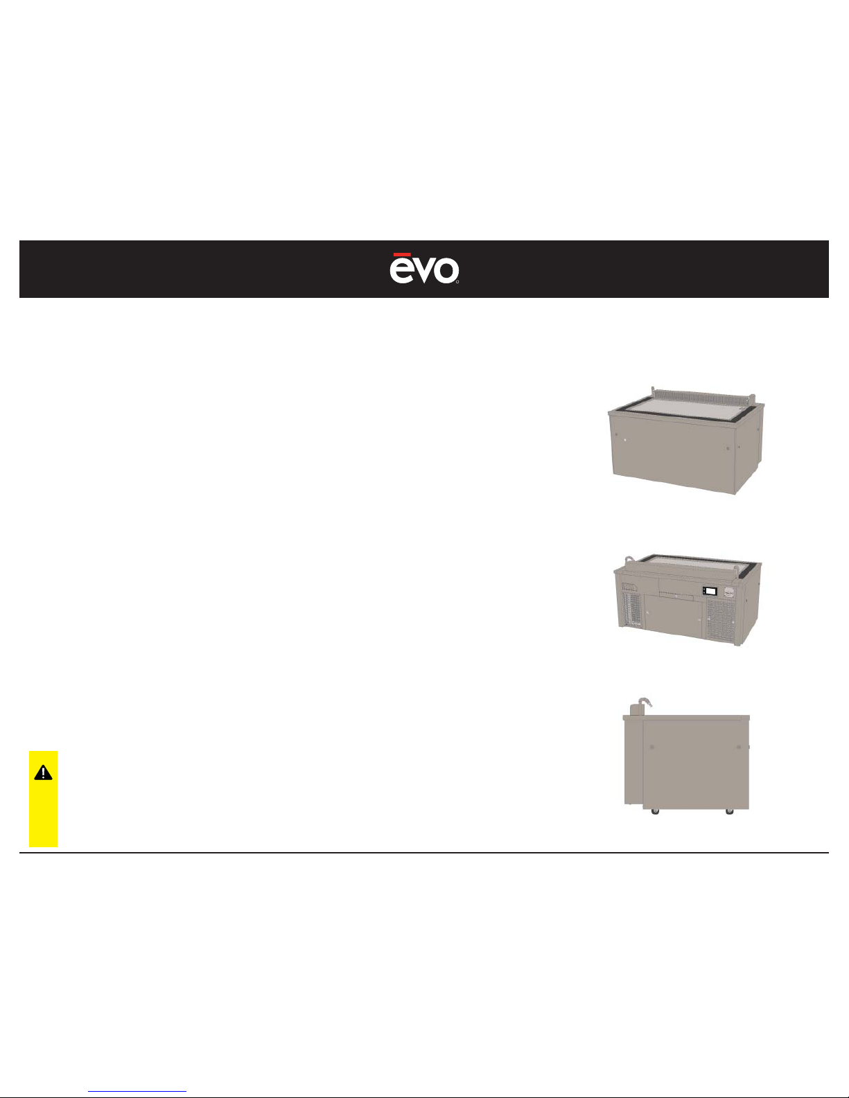
Cleaning - Stainless Steel Chef-Side Panels and Toe Kick Panels
Turn Off Power Before Cleaning
Establish a regular cleaning schedule. Any spills should be wiped off
immediately.
1. Wipe exposed, cleanable stainless steel surfaces when cool with
a mild detergent and warm water. Stubborn residue spots should
be soaked with warm soapy water and rubbed clean with a terry
cloth or paper towel. Dry thoroughly with a clean cloth.
2. Always rub stainless steel in the direction of the metal grain to
prevent scratching. Use a stainless steel cleaner if you want a high
shine. Never use abrasive scour pads or steel wool on stainless
steel.
3. The control panel surface is made from a plastic material and
requires more delicate cleaning. Use warm soap and water and a
soft cloth. Do not use abrasive scour pads or solvent cleaners since
these will scratch or cloud the surface.
4. Never spray the perforated areas or control panel with steam or
water, this will allow moisture into the control cavity which could
damage electrical components.
Always use non-abrasive cleaner
when cleaning stainless steel
panels to avoid scratching and
dulling the surfaces. Never use
steel wool on stainless steel.
Page 24
R
EVent 48E
24
MAINTENANCE
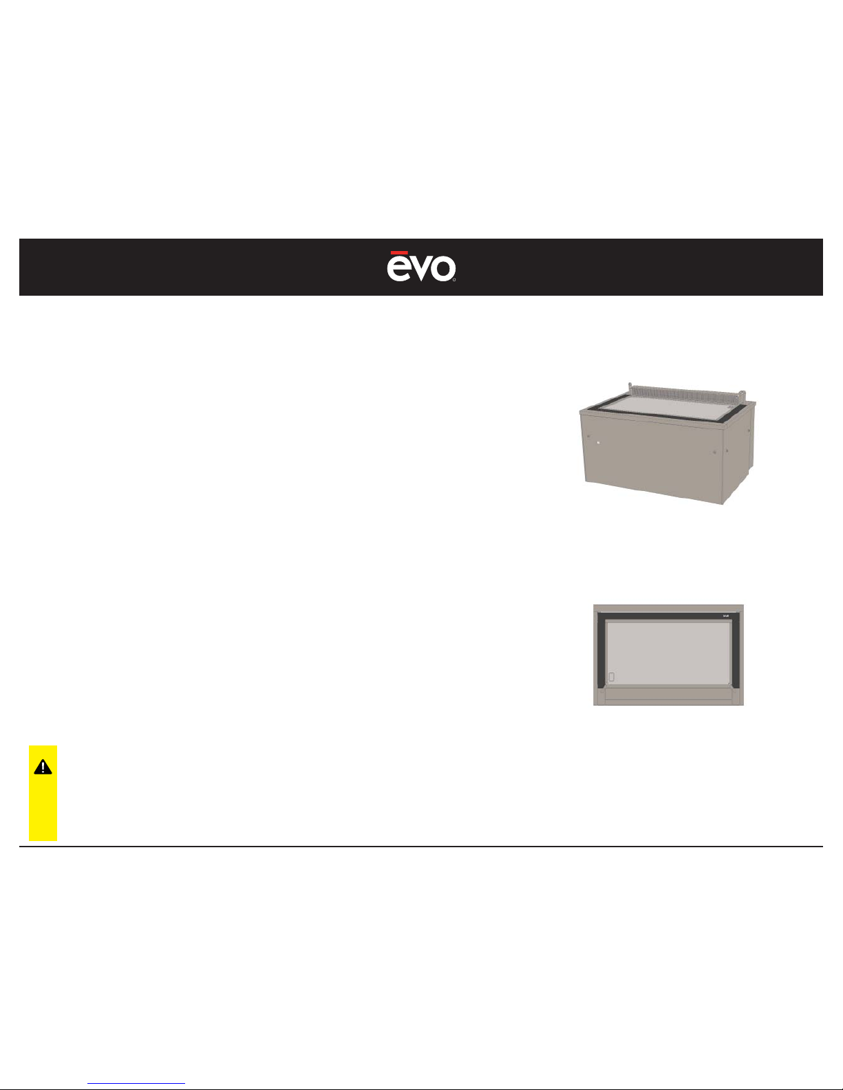
Cleaning - Decorative Tabletop, Side Panels, and Granite Surfaces
Turn Off Power Before Cleaning
Establish a regular cleaning schedule. Any spills should be wiped off
immediately.
1. Using a terry cloth or paper towel, wipe the seating area and
under counter side panels with warm soap and water, or a mild
detergent suitable for the particular fi nish used on your EVent®
teppanyaki table. In general, never use abrasive scour pads or
corrosive cleaners as these will dull or destroy the fi nish of most
decorative tabletop and side panel materials.
2. To maintain the granite surfaces surrounding the cooking griddle,
use a terry cloth or paper towel with warm soap and water or a
mild detergent.
3. To achieve a high luster fi nish on the granite surfaces, fi rst remove
heavy soil with warm soap and water, followed by a glass cleaner
such as Windex
©
or a solution of water and vinegar.
Always use a non-abrasive cleaner
when cleaning decorative
surfaces including the seating
area and side panels to avoid
scratching, dulling or damaging
the surfaces.
Page 25
R
EVent 48E
25
Cleaning - The Griddle Surface
Turn Off Power Before Cleaning
MAINTENANCE
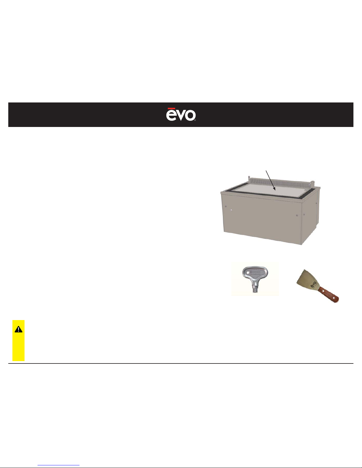
There are several methods for cleaning the griddle cooking surface.
The following guidelines are offered as a ‘best practice’ method for
the EVent® 48E cooking surface.
CAUTION: Do not pour water onto
hot griddle surface when the
ventilation fan system is on. The
water vapor will be pulled into the
vent aperture and will degrade
and/or damage the ESP unit.
1. Press the COOK button on the Control Panel to turn off the
cooking surface. The blue LED indicator light will be off.
2. Press the OFF button on the Control Panel to turn off the
ventilation system. The green LED indicator light will be off.
3. Using a scraper or spatula, scrape and remove loose debris by
sweeping into the spillover slot.
4. While the cooking surface is still warm, scrub the surface with a
grill pad in a circular motion, using a grill pad holder to maintain
even pressure on the pad.
5. For heavy carbon buildup, it may be necessary to use a grill
screen in combination with the grill pad.
6. Thoroughly wipe the surface with a terrycloth towel to remove
any debris from the grill pad and grill screen.
7. Apply a thin layer of vegetable oil over the entire surface with
a clean cloth to condition the steel surface and help prevent
rusting.
SEE APPENDIX 2 FOR DETAILED GRIDDLE SURFACE CLEANING INSTRUCTIONS
Steel Griddle
Cooking Surface
Cleaning handle,
Pad and screen.
Scraper
Page 26
R
EVent 48E
26
MAINTENANCE
Cleaning - Ventilation Inlet Aperture
Turn Off Power Before Cleaning
The Ventilation Aperture is located on the chef-side of the EVent®
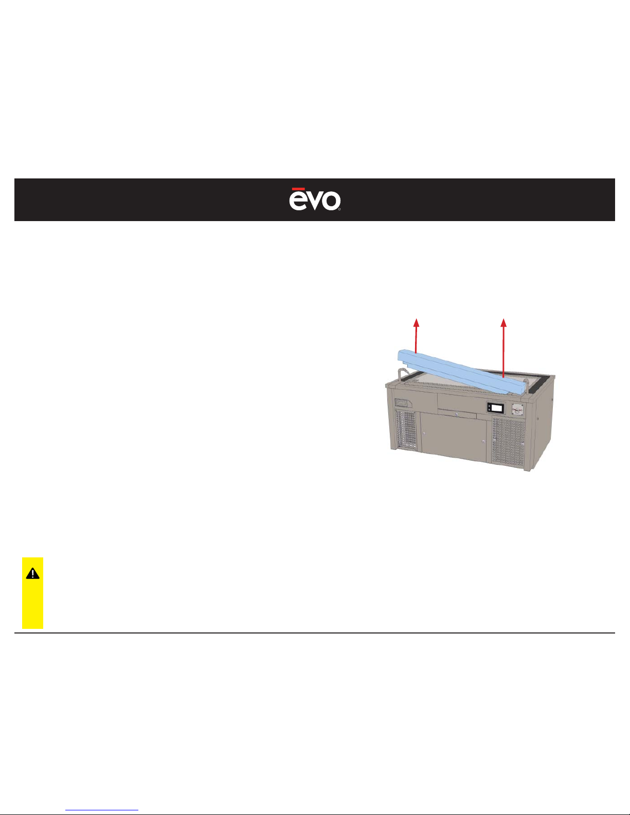
48E, and is removable for easy cleaning.
Depending on the amount and type of foods being cooked, daily
cleaning may be required.
CAUTION: When cleaning inlet
duct, do not disrupt, fl ex or bend
the fi re suppression fusible link
or the fi re suppression system.
Failure may cause a discharge,
damaging the unit and voiding
the EVent® 48E warranty.
1. Using two hands, pull the aperture out of the inlet duct slot.
2. Clean the aperture with warm soap and water or a non-corrosive
detergent. A good method is to place the aperture over a 3-bin
sink to wash, then rinse and dry throughly.
3. IMPORTANT - Read the following page titled, “Cleaning -
Ventilation Inlet Duct” before attempting to clean the duct
under the aperture.
Page 27
R
EVent 48E
27
MAINTENANCE
Cleaning - Ventilation Inlet Duct
Turn Off Power Before Cleaning
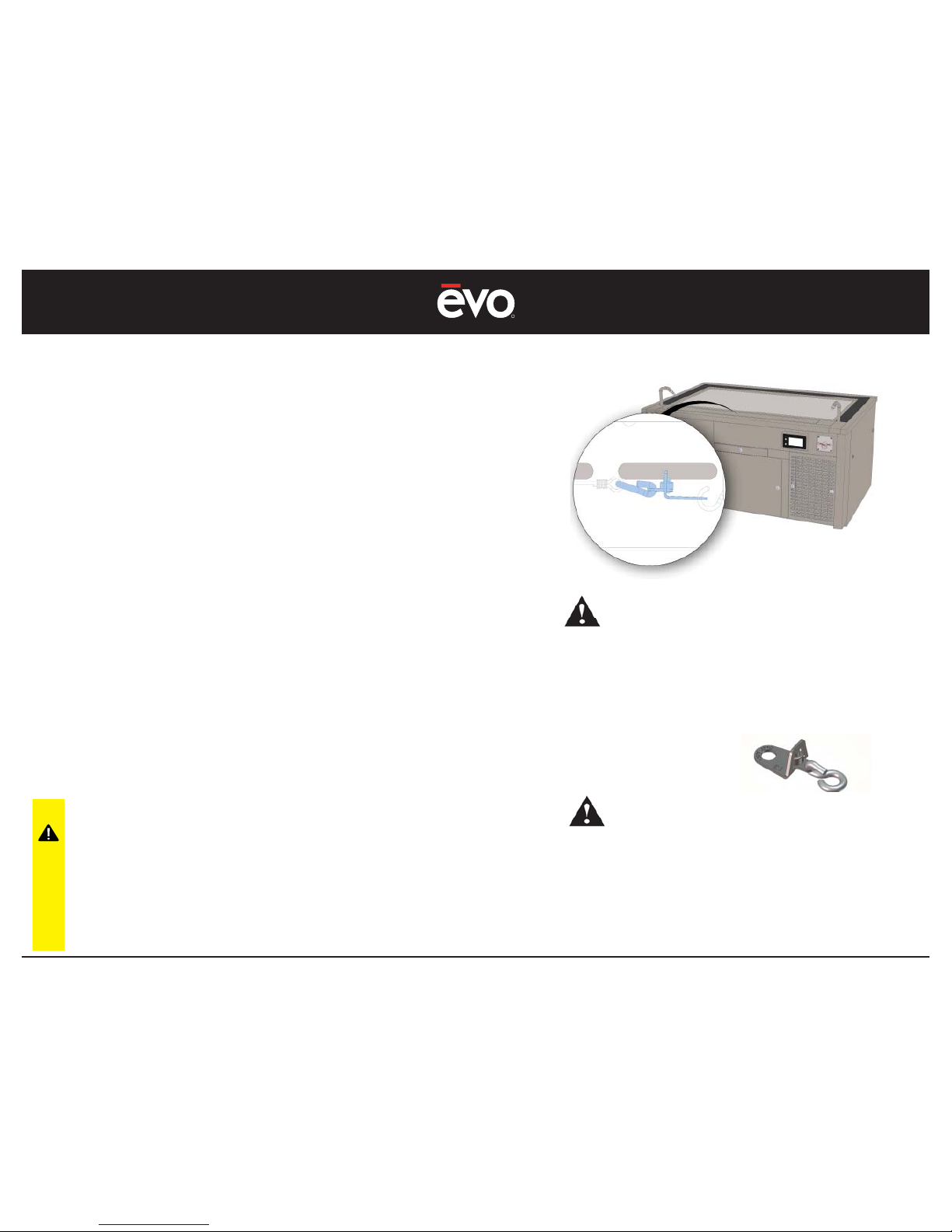
Within the Ventilation Inlet Duct is the fi re suppression fusible link that
engages the fi re suppression system. If there is fi re on the cooking
surface and the fi re enters the inlet aperture, the fusible link is
designed to melt at temperatures above 280˚F and discharge the
fi re suppression system.
CAUTION: Never use steam cleaning
equipment to clean the EVent® unit.
Never use excessive amounts of water
or ice for cleaning the cooking surface.
Doing do will cause steam to enter the
inlet aperture and disrupt the fusible link
which may discharge the fi re suppression
system causing damage and voiding the
EVent® 48E warranty.
1. Remove the ventilation inlet duct aperture and inspect the inlet
duct for grease and food debris. Inside the inlet aperture is the
fi re suppression fusible link assembly (see Illustration 1 & 2).
2. Clean the aperture with standard soap and water or a non-
corrosive detergent. Using paper towels or a terry cloth towel,
wipe all grease and food debris clean from the inlet duct.
3. Use extreme caution and do not disrupt the fusible link located
inside the ventilation inlet duct. Gently clean the fusible link and
link wire cable using moist towels or a fi nely textured brush.
4. Do not use rigid tools for cleaning the inlet duct and do not chip
or scrape around the fusible link assembly. Doing so may cause
the fi re suppression system to discharge.
CAUTION: Never use steam cleaning equipment
to clean the ventilation inlet duct. Never use
excessive amounts of water or ice for cleaning the
cooking surface. Doing so will cause steam to enter
the inlet aperture and the fi re suppression fusible
link will become damaged resulting in a discharge
of the fi re suppression system causing damage and
voiding the warranty.
CAUTION: The fusible link is installed under
tension to a wire cable that engages the fi re
suppression system. The link is designed to melt at
a temperature of 280˚F which will release tension
to the wire cable and trigger the fi re system.
Never use steam cleaning equipment or deglaze
the cooking surface with water, or use corrosive
cleaners to clean ventilation inlet duct as this will
cause damage to the fusible link resulting in a
discharge of the fi re system.
Illustration 2
Illustration 1
Page 28
R
EVent 48E
28
MAINTENANCE
Cleaning - The Crumb Drawer
Turn Off Power Before Cleaning
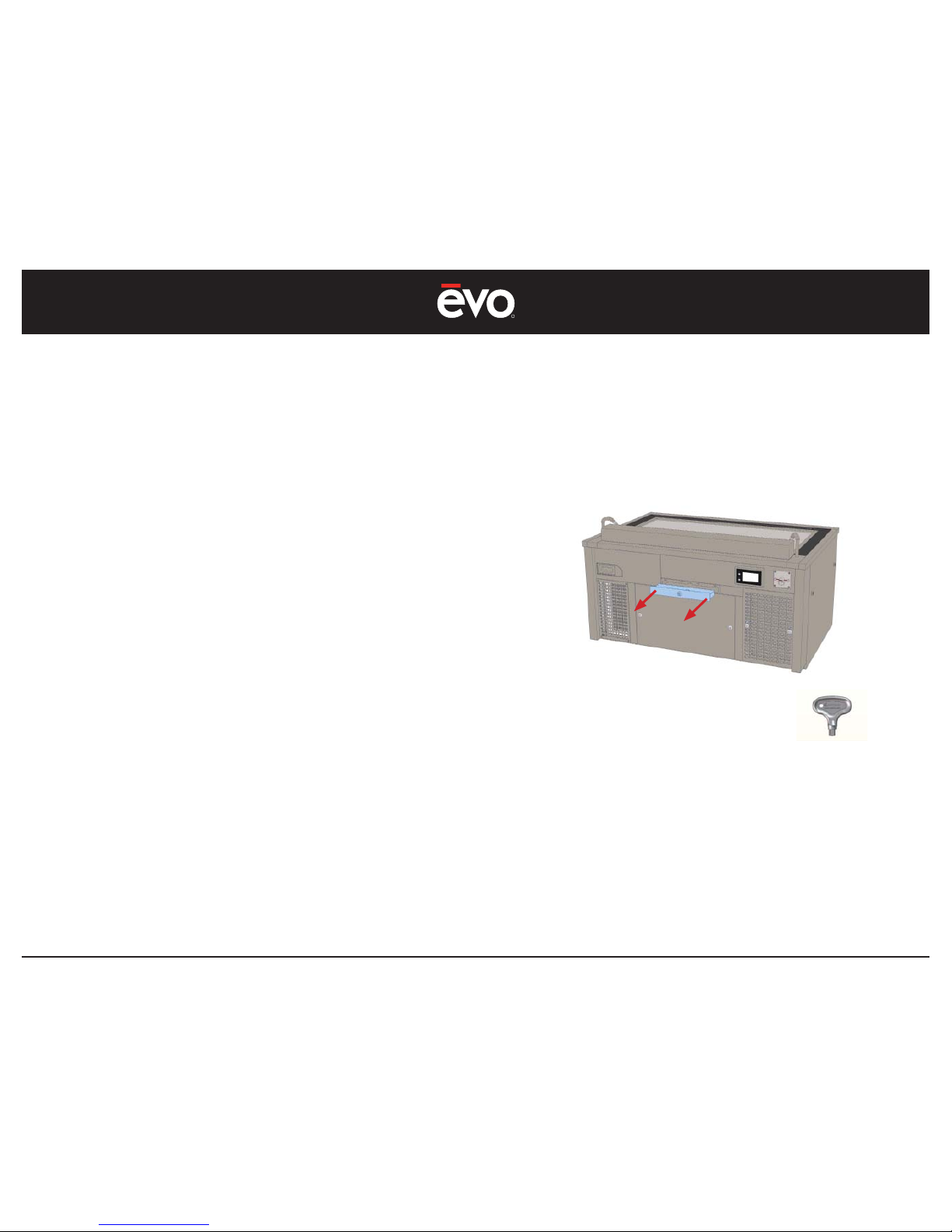
The Crumb Drawer is secured by a hex key and located on the chefside just below the aperture. It is designed to collect some of the
food and grease debris that is pulled into the aperture. Under normal
cooking conditions, the crumb drawer should be washed weekly.
Depending on the food being cooked or the frequency of cooking,
you may extend cleaning cycles beyond one week to every other
week.
1. Using the supplied Hex Key, unlock the crumb drawer and pull
forward to remove.
2. Clean the crumb drawer with standard soap and water or a
non-corrosive detergent. For fast cleaning, wash the drawer in a
commercial dish washing machine. Wash as necessary to remove
all grease buildup.
3. Reinsert the clean and dry crumb drawer and make sure the
drawer makes contact with the plunger switches on the back
wall of the aperture duct. You will notice a slight ‘click’ when the
drawer is reinserted and makes contact with the switches.
THE CRUMB DRAWER LATCH ENGAGES A SLOT IN THE BOTTOM OF THE
APERTURE DUCT. TO ENSURE THE LATCH IS LOCKING PROPERLY,
LOOK INTO THE BOTTOM OF THE APERTURE DUCT AND MAKE SURE
THE LATCH IS ENGAGING THE APERTURE DUCT SLOT
Hex Key 8mm
Page 29
R
EVent 48E
29
Cleaning - The Grease Filter
Turn Off Power Before Cleaning
The grease fi lter is a stainless steel baffl e fi lter that captures airborne
grease. Under routine cooking conditions, the grease fi lter should
be washed once a week or replaced with a clean standby fi lter as
necessary.
Depending on foods being cooked or the frequency of cooking, you
may extend cleaning cycles beyond once a week to every other
week.
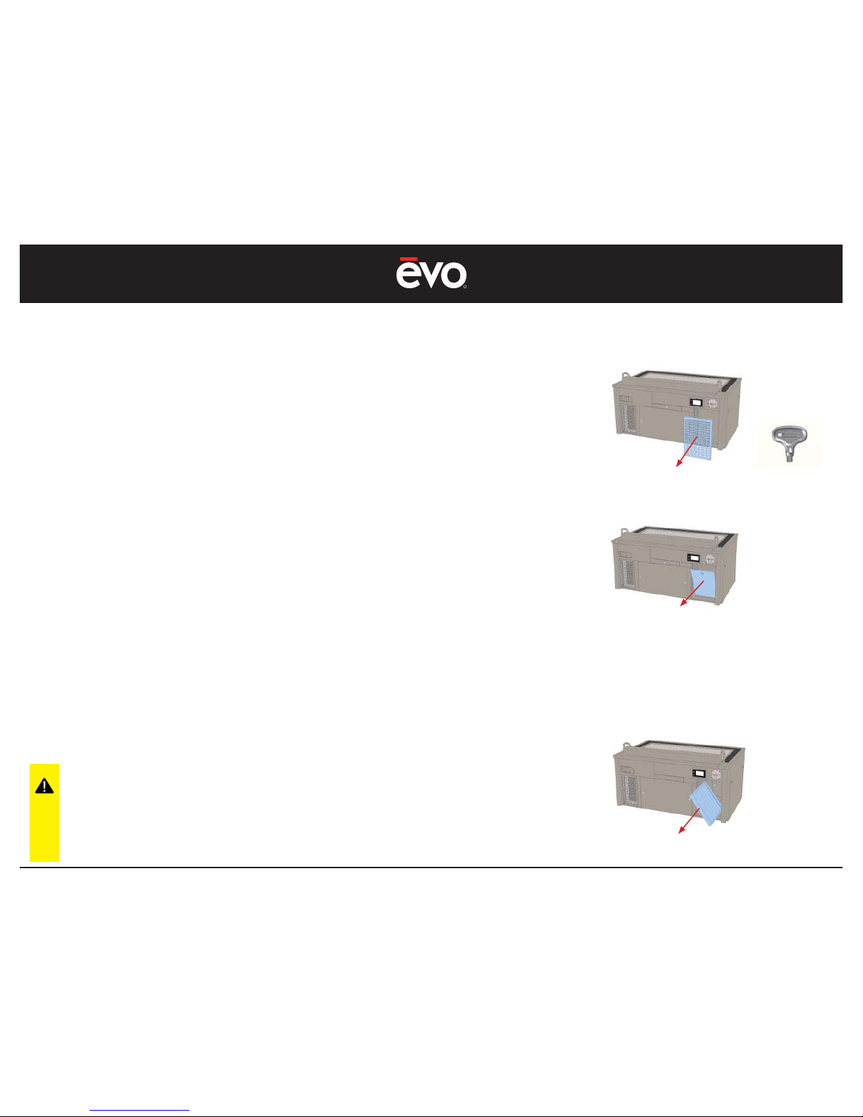
1. From the chef-side of the table, remove the right side perforated
panel by unlatching the middle latches using the 8mm Hex Key.
Set the perforated panel aside. Behind the perforated panel is the
door to the grease fi lter box. Unlatch the door using the 8mm Hex
Key. (see Illustration 1).
2. With the grease door unlatched, tilt the door outward and lift
upward to release the door from the bottom metal channel.
When the door is forward of the metal channel, again tilt the door
outward to remove the door. Set the door aside, and remove the
grease fi lter by pulling it forward. (see Illustration 2 & 3).
3. Clean the grease fi lter by soaking in a degreaser solution and
rinsing clean. For faster cleaning, wash the fi lter in a commercial
dish washing machine. Wash as necessary to remove all grease
buildup.
4. Throughly dry the grease fi lter before reinserting into the grease
fi lter enclosure. Alternatively, have an extra standby fi lter to
facilitate fast cleaning.
CAUTION: Use only the stainless
steel baffl e-type grease fi lter
supplied by Evo. Failure to do so
may cause damage to the ESP
unit and void the EVent® 48E
warranty.
MAINTENANCE
Note: With the grease door unlatched, tilt the
door outward and lift upward to lift the door
from the bottom metal channel. When the
door is forward of the metal channel, tilt the
door outward to remove.
Illustration 1
Hex Key 8mm
Illustration 2
DURING GREASE FILTER CLEANING,
ALSO CLEAN THE GREASE BOX
ENCLOSURE. SEE SECTION CALLED.
‘CLEANING - GREASE BOX ENCLOSURE’
Illustration 3
Page 30
R
EVent 48E
30
MAINTENANCE
Cleaning - The Grease Filter Enclosure Part 1
Turn Off Power Before Cleaning
With the grease fi lter removed from its enclosure, wipe the inside
of the enclosure and all duct surfaces to remove grease and food
particles.
For fast cleaning, use a non-corrosive, non-toxic spray degreaser
to wet the inside surfaces, then wipe clean using paper towels or a
terrycloth towel.
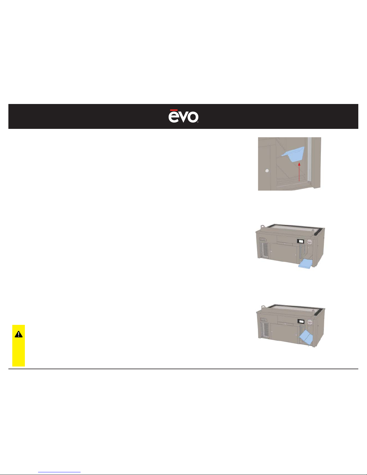
1. With the grease fi lter removed, remove the right-side support
bracket, grease fi lter slotted pan, and grease fi lter bottom
drawer for cleaning. Clean with a non-corrosive non-toxic spray
degreaser, or wash these parts in a commercial dish washing
machine.
2. Spray the inside surfaces of the grease enclosure and associated
connecting ducts with a non-corrosive non-toxic cleaner.
3. Wipe the enclosure and all duct surfaces free of grease and food
particles using paper towels or a terrycloth towel.
4. Throughly dry all surfaces and ensure there is no moisture or food
particles remaining in the enclosure or connecting ducts.
CAUTION: When cleaning the grease
fi lter enclosure, use care not to disrupt
the air tube or allow food particles to
enter the air tubes (do not wipe the end
of the air tube which may cause grease
debris to clog tube).
Step 1: Remove the support bracket, lifting from
the front and tilting upward. To reinsert, tilt the
bracket toward the rear and push down in the
front.
Step 3: With the bottom drawer removed, tilt the
slotted pan right and slide forward.
Step 2: Remove the bottom drawer from
underneath the slotted pan. Lift the slotted pan
and then remove the bottom drawer by lifting
and pulling forward.
Page 31
R
EVent 48E
31
MAINTENANCE
Cleaning - The Grease Filter Enclosure Part 2
Turn Off Power Before Cleaning
With the grease fi lter enclosure clean, make sure the grease fi lter,
support bracket, slotted pan, grease drawer, and door are clean
and ready for reassembly.
7. Reassemble the grease fi lter support bracket and grease fi lter
enclosure bottom pan the reverse of removal. Use special care
to insert each component and make sure there is no damage or
disruptions to the air tube.
8. Reinsert the grease drawer and make sure the drawer makes
contact with the plunger switches on the back wall of the
enclosure. You will notice a slight ‘click’ when the drawer is
reinserted into the enclosure and makes contact with the
switches.
9. Install a clean and dry grease fi lter and make sure the fi lter makes
contact with the two plunger switches on the back wall of the
enclosure.
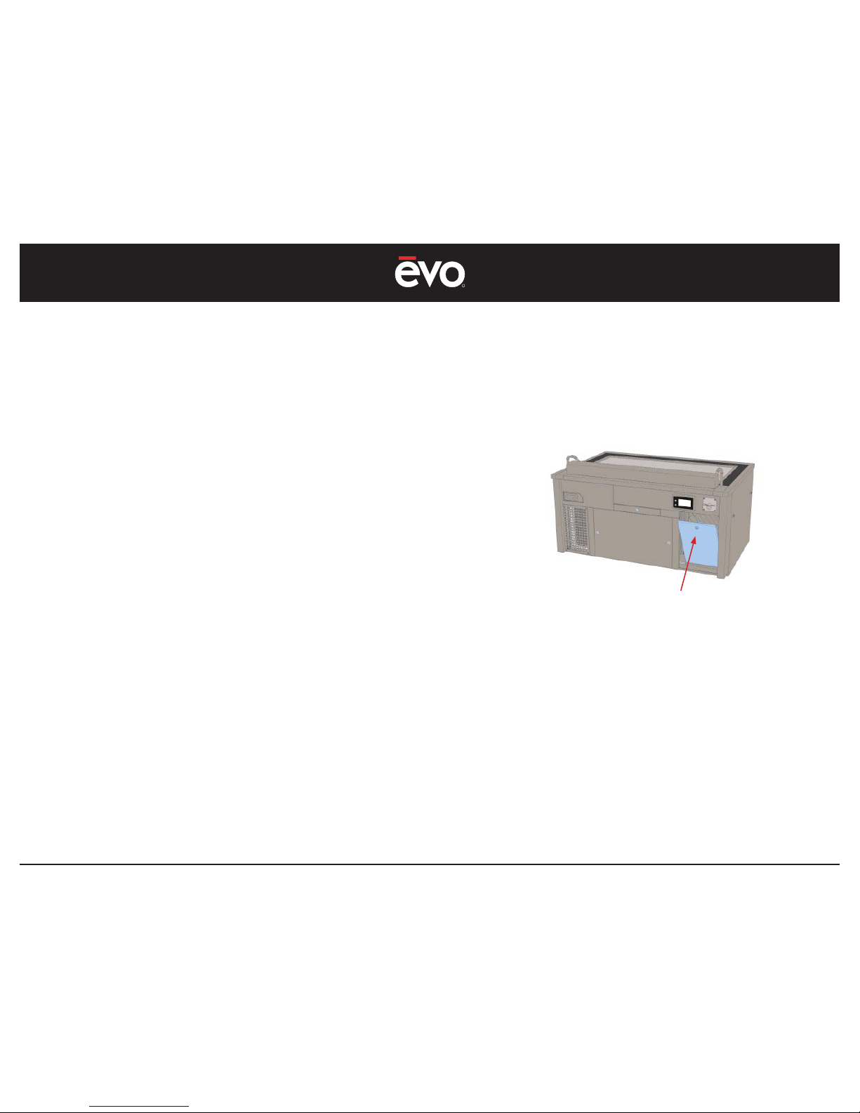
10. Reinsert the grease enclosure door by fi rst placing the door into
the bottom metal channel, then tilting the door forward into the
door frame. Using the 8mm hex key, turn the latch to secure the
door into the door frame.
11. Reinstall the perforated exterior panel. Using the 8mm hex key,
turn both lathes and secure the panel into place.
Note: To reinsert the grease door, fi rst place the
door into the bottom metal channel, then tilt the
door forward into the door frame. Using the 8mm
hex key, turn the latch to secure the door into
the door frame.
Reinstall the perforated exterior panel. Using the
8mm hex key, latch the panel into place.
WHEN CLEANING THE GREASE FILTER ENCLOSURE, USE A
FLASHLIGHT TO VISUALLY INSPECT THE ENCLOSURE. LOOK INTO THE
CONNECTING DUCTS TO ENSURE THERE IS NO REMAINING GREASE
RESIDUE OR FOOD PARTICLES. WIPE ALL INTERNAL LEDGES AND
DUCT SEAMS CLEAN.
Page 32
R
EVent 48E
32
Cleaning - The Electrostatic Precipitator (ESP) Part 1
Turn Off Power Before Cleaning
The ESP ‘Unicell’ Filter is a electrically charged ionizing fi lter that
captures airborne grease which is not captured by the primary
grease fi lter. Under normal cooking conditions, the ESP fi lter should
be washed weekly or replaced with a fresh clean standby fi lter of
the same type.
Depending on the food being cooked or the frequency of cooking,
you may extend cleaning cycles to every other week or every
month.
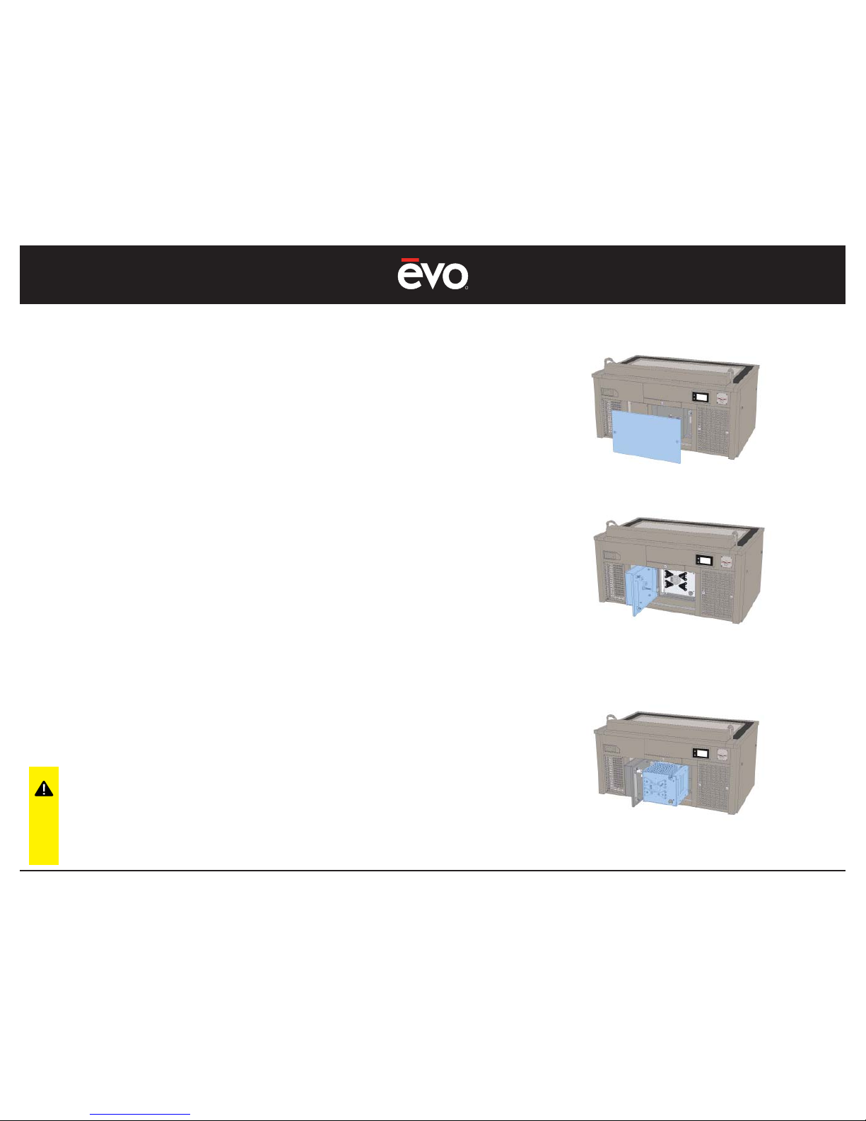
1. Using the 8mm hex key, unlock both latch locks and remove the
chef-side access panel.
2. Using the hex key, unlock both latch locks on the ESP door and
swing the door open to the left.
3. With the ESP door open, remove the ESP fi lter from its enclosure by
pulling outward on the ESP handle with one hand while lifting and
supporting the ESP fi lter with the other hand.
4. Clean the ESP fi lter by soaking in a degreaser solution and rinsing
clean. For faster cleaning, wash the fi lter in a commercial dish
washing machine.
5. Throughly dry the ESP fi lter before reinserting into the ESP fi lter
enclosure. Alternatively, have an extra standby ESP fi lter that is
clean and dry to facilitate fast cleaning.
IF THE ESP FILTER IS REINSTALLED AND A ARCING OR SNAPPING NOISE
IS HEARD, IMMEDIATELY TURN OFF THE VENTILATION SYSTEM AND
REMOVE THE FILTER TO ENSURE IT IS CLEAN AND DRY
CAUTION: Do not reinstall a wet
ESP fi lter. Doing so will cause
electric arcing and damage the
ESP Unicell voiding the EVent® 48E
warranty.
MAINTENANCE
Page 33
R
EVent 48E
33
MAINTENANCE
Cleaning - The Electrostatic Precipitator (ESP) Part 2
Turn Off Power Before Cleaning
The ESP ‘Unicell’ Filter requires special care and handling, and
cleaning. Be careful to never touch any internal components of the
ESP fi lter and particularly do not touch the ionizing wires.
The ESP fi lter is best cleaned in a commercial dishwasher, and dried
in warm air. It is important the ESP be washed and completely dry
before reinserting back into the ESP enclosure.
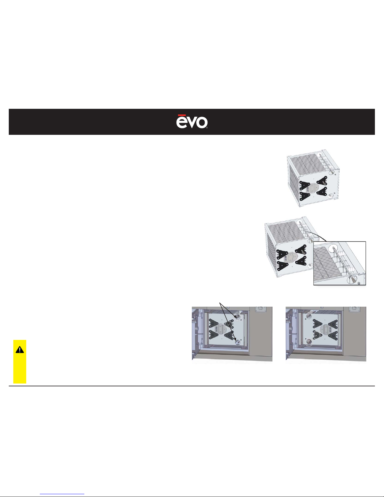
1. Always handle the ESP fi lter by the integral fi lter handle, and
carefully support the ESP fi lter when reinserting back into the ESP
enclosure (see Illustration 1).
2. Do not touch or disturb the ESP fi lter internal ionizing collector fi ns
or ionizing wires (see Illustration 2).
3. Reinsert the ESP by placing one hand on the ESP handle, and
supporting the underside of the ESP fi lter with the other hand.
CAUTION: Do not reinstall a wet
ESP fi lter. Doing so will cause
electric arcing and damage the
ESP Unicell voiding the EVent® 48E
warranty.
ESP inserted correctly
with springs facing right
ESP inserted incorrectly
with springs facing left
Illustration 1
Illustration 2
ESP Contact Springs
MAKE SURE THE ELECTRICAL CONTACT SPRINGS ARE FACING
TOWARD THE RIGHT SIDE OF THE ESP ENCLOSURE.
CLEAN ALL OIL AND GREASE DEBRIS FROM THE SPRINGS AND THE
ESP DOOR ELECTRICAL TERMINALS. FAILURE TO CLEAN
ELECTRICAL TERMINALS AND SPRINGS WILL CAUSE THE ESP
TO MALFUNCTION AND POSSIBLE DAMAGE TO THE EVENT UNIT.
Page 34
R
EVent 48E
34
MAINTENANCE
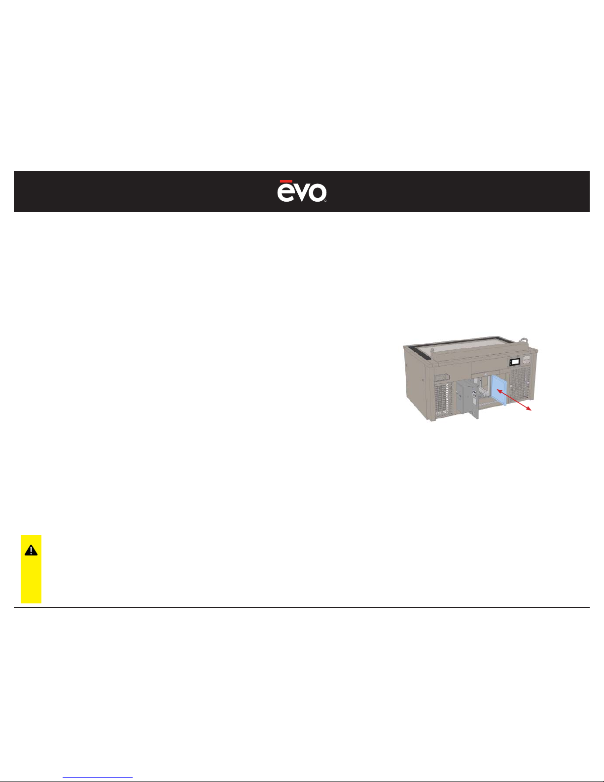
Cleaning - The Electrostatic Precipitator Aluminum Pre-Filter
Turn Off Power Before Cleaning
Located inside the ESP fi lter enclosure is an expanded aluminum Pre-Filter that
is designed to capture food debris that may have passed through the primary
grease fi lter. With normal cooking conditions, the Pre-Filter should be washed
weekly or replaced with a clean standby fi lter of the same type.
Depending on foods being cooked or the frequency of cooking, you may extend
cleaning cycles beyond one week to every other week.
1. Using the supplied 8mm hex key, unlock both latch locks and
remove the chef-side access panel.
2. Using the hex key, unlock both latch locks on the ESP door and
swing the door open to the left.
3. With the ESP door open, remove the expanded aluminum Pre-
Filter.
4. Clean the Pre-Filter by soaking in a degreaser solution and
rinsing clean. For fast cleaning, wash the fi lter in a commercial
dish washing machine. Wash as necessary to remove all grease
buildup.
5. Throughly dry the Pre-Filter before reinserting back into the ESP
enclosure. Alternatively, have an extra standby fi lter that is clean
and dry to facilitate faster cleaning.
Note: With the ESP door open, slide the
Aluminum Pre-Filter rearward and remove. To
reinstall, place the fi lter into the top and bottom
fi lter channel and slide forward.
CAUTION: Always install the
Aluminum Pre-Filter on the right
side of the ESP enclosure. Failure to
install the pre-fi lter on the right side
of the ESP may damage the unit
and void the EVent® 48E warranty.
Page 35
R
EVent 48E
35
MAINTENANCE
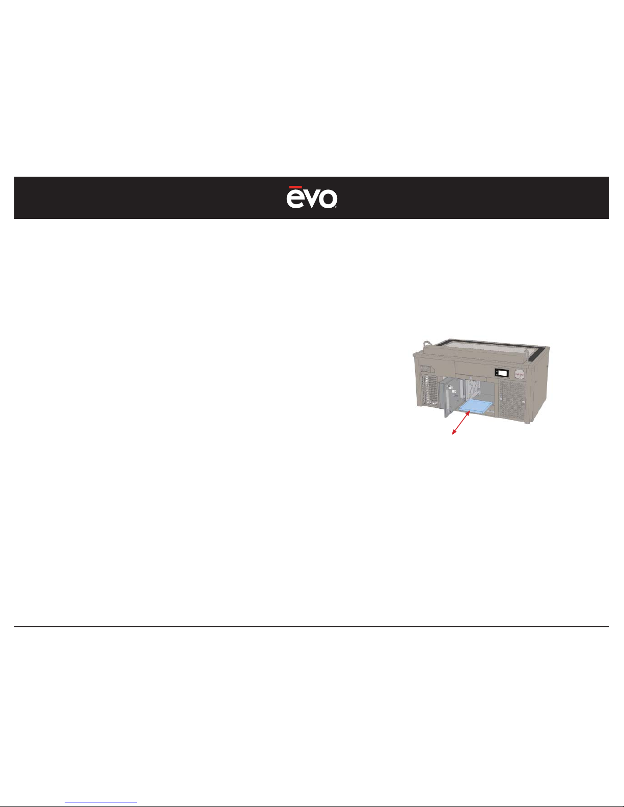
Cleaning - The Electrostatic Precipitator Bottom Pan
Turn Off Power Before Cleaning
Located inside the ESP enclosure under the ESP fi lter is a metal pan
designed to contain overfl ow grease not collected by the ESP fi lter.
With normal cooking conditions, the Bottom Pan should be washed
monthly or as needed.
1. Using the supplied 8mm hex key, unlock both latch locks on the
chef-side access panel and set aside the panel.
2. Using the 8mm hex key, unlock both latch locks on the ESP door
and swing the door open to the left.
3. Remove the ESP Filter.
4. Located under the ESP fi lter is the bottom pan. Remove the pan
and wash with soap and water and rinse dry clean. For faster
cleaning, wash the pan in a commercial dish washing machine.
Wash as necessary to remove all grease buildup.
5. Reinsert the Bottom pan the reverse of removal.
IF THE BOTTOM PAN HAS A COLLECTION OF GREASE, THIS IS AN
INDICATION THE ESP UNICELL FILTER IS OVERBURDENED BY GREASE
AND SMOKE AND REQUIRES MORE FREQUENT CLEANING
Note: With the ESP fi lter removed, lift and
remove the bottom pan and clean as
necessary.
Page 36
R
EVent 48E
36
MAINTENANCE
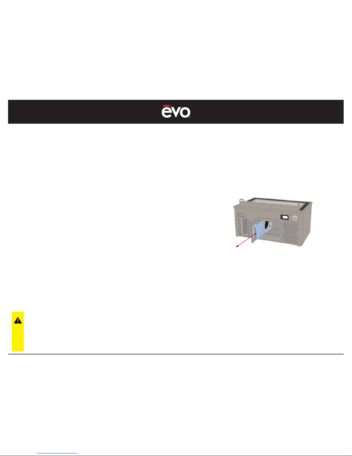
Replacing - The Disposable Charcoal Filter
Turn Off Power Before Cleaning
Located inside the ESP fi lter enclosure is a disposable charcoal fi lter
that is designed to retain a portion of the cooking odors passing
through the ventilation system. With normal cooking conditions, the
charcoal fi lter should be replaced with a fresh, clean fi lter monthly.
Depending on the food being cooked or the frequency of cooking,
the charcoal fi lter may be changed more frequently.
1. Using the 8mm hex key, unlock both latch locks and remove the
chef-side access panel.
2. Using the 8mm hex key, unlock both latch locks on the ESP door
and swing the door open to the left.
3. With the ESP door open, remove the ESP fi lter from its enclosure by
pulling outward on the ESP handle with one hand while lifting and
supporting the ESP fi lter with the other hand.
4. Remove the disposable charcoal fi lter located to the left of the
ESP by pulling outward.
5. Replace with a new clean charcoal fi lter. Reinsert the ESP
by placing one hand on the ESP handle, and supporting the
underside of the ESP fi lter with the other hand.
Note: With the ESP door open, slide the Charcoal
Filter rearward and remove. To reinstall, place
the fi lter into the top and bottom fi lter channels
and slide forward.
The Charcoal Filter has a white side and a black
colored side. Place the white side inward toward
the ESP fi lter.
CAUTION: Always install the
Charcoal Filter on the left side of
the ESP enclosure. Failure to install
the charcoal fi lter on the left side
of the ESP may damage the unit
and void the EVent® 48E warranty.
Page 37

R
EVent 48E
37
TROUBLESHOOTING
TROUBLESHOOTING ISSUES
This section describes how to solve common problems you may encounter when using your EVent® 48E Teppanyaki Table. Many
problems have simple solutions.
#1 On/Off Button Will Not Respond
1. Ensure the unit is plugged into a correct voltage and amperage receptacle. Have a certifi ed electrician check the cord wiring has not become dislodged
from inside the plug thereby preventing a secure electrical connection.
2. Check the electrical breaker panel to ensure the circuit breaker has not tripped. If it has been tripped, reset the breaker by switching to the “On” position.
3. Have a certifi ed electrician check the EVent Main Disconnect Switch inside the high-voltage panel is in the ON position (The red switch should be in the
horizontal position).
#2 The Fan Starts Then Stops After 5-10 Seconds
1. Ensure all duct cabinet doors are securely closed. Check the ESP door and ensure both latches are properly closed. Check the grease
box door is securely closed.
2. Check all fi lters are clean and the paper charcoal fi lter is new and clean.
3. Check the air tubes in the grease box for obstructions or grease build-up inside the tube preventing proper air sensing. If necessary,
clean air tubes with a pipe-cleaner (it may be necessary to remove the right side panel and remove the rubber tubing from the back
side of the grease box air tube to properly clean the tube. Once clean, reinstall the rubber tubing).
#3 The Fan Starts Then Stops When Cooking
1. Check all points in Issue #2 above. If issue persists, check the following:
2. Check the grease box bottom pan is making good contact with the presence switch positioned in the lower back portion of the
grease box.
3. Check the Charcoal Filter is making good contact with the presence switch positioned in the upper back portion of the charcoal
fi lter guide slot.
4. Check the Charcoal Filter is clean and new. An old paper charcoal fi lter may become deformed and not make good contact with
the presence switch.
#4 The Display Appears Functional But The Fan Does Not Start
1. If the display appears functional when the ON button is pressed but the fan does not start, and if the COOK button is pressed and it appears the heaters are
cycling on/off (see illustration page 14), then a Presence Switch is damaged and will require replacement.
2. A damaged Presence Switch is most likely to occur
3. If the ESP Green light on the outside of the ESP door is blinking, this is an indication the ESP Unicell is either soiled, is not making
proper electrical contact with the ESP door terminals, or the Unicell is damaged. DO NOT OPERATE THE EVENT UNIT IS THE ESP LIGHT IS
CONTINUOUSLY BLINKING. A service call must be reported to resolve this issue.
Page 38

R
EVent 48E
38
TROUBLESHOOTING
TROUBLESHOOTING ISSUES
#5 The Display Is Grey or The Display Does Not Respond
1. Ensure the display control panel is not broken or damaged. If the display is cracked or damaged, the previous settings at the time the display was damaged
will be frozen and no other selections can be made. A service call must be reported to replace the damaged display.
2. If the display is not damaged or cracked, then a grey or unresponsive display is an indication the ESP may be malfunctioning. If
the ESP is not clean or the electrical terminals on the ESP door are soiled and not making proper contact with the ESP Unicell, static
electricity may develop inside the ESP cabinet and damage the system controls.
3. If the ESP Green light on the outside of the ESP door is blinking, this is an indication the ESP Unicell is either soiled, is not making
proper electrical contact with the ESP door terminals, or the Unicell is damaged. DO NOT OPERATE THE EVENT UNIT IS THE ESP LIGHT IS
CONTINUOUSLY BLINKING. A service call must be reported to resolve this issue.
#6 The Upper Left Side Heater Is Over Heating
1. This is an indication the Heater Control Board is damaged and requires replacement. A service call must be reported to resolve this issue.
2. Cause of this issue is an indication the ESP may be malfunctioning. If the ESP is not clean or the electrical terminals on the ESP door
are soiled and not making proper contact with the ESP Unicell, static electricity may develop inside the ESP cabinet and damage
the Heater Control Board. If the ESP Green light on the outside of the ESP door is blinking, this is an indication the ESP Unicell is either
soiled, is not making proper electrical contact with the ESP door terminals, or the Unicell is damaged. DO NOT OPERATE THE EVENT
UNIT IS THE ESP LIGHT IS CONTINUOUSLY BLINKING. A service call must be reported to resolve this issue.
#7 The COOK Button Is On But The Heaters Are Not Heating
1. This is an indication the Heater Control Board may need to be reset. Momentarily turn power to the unit Off then ON from the main circuit breaker or by
unplugging the unit from the receptacle.
2. If there is a large temperature difference than what is desired, ensure the unit has enough time to reach its set point (From a cold startup, the unit will
take approximately 20 minutes to reach 450F). If large temperature difference continues, ensure the High Limit Switch has not been lowered from its
Factory Setting of 570F. ( The High Limit Switch is located inside the units high-voltage panel and must only be inspected or serviced by a licensed service
technician). If this issue persists, a service call must be reported.
#8 The Display Shows Red Fault Indicators
1. The EVent® 48E has a built-in diagnostics system on the control panel display. If the On/Off button is pressed and the ventilation fan
does not start, then a red FAULT light will highlight the troubled ventilation component. When you depress the FAULT light, the display
screen shows a helpful repair instruction to correct the issue. Listed on the following page is a list of ventilation systems faults and the
corrective action.
(See the following page for a description on Fault Indicators).
Page 39

R
EVent 48E
39
TROUBLESHOOTING
TROUBLESHOOTING ISSUES
CONTROL PANEL DISPLAY - FAULT INDICATORS
FAULT #1 - Aperture Inlet Duct
Remove aperture inlet air duct, inspect switch contact area, reinsert aperture.
Cycle power to restart.
FAULT #2 - Crumb Drawer
Remove crumb drawer, clean switch contact area and reinsert drawer.
Cycle power to restart.
FAULT #3 - Grease Filter
Open grease fi lter box. Remove grease fi lter, inspect switch contact area and reinsert fi lter and door.
Cycle power to restart.
FAULT #4 - Grease Drawer
Open grease fi lter box. Remove grease fi lter, slotted pan and grease drawer.
Inspect switch contact area and reinsert drawer, tray and fi lter door.
Cycle power to restart.
FAULT #5 - Pre-Filter
Open ESP door, check aluminum pre-fi lter switch contact area. Reinsert fi lter.
Cycle power to restart.
FAULT #6 - Charcoal Filter
Open ESP door, check charcoal fi lter switch contact area. Reinsert or replace fi lter.
Cycle power to restart.
Page 40
R
EVent 48E
40
APPENDIX 1
REQUIRED EVENT SYSTEM MAINTENANCE SCHEDULE
USE AND MAINTENANCE SHALL BE IN ACCORDANCE WITH THE STANDARD FOR VENTILATION CONTROL AND FIRE PROTECTION OF
COMMERCIAL COOKING OPERATIONS, N.F.P.A. 96 (current edition)
1-MONTH OWNERS VENTILATION DUCT AND FILTER MAINTENANCE
Remove all metal fi lters and wipe wash all internal duct areas including ESP enclosure and clean ESP door electrical terminals.
Thoroughly clean entire internal duct system, and clean air sensing tubes in grease box.
Ensure there is no oil or grease remaining in between duct channels and around presence switches.
Wash Stainless Steel Grease Filter.
Wash Grease Box Grease Filter Bracket, Bottom Support and Bottom Pan.
Wash Aluminum Pre-Filter.
Wash ESP Unicell.
Replace Charcoal Filter.
1-MONTH OWNERS FIRE SYSTEM INSPECTION AND MAINTENANCE
Monthly inspections shall be performed as per NFPA-17A and are required by Buckeye Fire Equipment.
On a monthly basis the owner of the Kitchen Mister Fire Suppression System must perform a “quick check” to verify the following:
1. The extinguishing system is in it's proper location
2. The manual actuators are unobstructed.
3. The tamper indicators and seals are intact.
4. The maintenance tag or certifi cate is up to date and in place.
5. No obvious physical damage or condition exists that may prevent operation.
6. The pressure gauge is in the operable range.
7. The nozzle blow off caps are intact and undamaged.
8. The inlet aperture and ventilation duct have not been replaced, modifi ed, or relocated.
If any defi ciencies that are found, the owner is to contact an Authorized Buckeye Fire Equipment Distributor immediately.
Note: A record of monthly inspections must be kept by the owner of the system that includes the
date of inspection, the person performing the inspection, and any corrective action required.
Page 41
R
EVent 48E
41
APPENDIX 1
REQUIRED EVENT SYSTEM MAINTENANCE SCHEDULE
6-MONTH MAINTENANCE
Inspection and testing of the fi re suppression system as per the Buckeye Model BFR-5
Kitchen Mister Automatic Fire Suppression System manual Chapter 5, Revision 5 “System Inspection and Maintenance”.
ANNUAL 12-MONTH MAINTENANCE
Inspection and testing of the fi re suppression system as per the Buckeye Model BFR-5
Kitchen Mister Automatic Fire Suppression System manual Chapter 5, Revision 5 “System Inspection and Maintenance”.
12-YEAR MAINTENANCE
Inspection and testing of the fi re suppression system as per the Buckeye Model BFR-5
Kitchen Mister Automatic Fire Suppression System manual Chapter 5, Revision 5 “System Inspection and Maintenance”.
Page 42
R
EVent 48E
42
APPENDIX 2
FILTER AND SURFACE CLEANING MAINTENANCE SCHEDULE
Clean Each Day Wash End Of Day
Wash Each 2 Weeks
Or As Necessary
Every 2-3 Weeks
Or As Necessary
Cooking Surface Ventilation Inlet Aperture Stainless Steel Grease Filter Replace Paper Charcoal Filter
Granite Surfaces Ventilation Inlet Duct Grease Filter Enclosure Remove Oil Film From Ducts & ESP
Stainless Steel Top Surfaces Crumb Drawer ESP Filter Unicells
Stainless Steel Side Panels ESP Bottom Pan
Stainless Steel Toe Kicks ESP Aluminum Pre-Filter
Wipe Clean All Internal Ducts
Establish a regular fi lter and surface cleaning schedule to ensure the safety and proper operation of your Evo EVent® unit.
Depending on the types of foods being cooked and the duration of cooking, you may need to adjust your cleaning schedule.
Filter Item Number Type
Stainless Steel Grease Filter 13-0220-EVT Washable
ESP Aluminum Pre-Filter 13-0110-EVT Washable
ESP Filter Unicell 13-0200-EVT Washable
Evo Branded Paper Charcoal Filter 13-0230-EVT Disposable
Do not use stainless steel cleaners or degreasers on the electronic display panel. Clean with damp terry cloth towel using warm water only.
ONLY USE EVO BRANDED PAPER CHARCOAL FILTER PRODUCTS TESTED AND CERTIFIED FOR USE WITH THIS EQUIPMENT. THE USE OF OTHER CHARCOAL FILTER
PRODUCTS WILL ADVERSELY AFFECT AIR QUALITY AND VOID THE MANUFACTURER’S WARRANTY.
Phone: 800-438-8898
Monday - Friday from 8am to 7pm EST
Page 43
R
EVent 48E
43
APPENDIX 3
CLEANING THE COOKING SURFACE
It’s important to keep you cooking surface clean to prevent food from sticking, to provide better heat conductivity, to prevent unwanted fl avors,
and to provide a better overall appearance of your display cooking unit.
PROCEDURE
1. Start by scraping large particles of debris with the side of a metal spatula. Scrape the debris into the spillover tray located at the
lower left of the cooking surface.
2. Place one gray polishing pad between the handle base and one grill screen, so the grill screen makes direct contact with the
cooking surface.
3. Pour a small amount of vegetable oil on the cook surface and lightly scrub the surface in a circular motion.
4. Wipe the surface clean with a paper towel or cotton terrycloth towel.
5 Finish by wiping a small amount of vegetable oil over the entire surface to condition the steel surface and help prevent rusting.
TOOLS NEEDED TO PROPERLY CLEANING THE COOKING SURFACE
Metal Scraper
Grill Screen Handle Grill Screen
Grill Polishing Pad
Vegetable Oil
Paper Towels or Terrycloth Towels
TIPS FOR SUCCESS
1) The cooktop is easier to clean when slightly warm.
2) Clean the cooktop after each use.
3) A scraper also works well for removing heavy food particles.
4) Small amount of water can be used to loosen food particles when the cooktop is slightly warmed. Never put water on a hot
cooking surface, and never create steam that may enter the inlet aperture and damage the fusible fi re system link.
Page 44

R
EVent 48E
44
APPENDIX 4
FIRE SUPPRESSION SYSTEM
The Evo EVent® 48E is equipped with the latest in technology and safety and includes a Buckeye Model BFR-5, Kitchen Mister
Automatic Fire Suppression System. The Model BFR-5 Fire Suppression System must be periodically inspected and maintained by an
Authorized Factory Trained Buckeye distributor. Inspection and maintenance procedures must adhere to the design, installation, and
maintenance manual part# BFR-TM, NFPA 17A, Sections of NFPA 96 where applicable, Local, State, and National Codes as well as the
UL listing. See fi re system maintenance schedule listed in Appendix 1.
IN CASE OF FIRE
1. Evacuate all personnel and customers from the fi re area.
2. Call the fi re department.
3. If your EVent fi re control system has not automatically activated, you may activate it manually by pulling the handle on the manual pull station.
When the fi re has been extinguished, and the fi re department has deemed it safe to re-enter and has determined the cause of the fi re, call Evo at 503-
626-1802 to dispatch a fire contractor to reset and recharge the system. Once the equipment has cooled and it is safe to touch, clean the discharge area
using sponges with hot soapy water and detergents.
CAUTION: DO NOT USE ANY FLAMMABLE CLEANING SOLVENTS.
NOTE: It is critical to determine the cause of the fi re and to correct the conditions which caused the fi re prior to re-starting your operation. Under no
circumstances should cooking operations be attempted before a factory trained and authorized Buckeye Fire Equipment distributor re-instate the integrity of
your fi re suppression system.
MAINTENANCE
To ensure the best possible fi re protection for the restaurant:
1. Arrange for proper inspection and maintenance of the fi re control system as well as hand portables.
2. Eliminate all potentially combustible materials and arrange for their proper storage.
3. Arrange for upgrading of the fi re suppression system if cooking equipment is added or revised and provide protection for
changes made to the ventilation system.
4. Arrange for a continuing education program in the restaurant fi re suppression system operation as new employees are added to
the staff.
5. Assure that good housekeeping practices have been maintained to eliminate potential fi re hazards.
REGULARLY SCHEDULED INSPECTION
The Buckeye Fire Equipment Kitchen Mister Restaurant Cooking Area Fire Suppression System is a sophisticated fi re suppression system,
involving intricate mechanical components. To ensure the proper operation of the system, regular inspection and maintenance must
be performed by an authorized trained Buckeye Fire Equipment distributor on a semi-annual basis, and after every periodic hood and
duct cleaning (whichever occurs more frequently). This system is made up of individual components that are listed by Underwriters
Laboratories Inc, with limitations contained in the detailed installation manual. The authorized distributor must be consulted after the
Page 45

R
EVent 48E
45
APPENDIX 4
FIRE SUPPRESSION SYSTEM
system is discharged or whenever changes are planned for the system and/or area of protection.
NFPA 17A and Buckeye Fire Equipment require that regularly scheduled (at a minimum of once a month) inspections of the system be
conducted by the owner (or his representative). These monthly inspections are necessary to assure that the system is in proper working
order and is ready when required.
The following “quick review” of the Kitchen Mister System must include, but not limited to the following:
1. Determine that the cylinder, control head, gas valve, and all other components of the system are in place and has not been
tampered with.
2. Determine that all appliances are still in their original position, as when the system was installed.
3. Check that the manual pull station is unobstructed and in clear view with all labeling and instructions visible.
4. Visually inspect the pressure gauge on the cylinder valve assembly to make sure the system pressure is within proper range. The
yellow pointer should be in the middle of the green operable range.
5. Visually inspect the system detection lines to make sure that the cable and fusible links are not damaged, obstructed or have
been moved.
6. Inspect all nozzles, making sure they are clean and free from any grease or carbon build-up. Assure that all blow-off covers are in
place.
7. Check that all inspection tags or certifi cates are in place and up to date. A record of monthly inspections shall be maintained
showing the date of the inspection, who conducted the inspection and what actions were taken if required.
8. If any defi ciencies are found, call your authorized trained Buckeye Fire Equipment distributor so that the appropriate corrective
action can be taken.
NOTE: The best method of fi re prevention is good “housekeeping practices” which eliminate potential fi re hazards. Inspect the overall
cleanness and operation of the appliance, plenum and fi lters. If any problems or defi ciencies are found, appropriate corrective action
must be taken immediately, by notifying the appropriate parties.
Call Evo, Inc. at 503-626-1802 to confi rm or schedule your semi-annual inspection and maintenance visit. At this time, it is also good
practice to visually inspect all hand portable fi re extinguishers to verify that each is in good working condition. Refer to extinguisher’s
manual for detailed instructions.
Page 46

R
EVent 48E
46
APPENDIX 5
RESTARTING AFTER A FIRE SYSTEM DISCHARGE
The fi re suppression system in the EVent unit uses a Potassium Carbonate (Potash) liquid solution that is dispensed under pressure from 2 nozzles on each
right and left side of the Inlet Aperture and 1 nozzle located inside the grease fi lter box. A Fire System Discharge can occur because there is a fi re within the
cooking surface area with the ventilation fan operating, or there is a fi re system discharge the ventilation fan Off and not operating.
THE FOLLOWING EXPLAINS CAUSES ASSOCIATED WITH A FIRE SYSTEM DISCHARGE:
WHEN THE VENTILATION FAN IS OPERATING
1) There is a fi re within the cooking surface area causing fl ame to enter the inlet aperture and release the fusible link.
2) There is excessive steam generated on the cooking surface which enters the inlet aperture and releases the fusible link.
3) The Fire Pull Station has been triggered discharging the fi re system.
WHEN THE VENTILATION FAN IS OFF
1) The inlet aperture is being cleaned using hot water or steam causing a release of the fusible link.
2) The inlet aperture is being cleaned using corrosive cleaners (oven cleaner) which has damaged the fusible link causing a release of the fusible link.
3) The inlet aperture fusible link is disturbed during cleaning causing a release of the fusible link.
4) The Fire Pull Station has been triggered discharging the fi re system.
RESTARTING AFTER A FIRE SYSTEM DISCHARGE:
1) IF THERE IS A FIRE EMERGENCY, IMMEDIATELY CALL THE LOCAL FIRE DEPARTMENT TO REPORT THE ISSUE.
2) Call the Fire Contractor associated with servicing your EVent unit to report the incident and request a service call. The Fire Contractor telep
h
is found on the service tag affi xed to the fi re pull station.
3) Report the issue to Evo, Inc. by calling Evo Support at 503-626-1802 or Toll-Free at 866-626-1802.
CLEANING THE EVENT UNIT AFTER A FIRE SYSTEM DISCHARGE:
IF THE VENTILATION FAN WAS OPERATING
1) Request an Authorized Buckeye Fire Contractor service the EVent unit to recharge the fi re suppression system
2) Inspect the internal duct system for fi re damage or melting of internal duct components. If fi re melt damage is found call Evo, Inc at 503-626-1802. If no
internal duct damage is found, remove and wash the inlet aperture, remove all fi lters and support brackets and wash all parts throughly to remove all traces
of fi re suppression chemical. Using soap and water, throughly wash and wipe all traces of fi re suppression chemical from the inside of the duct and ESP
enclosure and ESP door components.
3) Replace the charcoal fi lter with a new charcoal fi lter.
IF THE VENTILATION FAN WAS NOT OPERATING
1) Request an Authorized Buckeye Fire Contractor service the EVent unit to recharge the fi re suppression system
2) Remove and wash the inlet aperture, remove all fi lters and support brackets and wash all parts throughly to remove all traces of fi re suppression
chemical. Using soap and water, throughly wash and wipe all traces of fi re suppression chemical from the inside of the duct and ESP enclosure and ESP door
components.
3) Replace the charcoal fi lter with a new charcoal fi lter.
Page 47
R
EVent 48E
47
FIRE SYSTEM ALARM MICRO SWITCH
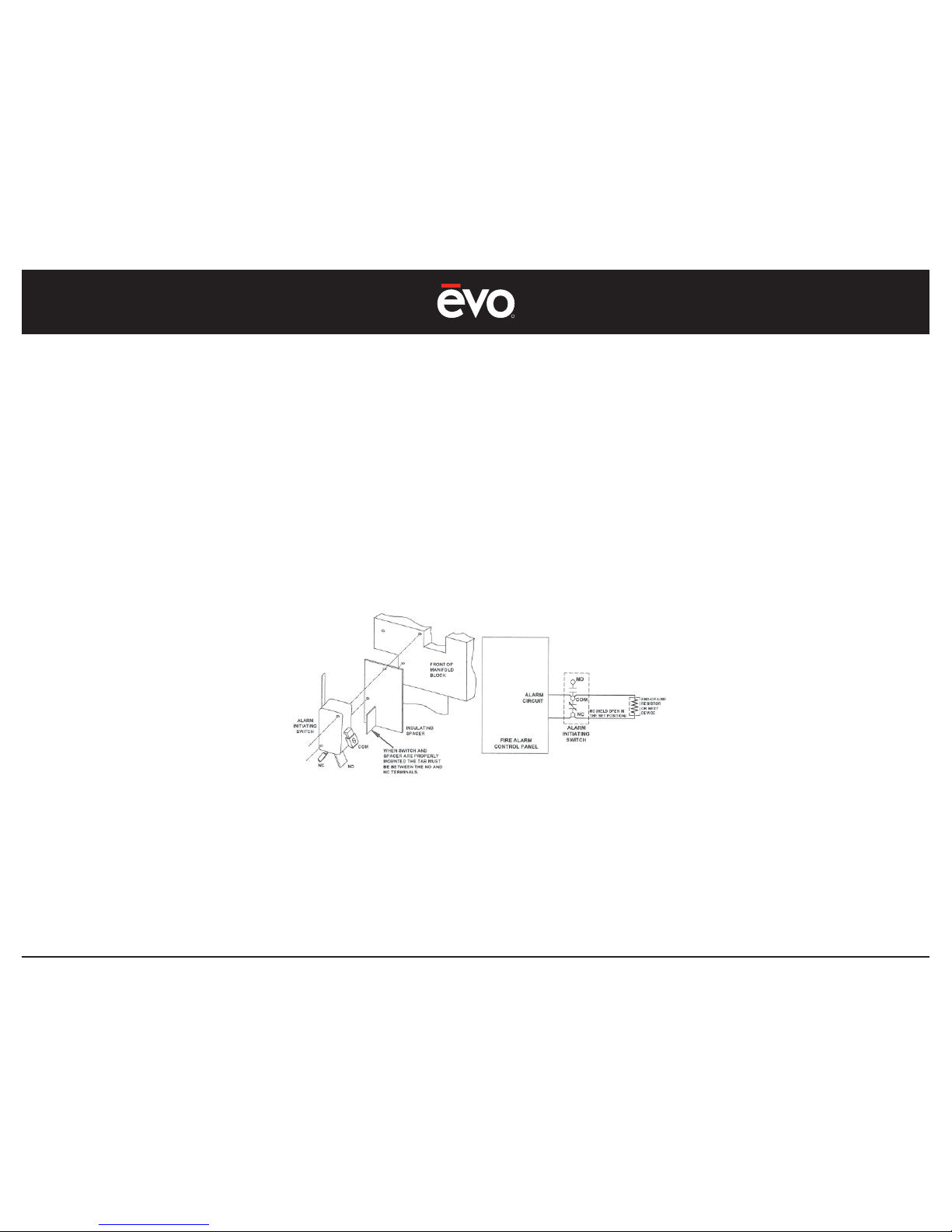
An Alarm Micro Switch is available inside the Buckeye Switch Release Mechanism (SRM) control box that allows the connection for an alarm initiating circuit
as per NFPA 72 “Nation Fire Alarm Code”. This switch is pre-installed at the Evo factory by an Authorized Buckeye Distributor and is location on the front of the
Manifold Block.
The following diagram is supplied for reference purposes only. Refer to installation instructions supplied with the Buckeye Kitchen Mister Technical Manual
BFR-TM, Edition January 1, 2013, Appendix B - Accessories, Page B-1, Revision 5.
APPENDIX 6
Page 48
R
EVent 48E
48
Specifi cations 4 Heating Elements (up to 2 heaters energized at any given time)
Cooking Surface Dimensions (overall griddle size) 48” x 24” (1219mm x 610mm)
Cooking Zone Dimensions (direct heat area)
23.25” x 16.25” (591mm x 413mm)
Heating Element Power (KW/BTU)
6KW / 20,473 BTU (2 heaters)
Heating Element Voltage (V)
208V - 220V
Phase
1
Frequency (Hz)
60 HZ
Current (A)
32 A (2 heaters maximum plus ventilation fan in full operation)
Maximum Current Requirement (A)
40 A (minimum provisioned circuit)
Plug Wire
2 Pole, 1 Wire Ground
Plug
NEMA 6-50P, 2 Pole, 3 Wire, Straight Blade
APPENDIX 7
Page 49

Evo, Inc.
20560 SW 115th Ave., Tualatin, OR 97062 USA
Ph 866.626.1802 Fax 503.213.5869 [email protected]
Evo is protected under U.S. Patent 8,530,795 and U.S. Patents Pending. Evo is a registered trademark of Evo, Incorporated. ©2017 All rights reserved.
the natural way to cook
the natural way to cook
®
®
 Loading...