

Page 1
WARNING
Read this Guide thoroughly. It contains important safety information.
Minimum recommended operators age: 16 years old.
Keep this Operators Guide in the boat.
Operator’s Guide
200, 225, 250, 300 HORSEPOWER
*216348*
Revision D
Page 2

Page 3

Operator’s Guide
200 / 225 / 250 / 300 HORSEPOWER
*216348*
Revision – D
CALIFORNIA PROPOSITION 65 WARNING
WARNING
This product contains or emits chemicals known to the state of California to cause
cancer and birth defects or other reproductive harm.
Page 4

Page 5

Easy to Own and Operate
• 5-Year* Engine Warranty
• 5-Year Non-Declining Corrosion Warranty
• 5-Years or 500 hours No Scheduled Dealer
Maintenance (Normal Recreational Use)
• No Operational Break-In Procedure
• Easy Starts (no choking or priming)
• Digital Engine Management
• Self Flushing Cooling System
• Long Term Storage Design
• Simplified Winterization Procedure
• Digital Diagnostics
• Low Oil Usage
Durable and Reliable
• Full Corrosion Protection
• Evinrude E-TEC G2 Lubrication System
• Robust, Heavy-Duty Design
• Extra Capacity Water Pump
• Iridium Spark Plugs
• Vibration Isolated Electronics
• Beltless 50 Amp Charging System
• Stainless Steel Thermostat
• Nickel/Chrome-Faced Piston Rings
• Micro Finished Connecting Rods/Crankshaft
Cleaner and Quieter
• EPA Emissions Compliance
• European Union Emissions Compliance
• California 3-Star Emissions Compliance
• Sealed Fuel System
• Low Friction Design (No powerhead gears, belts,
cams, oil scraping rings, or mechanical oil pump)
• Full Length Insulated Engine Covers
• Quiet Signature Sound
• Air Intake/Silencer
• Idle Air Bypass
Features at a Glance
The following trademarks are the property of Bombardier Recreational Products Inc. or its affiliates:
Evinrude® RPM Tune™ I-Command™
Evinrude® E-TEC® G2 BRP Logo S.A.F.E.™
Evinrude® Genuine Parts 2+4™ Fuel Conditioner SystemCheck™
Evinrude® XD100™ HPF Pro™ Gearcase Lubricant Triple-Guard™ Grease
Evinrude® XD50™ PowerSync™ Evinrude ICON II Remote Control
Evinrude ICON Touch™
© 2015 BRP US Inc. All rights reserved.
*3-Years + 2-Year BRP Extended Service Terms (B.E.S.T.)
Refer to Warranty Statement and B.E.S.T. contract
Page 6

Table of Contents
About This Guide . . . . . . . . . . . . . . . . . . . . . . . . . . . . . . . . . 4
Important Safety Messages . . . . . . . . . . . . . . . . . . . . . . . . . 5
Product References, Illustrations and Specifications . . . . . . . . . . . . . . . . . 7
Declaration of Conformity . . . . . . . . . . . . . . . . . . . . . . . . . . . . . . . . . . . . . . . . 8
Using Your Evinrude E-TEC G2 Outboard
Important On-Product Labels . . . . . . . . . . . . . . . . . . . . . . 10
Component Identification
200, 225, 250, 300 HP 74° V6 . . . . . . . . . . . . . . . . . . . . . . . 12
2–Stroke Engine Oil and Fuel . . . . . . . . . . . . . . . . . . . . . . 14
2–Stroke Engine Oil Requirements . . . . . . . . . . . . . . . . . . . . . . . . . . . . . . . 14
Oiling System information . . . . . . . . . . . . . . . . . . . . . . . . . . . . . . . . . . . . . . 14
Fuel Requirements . . . . . . . . . . . . . . . . . . . . . . . . . . . . . . . . . . . . . . . . . . . . . 16
Fuel System Information . . . . . . . . . . . . . . . . . . . . . . . . . . . . . . . . . . . . . . . . 16
Operation . . . . . . . . . . . . . . . . . . . . . . . . . . . . . . . . . . . . . . . 19
Safety Information . . . . . . . . . . . . . . . . . . . . . . . . . . . . . . . . . . . . . . . . . . . . . 19
Engine Starting / Stopping . . . . . . . . . . . . . . . . . . . . . . . . . . . . . . . . . . . . . . 19
Remote Controls — Evinrude ICON II Control System . . . . . . . . . . . . . . . 23
Remote Controls - Evinrude Mechanical Controls . . . . . . . . . . . . . . . . . . . 24
Fuel Economy . . . . . . . . . . . . . . . . . . . . . . . . . . . . . . . . . . . . . . . . . . . . . . . . 25
Trim, Tilt and Steering . . . . . . . . . . . . . . . . . . . . . . . . . . . . 26
Power Trim and Tilt . . . . . . . . . . . . . . . . . . . . . . . . . . . . . . . . . . . . . . . . . . . . 26
Impact Damage Protection . . . . . . . . . . . . . . . . . . . . . . . . . . . . . . . . . . . . . . 28
Dynamic Power Steering (DPS) . . . . . . . . . . . . . . . . . . . . . . . . . . . . . . . . . . 29
Engine Monitoring . . . . . . . . . . . . . . . . . . . . . . . . . . . . . . . 30
Displays and Gauges . . . . . . . . . . . . . . . . . . . . . . . . . . . . . . . . . . . . . . . . . . . 30
Speed Adjusting Failsafe Electronics (S.A.F.E.) . . . . . . . . . . . . . . . . . . . . . 30
Special Operating Conditions . . . . . . . . . . . . . . . . . . . . . . 32
Cold and Freezing Weather . . . . . . . . . . . . . . . . . . . . . . . . . . . . . . . . . . . . . . 32
Multiple Outboard Operation . . . . . . . . . . . . . . . . . . . . . . . . . . . . . . . . . . . . 32
High Altitude . . . . . . . . . . . . . . . . . . . . . . . . . . . . . . . . . . . . . . . . . . . . . . . . . . 32
Salt Water . . . . . . . . . . . . . . . . . . . . . . . . . . . . . . . . . . . . . . . . . . . . . . . . . . . . 32
Shallow Water . . . . . . . . . . . . . . . . . . . . . . . . . . . . . . . . . . . . . . . . . . . . . . . . 32
Under Tow . . . . . . . . . . . . . . . . . . . . . . . . . . . . . . . . . . . . . . . . . . . . . . . . . . . 32
Weedy Water . . . . . . . . . . . . . . . . . . . . . . . . . . . . . . . . . . . . . . . . . . . . . . . . . 32
Transporting the Outboard . . . . . . . . . . . . . . . . . . . . . . . . 33
Trailering . . . . . . . . . . . . . . . . . . . . . . . . . . . . . . . . . . . . . . . . . . . . . . . . . . . . . 33
Transporting / Storage . . . . . . . . . . . . . . . . . . . . . . . . . . . . . . . . . . . . . . . . . 34
Pre-Ride Inspection . . . . . . . . . . . . . . . . . . . . . . . . . . . . . . 35
Page 7

Maintenance
Engine Emissions Installation Information . . . . . . . . . . . .38
Maintenance & Inspection Schedule . . . . . . . . . . . . . . . . .40
Engine Care Products . . . . . . . . . . . . . . . . . . . . . . . . . . . . . . . . . . . . . . . . . . 40
Service . . . . . . . . . . . . . . . . . . . . . . . . . . . . . . . . . . . . . . . . .41
Anodes . . . . . . . . . . . . . . . . . . . . . . . . . . . . . . . . . . . . . . . . . . . . . . . . . . . . . . . 41
Flushing . . . . . . . . . . . . . . . . . . . . . . . . . . . . . . . . . . . . . . . . . . . . . . . . . . . . . . 41
Fuses . . . . . . . . . . . . . . . . . . . . . . . . . . . . . . . . . . . . . . . . . . . . . . . . . . . . . . . . 42
Gearcase Lubricant Level . . . . . . . . . . . . . . . . . . . . . . . . . . . . . . . . . . . . . . . 42
Hull Finish . . . . . . . . . . . . . . . . . . . . . . . . . . . . . . . . . . . . . . . . . . . . . . . . . . . . 43
Outboard External Finish . . . . . . . . . . . . . . . . . . . . . . . . . . . . . . . . . . . . . . . . 43
Scratch Repair . . . . . . . . . . . . . . . . . . . . . . . . . . . . . . . . . . . . . . . . . . . . . . . . . 43
Spark Plugs . . . . . . . . . . . . . . . . . . . . . . . . . . . . . . . . . . . . . . . . . . . . . . . . . . . 43
Submerged Outboard . . . . . . . . . . . . . . . . . . . . . . . . . . . . . . . . . . . . . . . . . . . 43
Storage . . . . . . . . . . . . . . . . . . . . . . . . . . . . . . . . . . . . . . . . .44
Short-Term Storage . . . . . . . . . . . . . . . . . . . . . . . . . . . . . . . . . . . . . . . . . . . . 44
Long-Term Storage (Winterization) . . . . . . . . . . . . . . . . . . . . . . . . . . . . . . . . 44
Troubleshooting . . . . . . . . . . . . . . . . . . . . . . . . . . . . . . . . .46
S.A.F.E. Reset . . . . . . . . . . . . . . . . . . . . . . . . . . . . . . . . . . . . . . . . . . . . . . . . . 47
Emergency Start Procedure . . . . . . . . . . . . . . . . . . . . . . . . . . . . . . . . . . . . . . 48
Product Information
Installation . . . . . . . . . . . . . . . . . . . . . . . . . . . . . . . . . . . . . .50
Transom Height . . . . . . . . . . . . . . . . . . . . . . . . . . . . . . . . . . . . . . . . . . . . . . . . 50
Outboard Shipping Cover . . . . . . . . . . . . . . . . . . . . . . . . . . . . . . . . . . . . . . . 50
Installing the Outboard . . . . . . . . . . . . . . . . . . . . . . . . . . . . . . . . . . . . . . . . . . 51
Boat-Mounted Fuel Filters . . . . . . . . . . . . . . . . . . . . . . . . . . . . . . . . . . . . . . . 51
Battery . . . . . . . . . . . . . . . . . . . . . . . . . . . . . . . . . . . . . . . . . . . . . . . . . . . . . . . 52
Accessory Battery Connection . . . . . . . . . . . . . . . . . . . . . . . . . . . . . . . . . . . 53
Water Pressure . . . . . . . . . . . . . . . . . . . . . . . . . . . . . . . . . . . . . . . . . . . . . . . . 53
Propeller . . . . . . . . . . . . . . . . . . . . . . . . . . . . . . . . . . . . . . . . . . . . . . . . . . . . . 54
Adjustments . . . . . . . . . . . . . . . . . . . . . . . . . . . . . . . . . . . . . . . . . . . . . . . . . . 55
Specifications . . . . . . . . . . . . . . . . . . . . . . . . . . . . . . . . . . .56
200, 225, 250, 300 HP (3.4 Liter, 74° V6) Models . . . . . . . . . . . . . . . . . . . . . . 56
Product Warranty Information . . . . . . . . . . . . . . . . . . . . . .59
Readiness Test . . . . . . . . . . . . . . . . . . . . . . . . . . . . . . . . . .71
Frequently Asked Questions . . . . . . . . . . . . . . . . . . . . . . .73
Change of Address / Change of Ownership . . . . . . . . . . .75
Confirmation of Receipt . . . . . . . . . . . . . . . . . . . . . . . . . . .77
Page 8
4
About This Guide
This Operator’s Guide is an essential part of
your Evinrude E-TEC G2 outboard. It contains pertinent information which, if followed,
will provide you with a thorough understanding needed for proper operation, maintenance, care, and—above all—safety. Safety
is our first priority and it should be yours too.
It is strongly recommended you read this
Guide from cover to cover. The more you
know and understand about your Evinrude
E-TEC G2 outboard, the greater the safety
and pleasure you will get from using it. Following this recommendation will assure the completeness of the information essential to your
safety, the safety of any passengers, and other water users.
This Operator’s Guide identifies important
safety messages.
Although the mere reading of such information does not eliminate the hazard, the understanding and application of the information
will promote the correct use of your outboard
engine.
This Guide should be kept in a waterproof bag
with the outboard at all times during operation. If the product ownership is transferred,
this Guide should be forwarded to the new
owners.
A responsible, educated boater will fully appreciate the pleasures of boating and will be a
safe boater. Boating Safety Classes are conducted by the U.S. Coast Guard Auxiliary, the
U.S. Power Squadron and some Red Cross
Chapters. For information about classes, call
toll free 1-800-336-BOAT.
For additional information about boating safety and regulations, call:
• U.S. Coast Guard Boating Safety Hotline
1-800-368-5647.
Outside North America please contact your
Dealer or distributor for details about boating
safety.
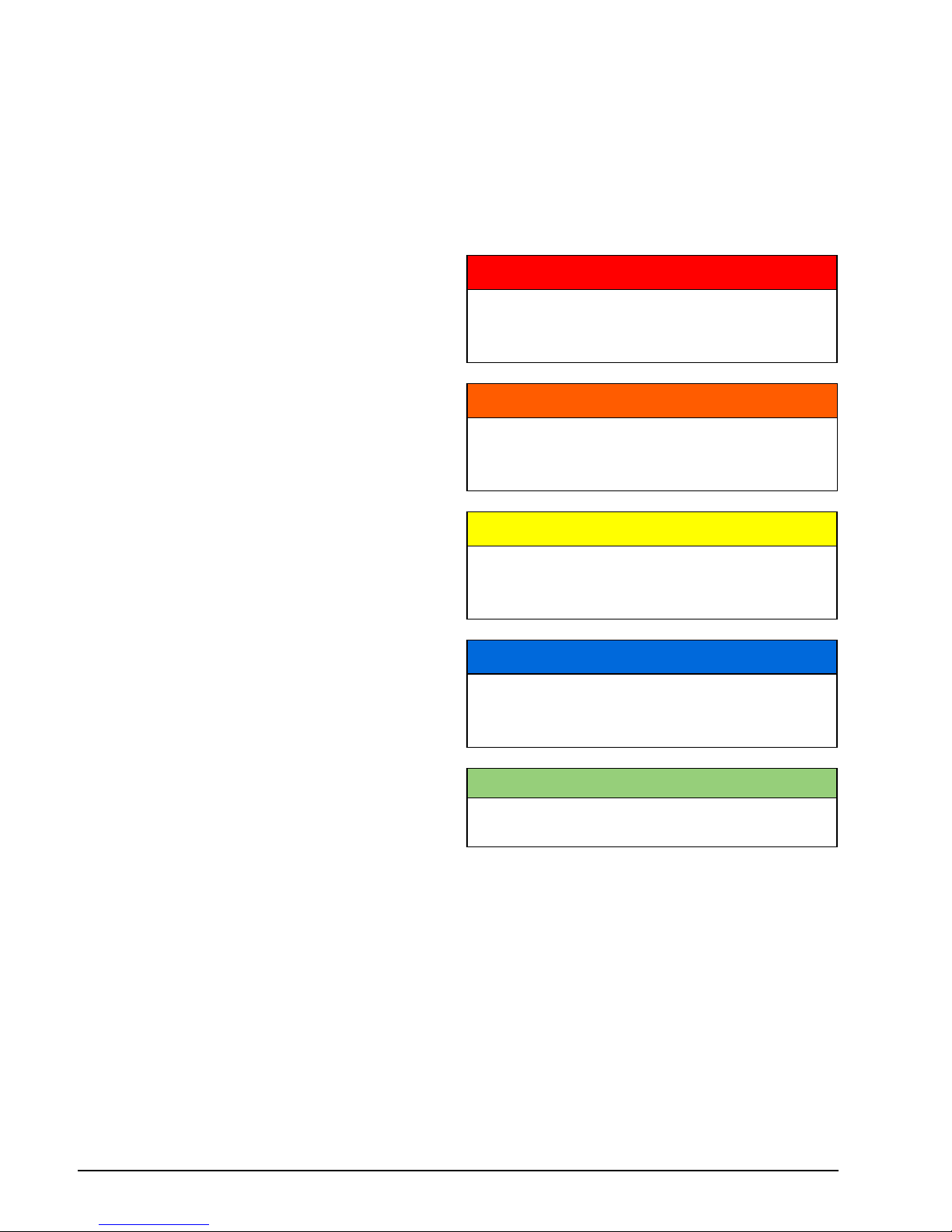
This Operator’s Guide uses the following signal words identifying important safety messages.
IMPORTANT: Identifies information that will
help with assembly and operation of the product.
Safety Alert Symbol
This is the Safety Alert symbol. It is used
to alert you to potential personal injury
hazards. Obey all safety messages that
follow this symbol to avoid possible injury
or death.
DANGER
Indicates a hazardous situation which, if
not avoided, will result in death or serious injury.
WARNING
Indicates a hazardous situation which, if
not avoided, could result in death or serious injury.
CAUTION
Indicates a hazardous situation which, if
not avoided, could result in minor or
moderate injury
NOTICE
Indicates an instruction which, if not followed, could severely damage engine
components or other property.
ENVIRONMENTAL NOTE
A note which provides tips and behaviors related to protecting the environment.
Page 9

5
Important Safety Messages
This Operator’s Guide contains essential information to help prevent personal injury and
damage to equipment. Safety messages appear throughout this Guide in the applicable
section.
Be careful! Human error is caused by many
factors: carelessness, fatigue, overload, preoccupation, unfamiliarity of operator with the
product, drugs and alcohol to name a few.
Damage to your boat and outboard can be
fixed in a short period of time, but injury or
death, has a lasting effect.
SAFETY MEASURES — General
WARNING
For your safety and the safety of others,
follow all safety warnings and recommendations. Do not disregard any of the
safety precautions and instructions.
Anyone operating your boat should first
read and understand this guide before
they operate your boat and outboard.
–
To fully appreciate the pleasures, enjoyment and excitement of boating there are
some basic rules that should be observed and followed by any boater.
Some rules may be new to you and others may be common sense or obvious...
irrespective, take them seriously!
–
Be sure at least one of your passengers
knows how to handle your boat in case of
an emergency.
–
All passengers should know the location
of emergency equipment and how to use
it.
–
Know the marine traffic laws and obey
them.
–
All safety equipment and personal floatation devices must be in good condition
and suitable for your type of boat. Always
comply with the regulations that apply to
your boat.
–
Remember, gasoline fumes are flammable and explosive. Always adhere to the
fueling procedure contained in this Operator’s Guide and those given to you by
the fueling station. Always verify fuel level before use and during the ride. Apply
the principle of 1/3 fuel to destination, 1/
3 back and 1/3 reserve fuel supply. Do
not carry spare fuel or flammable liquids
in any storage or engine compartments.
–
Whenever running the engine, assure
there is proper ventilation to avoid the accumulation of carbon monoxide (CO),
which is odorless, colorless, and tasteless, and can lead to unconsciousness,
brain damage, or death if inhaled in sufficient concentrations. CO accumulation
can occur while docked, anchored, or underway, and in many confined areas
such as the boat cabin, cockpit, swim
platform, and heads. It can be worsened
or caused by weather, mooring and operating conditions, and other boats. Avoid
exhaust fumes from your engine or other
boats, provide proper ventilation, shut off
your engine when not needed, and be
aware of the risk of backdrafting and conditions that create CO accumulation. In
high concentrations, CO can be fatal
within minutes. Lower concentrations are
just as lethal over long periods of time.
–
Avoid standing up or shifting weight suddenly in light weight boats.
–
Keep your passengers seated in seats.
The boat’s bow, gunwale, transom and
seat backs are not intended for use as
seats.
–
Insist on the use of personal floatation
devices, approved by the U.S. Coast
Guard, by all passengers when boating
conditions are hazardous, and by children and nonswimmers at all times.
Page 10

6
Safety Measures — Installation and
Maintenance
–
Proceed with caution and at very low
speed in shallow water. Grounding or
abrupt stops may result in personal injury
or property damage. Also be alert for debris and objects in the water.
–
Be familiar with the waters you are operating in. The gearcase of this outboard
extends below the water surface and
could potentially come in contact with underwater obstructions. Contact with underwater obstructions may result in loss
of control and personal injury.
–
Respect no wake zones, rights of other
water users and the environment. As the
"skipper" and owner of a boat you are responsible for damage to other boats
caused by the wake of your boat. Allow
no one to throw refuse overboard.
–
Do not operate your boat if you are under
the influence of drugs or alcohol.
–
High performance boats have a high
power-to-weight ratio. If you are not experienced in the operation of a high performance boat, do not attempt to operate
one at, or near, its top speed until you
have gained that experience.
–
Become completely familiar with the control and operation of your boat and outboard before embarking on your first trip
or taking on a passenger(s). If you have
not had the opportunity to do so with your
Dealer, practice driving in a suitable area
and feel the response of each control. Be
familiar with all controls before applying
the throttle above idle speed. As the operator, you are in control and responsible
for safe operation.
–
The outboard must be correctly installed.
Failure to correctly install the outboard
could result in serious injury, death or
property damage. BRP recommends
that your Dealer install your outboard to
ensure proper installation.
–
Do not overpower your boat by using an
engine that exceeds the horsepower indicated on the boat’s capacity plate.
Overpowering could result in loss of control. If your boat has no capacity plate,
contact your Dealer or the boat’s manufacturer.
–
When replacement parts are required,
use Evinrude Genuine Parts or parts with
equivalent characteristics, including
type, strength and material. Using substandard parts could result in injury or
product malfunction.
–
Only perform service procedures which
are detailed in this Operator’s Guide. Attempting to perform maintenance or repair on your outboard if you are not
familiar with the correct service and safety procedure could cause personal injury
or death. Further information can be obtained from your authorized Evinrude
Dealer. In many instances proper tools
and training are required for certain service or repair procedures.
–
Maintain your boat and engine in top
condition at all times. Adhere to the
Maintenance & Inspection Schedule
on page 40.
–
Operate your boat and outboard prudently and have fun. Do not forget that all
persons must assist other boaters in
case of emergency.
–
Prevent injury from contact with rotating
propeller; remove propeller before flushing or before performing any maintenance.
Page 11

7
Product References, Illustrations and Specifications
BRP reserves the right to make changes at any time, without notice, to features, specifications
and model availability, and to change any specification or part at any time without incurring
any obligation to update older models. The information in the Guide is based on the latest
specifications available at the time of publication.
Photographs and illustrations used in this Guide might not depict actual models or equipment
but are intended as representative views for reference only.
Certain features of systems discussed in this Guide might not be found on all models in all
marketing areas.
Owner’s Identification
United States and Canada — At the time of purchase, your Dealer will complete your outboard registration forms. Your portion provides proof of ownership and date of purchase.
Outside United States and Canada — See your Dealer or distributor for details.
Model and Serial Numbers
The model and serial numbers appear on a plate attached to the stern bracket or swivel bracket. Record your outboard’s:
Model Number _______________________
Serial Number ________________________
Purchase Date _______________________
Ignition Key Number ___________________
Stolen Outboards
United States and Canada — Report stolen outboards to your local dealer or distributor.
Outside United States and Canada — Report the theft to the Bombardier Recreational Prod-
ucts distributor where the outboard was registered.
Technical Literature
BRP offers technical literature specifically for your outboard. A service manual, or an extra Operator’s Guide can be purchased from your selling Dealer. For the name and location of the
nearest Evinrude Dealer in the United States and Canada visit www.evinrude.com.
Page 12

8
Declaration of Conformity
The EC Declaration of Conformity does not appear in this version of the Operator's Guide.
Please refer to the printed version that was delivered with your engine.
Page 13

9
+
Using Your
Evinrude E-TEC G2
Outboard
Page 14
10
Using Your Evinrude E-TEC G2 Outboard
Important On-Product Labels
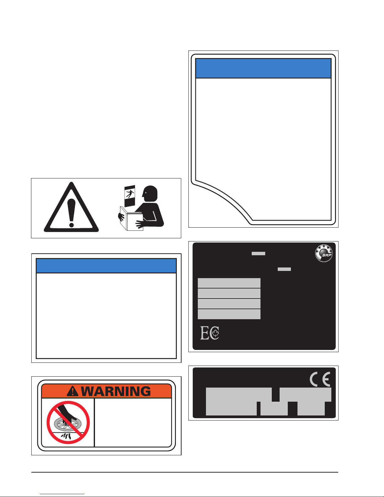
This outboard comes with hang tags and labels containing important safety information
about the operation of the outboard. Any person who operates this outboard should read
and understand this safety information.
Labels
All outboards have the following labels attached:
Warning Symbols
The following symbols are used together to indicate “CAUTION: Read the engine’s Operator’s Guide before proceeding.”
1. Read Operator’s Guide Label 355633
2. Ignition Timing Notice Label 0358045
3. Warning Label 0358046
Operator's
Guide
NOTICE
Ignition timing is set at the factory. Do NOT adjust!
Refer to the correct Service Manual for ignition
timing requirements and timing verification
procedure.
Timing pointer is NOT set at the factory and MUST
be set BEFORE making any timing adjustments.
After making any adjustments, be sure plug is
securely installed to prevent loosening during
engine operation.
P/N 358045
KEEP HANDS CLEAR!
Rotating parts
can crush and cut.
Do not operate
with guard removed.
0358046-00
4. Oil Usage Notice Label 0358210
5. Emissions Control Label 5008922
6. Serial / Model Number Label
P/N 0358210-00
This outboard has been
programmed for use of
Evinrude
®
XD50™ oil,
XD100™, or synthetic
TC-W3 NMMA-certified oil.
EVINRUDE XD100™ OIL
IS PREFERRED FOR YOUR
EVINRUDE
®
E-TEC® G2™
OUTBOARD.
Refer to the Operator's
Guide for Oil
Requirements.
NOTICE
FEL / LEF
EMISSION CONTROL INFORMATION - BRP US INC.
THIS ENGINE CONFORMS TO U.S. EPA & CALIFORNIA
EMISSIONS/EVAP REGULATIONS FOR MARINE SI ENGINES
RENSEIGNEMENTS SUR LE DISPOSITIF ANTIPOLLUTION
CE MOTEUR EST CONFORME AUX NORMES DE L'EPA DES É. - U. &
CALIFORNIENNES POUR LES MOTEURS MARINS À ALLUMAGE COMMANDÉ
ENGINE FAMILY / FAMILLE DE MOTEUR
ENGINE DISPLACEMENT / CYLINDRÉE
EMISSION CONTROL SYSTEM
SYSTÈME DE CONTRÔLE DES ÉMISSIONS
SEE OPERATOR'S GUIDE FOR MAINTENANCE SCHEDULE
AND FUEL, OIL AND SPARK PLUG SPECIFICATIONS.
VOIR LE CALENDRIER D'ENTRETIEN ET LES
SPÉCIFICATIONS D'ESSENCE, D'HUILE ET DE BOUGIE
D'ALLUMAGE DANS LE GUIDE DE L'OPÉRATEUR.
121
MOD:
SER:
kW
kg
OUTBOARD ENGINE
MOTEUR HORS-BORD
BRP US Inc.
10101 SCIENCE DRIVE
STURTEVANT, WI, U.S., 53177
BRP EUROPE N.V.
SKALDENSTRAAT 125
GENT, BELGIUM, 9042
XXXXXXXXX XXXX
XXXXXXX XXX XX
Page 15
11
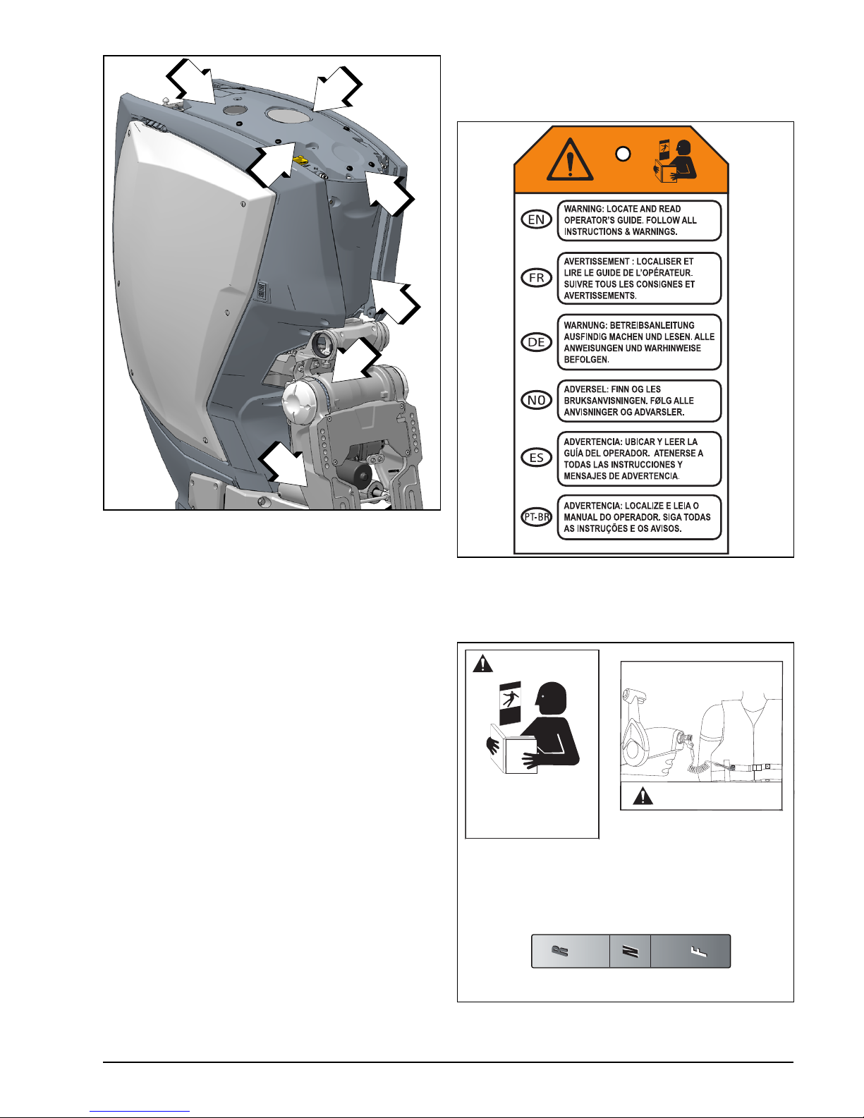
IMPORTANT ON-PRODUCT LABELS
Hang Tag
All outboards are shipped with the following
hang tag attached.
Remote Control Labels
All mechanical remote controls have the following labels attached.
Label Locations
1. Read Operator’s Guide Label
2. Ignition Timing Notice Label (remove top cover)
3. Warning Label (remove top cover)
4. Oil Usage Label (remove top cover)
5. Emissions Control Label (remove front cover)
6. Serial / Model Number Label
1
2
3
4
5
6
1
Operator's
Guide
355926
WARNING
Attach engine shut-off cord
(Lanyard) to operator.
Locate, read and
understand operator's
guide and all warnings.
Failure to do so could
result in serious injury.
Operator's
Guide
WARNING
Shift position
Reverse / Neutral / Forward
008488
Page 16
12
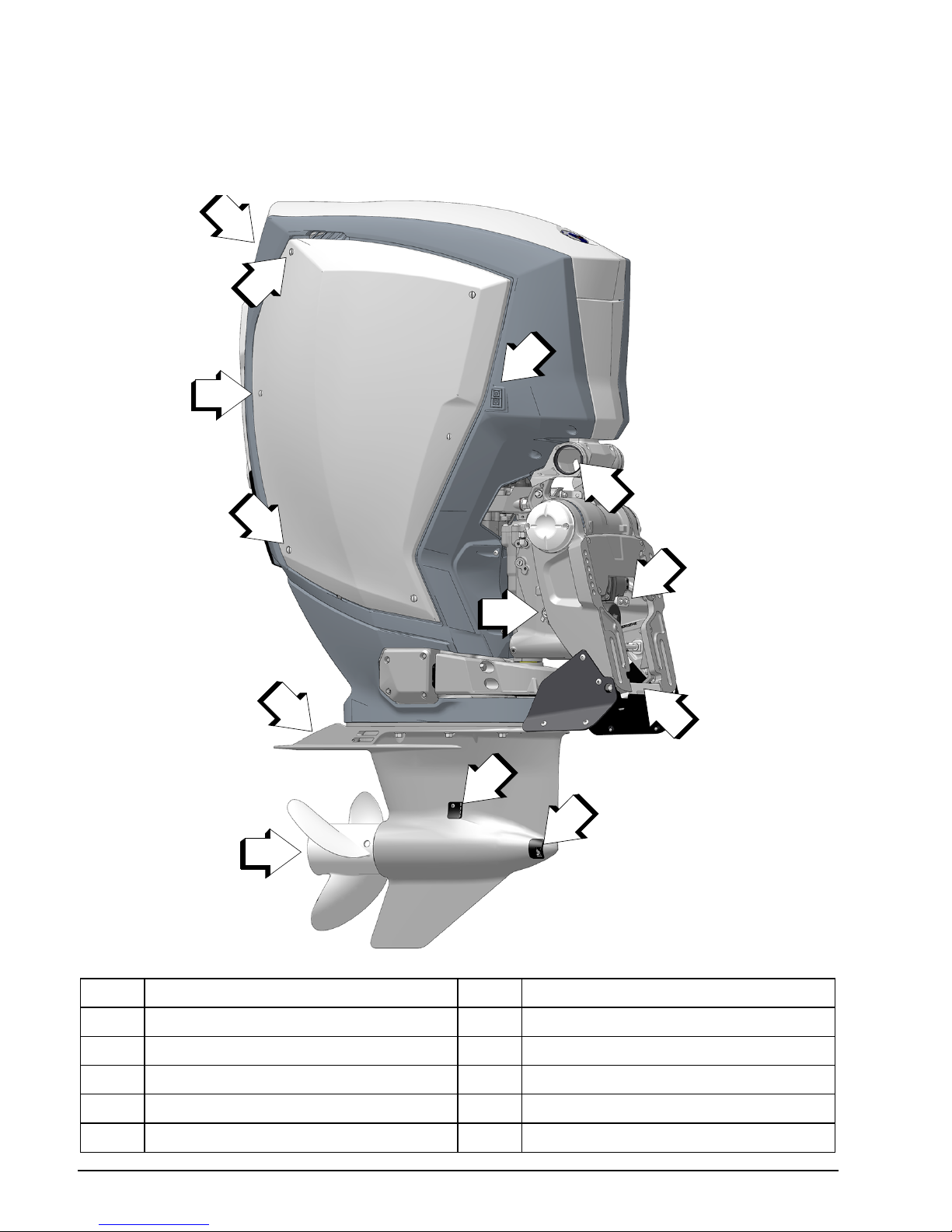
Using Your Evinrude E-TEC G2 Outboard
Component Identification
200, 225, 250, 300 HP 74° V6
NOTE: Some engine safety labels are not shown on illustrations. For information on engine
safety labels, refer to Important On-Product Labels on page 10.
Item Description Item Description
1 Air Inlet 6 Water Intake Screens
2 Cover Fasteners (6) 7 Anodes
3 Tilt Support Lever 8 Rigging Center cable entry
4 Anode 9 Trailering Tilt Switch
5 Anode
(propeller shaft)
009041
1
2
2
2
4
9
8
6
7
7
6
5
3
Page 17
13
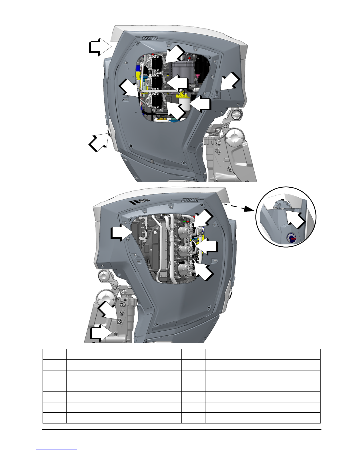
COMPONENT IDENTIFICATION 200, 225, 250, 300 HP 74° V6
Item Description Item Description
10 Water Pump Indicator, Flushing Port 16 Manual Release Valve
11 Gearcase Oil Reservoir
(Check Level) 17 Trim and Tilt Fill
12 Air Inlet 18 Fuse Box
13 Spark Plugs 19 Top Cover Latch
14 Fuel Filter 20 Spark Plugs
15 Trailering Tilt Switch
Starboard
009042
10
13
12
13
13
11
15
14
009043
009082
Port
19
18
20
20
20
17
16
Page 18

14
Using Your Evinrude E-TEC G2 Outboard
2–Stroke Engine Oil and Fuel
2–Stroke Engine Oil Requirements
Evinrude Brand Oils
Evinrude XD 2–stroke outboard oils are formulated to give best engine performance
while controlling piston and combustion
chamber deposits, providing superior lubrication, and ensuring maximum spark plug life.
The following 2–stroke outboard oils are recommended for use in your Evinrude E-TEC
G2 outboard:
• Evinrude XD100 Direct Injection Oil
• Evinrude XD50 2–Stroke Oil
• or a synthetic TC-W3 NMMA-certified oil
Evinrude XD100 oil is preferred for your
Evinrude E-TEC G2 outboard. This synthet-
ic formula oil provides uncompromised lubrication and superior performance, even in
extreme conditions especially in cold temperatures down to 0°F (-17°C).
Failure to follow oil specifications could void
the engine warranty if a lubrication-related
failure occurs.
Oiling System information
If a “LOW OIL” warning occurs, you have a
limited amount of time of normal operation before running out of oil. Refill the oil tank with
approved oil as soon as possible.
Refer to Engine Monitoring on page 30.
To check oil level:
• Trim outboard to the vertical position.
• Use a digital display or gauge to check the
oil tank level.
Always “top off” your oil tank prior to prolonged usage or long trips. You may want to
keep an extra supply of outboard oil in the
boat.
New outboards are programmed to use additional oil during the first two hours of operation
above 2000 RPM.
If you run the oil tank empty, REFILL the oil
tank and prime the oil system before using the
engine. Refer to Filling the On-Engine Oil
Tank on page 15 and Priming the Oil System on page 15.
If an accessory remote oil tank is installed and
the oil hose is disconnected for any reason,
seal it to prevent spillage. Install a cap on the
hose fitting to prevent contamination.
Oil Tank Capacity
The on-engine oil tank capacity is 2.0 gallons
(7.5 liters).
Optional Remote Oil Tank
The following optional accessory remote oil
tank kits are available:
• 1.8 gallons (6.8 liters)
• 3.0 gallons (11.3 liters)
• An oil tank pick-up kit is also available for
the 10 gallon (37.8 liters) capacity oil tank.
Install the optional remote oil tank following
the instructions provided with the unit.
NOTICE
When operating in conditions under 32°F
(0°C), Evinrude XD100 oil must be used.
NOTICE
DO NOT add automotive type 4–stroke
oils to 2–stroke engine oil tank(s).
Do not add oil to the fuel.
Page 19
15
2–STROKE ENGINE OIL AND FUEL
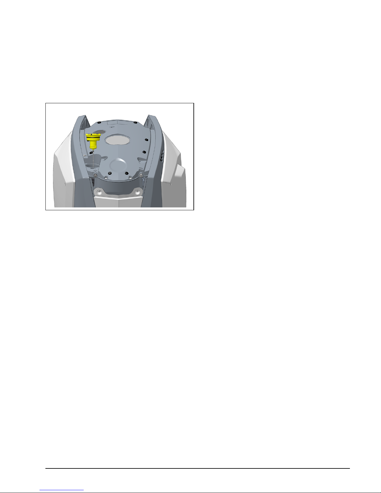
Filling the On-Engine Oil Tank
Remove the top cap of the engine cover.
Next, remove the oil fill cap. Fill the oil tank
with outboard lubricant. Oil capacity is 2 gallons (7.5 liters)
Replace the filler cap and tighten securely. If
you run the tank empty, you MUST prime the
oil system before using the engine.
Priming the Oil System
The oil system of Evinrude E-TEC G2 outboards is primed at the factory.
Priming the oil system is only required if:
• The oil system is disassembled for service
or parts replacement; or
• The oil tank is run out of oil.
NOTE: If the oil tank is run out of oil, the EMM
will activate SHUT DOWN mode and set Fault
Code 33. See “NO OIL” on page 31.
After refilling an empty oil tank or servicing the
oil system, air MUST be removed from the oil
system before operating the outboard.
Prime the oil system by performing the Long-
Term Storage (Winterization) on page 44
TWO times.
If available, Evinrude Diagnostic software
v 6.1 or higher may be used to prime the oil
system ONE time.
Oil Fill Cap 009044
Page 20

16
Using Your Evinrude E-TEC G2 Outboard
Fuel Requirements
Fuel blending varies by country and region.
Your outboard has been designed to operate
using the recommended fuels; however, be
aware of the following:
• The boat’s fuel system may have different
requirements regarding the use of alcohol
fuels. Refer to the boat’s owner guide.
• Alcohol blended fuels attract and hold moisture which may lead to fuel phase separation and can result in engine performance
problems or engine damage.
• Use of fuel containing alcohol above the
percentage specified by government regulation can result in the following problems in
outboard engines and fuel system components:
• Vapor lock or fuel starvation
• Starting and operating difficulties
• Deterioration of rubber or plastic parts
• Corrosion of metal parts
• Damage to internal engine parts
• Have your dealer inspect for fuel leaks or
other fuel system abnormalities if you suspect the presence of alcohol in gasoline exceeds the current government regulation
limits.
Recommended Fuel: Use unleaded gasoline with an AKI (R+M)/2 octane rating of 87,
or an RON octane rating of 90.
Use in North America
The use of unleaded gasoline containing alcohol above the percentage specified by government regulations is not recommended.
Use of fuel labeled E15 is prohibited by U.S.
EPA Regulations.
Use of a boat mounted water separating fuel
filter is strongly recommended.
Use Outside North America
The use of unleaded gasoline containing alcohol above the percentage specified by local
government regulations is not recommended.
Use of a boat mounted water separating fuel
filter is strongly recommended.
Fuel System Information
In the United States, the U.S. EPA requires
low permeability fuel hose, fuel primer bulbs,
portable fuel tanks and fuel caps to be used
with outboard engines.
IMPORTANT: Fuel distribution hoses in the
boat must deliver fuel at a specific flow rate.
Minimum inside diameter of fuel hoses must
be 3/8 in. (9 mm).
Fuel systems with built-in tanks, particularly
those that include antisiphon valves and filter/
primer units, may have restrictions not allowing the engine fuel pump to deliver sufficient
fuel under all conditions. This can result in a
loss of performance. If a performance problem exists, see the Service Note on page 48.
WARNING
Gasoline is extremely flammable and
highly explosive under certain conditions. Follow the instructions in this section explicitly. Improper handling of fuel
could result in property damage, serious
injury or death.
Leaking fuel is a fire and explosion hazard. All parts in the fuel system should
be inspected frequently and replaced if
signs of deterioration or leakage are
found. Inspect the fuel system each time
you refuel, each time you remove the
engine cover and annually.
NOTICE
Always use fresh gasoline. Gasoline will
oxidize; the result is loss of octane, volatile compounds, and the production of
gum and varnish deposits which can
damage the fuel system.
NOTICE
Do NOT use fuel from fuel pumps
labeled E85. Never experiment with other
fuels.
Page 21

17
2–STROKE ENGINE OIL AND FUEL
Fuel Hose Connections
1) If the fuel hose is disconnected for any reason, seal the hose and fitting to prevent
spillage. or contamination.
2) Connect the fuel hose to the 3/8 in. (9 mm)
fuel fitting. Fasten hose securely with the
18.5 mm clamp from owner’s kit.
Fueling Procedure
Do NOT add 2–stroke engine oil to the fuel.
On a Trailer
1) Make sure the boat is level.
2) Slowly turn the fuel tank cap counterclockwise to remove it.
3) Insert the gas pump nozzle into the filler
neck of the fuel tank and fill the fuel tank.
4) Stop filling immediately when the automatic shut-off feature of the gas pump handle
activates.
5) Wait a moment before removing the gas
pump nozzle from the filler neck. Do not retract the gas pump nozzle from the filler
neck to top off the fuel tank.
6) Install the fuel tank cap and turn clockwise
to fully tighten it.
In the Water
1) Turn off engine.
2) Tie boat securely to the fueling pier.
3) Do not allow anyone to remain in or on the
boat.
4) Have a fire extinguisher close at hand.
5) Slowly turn the fuel tank cap counterclockwise to remove it.
6) insert the gas pump nozzle into the filler
neck of the fuel tank and fill the fuel tank.
7) Stop filling immediately when the automatic shut-off feature of the gas pump handle
activates.
8) Wait a moment before removing the gas
pump nozzle from the filler neck. Do not retract the gas pump nozzle from the filler
neck to top off the fuel tank.
Install fuel tank cap and turn clockwise to fully
tighten it.
WARNING
Fuel is flammable and explosive under
certain conditions. Follow these instructions to ensure safety when handing
fuel:
• Always work in a well ventilated area.
• Always turn off the engine before fueling.
• Never permit anyone other than an
adult to refill the fuel tank.
• Do not smoke, or allow open flames, or
sparks or use electrical devices such as
cellular phones in the vicinity of a fuel
leak or while fueling.
• When fueling, keep boat level.
• Remove portable fuel tanks from the
boat before fueling.
• Fuel tank may be pressurized, turn cap
slowly when opening.
• Do not overfill or top off the fuel tank
and leave boat in the sun. As temperature increases, fuel expands and might
overflow.
• To prevent fuel back-flow, fill the fuel
tank slowly so air can escape from tank.
• Always wipe off any fuel spillage.
ENVIRONMENTAL NOTE
Dispose of fuel contaminated towels in an
environmentally responsible manner, or according to local regulations.
Page 22

18
Using Your Evinrude E-TEC G2 Outboard
Fuel Additives
The only fuel additives approved for use in
your Evinrude E-TEC G2 outboard are:
• Evinrude 2+4 Fuel Conditioner
• Evinrude Fuel System Cleaner
Evinrude 2+4 Fuel Conditioner will help prevent gum and varnish deposits from forming
in fuel system components and will remove
moisture from the fuel system. It can be used
continuously and should be used during any
period when the outboard is not being operated on a regular basis. Its use will reduce spark
plug fouling, fuel system icing, and fuel system component deterioration.
Evinrude Fuel System Cleaner will help keep
fuel injectors in optimal operating condition.
Fuel System Priming
If the outboard is run out of fuel, refill the fuel
tank. Turn the key switch to the ON position to
activate the fuel pump.
NOTICE
Use of other fuel additives can result in
poor performance or engine damage.
Page 23
19
Operation
Safety Information Engine Starting / Stopping
Refer to the Pre-Ride Inspection on page 35.
Complete the inspection before using your
Evinrude E-TEC G2 outboard.
Be sure the water intake screens are below
the water surface.
Engine Cut–off Switch/Key Switch
A combination engine cut–off switch and key
switch is a feature of Evinrude prewired remote controls and all Evinrude control wiring
kits. Use of the engine cut–off switch feature
is highly recommended on all boats.
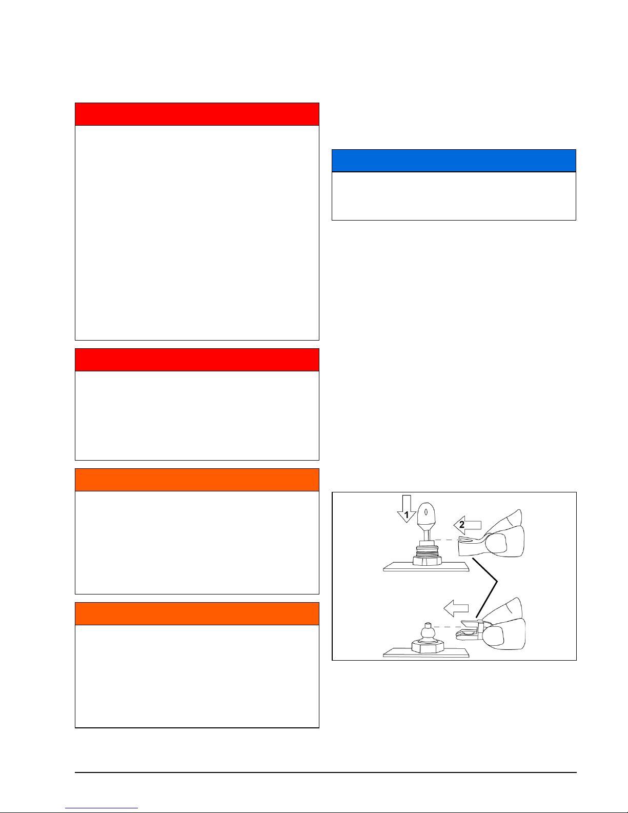
Connect the clip to the engine cut–off switch/
key switch.
If boat is equipped with a second station, connect the clip to the second station cut–off
switch.
IMPORTANT: The second station clip MUST
be installed. The outboard cannot be started if
the second station clip is not in place.
DANGER
Serious injury or death can result from
contact with a rotating propeller or moving boat and outboard.
Propeller blades can be sharp and the
propeller can continue to turn even after
the engine is off.
Assure the engine propeller area is clear
of people and objects before starting
engine or operating the boat.
Be alert of people in the water.
Always shift the outboard to NEUTRAL
and shut off the engine immediately
when your boat is in an area where there
might be people in the water.
DANGER
DO NOT run the engine indoors or without adequate ventilation or permit
exhaust fumes to accumulate in confined
areas. Engine exhaust contains carbon
monoxide which, if inhaled, can cause
serious brain damage or death.
WARNING
The engine cover is a machinery guard.
DO NOT operate your outboard with the
cover off unless you are performing
maintenance. Be careful to keep hands,
hair, and clothing clear of all moving
parts. Contact with moving parts could
cause injury.
WARNING
Be familiar with the waters you are operating in. The gearcase of this outboard
extends below the water surface and
could potentially come in contact with
underwater obstructions. Contact with
underwater obstructions may result in
loss of control and personal injury.
NOTICE
You MUST supply water to the engine
before attempting to start it. Engine damage can occur quickly.
1. Clip
2. Engine cut–off switch/key switch
3. Second station cut-off switch
009045
123
Page 24
20
Using Your Evinrude E-TEC G2 Outboard
In an emergency situation, the engine can be
started without the clip installed on the key
switch. Follow the normal starting procedure.
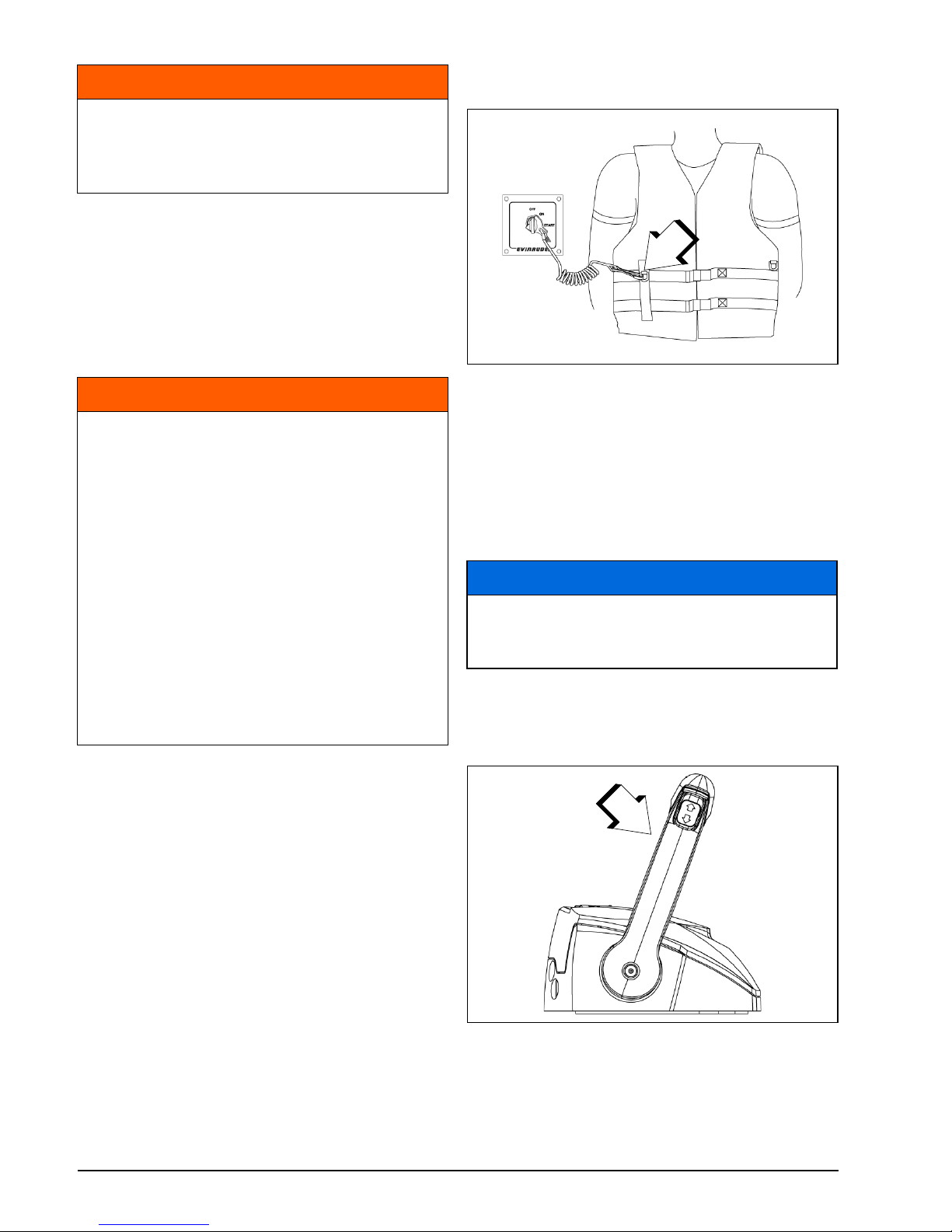
Reinstall a clip as soon as possible. The op-
erator should always use the clip and tether cord anytime the engine is running.
Refer to Engine Cut–off Switch/Key Switch
on page 19.
IMPORTANT: Your engine cut–off switch can
be effective only when in good working condition. At each outing, inspect clip and tether
cord for cuts, breaks, or wear. Replace worn
or damaged parts.
Snap the tether cord to a secure place on the
operator’s clothing or life vest — not where it
might tear away instead of activating the engine cut–off switch.
Disconnecting the clip and tether cord will
stop the engine and prevent the boat from becoming a runaway if the driver moves beyond
the range of the tether cord. If the tether cord
is too long, it can be shortened by knotting or
looping it. DO NOT cut and retie the tether
cord.
Move the remote control handle to NEUTRAL.
Set control to SLOWEST speed position.
DO NOT advance the throttle before start-up.
Advancing the throttle overrides the electronic
idle control system.
WARNING
Always use the tether cord when operating your boat to help prevent a runaway
boat and reduce the risk of personal
injury or death
WARNING
Avoid knocking or pulling the clip off the
engine cut–off switch during normal
boating. Avoid bumping the key if operating without the clip on the switch. The
resulting unexpected loss of forward
motion can throw occupants forward,
causing injury.
Keep the tether cord free from obstructions and entanglements.
At each outing, test the system’s operation. With the engine running, remove
the clip from the switch by pulling the
tether cord. If the engine does not stop
running, see the Service Note on page
45.
1. Tether cord
009046
NOTICE
Carefully check the function of all control and engine systems before leaving
the dock.
1. SLOWEST speed position
009047
1
1
Page 25
21
OPERATION
If the outboard is started with the throttle advanced, the outboard will be in a safety mode.
It will not respond to throttle until the throttle is
returned to slowest IDLE position
After the engine starts, the engine management module (EMM) automatically increases
idle speed slightly. Idle speed will decrease as
the engine warms up.
Engine Starting
IMPORTANT: If equipped with Evinrude
ICON II Remote Control System, refer to Re-
mote Controls — Evinrude ICON II Control
System on page 23.
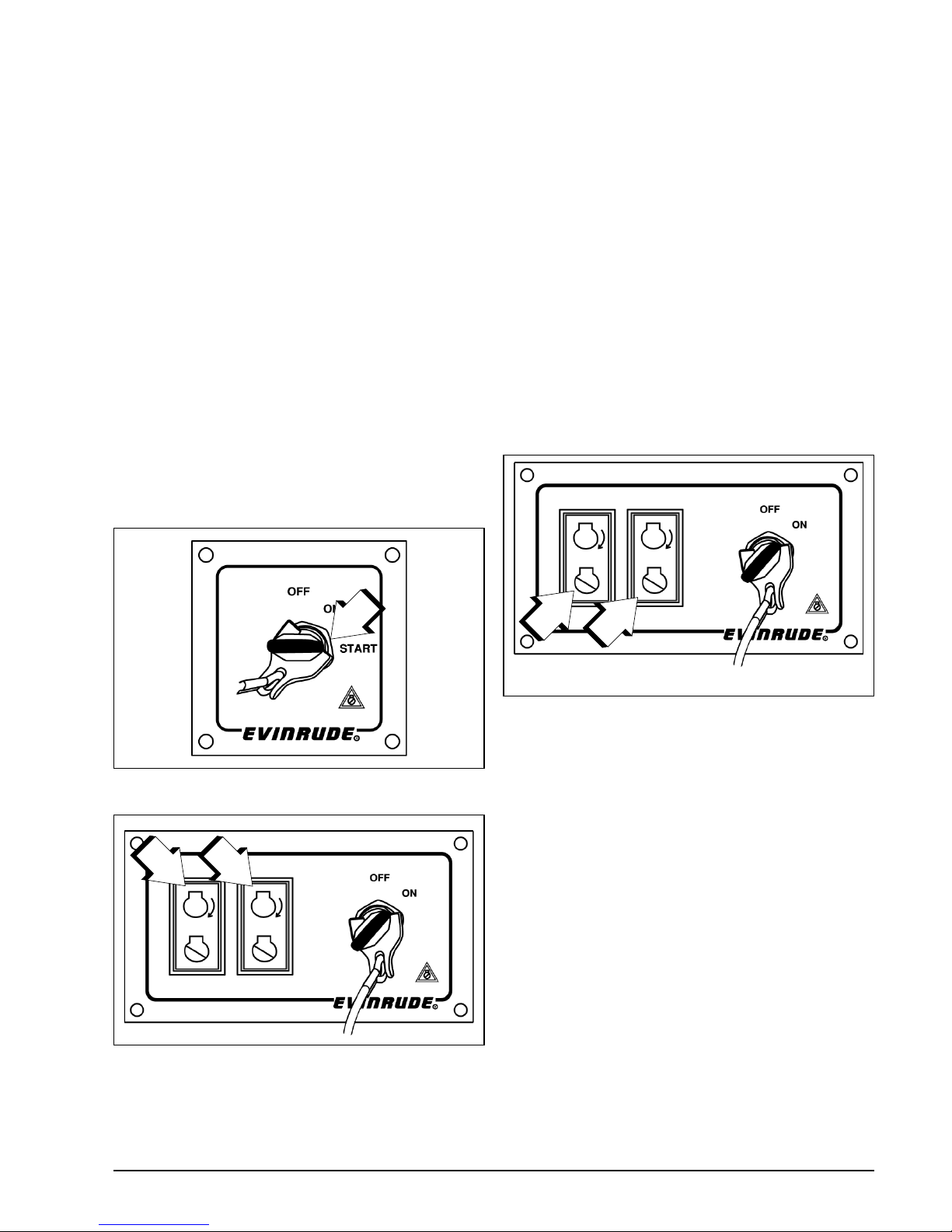
Turn the key switch to the on position, then:
Single engine applications — turn the key ful-
ly clockwise to the START position.
Multiple engine applications — Push and hold
the START button(s).
Upon start-up, release the key or buttons.
If the engine did not start, release the key or
button momentarily, then try again.
Each time the key switch is turned from OFF
to ON, the warning system will self-test. Refer
to Engine Monitoring on page 30.
If your outboard does not react normally to
this starting procedure or if it fails to start, refer to Troubleshooting on page 46.
After Engine Starts
The engine monitoring system will alert you of
any abnormalities.
Engine Stopping
Move control handle to NEUTRAL.
Multiple engine applications — Briefly push
the STOP buttons.
1. Key switch START position
009048
1. Start buttons
009158
1
1
1
1. Stop buttons
009158
1
1
Page 26
22
Using Your Evinrude E-TEC G2 Outboard
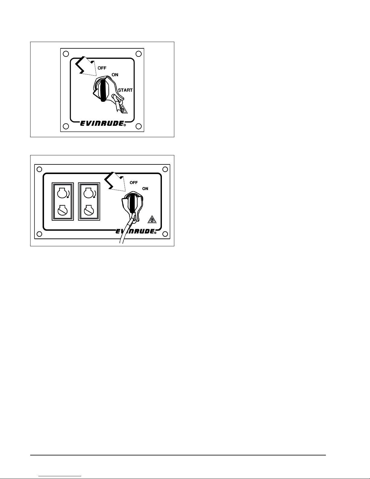
All applications — Or turn key switch coun-
terclockwise to the OFF position.
Remove the key when the boat will be unattended.
1. Key switch, OFF position
009049
1. Key switch, OFF position
009159
1
1
Page 27
23
OPERATION
Remote Controls — Evinrude ICON II Control System
ICON II User’s Guide
IMPORTANT: For complete information
about using ICON II remote control systems,
refer to the “ICON II User’s Guide”.
Remote Control Selection
Evinrude ICON II is an intelligent, electronic
shift and throttle control system for use with
Evinrude E-TEC G2 outboards. ICON II control systems are available for up to four–engine installations. The ICON II control system
supports dual station and “flying bridge” applications.
ICON II Remote Control Features
Shifting
With engine running and control handle in
NEUTRAL:
Move the control handle forward or aft until it
engages the forward or reverse gear detent.
Speed Control
After gear engagement, move the control
handle slowly in the same direction to increase speed.
Press the RPM + or – button to fine tune engine speed up or down in 1% increments.
Engine Synchronization (Dual
Binnacle Only)
Press the SYNC button to automatically synchronize the RPM of multiple engines. The
SYNC button also transfers control of all engines to the port lever on the control.
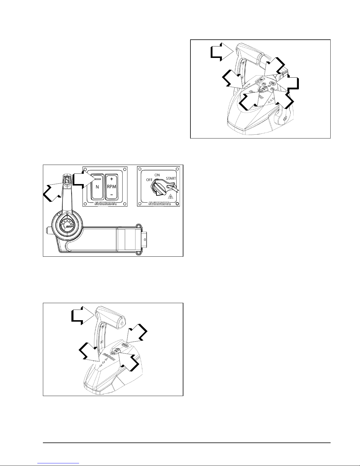
Concealed Side Mount ICON II Control
1. Trim/tilt switch
2. RPM switch panel
3. OFF/ON/START switch
4. NEUTRAL Indicator LED
009052
Single Binnacle ICON II Control
1. Trim/tilt switch
2. Gear position indicators
3. Neutral button
4. RPM Tune button
009053
2
3
1
4
2
3
1
4
Dual Binnacle ICON II Control
1. Master Trim/tilt switch
2. Gear position indicators
3. Individual engine trim switches
4. SYNC button
5. Mode button
6. RPM Tune button
009054
2
1
3
6
4
5
Page 28
24
Using Your Evinrude E-TEC G2 Outboard
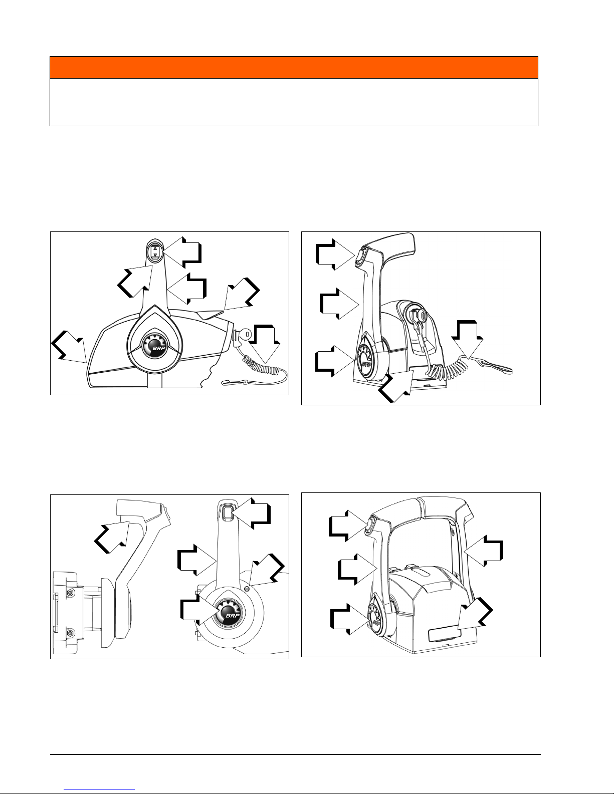
Remote Controls - Evinrude Mechanical Controls
Use of a mechanical remote control requires an accessory mechanical to digital shift and throttle converter.
IMPORTANT: When selecting the remote control system for your boat, specify Evinrude com-
ponents. Evinrude controls incorporate safety and convenience features as:
• Start-in-gear prevention
• Plug-in compatibility with Evinrude Modular Wiring System (MWS)
WARNING
If you choose a non-Evinrude remote control, it must have a start-in-gear prevention
feature. This feature can prevent injuries resulting from unexpected boat movement
when the engine starts.
Side Mount Control 006448
1. Handle – shift and throttle
2. Trim/tilt switch (where equipped)
3. Neutral lock lever
4. Fast idle lever (warm-up)
5. Throttle friction adjusting screw
6. Engine cut–off switch clip and tether cord
Concealed Side Mount Control 006447
1. Handle – shift and throttle
2. Trim/tilt switch (where equipped)
3. Neutral lock lever
4. Fast idle button (warm-up)
5. Throttle friction adjusting screw
4
3
2
5
1
6
3
2
1
4
5
Single Lever Binnacle Mount Control 006446
1. Handle – shift and throttle
2. Trim/tilt switch (where equipped)
3. Fast idle button (warm-up)
4. Throttle friction adjusting screw (under cover)
5. Engine cut–off switch clip and tether cord
Dual Lever Binnacle Mount Control 006445
1. Handle – shift and throttle
2. Trim/tilt switch (where equipped)
3. Fast idle button (warm-up)
4. Throttle friction adjusting screw (under cover)
4
3
1
5
2
2
1
3
4
1
Page 29
25
OPERATION
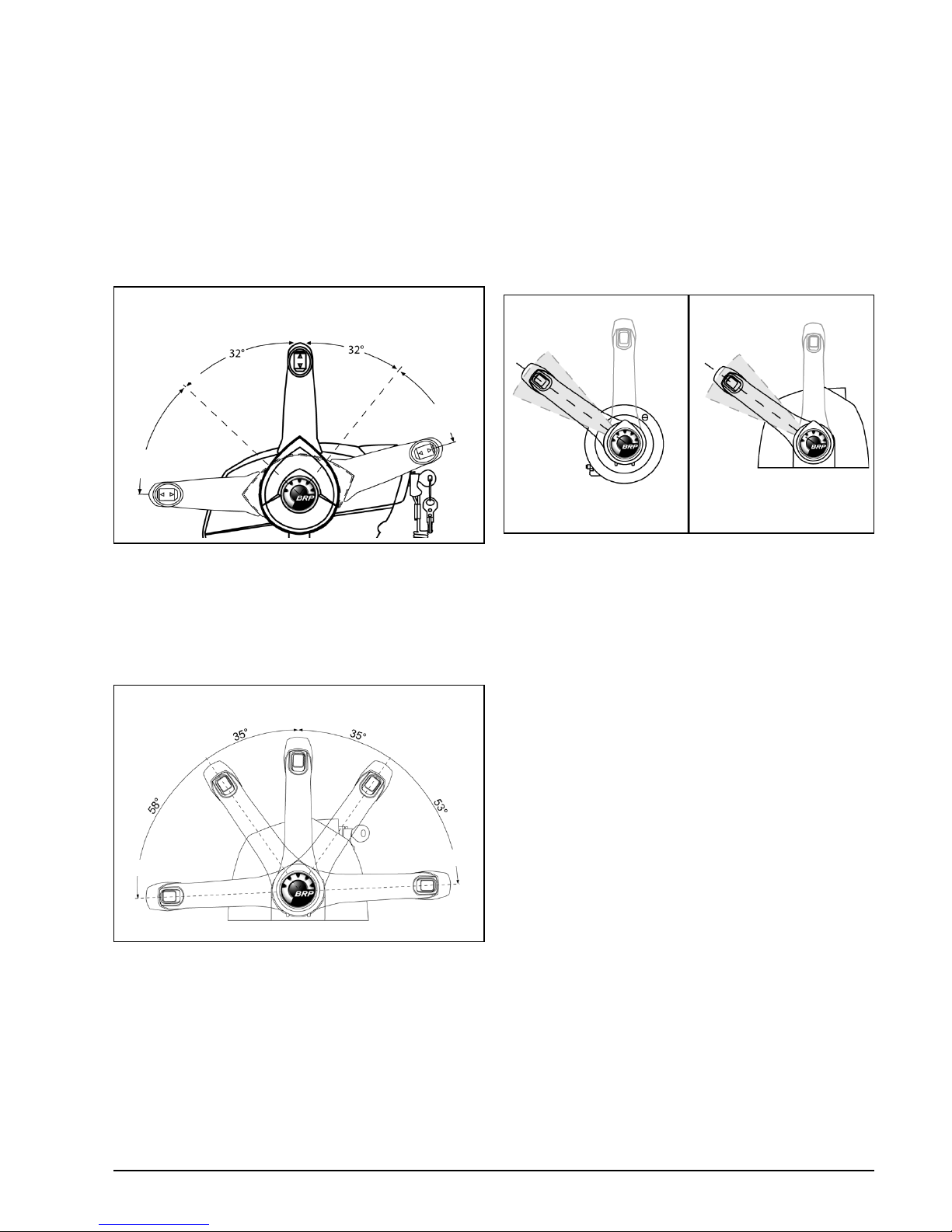
Shifting
With engine running and control handle in
NEUTRAL:
Side Mount Controls
Unlock the control handle by lifting the neutral
lock lever on the hand grip. Move the control
handle with a firm, quick motion, forward or aft
until it engages the forward or reverse gear
detent.
Binnacle Mount Controls
Move the control handle with a firm, quick motion, forward or aft until it engages the forward
or reverse gear detent.
Speed Control
After gear engagement, move the control
handle slowly in the same direction to increase speed.
Fuel Economy
Fuel economy can vary depending on boat
load, hull design, and throttle setting. When
boat reaches top speed, throttle back from
FULL SPEED to a lower throttle setting. You
can save fuel with a minimal loss of speed.
If equipped, use the “fuel economy” feature of
digital displays or gauges to optimize fuel consumption. Refer to the user’s guide for the
digital display.
004854
005502
FORWARD
REVERSE
REVERSE
FORWARD
NEUTRAL
FORWARD
FORWARD
REVERSE
REVERSE
NEUTRAL
Typical Fuel Economy Throttle Range 008490
1. Side mount control
2. Binnacle mount control
1
2
Page 30
26
Using Your Evinrude E-TEC G2 Outboard
Trim, Tilt and Steering
Power Trim and Tilt
The trim and tilt functions of Evinrude E-TEC G2 outboards are controlled by the engine EMM.
IMPORTANT: Activating any trim button while the key switch is in the OFF position will briefly
turn on the system. This will cause the electric fuel pump to run and the remote control and
any displays or gauges to turn on. There will be a short delay before the trim system operates.
This is normal. The system will turn off after a few seconds of non-use.
Some boats plow, or are difficult to plane, when operated in the lowest trim position. If your
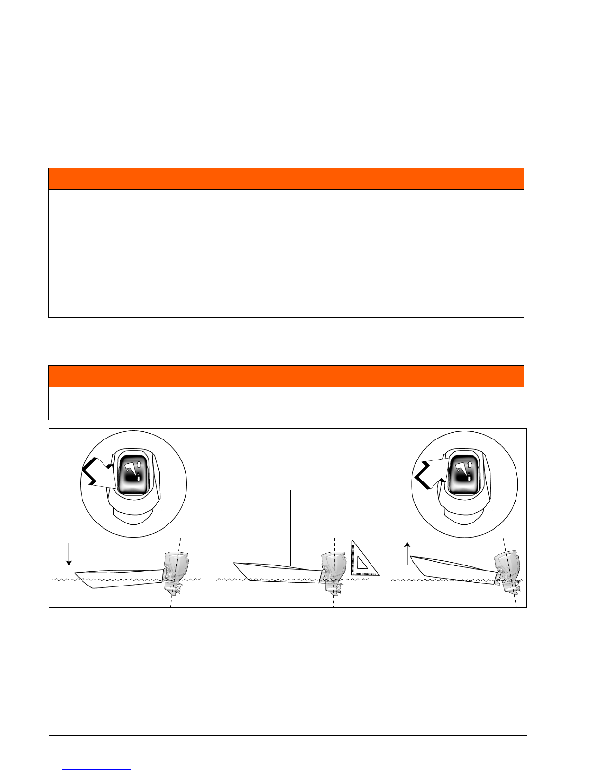
boat handles unsuitably when trimmed fully bow-down, adjust the trim.
The boat should accelerate quickly, plane easily, and run parallel to the surface of the water
at high speeds.
• If trim position is too LOW the front of boat will be DOWN and push water.
• If trim position is too HIGH the front of boat will be UP and bounce.
WARNING
When operating in rough water or crossing a wake, excessive bow-up trim may result
in the boat’s bow suddenly rising skyward, possibly ejecting or otherwise seriously
injuring occupants.
Some boat/outboard/propeller combinations may encounter boat instability and/or
high steering torque when operated at high speed at or near the outboard’s trim
range limits (full bow-up or bow-down). Boat stability and steering torque can also
vary due to changing water conditions. If any adverse conditions occur, reduce throttle and/or adjust trim angle to maintain control. If you experience boat instability and/
or high steering torque, see your Dealer to correct these conditions.
WARNING
If the bow of the boat plows the water at high speeds, the boat may bow steer or spin
suddenly, possibly ejecting or otherwise seriously injuring occupants.
1. Parallel to the surface of the water
2. Trim switch, DOWN
3. Trim switch, UP
009055
1
231
2
1
Page 31
27
TRIM, TILT AND STEERING
i-Trim
Your outboard is equipped with i-Trim, a trim
assist feature. By default, this feature is disabled from the factory.
Use the Evinrude ICON-Touch or ICON CS
digital display to enable i-Trim. If your boat is
not equipped with an ICON digital display,
your Dealer must use Evinrude Diagnostic
software to enable this feature.
To activate the i-Trim:
• the key switch must be in the ON position
• use the trim/tilt switch to trim the engine to
the full DOWN position.
During operation, the outboard will automatically trim up or down to an acceptable trim angle based on pre-programmed parameters.
Use the trim/tilt switch on the control lever to
fine tune to an optimum trim angle.
IMPORTANT: Use of the trim/tilt switch to
manually adjust the outboard trim angle will
temporarily deactivate i-Trim.
To reactivate i-Trim:
• use the trim/tilt switch to trim the engine to
the full down position
• bring the engine to idle speed.
Trim
In most operating conditions, it is recommended to trim the outboard to the full down
position while accelerating. As the boat
comes on plane, trim the outboard up for best
performance.
Run the boat in the water to determine the
best trim angle.
Over-trimming increases engine RPM while
decreasing speed. The best trim setting is
when the highest speed is achieved with the
lowest engine RPM.
IMPORTANT: Weight distribution can affect
the performance of the boat. Distribute weight
evenly in the boat.
Trim Angle Adjustment
Use the trim/tilt switch to adjust the outboard
position in the tilt range or trim range.
Shallow Water
Adjust the outboard position within the tilt
range for shallow water operation.
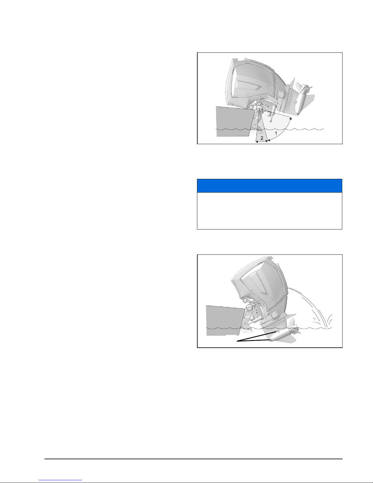
Tilt
The tilt range allows the operator to tilt the
outboard for clearance when beaching, mooring, launching, or trailering.
Tilt Limit
See Adjustments on page 55, if your outboard contacts the boat’s motor well while tilting.
1. Tilt range
2. Trim range
009056
NOTICE
When operating a tilted outboard, do not
run above a fast idle speed. Keep the
water intakes submerged at all times to
prevent the engine from overheating.
1. Water intakes
009057
1
Page 32
28
Using Your Evinrude E-TEC G2 Outboard
Manual Release Valve
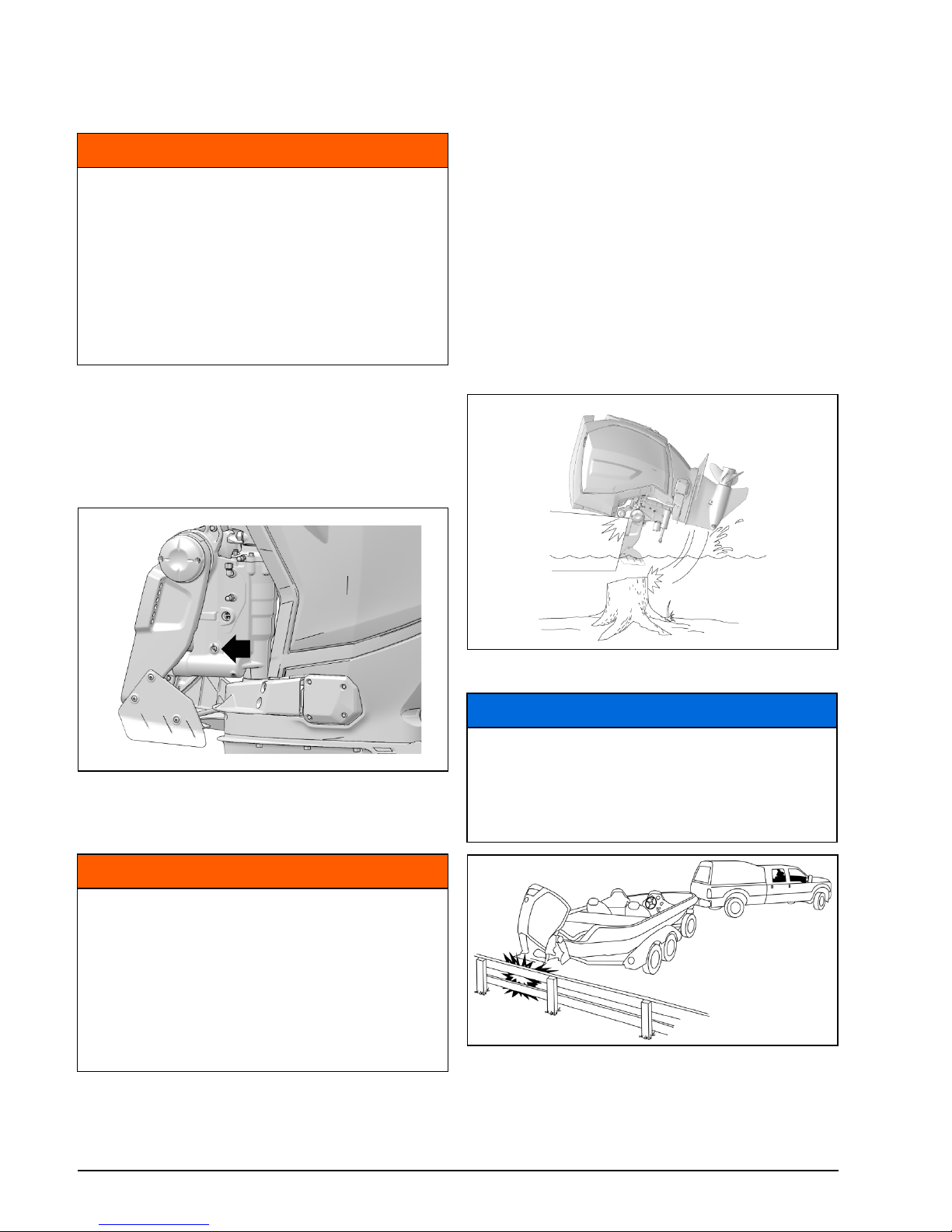
If needed, the outboard will tilt up or down
manually, using the manual release valve.
1) Turn the manual release screw counterclockwise, slowly (about 3 1/2 turns), until
it lightly contacts its retaining ring.
2) Reposition the outboard.
3) Tighten the manual release valve to hold
the outboard in its new position.
Impact Damage Protection
Your outboard has a shock absorption system
designed to help withstand damage from im-
pact with underwater objects at low to moderate speeds.
Such impacts can result in serious damage to
your outboard or boat. Occupants can also be
ejected or injured by falling against portions of
the boat as a result of rapid deceleration following impacts.
When boating in unfamiliar, shallow, or debris-laden waters, seek information on safe
boating areas and navigation hazards from a
reliable local source. Reduce your speed and
keep a sharp lookout!
IMPORTANT: Impact damage is NOT covered by the outboard warranty.
If you hit any object:
• STOP immediately and examine the outboard for loosening of attaching hardware.
WARNING
Keep everyone clear of a tilted outboard
when backing out the manual release
screw. The outboard could drop suddenly and forcibly. Be sure to tighten the
manual release screw after manually
repositioning the outboard. Tightening
the screw also reactivates the outboard’s
impact protection and reverse thrust
capability.
Manual Release Screw 009059
WARNING
Any malfunction of the power trim and
tilt unit could result in loss of shock
absorber protection if an underwater
obstruction is hit. Malfunction can also
result in loss of reverse thrust capability.
Correct fluid level must be maintained to
ensure operation of the impact protection on this unit.
009060
NOTICE
The outboard’s shock absorption system
does not work while operating in
reverse. If you back into an object, either
in the water or while trailering, your boat
and outboard can be seriously damaged.
009061
Page 33

29
TRIM, TILT AND STEERING
• INSPECT for damage to swivel and stern
brackets, and steering components.
• EXAMINE the boat for structural damage.
• TIGHTEN any loosened hardware.
If the collision occurred in the water, proceed
slowly to harbor. Before boating again, have
your Dealer thoroughly inspect all components.
If your engine will not trim to the fully DOWN
position, it may have impacted an underwater
object. See the Service Note on page 48.
Dynamic Power Steering (DPS)
Your outboard may be equipped with Dynamic Power Steering (DPS). DPS offers three
power steering assist levels.
Power Steering Assist Levels
All power steering assist levels provide the
same rate of assist at engine speeds below
4500 RPM.
As engine speed increases above 4500 RPM,
assist levels progressively decrease.
The factory default assist level is “Minimum”.
Use the Evinrude ICON-Touch or ICON CS
digital display to change the power steering
assist level to “Medium” or “Maximum”.
If your boat is not equipped with an ICON digital display, your Dealer must use Evinrude
Diagnostic software to change the power
steering assist level.
WARNING
Failure to inspect for damage after an
accident or striking an object could
result in sudden, unexpected component
failure, loss of boat control, and personal
injury. Unrepaired damage could reduce
your boat and outboard’s ability to resist
future impacts.
WARNING
Selection of power steering assist level
is a matter of operator preference.
Be aware that changing the power steering assist level can affect boat handling.
After changing the level of power steering assist, operate the boat with care to
become familiar with any changes in
boat handling characteristics.
Page 34
30
Using Your Evinrude E-TEC G2 Outboard
Engine Monitoring
IMPORTANT: Your outboard must be
equipped with an engine monitoring system
such as Evinrude ICON Touch, ICON, I-Com-
mand, or other NMEA 2000 compliant CANbus instruments.
An analog SystemCheck gauge, or equivalent
may be used. Analog gauges REQUIRE the
installation of a digital to analog converter.
The engine monitoring system provides engine operating information and alerts you of
abnormal conditions that could damage your
outboard. The monitoring system consists of
a dash-mounted display or gauge, a warning
horn, sensors on the engine and oil tank, and
related wiring.
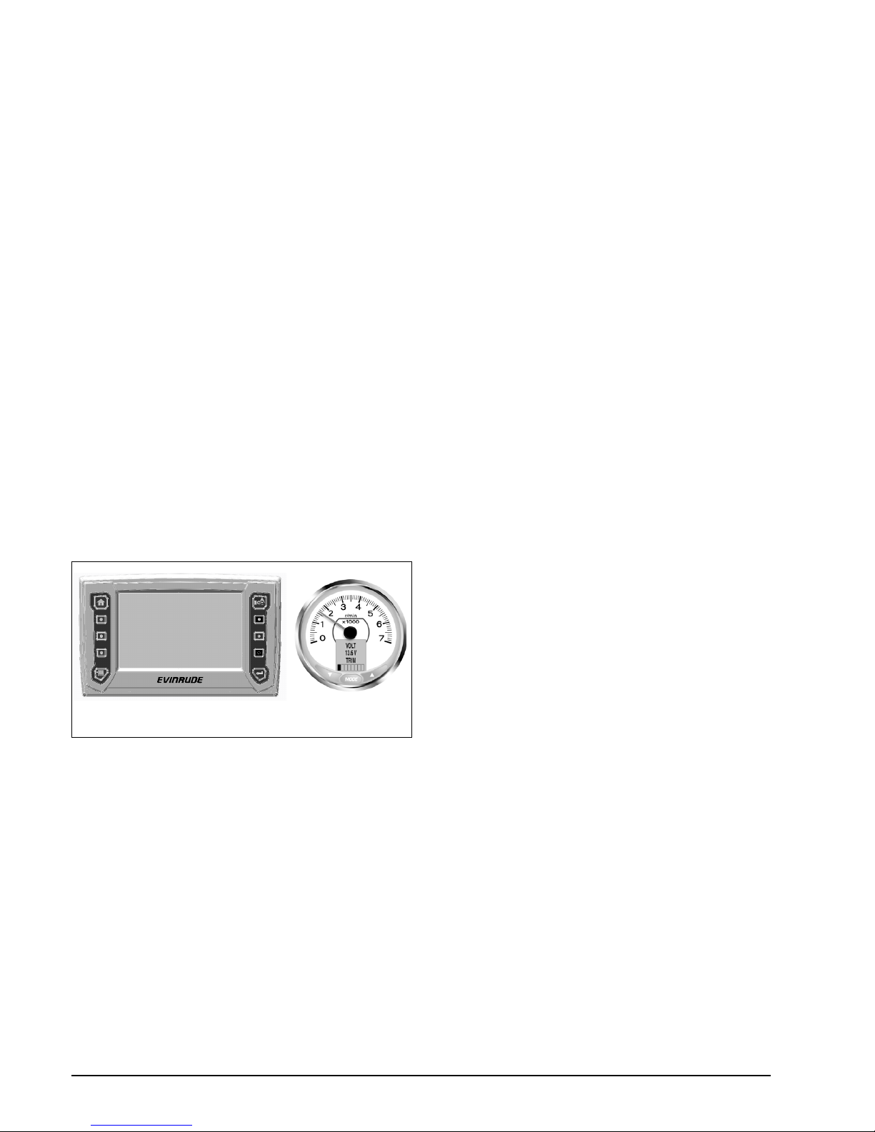
Displays and Gauges
Gauges and displays are available in several
styles, such as a Evinrude ICON Touch,
ICON Pro with digital LCD display or a basic
SystemCheck gauge.
Refer to the display or gauge user’s guide for
operation, warnings, and monitoring instructions.
System Self-Test
During engine start-up, pause with the key
switch in the ON position. Digital displays and
gauges will self test as follows:
Evinrude ICON Touch — The digital touch
screen displays a “booting” screen, followed
by the Evinrude logo and then the default
home page.
ICON —The ICON gauge sounds a beep.
The tachometer and speedometer LCD
screens display SELF TEST MODE IN OPERATION. When the self test is complete, the
gauges will beep a final time and then display
SELF TEST COMPLETE!
I-Command —The I-Command system dis-
plays the Evinrude welcome screen, followed
by the tachometer display.
SystemCheck —The SystemCheck monitor
sounds a beep. The SystemCheck gauge indicator lights turn on simultaneously, then off
in sequence.
Engine Monitor Warnings
Engine monitor system warnings activate the
horn and the appropriate warning indicator for
a minimum of 30 seconds, or until the alarm is
acknowledged. If the abnormal operating condition continues, the warning indicator remains ON until the key is turned OFF or the
failure is corrected.
The warning will reoccur at the next startup if
the problem is not corrected.
Speed Adjusting Failsafe Electronics (S.A.F.E.)
If the EMM senses a problem could cause
permanent engine damage, it will limit engine
speed to 1200 RPM. This additional protection feature is referred to as S.A.F.E. (Speed
Adjusting Failsafe Electronics).
If the engine was running faster than 1200
RPM when the S.A.F.E. mode activated, it will
shake noticeably.
Under certain operating conditions the EMM
will shut OFF the engine.
Displays and Gauges (Typical)
1. Evinrude ICON Touch 7.0
2. ICON Pro series gauge
009062
009063
1 2
Page 35

31
ENGINE MONITORING
The following warnings may appear on the
engine monitor gauge:
LOW OIL
The LOW OIL warning indicates the oil in the
oil tank is at the reserve level (about 1/4 full).
The EMM will initiate the following failsafe actions:
• activate the display warning or LOW OIL indicator
Fill the oil tank with recommended outboard
oil soon to avoid emptying the tank. See Fill-
ing the On-Engine Oil Tank on page 15.
There is approximately one-hour of wideopen-throttle running time when the reserve
oil level is reached.
NO OIL
The NO OIL warning indicates there is an oil
delivery problem. The EMM will initiate the following failsafe actions:
• activate the display warning or NO OIL indicator
• activate S.A.F.E. mode
If the oil tank is empty, add the recommended
oil.
If the oil tank is not empty, seek assistance
and/or return to safe harbor.
Your outboard is designed to run in S.A.F.E.
mode at reduced speed for up to 5 hours in
the event you run out of oil. Refill the oil tank.
After 5 hours, the EMM will activate SHUT
DOWN mode and set Fault Code 33; Critical
NO OIL.
IMPORTANT: If the outboard enters SHUT
DOWN mode, refill the oil tank. Then prime oil
system. See Priming the Oil System on
page 15.
TEMP or HOT
The TEMP warning indicates the engine is
overheating. Depending on the severity of the
overheating, the EMM may initiate one or
more of the following failsafe actions:
• activate the TEMP warning or HOT indicator
• activate S.A.F.E. mode
• activate shut down
If the TEMP warning activates, see Trouble-
shooting on page 46.
CHECK ENGINE
The CHECK ENGINE warning indicates an
abnormal engine condition. Depending on the
severity of the condition, the EMM may initiate
any of the following failsafe actions:
• activate the display warning or CHECK
ENGINE indicator
• activate S.A.F.E. mode
• activate shut down
If the CHECK ENGINE warning activates, see
Troubleshooting on page 46.
WARNING
In the S.A.F.E. mode, engine speed is lim-
ited. Under certain conditions, the
engine’s limited speed may reduce
maneuverability of your boat. If the
S.A.F.E. mode is activated and you are
unable to correct the problem, seek
assistance and/or return to safe harbor.
Serious engine damage and/or reduced
maneuverability may be imminent.
Under certain operating conditions the
EMM will shut OFF the engine.
WARNING
If the outboard shuts OFF and the
“CHECK ENGINE” indicator is flashing,
the outboard cannot be restarted. A hazardous fuel condition may exist.
Seek assistance to return to port. Seek
service from an authorized Evinrude
dealer, repair shop, or person of your
own choosing for maintenance, repair, or
replacement.
Page 36

32
Using Your Evinrude E-TEC G2 Outboard
Special Operating Conditions
Cold and Freezing Weather
During operation in freezing weather, keep
the gearcase submerged at all times.
Upon removing your outboard from the water,
leave it in a vertical position until its cooling
system is drained. Store the outboard vertically.
Multiple Outboard Operation
When in reverse above slow speed, be sure
all outboards are running, even if one is in
NEUTRAL.
If it is necessary to return to harbor with one
outboard not running, tilt the inoperative outboard high enough to keep its propeller out of
the water.
High Altitude
Your outboard’s EMM will automatically compensate for changes in altitude. However, if
you boat above 3000 ft. (900 m), you will experience some loss of power due to reduced
air density.
If your engine drops below the recommended
RPM operating range at full throttle, have your
Dealer select a lower pitch propeller.
If you return to sea level, have your Dealer install the original propeller and verify correct
RPM operating range.
Salt Water
Anode protection for the outboard has been
provided for use in salt or brackish water.
Upon removal from salt water, leave outboard
in a vertical position until its cooling system
has drained. During long periods of mooring,
tilt the gearcase out of the water, except in
freezing temperatures. Flush the outboard, if
desired. Refer to Flushing on page 41.
Shallow Water
Gearcase damage can occur if the gearcase
is allowed to drag on the waterway bottom.
Use caution when operating in shallow water.
IMPORTANT: Impact damage is NOT covered by the outboard warranty.
Under Tow
Should you require a tow from another boat:
• Shift your engine to NEUTRAL;
• Tilt its gearcase out of the water;
• Off-load all persons into another boat; and
• Keep speed slower than planing speed.
Weedy Water
Weeds block water intakes and may cause
your outboard to overheat. Weeds on the propeller create vibration and reduce boat speed.
When operating in weedy water, run at slow
speeds and in REVERSE frequently to clear
weeds from the propeller and water intakes.
Check the water pressure often.
If REVERSE operation does not clear away
weeds, SHUT OFF the engine. Remove
weeds from propeller area and water intakes
before operating at higher speed.
NOTICE
When operating in conditions under 32°F
(0°C), Evinrude XD100 oil, must be used.
NOTICE
Water remaining in the gearcase, cooling
system or other components can freeze,
causing serious engine damage.
Page 37
33
TRANSPORTING THE OUTBOARD
Transporting the Outboard
Trailering
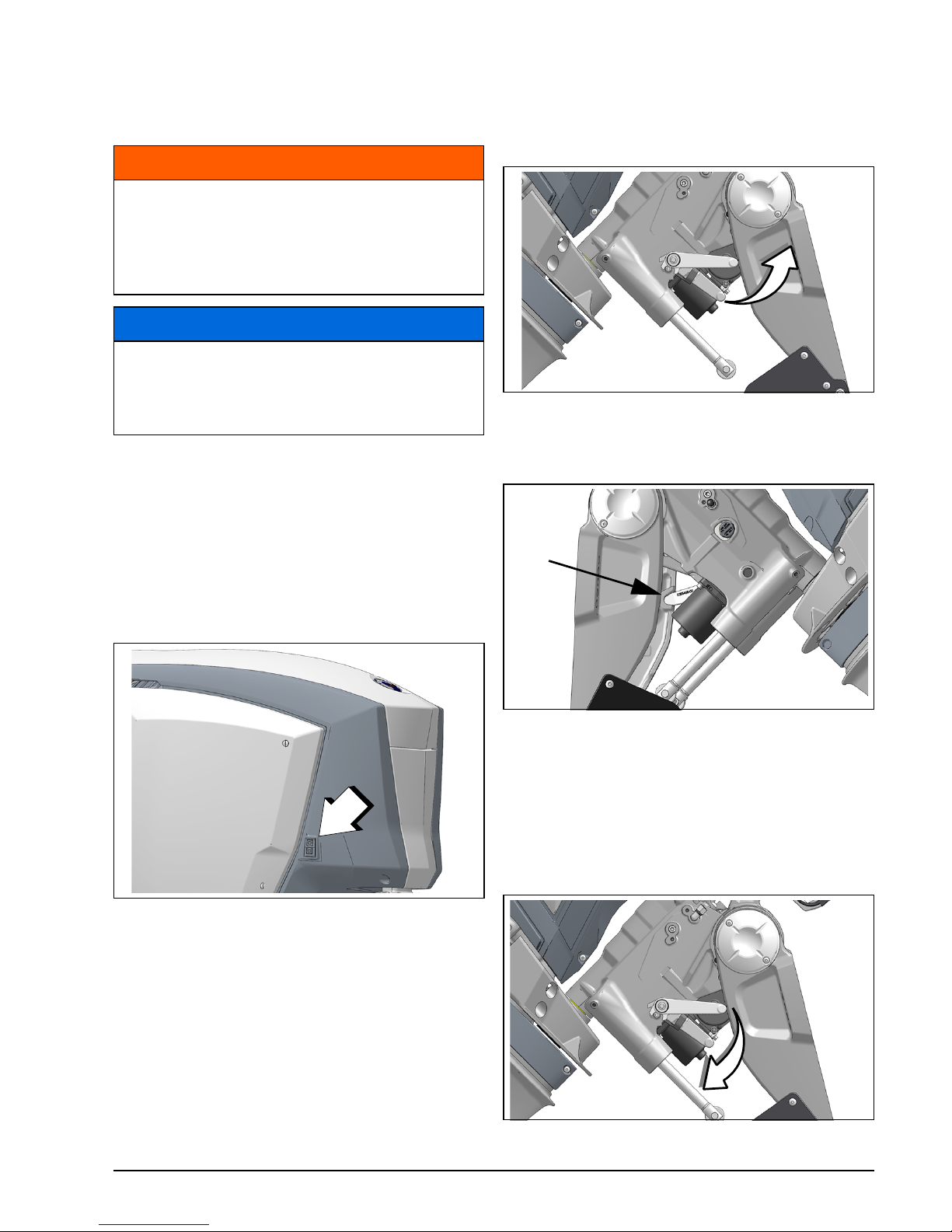
Trailering Lever
The outboard is designed to be trailered in a
tilted position using the trailering lever, or in a
vertical position.
To engage lever — Tilt the outboard fully us-
ing the trailering tilt switch on the starboard
engine cover, or the trim/tilt switch on the remote control.
Push the trailering lever up. A detent will hold
the lever in position.
Lower the outboard until the trailering lever
locks into place in the stern brackets.
Use the trailering lever if you intend to leave
the outboard tilted for a period of time.
To disengage lever — Tilt the outboard fully.
Return the trailering lever to its stowed position. Lower the outboard to its vertical position.
WARNING
Keep everyone clear of stern area when
raising or lowering the outboard. Personal injury or death can result from
contact with moving parts of the outboard.
NOTICE
When trailering your outboard, DO NOT
cover the engine with canvas—it will dull
the finish of the outboard’s engine covers.
1. Trailering tilt switch
009041A
1
009066
009083
009068
Page 38

34
Using Your Evinrude E-TEC G2 Outboard
Transporting / Storage
If the outboard is removed from the boat for
transportation or storage, you MUST:
• Seal the oil and fuel lines on the boat and on
the outboard to prevent leaks and prevent
contaminants from entering the oil or fuel
system.
• Install shipping brackets to prevent the outboard from turning.
• Cap steering fittings on the outboard and
hydraulic hoses to prevent leaks and prevent contaminants from entering the hydraulic system.
The engine is shipped from the factory without
color engine cover panels. A shipping cover is
used to protect the engine during shipment.
WARNING
A small amount of fuel may be released
when the fuel line is disconnected.
Gasoline is extremely flammable and
highly explosive under certain conditions. Do not allow disconnected fuel
hoses to leak fuel.
Use caution when working on the fuel
system. Wear safety glasses and work in
a well ventilated area. Extinguish all
smoking materials and make certain no
open flames or ignition sources exist.
Always wipe off any fuel spillage.
ENVIRONMENTAL NOTE
Dispose of oil or fuel contaminated towels in
an environmentally responsible manner, or
according to local regulations.
NOTICE
Do not install the shipping cover after
the engine cover panels are installed, the
decals or covers could be scratched.
Page 39
35
Pre-Ride Inspection
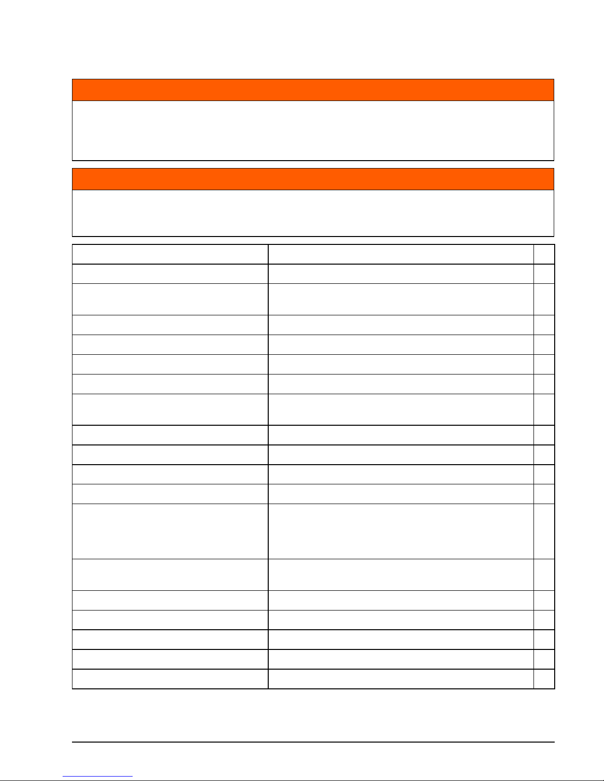
WARNING
Always perform a pre-ride inspection before operating the boat. Check the proper
operation of critical controls, safety features and mechanical components. Correct
any problems BEFORE leaving the dock. Make sure all safety equipment required by
local law is onboard.
WARNING
The engine(s) should be OFF and the tether cord must always be removed from the
engine cut-off switch before verifying any of the following. Only start the engine(s)
after all items have been checked and operate properly.
ITEM OPERATION
Hull Inspect.
Propeller
Inspect condition of propeller. Repair or replace
damaged propeller.
Cooling system Inspect water intake screens.
Safety equipment Ensure safety equipment is onboard.
Oil level Check. Refill as needed.
Bilge Drain. Ensure drain plug(s) are securely installed.
Battery
Check battery connections are clean, tight, and
insulated. Ensure battery/battery box are secure.
Fuel level Check. Refill as needed.
Navigation lights Check operation.
Steering system Check operation.
Boat systems (horn, pumps, radio) Check operation.
Engine cut–off switch/ tether cord
Inspect condition of tether cord. Attach to key
switch or engine cut–off switch (depending on
application). Test operation. Reattach tether cord
to switch.
Operator’s Guide
Confirm this Operator’s Guide is onboard and
readily accessible.
Key / Engine Start switches Test operation.
Displays & Gauges Self-test and warning horn, check operation
Shift and Throttle Check operation.
Trim System Check operation.
Cooling system Confirm operation (water pump indicator).
Page 40
36
Page 41

37
Maintenance
Page 42

38
Maintenance
Engine Emissions Installation Information
A repair shop or person of the owner's choosing may maintain, replace, or repair emission
control devices and systems. These instructions do not require components or service by BRP
or authorized Evinrude dealers. Although an authorized Evinrude dealer has the in-depth technical knowledge and tools to service Evinrude outboard engines, the emission-related warranty is not conditioned on the use of an authorized Evinrude dealer or any other establishment
with which BRP has a commercial relationship.
For emission-related warranty claims, BRP is limiting the diagnosis and repair of emission-related parts to authorized Evinrude dealers. For more information, please refer to the US EPA
EMISSION-RELATED WARRANTY contained herein. Proper maintenance is the owner's responsibility. A warranty claim may be denied if, among other things, the owner or operator
caused the problem through improper maintenance or use.
You must follow the instructions for fuel requirements in the FUEL REQUIREMENTS section
of this manual. Even if gasoline containing greater than ten volume percent ethanol is readily
available, the US EPA has issued a prohibition against the use of gasoline containing greater
than 10 vol% ethanol that applies to this engine. The use of gasoline containing greater than
10 vol% ethanol with this engine may harm the emission control system.
Manufacturer’s Responsibility
Beginning with 1999 model year outboards, manufacturers of marine engines must determine
the exhaust emission levels for each engine horsepower family and certify these outboards
with the United States of America Environmental Protection Agency (EPA). An emissions control information label, showing emission levels and engine specifications, must be placed on
each outboard at the time of manufacture.
Dealer’s Responsibility
When performing service on all 1999 and more recent Evinrude outboards that carry an emissions control information label, adjustments must be kept within published factory specifications.
Replacement or repair of any emission related component must be executed in a manner that
maintains emission levels within the prescribed certification standards.
Dealers are not to modify the outboard in any manner that would alter the horsepower or allow
emission levels to exceed their predetermined factory specifications.
Exceptions include manufacturer’s prescribed changes, such as altitude adjustments, for example.
Owner Responsibility
The owner/operator is required to have engine maintenance performed to maintain emission
levels within prescribed certification standards.
The owner/operator is not to, and should not allow anyone to, modify the engine in any manner
that would alter the horsepower or allow emissions levels to exceed their predetermined factory specifications.
Page 43

39
ENGINE EMISSIONS INSTALLATION INFORMATION
Tampering with the fuel system to change horsepower or modify emission levels beyond factory settings or specifications will void the product warranty.
EPA Emission Regulations
All new 1999 and more recent Evinrude outboards manufactured by BRP are certified to the
EPA as conforming to the requirements of the regulations for the control of air pollution from
new watercraft marine spark ignition engines. This certification is contingent on certain adjustments being set to factory standards. For this reason, the factory procedure for servicing the
product must be strictly followed and, whenever practicable, returned to the original intent of
the design. The responsibilities listed above are general and in no way a complete listing of
the rules and regulations pertaining to the EPA requirements on exhaust emissions for marine
products. For more detailed information on this subject, you may contact the following locations:
U.S. Environmental Protection Agency
Office of Transportation and Air Quality
1200 Pennsylvania Ave. NW
Mail Code 6403J
Washington D.C. 20460
EPA Internet Web Site:
www.epa.gov/otaq
Page 44
40
Maintenance
Maintenance & Inspection Schedule
Routine inspection and maintenance is necessary to ensure outboard life. The following chart
provides guidelines for inspection and maintenance. The 500 hour/5 year service should be
performed by an authorized Dealer, repair shop, or person of your own choosing.
IMPORTANT: Adjust the maintenance schedule for operating and environmental conditions.
Outboards used in rental, commercial, or other high hour applications require more frequent
inspections and maintenance.
(1) Whichever comes first. Certain conditions may require more frequent inspection and maintenance.
(2) Annually in salt water applications – Refer to Service on page 41.
(3) Emission-related component. Refer to Owner Responsibility on page 38, Product Warranty Information
on page 59 and, if applicable, California Emission Control Warranty Statement on page 68.
Engine Care Products
The engine care products listed in the table below are referenced in this guide, and are recommended for use with Evinrude E-TEC G2 outboards.
Description
Dealer Maintenance Every 500 Hours or 5 Years
(1)
Customer Inspections Every 100 Hours or Annually
(1)
Engine Care Product
Action
Anodes (corrosion protection) Check condition
(1), (2)
Back pressure probe Replace
Covers
Wash and wax, repair scratches
Fluid levels (steering and trim)
Inspect level
Fuel filters
Replace
Gearcase lubricant
Inspect level, See “Gearcase Lubricant Level”
on page 42.
Gearcase lubricant
Replace
A
Grease fittings
Lubricate
B
Oil Filter
(optional remote oil tank only)
Replace
Propeller shaft splines
Inspect and lubricate
B
Service codes
Access EMM, check for and resolve any codes
Spark plugs
Replace
(3)
Thermostat
Inspect
(3)
Water pump
Replace
Product Use
A. HPF Pro Gearcase Lubricant Gearcase
B. Triple-Guard Grease Grease fittings, propeller shaft
– Power Trim/Tilt Fluid, P/N 767969 Power Trim and Tilt System
– SeaStar Steering Fluid, P/N 770891 Hydraulic Steering System
– Evinrude 2+4 Fuel Conditioner Protect fuel system and condition fuel
– Anti–Corrosion Spray Protect metal parts from corrosion
Page 45

41
Service
Anodes
Your outboard is equipped with one or more
sacrificial anodes that protect it from galvanic
corrosion. Disintegration of the anode is normal and indicates it is working. Check each
anode periodically. Replace anodes smaller
than 2/3 their original size. See your Dealer
for replacements.
Galvanic corrosion destroys underwater metal parts and can occur in fresh or salt water;
however, salt, brackish, and polluted waters
will accelerate corrosion.
Metal-based anti-fouling paint on the boat or
outboard and the use of improperly installed
shore power in the area of your moored boat
will also accelerate corrosion.
Flushing
Flush the outboard with fresh water following
use in brackish, or polluted water to minimize
the accumulation of scale and silt deposits in
cooling system passages. The outboard can
be flushed on the trailer or at dockside. Trim
the outboard to the fully down position in a
well ventilated area.
It is not necessary to run the engine when
flushing. IF you decide to run the engine observe the following additional steps:
• Remove the propeller.
• RUN AT IDLE SPEED only.
• Reinstall the propeller. See Propeller on
page 54.
Anti-corrosion anodes 009069
Anti-corrosion anode 009070
NOTICE
NEVER paint the anode, its fasteners, or
its mounting surface. Painting will
reduce its corrosion protection.
NOTICE
IMPORTANT: Trim the outboard to the
vertical (down) position to flush the
engine.
Flushing the engine with the outboard
tilted can allow water to enter the cylinders, resulting in engine damage.
When flushing is complete, store the outboard in the recommended down position.
If the outboard must be stored in a tilted
position, make SURE the cooling system
is drained completely BEFORE tilting.
Never place the gearcase higher than the
powerhead. Any water remaining in the
exhaust passages can run into the cylinders and cause serious damage.
Page 46
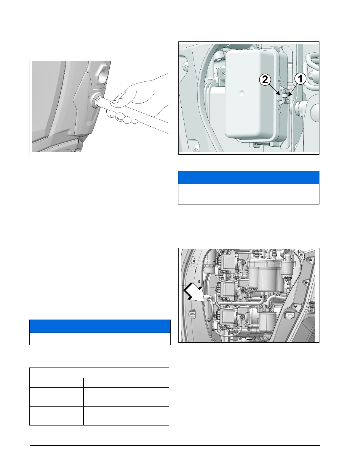
42
Maintenance
Lower Engine Cover Flushing Port
1) Place the outboard in an area with good
drainage.
2) Connect a garden hose to the flushing port.
3) Trim the outboard to the vertical (down) po-
sition.
4) Turn on the water. Keep the water pres-
sure between 20 and 40 psi (140 to
300kPa).
5) After flushing, leave the outboard in the
vertical position long enough to completely
drain the powerhead.
Fuses
A blown fuse could prevent the engine from
starting.
Repeated fuse failures indicate a potentially
serious problem. Do not replace it with higher
rated fuse.
Fuse Replacement
Your outboard uses the following Mini-Fuses.
See your Dealer for replacement fuses.
Remove port engine cover. Remove cover
from fuse box. Replace failed fuse.
Gearcase Lubricant Level
Remove starboard engine cover. Inspect the
lubricant level in the oil reservoir.
009071
NOTICE
Use only fuses of the same rating.
Fuses
Fuse Rating Replacement Fuse P/N
3 3011805
5 514764
10 514766
30 3011729
Fuse Box 009074
NOTICE
Failure to install cover securely may
cause electrical problems.
1. Lubricant reservoir
009140
1
Page 47
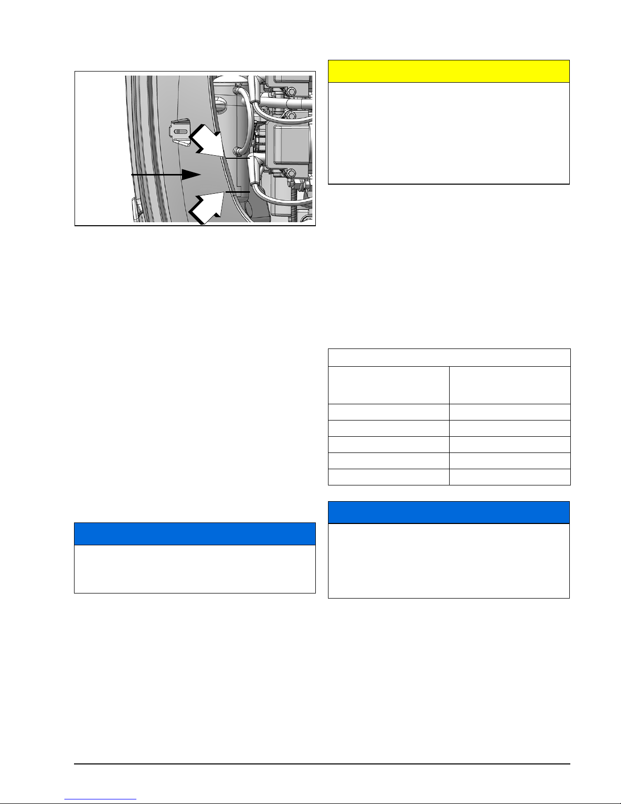
43
SERVICE
Lubricant level should be between the marks
as shown.
Hull Finish
The condition of your boat’s bottom affects
performance. Marine growth or bottom painting may reduce speed and fuel efficiency.
For maximum performance, keep the boat’s
running surface clean by rinsing it with fresh
water and wiping it dry. Apply Evinrude anticorrosion spray to any surface subject to corrosion, but avoid the anti-corrosion anode(s).
Outboard External Finish
Periodically, wash the entire boat and outboard with soapy water and apply a coat of
automotive wax. Leave the engine covers in
place when washing the outboard.
Scratch Repair
Surface scratches on the engine covers can
be repaired or painted.
IMPORTANT: Your Dealer has the professional materials or matching paint colors to
properly repair scratches. See your Dealer to
repair any deep scratches or gouges.
Spark Plugs
Incorrect spark plug maintenance can lead to
engine damage.
Marine Engine Duty Cycles
The International Council of Marine Industry
Associations (ICOMIA) Standard No. 36-88
specifies a marine engine duty cycle based on
documented studies. A duty cycle is a profile
of engine running and usage. This duty cycle
is used to determine average spark plug longevity and maintenance requirements.
Submerged Outboard
If your outboard has been under water, have
it serviced immediately upon recovery.
After submersion, all boat and engine electrical, fuel, and oiling systems must be inspected for signs of water intrusion. See the
Service Note on page 48.
Lubricant Level
1. Maximum
2. Minimum
009141
NOTICE
If needed, use Evinrude Marine Cleaner
to clean plastic covers or panels. Do
NOT use solvents such as acetone.
{
1.5 in.
(38 mm)
1
2
CAUTION
The ignition system presents a serious
shock hazard. Use caution to avoid
injury from shock or injury resulting
from your reaction to shock. Do not handle primary or secondary ignition components while the engine is cranking or
running.
ICOMIA Marine Engine Duty Cycle
Engine Speed as
Percentage of Rated
Speed (RPM)
Time at Specified RPM
(Percentage of total
engine running time)
IDLE 40%
40% 25%
60% 15%
80% 14%
100% 6%
NOTICE
Some running profiles and conditions
can lead to spark plug wear sooner than
expected. Depending on your specific
usage, the spark plug maintenance
schedule may require adjustment.
Page 48
44
Maintenance
Storage
Protect against natural environmental conditions that can be damaging to an outboard.
Your warranty does not cover engine failure
caused by these conditions.
Stabilize the fuel supply. Fuel remaining in
your fuel tank can oxidize, resulting in loss of
octane and fuel system deposits.
Use Evinrude 2+4 Fuel Conditioner to prevent
gum and varnish deposits from forming in fuel
system components.
If the outboard is removed from the boat for
transportation or storage, you MUST:
• Seal the oil and fuel lines on the boat and on
the outboard to prevent leaks and prevent
contaminants from entering the oil or fuel
system.
• Install shipping brackets to prevent the outboard from turning.
• Cap steering fightings on the outboard and
hydraulic hoses to prevent leaks and prevent contaminants from entering the hydraulic system.
Short-Term Storage
If you must tilt the outboard to remove it from
the water, lower it and allow the cooling system to drain completely as soon as you clear
the launch area. Between uses, store your
outboard in a vertical position.
Long-Term Storage (Winterization)
Winterization prepares your outboard for
long-term off-season storage. During winterization, the engine is “fogged” with extra oil to
coat internal engine components.
Winterization requires a specific process of
steps.
Note: The Evinrude ICON touch digital dis-
play provides a one-touch winterization. See
the ICON Touch User’s Guide.
Closely follow the applicable winterization
procedure for your outboard:
• Remote control
• Remote control with foot throttle
You can confirm your outboard enters winter-
ization mode when the engine runs at fast idle
and:
• The ICON or I-Command gauges display a
winterization message (if equipped).
• The SystemCheck gauge lights flash (if
equipped).
Preparation
Your outboard can be winterized in the water.
If winterizing in water, make sure the water
intake screens are completely submerged.
1) Stabilize the engine’s fuel supply. Add 2+4
Fuel Conditioner following instructions on
container. Fill fuel tank.
2) If winterizing on a trailer, remove the pro-
peller. Attach a garden hose to flushing
WARNING
DO NOT run the engine indoors or without adequate ventilation or permit
exhaust fumes to accumulate in confined
areas. Engine exhaust contains carbon
monoxide which, if inhaled, can cause
serious brain damage or death.
NOTICE
Temperature and humidity changes
during storage period can cause corrosion of internal engine components.
WARNING
Prevent injury from moving engine components. Before starting the outboard:
• Shift it to NEUTRAL.
• Keep hands, clothes, and hair clear of
powerhead.
If on a trailer, remove the propeller.
WARNING
If winterizing on a trailer, the propeller
must be removed before performing procedure. Failure to remove propeller can
cause personal injury or death.
Page 49
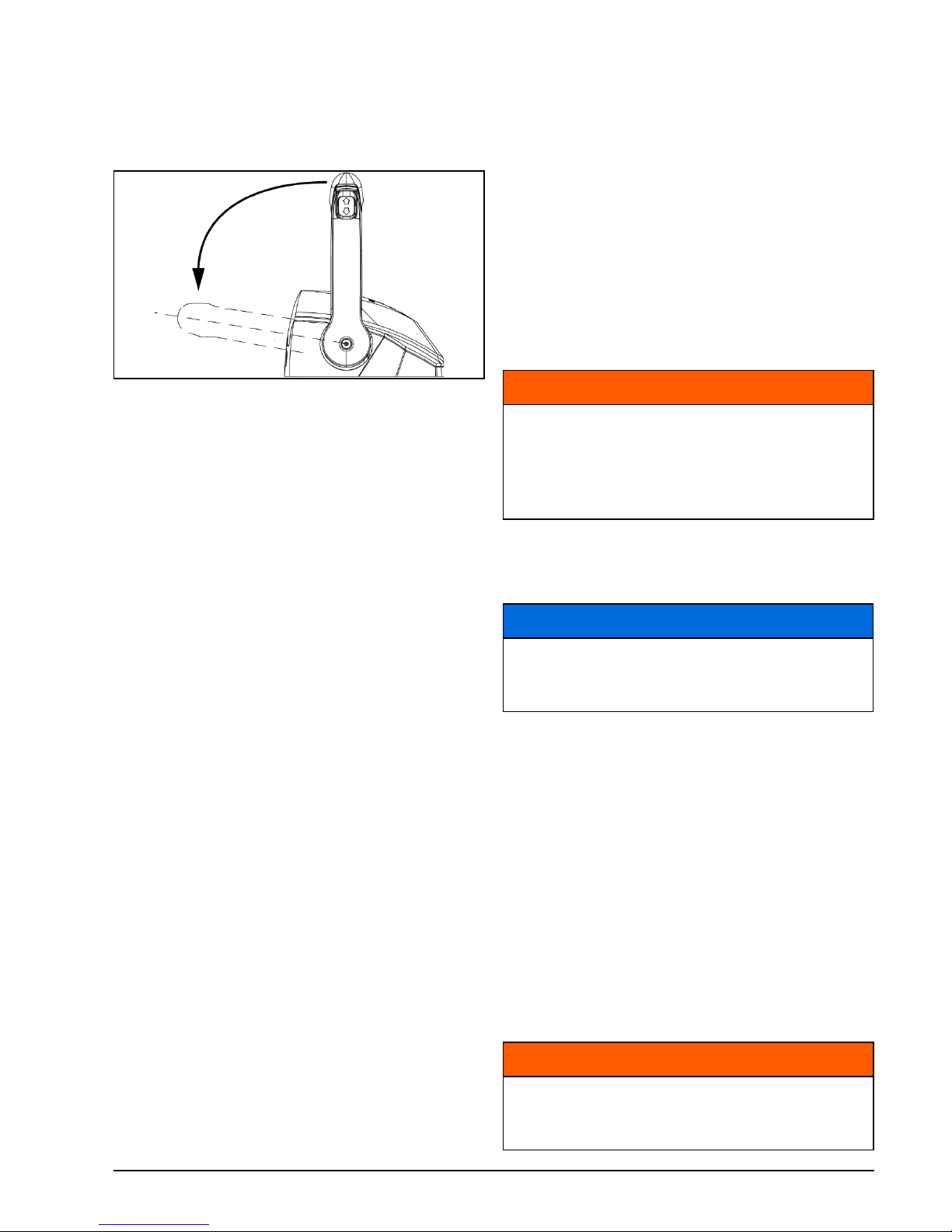
45
STORAGE
port and turn on the water. Refer to Flushing on page 41.
3) Turn the key switch to the OFF position.
4) Move the lever(s) to the FORWARD wide
open throttle position.
5) Turn the key switch to ON and wait a minimum of three seconds.
6) Attempt to start the outboard three times
within three seconds (the starter will not
engage or crank the outboard).
7) Move the lever to NEUTRAL and start the
outboard(s).
8) Run the outboards at idle for a minimum of
three seconds.
9) With the outboard(s) running, attempt to
start the outboard three times within three
seconds (the starter will not engage or
crank the outboard).
10)The remote control will send the winterization message to each outboard. Only running outboard(s) will be winterized.
11)The outboard(s) will automatically shut off
when the process is complete.
During the winterization process, the remote
control will ignore all throttle, gear, and switch
operations. The control WILL acknowledge
Key OFF or Emergency Stop commands.
Trim the outboard to the fully down position to
store. If the outboard must be stored in a tilted
position, make SURE the cooling system is
drained completely BEFORE tilting.
Pre-Season Check
Remove your outboard from storage and prepare it for a season of reliable service by performing a general check and a few preventive
maintenance procedures.
Check for loosened or removed hardware.
Replace damaged or missing parts with Evin-
rude Genuine Parts or equivalent. Check the
gearcase for leakage. If leakage is evident,
the gearcase seals should be replaced. See
the Service Note on page 48.
IMPORTANT: Gearcase lubricant is thick
and clear. Do not confuse this with engine oil,
which may normally appear on the skeg after
performing the long-term storage procedure.
Anti-corrosion anodes — Check condition.
See Anodes on page 41.
Battery — Charge. See Battery on page 52.
Review your outboard’s warning system selftest routine. During start-up, make sure the
warning system self-tests properly.
Following Engine Starting on page 21, start
the outboard. If the outboard was winterized,
it will emit a puff of smoke on the first start of
the season.
Let engine idle while you:
Observe running quality. If poor, refer to
Troubleshooting on page 46.
Confirm water pump operation. Water must
flow from the water pump indicator in a steady
stream. If it does not, shut off the outboard
and investigate.
Stop the outboard and check the fuel system
for leaks.
Binnacle Mount Control (shown) 009076
WARNING
Do not use a booster battery and jumper
cables to start the outboard. Gasoline
fumes can cause explosion and fire,
resulting in property damage, personal
injury or death.
NOTICE
Do not run your outboard—even for a
brief start-up—without supplying water
to it.
WARNING
Failure to check for fuel leakage could
allow a leak to go undetected, resulting
in fire or explosion.
Page 50

46
Maintenance
Troubleshooting
SYMPTOM POSSIBLE CAUSE
Starter motor will not
operate
• Shift handle not in NEUTRAL.
• Fuse blown.
• Battery switch is in OFF position.
• Battery is dead.
• Flashing “NEUTRAL” LED indicator on remote control, refer to
Emergency Start Procedure on page 46
Engine will not start • Not following starting instructions. Refer to Engine Starting /
Stopping on page 19.
• Fuel system not primed after running out of fuel. Refer to
Operation on page 19.
• Fuel tank empty.
• Fuel hose kinked.
• Fuel system contaminated with water or dirt.
• Fuel filter obstructed.
• Spark plugs incorrect. Refer to Service on page 41.
• Spark plugs improperly gapped, carboned, burned, or wet.
• Flashing “Check Engine” or “Chk Eng” indicator, refer to Engine
Monitoring on page 30.
Run Quality /
Engine will not idle
properly
• Debris on propeller.
• Spark plugs damaged or incorrect. Refer to Service on page 41.
• Fuel system contaminated with water or dirt.
Run Quality /
Engine loses power
• S.A.F.E. protection mode activated. Review warning system
information elsewhere in this chart. Also refer to Engine
Monitoring on page 30.
• Water intakes obstructed and cooling system not operating
correctly. Refer to Special Operating Conditions on page 32.
• Spark plugs damaged or incorrect. Refer to Service on page 41.
• Fuel filter obstructed.
• Fuel system contaminated with water or dirt.
• Oiling system malfunction.
Engine runs, but
makes little or no
progress
• Throttle needs to be reset, refer to Operation on page 19.
• Propeller hub loose, slipping.
• Propeller blades bent or missing.
• Propeller fouled with debris.
Warning system
activates the TEMP
warning
S.A.F.E. protection mode activated with a continuous indicator —
The EMM has identified an overheating condition.
• Check the water pump indicator for a steady stream of water.
Shut OFF the engine.
• Clear the water intake screens of any debris. If the overheat condition still exists, the engine will operate in “get home” mode. Return to harbor immediately.
•See S.A.F.E. Reset on page 47.
S.A.F.E. protection mode activated with a flashing indicator —
The EMM has identified a damaging overheating condition. The
engine will not operate.
• Allow the engine to cool for 20 minutes and return to harbor.
•See S.A.F.E. Reset on page 47.
•See the Service Note on page 48.
Page 51

47
TROUBLESHOOTING
S.A.F.E. Reset
In the event of an engine overheat, it may be
possible to reset the S.A.F.E. system and restore normal operation:
• The engine must be shut off and the cooling
temperature restored.
IF the S.A.F.E. mode activates and water
pressure becomes intermittent or stops, reduce speed to idle and:
1) Shift to NEUTRAL.
2) SHUT OFF the engine.
3) Tilt the outboard up.
4) Clean the water intake screens of any
blockage.
5) Clean the water pump indicator of any
blockage.
6) Lower the outboard.
7) Restart the engine and run at idle.
IF cleaning the screens and indicator does
not restore the water pump indicator’s steady
discharge, the engine will operate only in
S.A.F.E. mode. Return to harbor immediately.
See the Service Note on page 48.
IF cleaning the screens and indicator does re-
store the water pump indicator’s steady discharge, you might have to run for two minutes
in NEUTRAL to allow the engine to cool and
the warning indicator to turn OFF.
IMPORTANT: If cooling is not restored, the
EMM will identify a progressive overheating
condition and shut off the engine. The
“TEMP” warning will flash. The engine will not
restart until the engine is allowed to cool.
(Continued on next page)
Warning system
activates the CHECK
ENGINE warning
S.A.F.E. protection mode activated with a continuous indicator —
The EMM has identified a problem with the outboard.
• Seek assistance and/or return to harbor.
• See the Service Note on page 48.
A continuous indicator without S.A.F.E. mode —
The EMM has identified a problem that should be addressed as
soon as practical to avoid operational difficulties. See the Service
Note on page 48.
Shut-down mode activated with a flashing indicator —
The EMM has identified an abnormal operating condition related to
the fuel system.
• The engine will shut OFF and cannot be restarted.
• Seek assistance and/or return to harbor.
• See the Service Note on page 48.
S.A.F.E. protection mode activated with a continuous indicator,
outboard reduces speed to idle and shifts into NEUTRAL. Remote
control LED indicators flashing rapidly. The digital display
identifies codes 114 and 115, loss of network communication —
The EMM has identified a problem with the digital networks.
• Reset networks. Turn the key switch OFF. Then restart the engine(s).
• Seek assistance and/or return to harbor.
• See the Service Note on page 48.
Steering is not smooth
or feels “bumpy”
• Air in steering system
• Hydraulic steering fluid low
• Hydraulic hose kinked or restricted.
•See the Service Note on page 48.
Steering effort is high • Air in steering system.
• Hydraulic hose kinked or restricted.
•See the Service Note on page 48.
SYMPTOM POSSIBLE CAUSE
Page 52
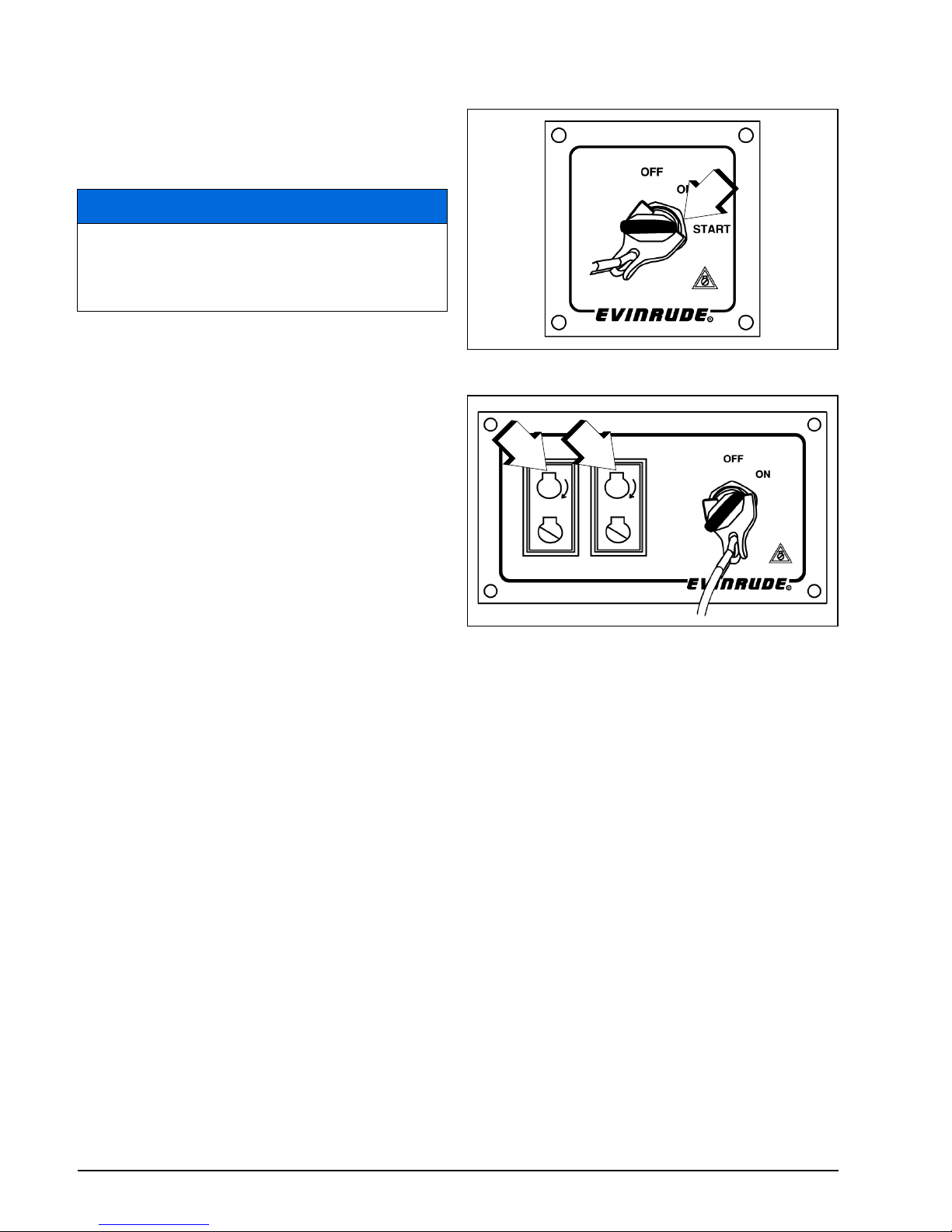
48
Maintenance
After any overheat causing engine shutdown,
The following items should be inspected:
• Inspection of the water pump for excessive
wear or damage.
• Inspection of the thermostats.
• See the Service Note on page 48.
Service Note
Seek service from an authorized Evinrude
dealer, repair shop, or person of your own
choosing for maintenance, repair, or replacement. Please refer to the US EPA EMISSIONRELATED WARRANTY contained herein for
information about warranty claims.
Emergency Start Procedure
IMPORTANT: Evinrude E-TEC G2 models
use a dedicated remote control network for all
remote control-related functions.
In the event network communication between
the remote control and the engine EMM is disabled, back-up remote control function is provided using the NMEA 2000 network.
Start the engine using the following procedure:
1) Turn the key switch to the ON position.
Note: The NEUTRAL LED indicator on the remote control will flash rapidly, and digital displays may show a network communication
service code or warning.
2) Use the trim switch on the starboard side of
the engine to momentarily activate the trim
system.
3) Turn the key switch to the START position
or press the START button within 10 seconds of activating the trim system.
In multiple engine applications, repeat this
procedure for each engine.
NOTICE
Although the S.A.F.E. mode can help pre-
vent engine damage, it does not guarantee you can run your engine indefinitely
without engine damage.
1. Key switch START position
009048
1. Start buttons
009158
1
1
1
Page 53

49
Product Information
Page 54
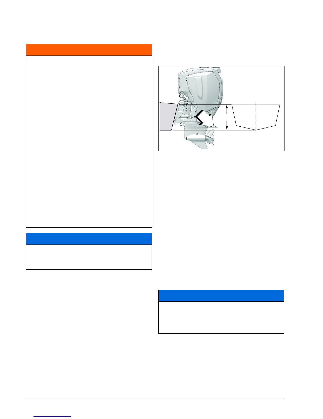
50
Product Information
Installation
Transom Height
Make sure the transom height matches the
length of the outboard to be installed.
• A 19 to 21 in. (48.3 to 53.3 cm) transom
height uses a 20 in. (50.8 cm) shaft outboard.
• The shaft length of the outboard being installed should come close to matching the
transom height of the boat.
•Refer to Specifications on page 56 for
transom height.
Determine transom height by measuring from
the top edge of the transom, along the centerline.
Boat performance depends on outboard
mounting height.
Generally, the anti-ventilation plate of the
gearcase should align approximately 1 in. (25
mm) above the bottom of the hull.
Test outboard and boat performance at different heights until the best performance is
achieved.
IMPORTANT: Be sure that outboard water
pressure is not adversely affected by the
mounting height of the outboard.
Outboard Shipping Cover
WARNING
Your outboard must not exceed the maximum horsepower indicated on the
boat’s capacity plate. Such overpowering can cause loss of control. Contact
your Dealer or the boat’s manufacturer if
your boat lacks a capacity plate.
Incorrectly matched boat and outboard
transom heights can cause boat instability and loss of control. Refer to Transom
Height.
Prevent lateral movement and possible
outboard loss by using the mounting
hardware supplied or hardware of sufficient size, strength, and quality. Refer to
Installing the Outboard on page 51.
A mounting surface that is damaged or
too thin to support your outboard while
underway might fail during operation,
causing a loss of control. Be sure the
boat’s transom or mounting bracket is
structurally sound and between 1 3/4 in.
(45 mm) and 2 3/4 in. (70 mm) in thickness.
NOTICE
Use an appropriate hoist to lift the
engine. Refer to Specifications on page
56 for engine weight.
1. Centerline
2. Antiventilation plate
3. Transom Height
0009077
NOTICE
Remove the outboard shipping cover
BEFORE running the outboard. The shipping cover does NOT provide adequate
air flow to run the engine.
3
1
2
Page 55
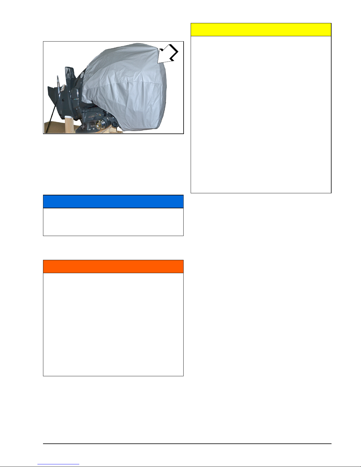
51
INSTALLATION
Remove shipping carton. Remove the outboard shipping cover.
If the engine cover panel kit is not available,
the shipping cover can be reinstalled to store
the outboard short term.
Discard the outboard shipping cover after the
engine cover panels are installed.
Installing the Outboard
IMPORTANT: Follow all directions carefully.
The outboard’s warranty will not cover product damage or failure that results from incorrect outboard installation.
Boat-Mounted Fuel Filters
Boat-mounted fuel filters and water-separating fuel filter assemblies must meet the following requirements:
• Fuel flow – 0.4 in. Hg maximum pressure
drop at 20 gph (76 l/hr) flow.
• Filter area – 150 in.2 (1290 cm2) of filter
area.
The filter must be mounted to a rigid surface
above the full level of the fuel tank and accessible for servicing.
Fuel Filter Assembly, P/N 174176, meets all
requirements for a water-separating fuel filter.
If equipped, replace the boat-mounted fuel filter annually.
1. Shipping cover
009150
NOTICE
Do not install the shipping cover after
the engine cover panels are installed, the
decals or covers could be scratched.
WARNING
The outboard must be correctly installed.
Failure to correctly install the outboard
could result in serious injury, death or
property damage.
BRP recommends your Dealer install
your outboard to ensure proper installation, set-up and satisfactory performance.
If you install the outboard yourself, follow the instructions in the Installation
and Predelivery Guide, available from
your Dealer.
1
CAUTION
Improperly supporting an engine during
lifting can result in personal injury or
damage to the engine, boat or other
property.
Verify the hoist has the correct lifting
capacity for the engine weight.
An Engine Lift Fixture, P/N 357667, is
REQUIRED to safely lift the engine. Do
NOT substitute any other lifting device.
To avoid personal injury or damage to
engine, boat or property, always install
the fixture completely into the flywheel.
To properly install the fixture, carefully
thread the fixture into the flywheel at
least 6 complete turns. Do NOT crossthread or over-torque the fixture.
Refer to the Installation & Predelivery
Guide.
Page 56
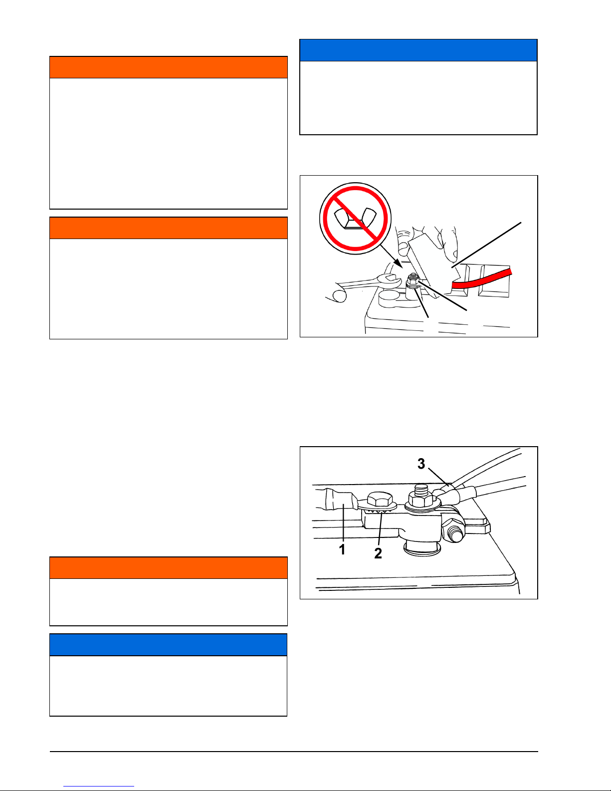
52
Product Information
Battery
Requirements
• 12-volt, heavy-duty, designated for "marine"
use;
• Vented/refillable or maintenance-free; and
• Rated according to the minimum requirements in Specifications on page 56.
Deep-cycle batteries are suitable IF they
meet or exceed the minimum CCA requirements.
Ask your Dealer about your outboard’s requirements before installing longer battery cables or a battery switch.
Installation
Marine Battery Posts — install each main ca-
ble on the post with a star washer below it.
Battery Terminal Adapter Kit, P/N 385407 —
install the main cable on the adapter with a
star washer below it. Install wires from accessories on the threaded portion of the post.
Automotive Type Battery Posts — Use Bat-
tery Terminal Adapter Kit, P/N 385407. Place
a star washer on the adapter first, then the
WARNING
Battery electrolyte is acidic — handle
with care. If electrolyte contacts any part
of the body, immediately flush with water
and seek medical attention.
Do not use a booster battery and jumper
cables to start the outboard. Gasoline
fumes can cause explosion and fire,
resulting in property damage, personal
injury or death.
WARNING
Keep battery connections clean, tight,
and insulated to prevent their shorting or
arcing and causing an explosion. If the
battery mounting system does not cover
the connections, install covers. Check
often to see that connections stay clean
and tight.
WARNING
Read and understand the safety information supplied with your battery BEFORE
installation.
NOTICE
Be sure all components are clean and
free of corrosion. Connect RED (+) cable
to the positive (+) post first. Connect
BLACK (–) cable to negative (–) post last.
NOTICE
DO NOT use wing nuts on battery connections even if they came with the battery. Wing nuts can loosen and cause
errant warning signals or electrical system damage.
1. Main cable
2. Starwasher
3. Terminal insulator
009166
1. Main cable
2. Starwasher
3. Accessory wires
DR6495
2
1
3
Page 57
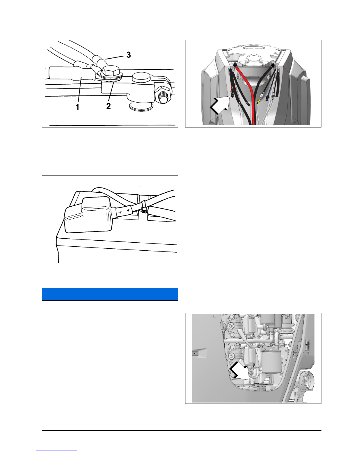
53
INSTALLATION
main cable. Install wires from the accessories
on the main cable.
Tighten all connections securely and coat the
installation with Triple-Guard grease.
Service
Before servicing the battery or the outboard,
remove both battery cables from the battery,
battery negative (–) cable first. Keep metal
objects from contacting either battery post.
Accessory Battery Connection
An optional accessory battery charge kit is
available to allow the charging system to
charge the cranking and accessory batteries
at the same time. See your Dealer to order
and install this kit (P/N 5009079).
IMPORTANT: The accessory battery connection must only be used to charge a single 12volt battery or two 12-volt batteries wired in
parallel. The accessory connection must not
be used to charge either battery in a 24-volt
system.
Water Pressure
An optional water pressure gauge is recommended to monitor cooling system pressures.
Noticing changes in water pressure can help
prevent engine overheating. The water pressure gauge must be connected at the correct
point to ensure the most accurate pressure
readings.
Follow the installation instructions included
with the water pressure gauge.
Note: Use of Evinrude Diagnostics software is
REQUIRED to activate this feature. See your
authorized Evinrude dealer for this service.
1. Main cable
2. Starwasher
3. Accessory wires
DR6496
DR5104
NOTICE
Service electrical components only while
the outboard is NOT running. Be careful
when identifying positive and negative
battery cables and posts.
1. Accessory battery connector
009118
1. Water pressure port (starboard)
009078
1
1
Page 58
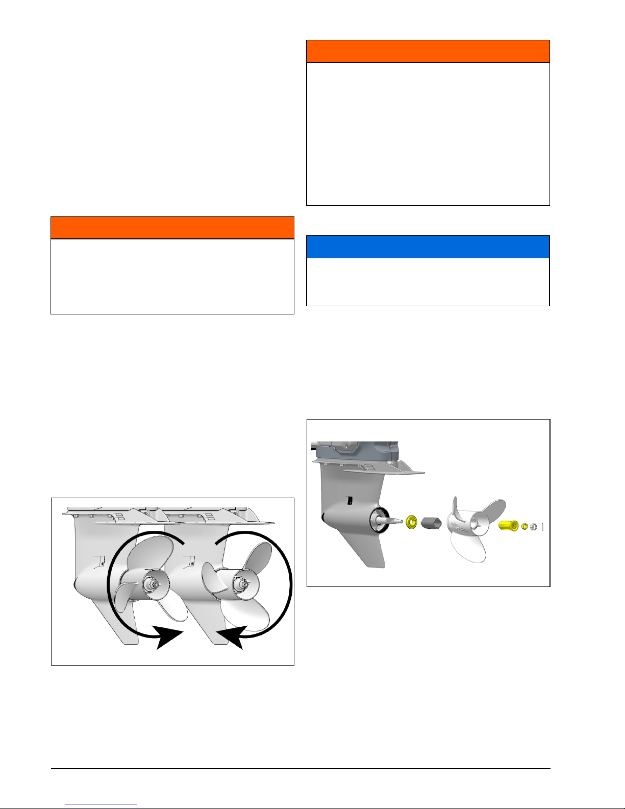
54
Product Information
Propeller
Propeller Selection
To select the correct propeller for your boating
application, your boat and outboard MUST be
water tested. See your Dealer for assistance.
IMPORTANT: The correct propeller for your
boat, under normal load conditions, will allow
the engine to run near the midpoint of the
RPM operating range at full throttle. Refer to
Specifications on page 56.
Standard vs. Counter Rotation
Right-hand propellers are considered standard rotation propellers. When propelling a
boat forward, the propeller rotates in a righthand (clockwise) direction as viewed from the
rear.
Left-hand propellers are considered counter
rotation propellers. When propelling a boat
forward, the propeller rotates in a left-hand
(counterclockwise) direction as viewed from
the rear.
Installation
Slide thrust washer onto shaft with shoulder
facing aft.
Slide propeller onto shaft, engaging the
splines and seating it on the thrust bushing.
Slide spacer onto the shaft and engage the
propeller shaft splines.
Wedge a block of wood between the propeller
blade and the anti-ventilation plate.
Install propeller nut and tighten to a torque of
70 to 80 ft. lbs. (95 to 109 N·m). Install keeper
on propeller nut, align keeper slots and cotter
pin hole.
IMPORTANT: If cotter pin holes in the propeller nut and propeller shaft are not aligned,
WARNING
When servicing the propeller, always
shift the outboard to NEUTRAL position,
turn the key switch OFF and remove the
key, so the outboard cannot be started
accidentally.
009079
WARNING
In multiple outboard installations, check
to make sure correct propellers are
installed on each outboard before
aggressively operating your boat. Shift
each engine individually into FORWARD
or REVERSE, at idle speed only. If the
boat moves opposite the direction indicated by the remote control handle, the
wrong propeller has been installed on
the outboard being checked.
NOTICE
Apply Triple-Guard grease to the entire
propeller shaft before installing the propeller.
Propeller Hardware – Typical 009080
Page 59
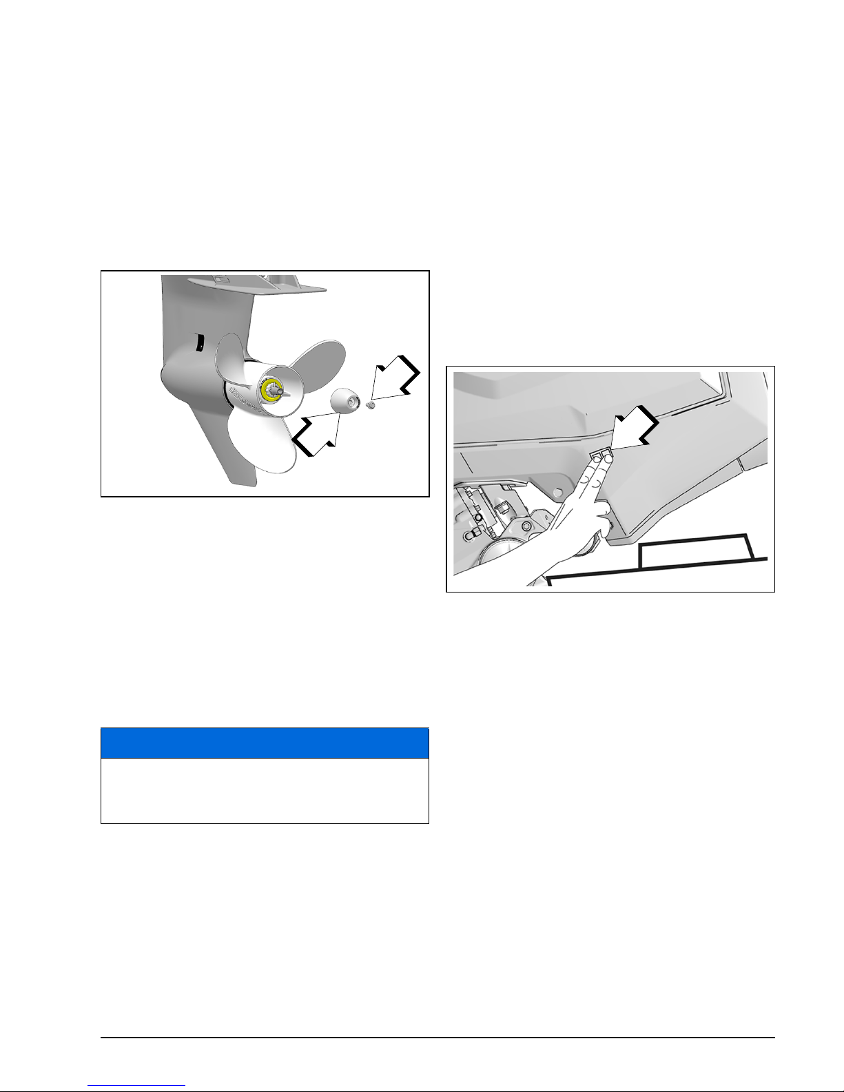
55
INSTALLATION
tighten the nut until they are in line. Do not
loosen.
Install new cotter pin and bend ends to secure.
Remove block of wood. Make sure engine is
in NEUTRAL; give propeller a spin. It must
turn freely.
Install the anode and screw on the propeller
shaft. Tighten the screw to 177 to 204 in. lbs.
(20 to 23 N·m).
Repair
If your propeller hits a solid object, the impact
is partially absorbed by the bushing in the hub
to help prevent damage to the outboard. A
strong impact can damage the hub and propeller blades. Damage to blades can cause
unusual and excessive vibration. Damage to
the hub can cause excessive engine RPM
with little forward movement.
Keep your propeller in good condition. Use a
file to smooth slight damage to blade edges.
See your Dealer for repair of serious damage.
Adjustments
Tilt Limit
Set the tilt limit if your outboard contacts the
boat’s motor well while tilting.
Manual Method
IMPORTANT: You MUST use the trim switch
on the starboard engine cover to set the tilt
limit with this method.
Tilt the engine up to the desired maximum tilt
position.
Then, simultaneously press both the up and
down trim buttons and hold for at least three
seconds.
To change or clear this setting, tilt the engine
to the full down position.
Then, simultaneously press both the up and
down trim buttons and hold for at least three
seconds.
Diagnostic Software Method
Your Dealer must use Evinrude Diagnostic
software to limit maximum tilt-up.
Check your adjustment — tilt the outboard fully and adjust further, if necessary. Check after
each adjustment.
1. Anode
2. Screw
009081
NOTICE
Avoid or limit operation using a damaged propeller. You may want to carry a
spare propeller.
2
1
1. Trim switch
009142
1
Page 60
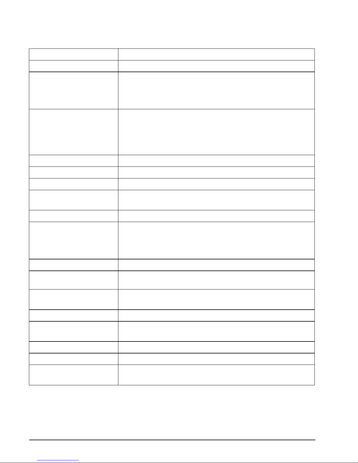
56
Specifications
200, 225, 250, 300 HP (3.4 Liter, 74° V6) Models
Displacement 210 cu. in. (3441 cc)
Engine Type 74° V, 6 Cylinder, Two-Cycle, E-TEC
Full Throttle Operating
Range
200 HP – 5400 to 6000 RPM
225 HP – 5400 to 6000 RPM
250 HP – 5400 to 6000 RPM
300 HP – 5400 to 6000 RPM
Power
(1)
200 HP – 200 HP (147 kw) @ 5500 RPM
225 HP – 225 HP (166 kw) @ 5500 RPM
250 HP – 250 HP (184 kw) @ 5500RPM
250 H.O. – 250 HP (184 kw) @ 5750 RPM
300 HP – 300 HP (221 kw) @ 5750 RPM
Idle RPM in Neutral
(2)
500 ± 50
Idle RPM in Gear
(2)
500 ± 50
Ignition Timing
(2)
Controlled by the outboard’s EMM
Emission Control System:
per SAE J1930
(2)
ECM, E-TEC (Engine Control Module, E-TEC)
Fuel Requirements
(2)
Refer to Fuel Requirements on page 16
Oil – Lubricant
– Capacity
Evinrude XD
†
oils or a synthetic TC-W3 NMMA-certified oil
– Refer to 2–Stroke Engine Oil Requirements on page 14
2.0 gallons (7.5 liters)
†
Evinrude XD oils exceed the specifications of NMMA TC-W3 certification
Warning Signals Controlled by the outboard’s EMM
Battery, Minimum
(3)
675 CCA (845 MCA) 12 volt or
800 CCA (1000 MCA) 12 volt below 32°F (0°C)
Spark Plug
(2)
– Type
– Gap
Champion QC8WEPI
0.028 in. (0.71 mm)
Fuses Refer to Fuses on page 42
Fuel Filters – Inline
– Water Separating
P/N 357797
P/N 502906
Battery Charging 50-Amp, Fully Regulated, Dual Isolated
Hydraulic Steering Fluid Use ONLY SeaStar Hydraulic fluid, P/N 770891
Power Trim/Tilt – Fluid
– Capacity
Power Trim/Tilt Fluid, P/N 767969
24 fl. oz. (710 ml)
Page 61
57
Gearcase – Lubricant
(4)
– Capacity
Evinrude HPF Pro Gearcase Lubricant
Gearcase (Standard Rotation, 0.54 ratio)
Gearcase only – 37.3 fl. oz. (1103 ml)
Gearcase, vent hose and oil bottle 43 fl. oz. (1273 ml)
Gearcase (Counter Rotation, 0.54 ratio)
Gearcase only – 39 fl. oz. (1154 ml)
Gearcase, vent hose and oil bottle 44.7 fl. oz. (1324 ml)
Propeller Refer to Propeller Selection on page 54
Weight
L Models – 537 lbs. (TBD kg)
X Models – 558 lbs. (TBD kg)
Z Models – 570 lbs. (TBD kg)
Sound at Driver’s Ear
(LpA) ICOMIA 39.94
88.0 dBA
Pass By Noise Level
ISO 14509
71.7 dBA
Transom Height
L Models – 19 1/2 to 20 in. (495 to 508 mm)
X Models – 24 1/2 to 25 in. (622 to 635 mm)
Z Models – 29 1/2 to 30 in. (749 to 762 mm)
(1) Rated following the standards of ICOMIA 28.83, ISO 3046 and NMMA.
(2) Emission Control Information.
(3) Under extraordinary electrical load or environmental conditions, use a 107 amp-hour minimum battery
(generally available in group 29 size).
(4) Use Evinrude HPF Pro Gearcase Lubricant for high performance outboards and commercial applications.
Evinrude HPF Pro Gearcase Lubricant delivers exceptional durability and reliability and promotes long
gearcase life in marine use.
Page 62
58
Page 63

59
Product Warranty Information
BRP US Inc. Limited Warranty For Evinrude® Outboard Engines
1. Scope Of The Limited Warranty
BRP US Inc.* ("BRP") warrants its Evinrude® outboard engines sold by authorized Evinrude dealers
("Product") from defects in material or workmanship for the period and under the conditions described below.
2. Exclusions — The following are not warranted under any circumstances:
• Replacement of parts due to normal wear and tear;
• Routine maintenance parts and services including but not limited to: maintenance requirements, engine
and lower unit oil changes, lubrication, valve and linkage adjustments and replacement of fuses, zinc
anodes, thermostats, timing belts, starter motor bushings, trim motor brushes, filters, propellers, propeller bushings and spark plugs;
• Damage caused by improper or lack of installation, maintenance, winterization and/or storage, failure
to follow the procedures and recommendations in the Operator's Guide;
• Damage resulting from removal of parts, improper repairs, service, maintenance, or modification, or use
of parts or accessories not manufactured or approved by BRP, which in its reasonable judgment, are
either incompatible with Product or adversely affect its operation, performance, or durability, or resulting
from repairs done by a person that is not an authorized Dealer (as described below);
• Damage caused by abuse, misuse, abnormal use, neglect, racing, improper operation or operation of
the Product in a manner inconsistent with the recommended operation described in the Operator's
Guide;
• Damage resulting from external damage, accident, submersion, water ingestion, fire, theft, vandalism
or any act of God;
• Operation without proper fuel, oil or lubrication, or with fuels, oils or lubricants which are not suitable for
use with the Product (see the Operator's Guide);
• Damage resulting from rust or corrosion (also see the Limited Corrosion Warranty on page 64);
• Damage caused from cooling system blockage by foreign material;
• Damage resulting from sand or debris in the water pump;
• Cosmetic or paint changes due to exposure to the elements.
This warranty will be voided in its entirety and rendered null and void where:
• "Product has been altered or modified in such a way so as to adversely affect its operation, performance
or durability, or change its intended use, horsepower or emission levels; or
• "Product is or has been used for racing at any point, even by a prior owner.
3. Limitations of Liability
ALL WARRANTIES, EXPRESSED OR IMPLIED, INCLUDING WITHOUT LIMITATION ANY WARRANTY OF MERCHANTABILITY OR FITNESS FOR A PARTICULAR PURPOSE ARE LIMITED IN DURATION TO THE LIFE OF THE EXPRESS LIMITED WARRANTY.
ALL INCIDENTAL, CONSEQUENTIAL, DIRECT, INDIRECT OR OTHER DAMAGES OF ANY KIND
ARE EXCLUDED FROM COVERAGE UNDER THIS WARRANTY INCLUDING, BUT NOT LIMITED TO:
expense for gasoline, expense for transporting Product to and from Dealer, removal of Product from a
boat and reinstallation, mechanic's travel time, in-and-out of water charges, slip or dock fees, trailering or
towing, storage, telephone, cell phone, fax or telegram charges, rental of a like or replacement Product or
boat during warranty services or down time, taxi, travel, lodging, loss of or damage to personal property,
inconvenience, cost of insurance coverage, loan payments, loss of time, loss of income, revenue or profits, or loss of enjoyment or use of Product.
SOME STATES, PROVINCES, OR JURISDICTIONS DO NOT ALLOW FOR THE DISCLAIMERS, LIMITATIONS OF INCIDENTAL OR CONSEQUENTIAL DAMAGES, OR OTHER EXCLUSIONS IDENTIFIED ABOVE. AS A RESULT, THEY MAY NOT APPLY TO YOU. THIS WARRANTY GIVES YOU
Page 64

60
SPECIFIC RIGHTS, AND YOU MAY ALSO HAVE OTHER LEGAL RIGHTS WHICH MAY VARY FROMSTATE TO STATE, OR PROVINCE TO PROVINCE.
No distributor, Dealer or any other person is authorized to make any affirmation, representation or warranty regarding Product other than those contained in this limited warranty and, if made, shall not be enforceable against BRP. BRP reserves the right to modify this warranty at any time, being understood that
such modification will not alter the warranty conditions applicable to the Products sold while this warranty
is in effect.
4. Warranty Coverage Period
This limited warranty will be in effect from the date of delivery to the first retail consumer or the date the
Product is first put to use, whichever occurs first, for a period of:
1. THIRTY-SIX (36) CONSECUTIVE MONTHS for private, recreational use; or
2. TWELVE (12) CONSECUTIVE MONTHS for commercial use. The Product is used commercially
when it is used in connection with any work or employment that generates income, during any
part of the warranty period. The Product is also used commercially when, at any point during the
warranty period, it is installed on a boat that has commercial tags or is licensed for commercial
use. In cases where the delivery date is not established to BRP's satisfaction, the date of sale
will be used to determine the warranty start date.
3. For emission-related components; please also refer to the US EPA EMISSION-RELATED WARRANTY contained herein.
4. For Evinrude outboard engines produced by BRP for sale in the State of California that are originally sold to a resident or subsequently warranty registered to a resident in the State of California, please also refer to the applicable California Emissions Control Warranty Statement
contained herein.
See your Dealer or your BRP Extended Service Terms (B.E.S.T.) contract for terms and conditions.
The repair or replacement of parts or the performance of service to Product under this warranty does not
extend the life of this limited warranty beyond its original expiration date. For All Evinrude/Johnson® Genuine Parts and accessories installed by an authorized dealer at the time of sale, reference the BRP parts
and accessories limited Warranty Statement.
FOR PRODUCTS SOLD IN AUSTRALIA ONLY
Nothing in these Warranty terms and conditions should be taken to exclude, restrict or modify the application of any condition, warranty, guarantee, right or remedy conferred or implied under the Competition
and Consumer Act 2010 (Cth), including the Australian Consumer Law or any other law, where to do so
would contravene that law, or cause any part of these terms and conditions to be void. The benefits given
to you under this limited warranty are in addition to other rights and remedies that you have under Australian law.
Our goods come with guarantees that cannot be excluded under the Australian Consumer Law. You are
entitled to a replacement or refund for a major failure and for compensation for any other reasonably foreseeable loss or damage. You are also entitled to have the goods repaired or replaced if the goods fail to
be of acceptable quality and the failure does not amount to a major failure.
5. Conditions to Have Warranty Coverage
This warranty coverage is available only on Evinrude outboard engines purchased as new and unused
from a dealer authorized to distribute Evinrude products in the country in which the sale occurred ("Dealer"), and then only after the BRP specified pre-delivery inspection process has been completed and documented by the purchaser and Dealer. Warranty coverage only becomes available upon proper
registration of Product by Dealer or owner.
Only the original purchaser and any subsequent owners who reside in the United States and Canada and
have purchased Product from a U.S. or Canadian Dealer are eligible for warranty registration and warranty coverage hereunder. Such limitations are necessary in order to allow BRP to protect the safety of its
products, its consumers, and the general public.
As outlined in the Operator's Guide, timely routine required maintenance must be performed to maintain
warranty cover-age. BRP may require proof of proper maintenance prior to authorizing warranty coverage.
Page 65

61
PRODUCT WARRANTY INFORMATION
6. What to do to Obtain Warranty Coverage
The registered owner must notify an authorized Dealer within two (2) days of the appearance of a defect.
BRP is not responsible for damages caused by the use of a Product after the appearance of a defect.
Owner must bring Product, including any defective part therein, to Dealer promptly after the appearance
of the defect, and in any event, within the warranty period, and must provide Dealer with reasonable opportunity to repair the defect. The expenses of transporting Product to and from Dealer for warranty service are to be borne by the owner.
If the Product has not previously been registered, the owner may also be required to present proof of purchase to Dealer for warranty repairs. Owner is required to sign the repair/work order prior to the start of
the repair in order to validate the warranty repair.
All parts replaced under this warranty become the property of BRP.
7. What BRP Will Do
BRP's obligations under this warranty are limited to, at its sole discretion, repairing or replacing parts of
Product found to be defective in material or workmanship, in the reasonable judgment of BRP. Such repair
or replacement of parts will be done without charge for parts and labor, at any authorized Dealer. BRP's
responsibility is limited to making the required repairs or replacements of parts with new or BRP-certified
re-manufactured parts. No claim of breach of warranty shall be cause for cancellation or rescission of the
sale of Product to owner.
In the event that warranty service is required outside of the fifty United States or Canada, owner will bear
responsibility for any additional charges due to local practices and conditions, such as, but not limited to,
freight, insurance, taxes, license fees, import duties, and any and all other financial charges, including
those levied by governments, states, territories and their respective agencies.
BRP reserves the right to improve, modify or change Products from time to time without assuming any
obligation to modify Products previously manufactured.
8. Transfer
If the ownership of Product is transferred during the warranty coverage period, this warranty shall also be
transferred and be valid for the remaining coverage period provided that BRP is notified of such transfer
of ownership in the following way:
1. The former owner contacts BRP (at the phone number provided below) or a Dealer and gives the co-
ordinates of the new owner; or
2. BRP or a Dealer receives a proof that the former owner agreed to the transfer of ownership, in addi-
tion to the coordinates of the new owner.
Page 66

62
9. Consumer Assistance
• In the event of a controversy or dispute in connection with this BRP limited warranty, BRP recommends
that you first try to resolve the issue at the dealership level by discussing the issue with Dealer's service
manager or owner;
• If further assistance is required, please contact:
For the United States and Canada:
BRP US Inc. / Marine Propulsion Systems,
After Sales Support,
P.O Box 597,
Sturtevant, WI 53177,
1-262-884-5993
For countries within Europe, Middle East, Africa, Russia & CIS:
BRP Europe N.V.
Customer Assistance Center
SKALDENSTRAAT 125
9042 GENT
Belgium
Tel.: +32 9 218 26 00
For Scandinavian countries:
BRP Finland OY
Service Department
Ahjotie 30
Fin-96320 Rovaniemi
Finland
Tel.: +358 16 3208 111
For all other countries, please contact your local Distributor/Dealer or contact our Canadian office:
Bombardier Recreational Products Inc.
Customer Assistance Center
75, J.-A. Bombardier Street
Sherbrooke, Québec J1L 1W3
Canada
Tel.: +1 819 566 3366
You can also find your Distributor's/Dealer's coordinates on www.brp.com.
Page 67

63
PRODUCT WARRANTY INFORMATION
Additional Terms and Conditions for France Only
The following terms and conditions are applicable to products sold in France only:
The seller shall deliver goods that are complying with the contract and shall be responsible for defects
existing upon delivery. The seller shall also be responsible for defects resulting from packaging, assembling instructions or the installation when it is its responsibility per the contract or if accomplished under
its responsibility. To be compliant with the contract, the good shall:
1. Be fit for normal use for goods similar thereto and, if applicable:
• Correspond to the description provided by the seller and have the qualities presented to the buyer
though sample or model;
• Have the qualities that a buyer may legitimately expect considering the public declarations of the seller,
the manufacturer of its representative, including in advertising or labeling; or
2. Have the characteristics mutually agreed upon as between the parties or be fit for the specific use in-
tended by the buyer and brought to the attention of the seller and which accepted.
The action for failure to comply is prescribed after two years after delivery of the goods. The seller is responsible for the warranty for hidden defects of the good sold if such hidden defects are rendering the
good unfit for the intended use, or if they diminish its use in such a way that the buyer would not have
acquired the good or would have given a lesser price, had he known. The action for such hidden defects
shall be taken by the buyer within 2 years of the discovery of the defect.
* Engines sold in Canada are distributed and serviced by Bombardier Recreational Products Inc.
* In the European Economic Area and elsewhere, Products are distributed and serviced by BRP European
Distribution S.A. and other subsidiaries of BRP.
Limited Warranty Revision August 2014
Page 68

64
BRP US Inc. Limited Corrosion Warranty For Evinrude® E-TEC® G2™
Engines
What is covered: BRP US Inc. (BRP) warrants that each new Evinrude® E-TEC® G2™ engine sold by
authorized Evinrude dealers ("Product") will not be rendered inoperative as a direct result of corrosion for
the period of time described below.
Duration of coverage: This limited corrosion warranty will be in effect from the date of delivery to the first
retail consumer or the date the Product is first put to use, whichever occurs first, for a period of five (5)
years. The repair or replacement of parts, or the performance of service under this limited corrosion warranty, does not extend the life of this limited corrosion warranty beyond its original expiration date. Unexpired warranty coverage can be transferred to a subsequent (non-commercial use) purchaser upon proper
registration of the Product.
Warranty Information
Conditions required for warranty coverage:
This limited corrosion warranty is available only if each of the following conditions has been fulfilled:
Exclusions: The following are not warranted under any circumstances:
If anti-fouling protection is required, Bis (tributyltin) adipate (TBTA) base anti-fouling paints are recommended on Evinrude® engine boating applications. In areas where TBTA base paints are prohibited by
law, copper base paints can be used on the hull and transom. Do not apply paint to the Product. In addition, care must be taken to avoid an electrical interconnection between the Product and the paint.
–
The Product must be purchased as new and unused by its first owner from an authorized
Evinrude® dealer ("Dealer") authorized to distribute products in the country in which the sale
occurred;
–
The BRP specified pre-delivery inspection process must be completed and documented and
signed by the Dealer and the purchaser ("Owner");
– The Product must have undergone proper registration by a Dealer;
The Product must be purchased in the country in which the Owner resides;
–
Corrosion prevention devices specified in the Operation and Maintenance Manual must be in use
on the boat; and
–
Routine maintenance outlined in the Operator’s Guide and Service Manual must be timely
performed (including, without limitation, the replacement of sacrificial anodes, use of specified
lubricants, and paint touch-up of nicks and scratches) in order to maintain warranty coverage.
BRP reserves the right to make warranty coverage contingent upon proof of proper maintenance
by a Dealer.
–
Corrosion damage caused by stray electrical currents (on-shore power connections, nearby
boats, submerged metal).
– Damage caused by improper application of copper base anti-fouling paints.
– Electrical system corrosion;
– Corrosion resulting from damage,
– Corrosion which causes purely cosmetic damage,
– Abuse, or improper service;
– Corrosion to accessories, instruments, steering systems;
– Damage due to marine growth;
– Replacement parts (parts purchased by Owner);
–
Products used in a commercial application. Commercial use is defined as any work or
employment related use of the Product, or any use of the Product which generates income, for
any part of the warranty period, even if the Product is only occasionally used for such purposes.
Page 69

65
PRODUCT WARRANTY INFORMATION
What to do to obtain warranty coverage: The registered Owner must notify an authorized Dealer within
two (2) days of the appearance of a defect. BRP is not responsible for damages caused by the use of a
Product after the appearance of a defect. Owner must bring Product, including any defective part therein,
to Dealer promptly after the appearance of the defect, and in any event, within the warranty period, and
must provide Dealer with reasonable opportunity to repair the defect. The expenses of transporting Product to and from Dealer for warranty service are to be borne by the owner.
If the Product has not previously been registered, the Owner may also be required to present proof of purchase to Dealer for warranty repairs. Owner is required to sign the repair work order prior to the start of
the repair in order to validate the warranty repair.
All parts replaced under this warranty become the property of BRP.
What BRP will do: BRP's sole and exclusive obligation under this limited corrosion warranty is limited to,
at BRP's option, repairing a corroded part, replacing such part or parts with new genuine or Evinrude®
certified remanufactured parts, or refunding the purchase price of the Product. BRP reserves the right to
improve or modify products from time to time without assuming an obligation to modify products previously
manufactured.
TRANSFER: If the ownership of Product is transferred during the warranty coverage period, this warranty
shall also be transferred and be valid for the remaining coverage period provided that BRP is notified of
such transfer of ownership in the following way:
1. The former owner contacts BRP (at the phone number provided below) or a Dealer and gives the coordinates of the new owner; or
2. BRP or a Dealer receives a proof that the former owner agreed to the transfer of ownership, in addition
to the coordinates of the new owner.
Consumer Assistance
In the event of a controversy or dispute in connection with this BRP limited corrosion warranty, BRP recommends that you first try to resolve the issue at the dealership level by discussing the issue with Dealer's
service manager or owner;
If further assistance is required, please refer to Consumer Assistance on page 62 for regional contact
information.
* Engines sold in Canada are distributed and serviced by Bombardier Recreational Products Inc.
® Registered trademark of Bombardier Recreational Products Inc. or its affiliates.
© 2014 BRP US Inc. All rights reserved.
Page 70

66
US EPA Emission Warranty
BRP US Inc. ("BRP")* warrants to the ultimate purchaser and each subsequent purchaser that this new
engine, including all parts of its exhaust emission control system and its evaporative emission control system, meets two conditions:
Where a warrantable condition exists, BRP will repair or replace, as it elects, any part or component with
a defect in materials or workmanship that would increase the engine's emissions of any regulated pollutant
within the stated warranty period at no cost to the owner, including expenses related to diagnosing and
repairing or replacing emission-related parts. All defective parts replaced under this warranty become the
property of BRP.
For all emission-related warranty claims, BRP is limiting the diagnosis and repair of emission-related parts
to the authorized Evinrude dealers, unless for emergency repairs as required by item 2 of the following list.
As a certifying manufacturer, BRP will not deny emission-related warranty claims based on any of the following:
Emission Related Warranty Period
The emission-related warranty is valid for the following period whichever comes first:
1.
It is designed, built, and equipped so it conforms at the time of sale to the ultimate purchaser with
the requirements of 40 CFR 1045 and 40 CFR 1060.
2.
It is free from defects in materials and workmanship that may keep it from meeting the requirements
of 40 CFR 1045 and 40 CFR 1060.
1. Maintenance or other service BRP or BRP's authorized facilities performed.
2. Engine/equipment repair work that an operator performed to correct an unsafe, emergency
condition attributable to BRP as long as the operator tries to restore the engine/equipment to its
proper configuration as soon as possible.
3. Any action or inaction by the operator unrelated to the warranty claim.
4. Maintenance that was performed more frequently than BRP specify.
5. Anything that is BRP fault or responsibility.
6. The use of any fuel that is commonly available where the equipment operates unless BRP written
maintenance instructions state that this fuel would harm the equipment's emission control system
and operators can readily find the proper fuel. See maintenance information section and fuel
requirements section.
HOURS MONTHS
Exhaust emission-related components 175 60
Evaporative emission-related components N/A 24
Page 71

67
Components Covered
The emission-related warranty covers all components whose failure would increase an engine's emissions of any regulated pollutant, including the following listed components:
Limited Applicability
As a certifying manufacturer, BRP may deny emission-related warranty claims for failures that have been
caused by the owner's or operator's improper maintenance or use, by accidents for which the manufacturer has no responsibility, or by acts of God. For example, an emission-related warranty claim need not
be honored for failures that have been directly caused by the operator's abuse of the engine/equipment
or the operator's use of the engine/equipment in a manner for which it was not designed and are not attributable to the manufacturer in anyway.
1.
For exhaust emissions, emission-related components include any engine parts related to the
following systems:
– Air-induction system
– Fuel system
– Ignition system
– Exhaust gas recirculation systems
2. The following parts are also considered emission-related components for exhaust emissions:
– After-treatment devices
– Crankcase ventilation valves
– Sensors
– Electronic control units
3. The following parts are considered emission-related components for evaporative emissions:
– Fuel tank
– Fuel cap
– Fuel line
– Fuel line fittings
– Clamps*
– Pressure relief valves*
– Control valves*
– Control solenoids*
– Electronic controls*
– Vacuum control diaphragms*
– Control cables*
– Control linkages*
– Purge valves
– Vapor hoses
– Liquid/vapor separator
– Carbon canister
– Canister mounting brackets
– Carburetor purge port connector
4.
Emission-related components also include any other part whose only purpose is to reduce
emissions or whose failure will increase emissions without significantly degrading engine/
equipment performance.
*As related to the evaporative emission control system
Page 72
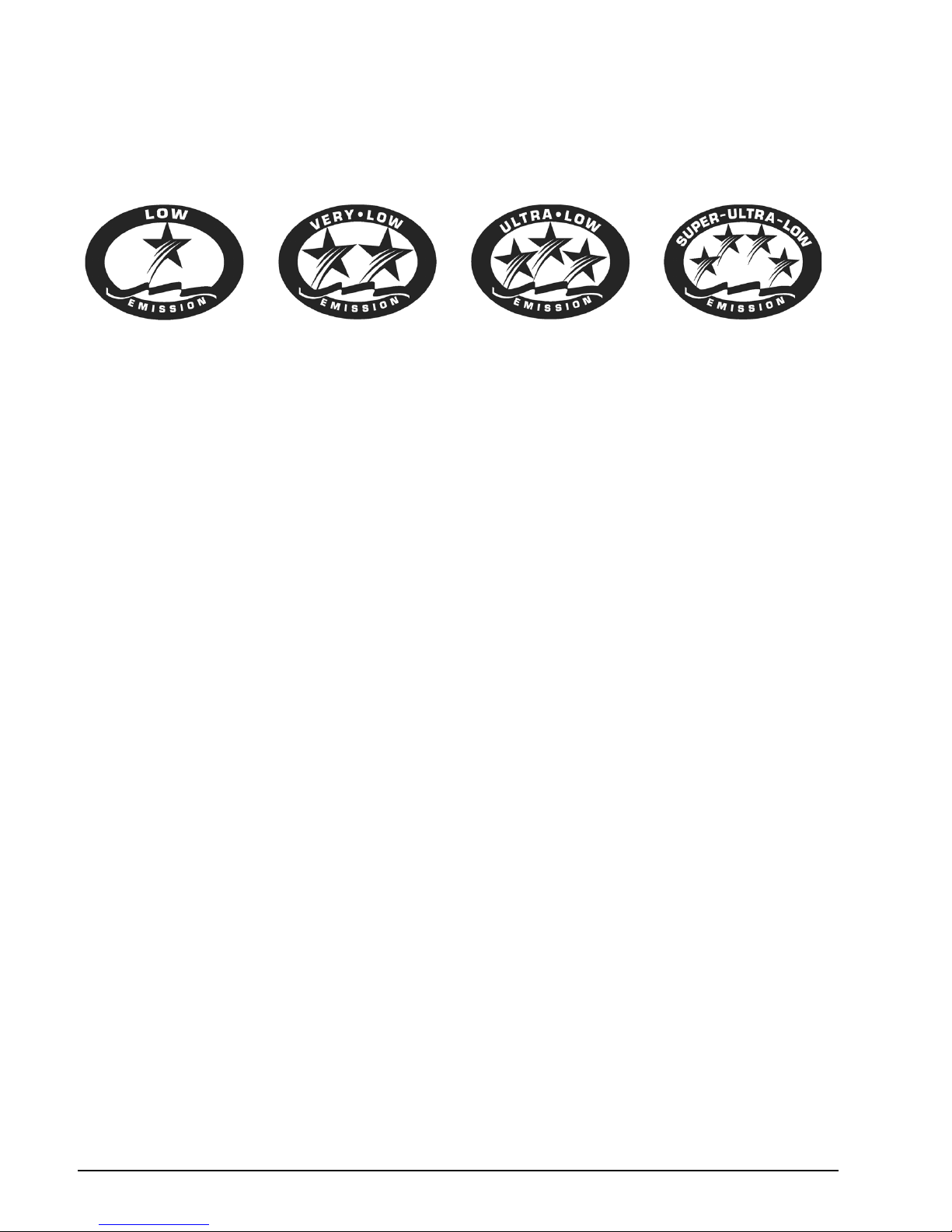
68
California Emission Control Warranty Statement
Your Evinrude E-TEC G2 outboard has a special environmental label required by the California Air Resources Board. The label has one, two, three, or four stars. A hangtag, provided with your outboard, describes the meaning of the star rating system.
The Star Label Means Cleaner Marine Engines
The Symbol for Cleaner Marine Engines:
Cleaner Air and Water
For a healthier lifestyle and environment.
Better Fuel Economy
Burns up to 30 to 40 percent less gas and oil than conventional carbureted two-stroke engines,
saving money and resources.
Longer Emission Warranty
Protects consumer for worry free operation.
One Star – Low Emission
The one-star label identifies Personal Watercraft, Outboard, Sterndrive and Inboard engines that meet the
Air Resource Board's Personal Watercraft and Outboard marine engine 2001 exhaust emission standards. Engines meeting these standards have 75% lower emissions than conventional carbureted twostroke engines. These engines are equivalent to the U.S. EPA's 2006 standards for marine engines.
Two Stars – Very Low Emission
The two-star label identifies Personal Watercraft, Outboard, Sterndrive and Inboard engines that meet the
Air Resources Board's Personal Watercraft and Outboard marine engine 2004 exhaust emission standards. Engines meeting these standards have 20% lower emissions than One Star – Low Emission engines.
Three Stars – Ultra Low Emission
The three-star label identifies engines that meet the Air Resources Board's Personal Watercraft and Outboard marine engine 2008 exhaust emission standards or the Sterndrive and Inboard marine engine 2003
exhaust emission standards. Engines meeting these standards have 65% lower emissions than One Star
– Low Emission engines.
Four Stars – Super Ultra Low Emission
The four-star label identifies engines that meet the Air Resources Board's Sterndrive and Inboard marine
engine 2009 exhaust emission standards. Personal Watercraft and Outboard marine engines may also
comply with these standards. Engines meeting these standards have 90% lower emission than One Star
– Low Emission engines.
For more information: Cleaner Watercraft – Get the Facts
1-800-END-SMOG
www.arb.ca.gov
Page 73

69
PRODUCT WARRANTY INFORMATION
Your Emission Control Warranty Rights and Obligation
The California Air Resources Board and Bombardier Recreational Products (“BRP”) are pleased to explain the emission control system warranty on your Evinrude E-TEC G2 outboard. In California, new outboard engines must be designed, built, and equipped to meet the State's stringent anti-smog standards.
BRP must warrant the emission control system on your outboard for the periods of time listed below provided there has been no abuse, neglect, or improper maintenance of your outboard.
Your emission control system may include parts such as the carburetor or fuel injection system, the ignition system, and catalytic converter. Also included may be hoses, belts, connectors, and other emissionrelated assemblies.
Where a warrantable condition exists, BRP will repair your outboard at no cost to you including diagnosis,
parts, and labor provided that such work is performed by an authorized BRP dealer.
Manufacturer's Limited Warranty Coverage
This emission limited warranty covers Evinrude outboards certified and produced by BRP for sale in California, that are originally sold in California to a California resident, or subsequently warranty-registered to
a California resident. The BRP U.S. and Canada limited warranty conditions for Evinrude outboards are
still applicable to these models with the necessary modifications.
Select emission control parts of your Evinrude E-TEC G2 outboard are warranted from the date of purchase by the first retail consumer or the date the product is first put to use, whichever occurs first, for a
period of: 4 years, or for 250 hours of use, whichever occurs first.
However, warranty coverage based on the hourly period is only permitted for outboards equipped with the
appropriate hour meters or their equivalent. If any emission-related part on your engine is defective under
warranty, the part will be repaired or replaced by BRP.
Parts covered are:
The emission warranty covers damage to other engine components that is caused by the failure of a warranted part.
The BRP Operator's Guide provided contains written instructions for the proper maintenance and use of
your outboard. All emission warranty parts are warranted by BRP for the entire warranty period of the outboard, unless the part is scheduled for replacement as required maintenance in the Operator's Guide.
1. Electrical System 4. Air Induction System
A. EMM (Engine Management Module) A. Reed Valves
B. Spark Plugs and Wires B. Throttle Body Assembly
C. Ignition Coils C. Intake Manifold
D. Wiring Harness
5. Oil System
2. Exhaust System
A. Oil Injector
A. Inner Exhaust Housing B. Oil Lines, Fittings, and Clamps
B. Adapter (Exhaust Manifold)
C. Megaphone (Inner Exhaust)
6. Sensors
A. Air Temperature Sensor
3. Fuel System
B. Crank Position Sensor
A. Fuel Lift Pump C. Throttle Position Sensor
B. Fuel Supply Pump D. Water Temperature Sensor
C. Fuel Injectors E. Thermostat
D. Vapor Separator
E. Fuel Lines, Fittings, and Clamps
7. Gaskets
A. All Emission Component Gaskets
Page 74

70
Emission warranty parts that are scheduled for replacement, as required maintenance, are warranted by
BRP for the period of time before the first scheduled replacement date for that part. Emission warranty
parts that are scheduled for regular inspection but not regular replacement are warranted by BRP for the
entire warranty period of the outboard. Any emission warranty part repaired or replaced under the terms
of this warranty statement is warranted by BRP for the remainder of the warranty period of the original
part. All parts replaced under this limited warranty become the property of BRP.
Maintenance receipts and records should be transferred to each subsequent owner of the outboard.
Owner's Warranty Responsibilities
As the outboard owner, you are responsible for the performance of the required maintenance listed in your
Operator's Guide. BRP recommends that you retain all receipts covering maintenance on your outboard,
but BRP cannot deny warranty solely for the lack of receipts or your failure to ensure the performance of
all scheduled maintenance.
As the outboard owner, you should however be aware that BRP may deny you warranty coverage if your
outboard or a part has failed due to abuse, neglect, improper maintenance, or unapproved modifications.
You are responsible for presenting your outboard to an authorized BRP dealer as soon as a problem exists. The warranty repairs will be completed in a reasonable amount of time, not to exceed 30 days.
For any questions regarding your warranty rights and responsibilities or for the name and location of the
nearest authorized BRP dealer, contact:
BRP US Inc. / Marine Propulsion Systems,
After Sales Support,
P.O Box 597,
Sturtevant, WI 53177,
1-262-884-5993
or visit www.evinrude.com.
Page 75

71
Readiness Test
The Operator’s Readiness Test....
1. Did you read this Guide from front cover to rear cover?
2. Are you ready to take responsibility for the safe operation of your boat and outboard?
3. Do you understand all the safety precautions and instructions contained in this Guide?
4. Do you understand that this Guide contains essential information to help prevent personal
injury and damage to equipment?
5. Are you ready to follow the recommendations in this Guide and take a boating safety
course before you operate your boat and outboard?
6. Do you know who to ask if you have any questions about your boat and outboard?
7. Do you know your local marine traffic laws?
8. Do you understand that human error can be caused by carelessness, fatigue, overload,
preoccupation, unfamiliarity of operator with the product, drugs and alcohol, just to name
a few?
WARNING
It is impossible for this Guide to cover every hazardous situation you may encounter;
however, your understanding of and adherence to essential information contained in
this Guide will build good judgment when boating. Always be alert and careful: a
good foundation for safety.
Page 76
72
Page 77

73
Frequently Asked Questions
No dealer-scheduled maintenance for five years or 500 hours of normal recreational use?
Really?
• Yes! BRP knows you want to spend your time out on the water, not servicing your Evinrude E-TEC G2
outboard. There are no valves to adjust, belts to service, chains to replace, or oil to change. We do recommend pre-launch inspections of your outboard at each use and at regular intervals. Salt water applications require minimal additional inspections and lubrication.
What fuel octane is recommended for my Evinrude E-TEC G2 outboard?
• Evinrude E-TEC G2 outboards require a minimum octane rating 87 {AKI (R+M)/2} in the U.S. and Can-
ada, or 90 {RON} outside of the U.S. and Canada. Use of higher octane fuels is not harmful, but also
not necessary.
What kind of oil does my Evinrude E-TEC G2 outboard require?
• Evinrude XD100 Direct Injection Oil and Evinrude XD50 2–Stroke Oil are recommended for your Evin-
rude E-TEC G2 outboard. When operating in conditions under 32°F (0°C), Evinrude XD100 oil must be
used.
Do I need to mix oil into my fuel?
•No. Evinrude E-TEC G2 outboards do not require any mixing of oil and fuel.
Can I order replacement parts and accessories for my Evinrude E-TEC G2 outboard?
• Yes. When replacement parts are required, use Evinrude Genuine Parts or parts with equivalent char-
acteristics, including type, strength, and material. Using substandard parts could result in injury or product malfunction. Your dealer can order the parts and accessories you desire.
Do I need to complete any paperwork when I move or sell my Evinrude E-TEC G2 outboard?
• Yes. In order to maintain contact with you or the new Evinrude E-TEC G2 owner, BRP requests you
complete the form outlining
Change of Address / Change of Ownership on page 75. This will
ensure you or the new owner is made aware of any product announcements and keep the warranty coverage up-to-date.
What do I need to do before storing my Evinrude E-TEC G2 outboard for the winter?
• Winterization is minimal. Refer to Storage on page 44 for step-by-step instructions to store your Evin-
rude E-TEC G2 outboard for the off-season.
Page 78
74
Page 79
75
Change of Address / Change of Ownership
If your address has changed or if there has been a change of ownership, be sure to fill out and mail the
form provided on this page.
This notification is necessary for your own safety even after expiration of the original warranty, since BRP
will be in a position to contact you if correction to your outboard is required. Outside the U.S. and Canada,
this card should be sent to the Bombardier Recreational Products division where the outboard was registered. Please contact your Dealer or Distributor.
Change of Address Change of Ownership
Model number
Serial Number
Old Address / Previous Owner
Last name
First name M.I.
Address
City State
Zip code Country
Phone number
Signature Date
New Address / New Owner
Type of Use Recreational Commercial Government
Last name
First name M.I.
Address
City State
Zip code Country
Phone number
Signature Date
Dealer Information
Dealer name
Dealer number
Phone number
Contact name
In the U.S. or Canada, mail completed form to: BRP US Inc. / Marine Propulsion Systems
After Sales Support
P.O Box 597
Sturtevant, WI 53177
Page 80
76
Page 81
77
Confirmation of Receipt
Your Dealer
Upon delivery of your new Evinrude outboard, complete and sign the form below. Your Dealer will take
receipt of the form for their records.
Receipt
Name:
Address:
Name:
Address:
Owner of Model No:
Serial No:
(To be completed by customer or selling Dealer)
The Dealer named on this document has instructed me on the operation, maintenance, safety
features and warranty policy, all of which I understand and agree to be bound with. I am also satisfied
with the predelivery set-up and inspection of my Evinrude outboard. I have also received a copy of
the Operator’s Guide.
Signature:
Date:
Page 82
78
Page 83

Page 84
© 2015 Bombardier Recreational Products Inc. All rights reserved. ®, TM and the BRP logo are trademarks of Bombardier Recreational Products or its affiliates
 Loading...