

Page 1
Page 2

TABLE of CONTENTS
1. PRODUCT OVERVIEW ......................................................................................................................................................... 4
1.1 What’s Included ................................................................................................................................................... 4
1.2 Safety Instructions .............................................................................................................................................. 5
1.3 Product Views ...................................................................................................................................................... 6
2. INTERVIEW SPECIFICATIONS ......................................................................................................................................... 9
2.1 InterView Technical Specifications ................................................................................................................... 9
2.2 Preset Timing Modes ........................................................................................................................................ 10
2.3 Power Management Modes .............................................................................................................................. 10
3. SETTING UP INTERVIEW ................................................................................................................................................ 11
3.1 Steps to Assembling InterView ....................................................................................................................... 11
3.2 Connecting InterView to a PC ......................................................................................................................... 13
3.3 Plug and Play Compatibility ............................................................................................................................. 15
4. HOW TO ADJUST INTERVIEW ........................................................................................................................................ 16
4.1 Rotating/Folding ................................................................................................................................................ 16
4.2 Control Buttons .................................................................................................................................................. 17
4.3 Brightness Adjustment ..................................................................................................................................... 17
4.4 Auto Adjustment ................................................................................................................................................ 17
5. SYSTEM REQUIREMENTS AND SOFTWARE INSTALLATION .................................................................................. 18
5.1 System Requirements ....................................................................................................................................... 18
5.2 Installing the Webcam Software ..................................................................................................................... 18
5.3 Using the InterView Camera Application ....................................................................................................... 22
6. TROUBLESHOOTING ......................................................................................................................................................... 27
6.1 Self-Test Feature Check ................................................................................................................................... 27
6.2 FAQs .................................................................................................................................................................... 27
7. SERVICE INFORMATION ................................................................................................................................................. 30
7.1 Product Registration and Customer Support ................................................................................................. 30
7.2 Pixel Policy .......................................................................................................................................................... 30
2
Page 3

7.3
Warranty Terms and Conditions ..................................................................................................................... 31
8. COMPLIANCE INFORMATION ........................................................................................................................................ 33
8.1 FCC Notice .......................................................................................................................................................... 33
9. LEGAL INFORMATION ...................................................................................................................................................... 34
9.1 Trademark Information .................................................................................................................................... 34
9.2 Software License Agreem ent ........................................................................................................................... 34
9.3 Rights .................................................................................................................................................................. 34
3
Page 4
1. PRODUCT OVER VIE W
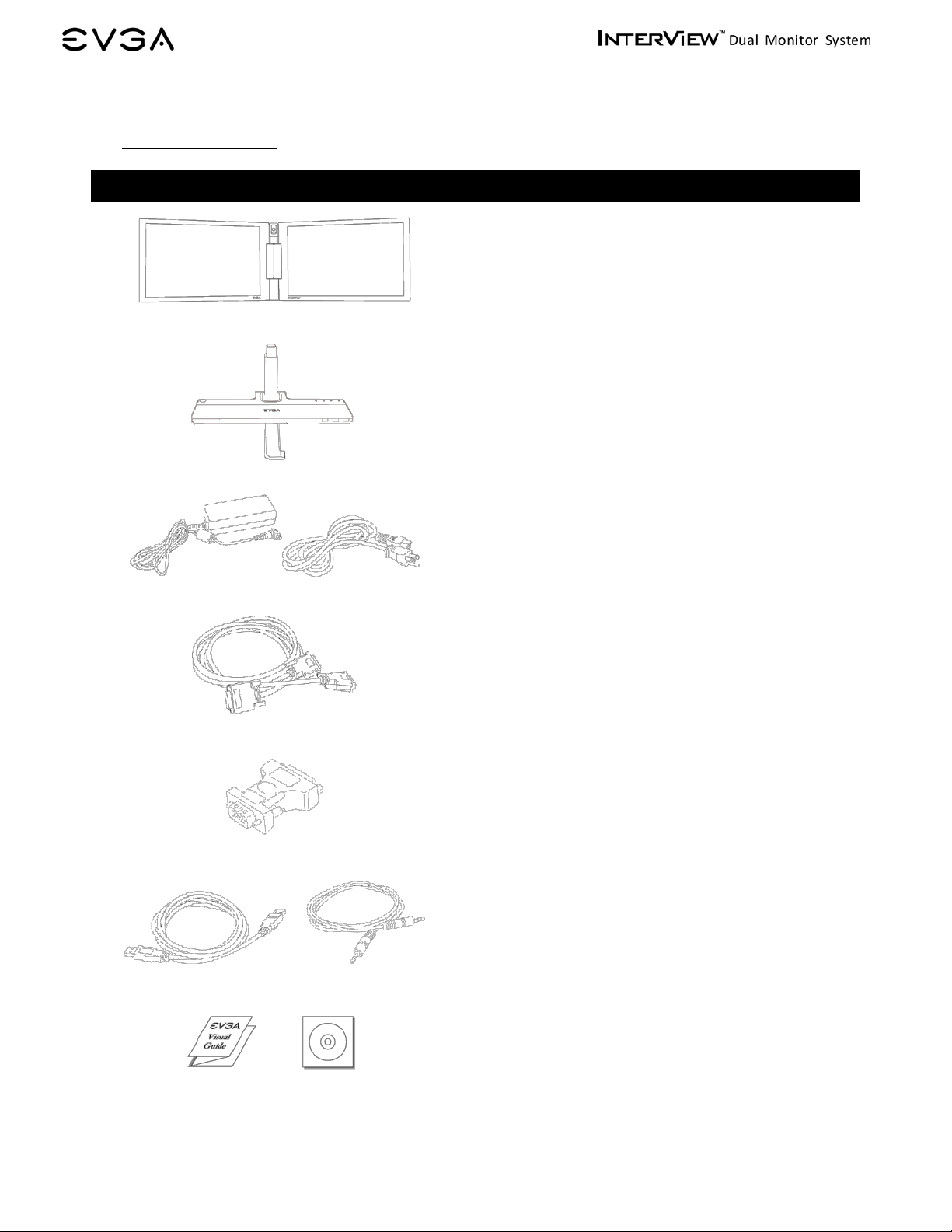
1.1 What’s Included
The following items are included wit h InterView:
InterView Monitor:
Dual – 17 Inch – LCD Panels
InterView Multiplatform Control Base
AC Power Adapter
Power Cord
DMS to DUAL DVI-I Signal Cable
DVI-I to VGA Adapter
Microphone Audio Cable
4
Drivers and Software CD
USB Cable
Visual Guide
Page 5
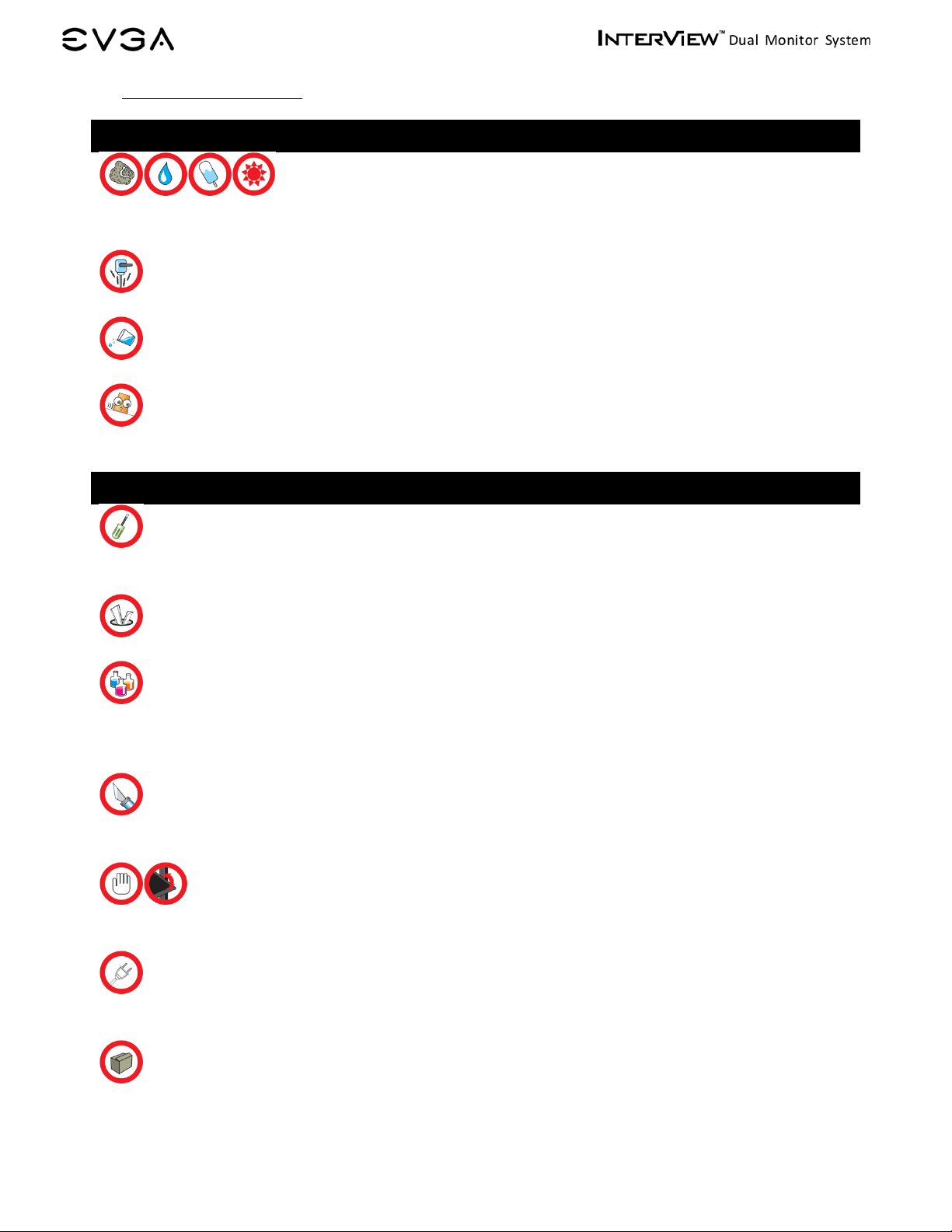
1.2 Safety Instruc tions
Safe Environment
Do not store or use the InterView in locations that are exposed to heat, extreme col d, high
humidity or dusty environment. Room temperature conditions are recommended.
Do not subject InterView to severe vibrations or high impact conditions.
Do not allow water or other liquids to spill on or into InterView.
InterView may become unstable if not placed on a solid and horizontal surfac e.
Safe Use
To avoid electric shock, never touch t he c omponents inside of InterView. Only a quali fied
technician should open the monitor case.
Do not try to insert anything metallic or push objects into any openings.
Do not use benzene, thinner, ammonia, abrasive cleaners, or compressed air as t hese will
cause damage to the LCD screens. If possi ble, use a special screen-cleaning tissue or
solution suitable for the anti-static coating.
Handle your monitor with care as darker-colored plastics may scratch and show sc uff
marks.
Keep hands off the gap between the stand and the panel as injury may take place while
rotating or folding the LCD port ion of InterView.
Unplug the monitor when it is going to be left unused for an extended period of time or
before any type of service is performed.
Consider keeping the packaging for use in the future when you may need to transpor t the
monitor. The fitted foam packing is ideal for protecting the monitor during transport.
5
Page 6
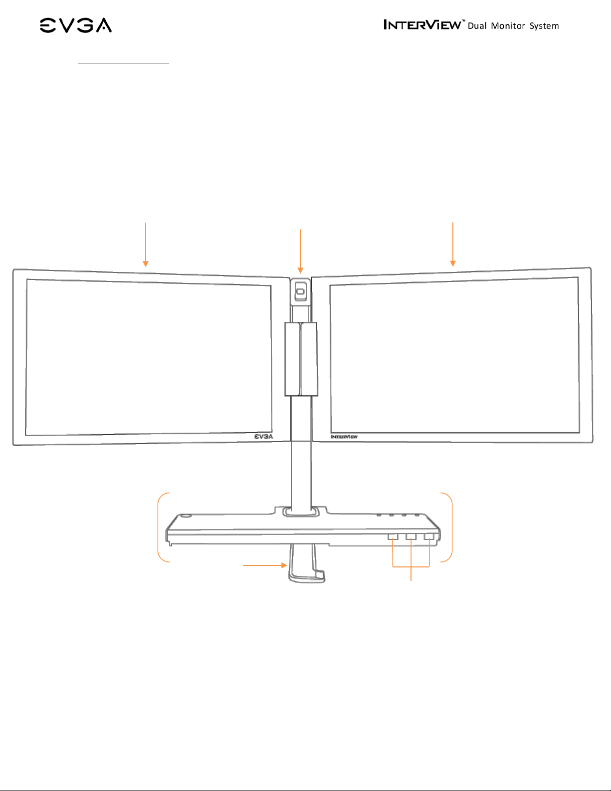
3 1 2 5
1.3 Product Views
Panel Front View
1. Integrated Webcam
2. Balance Bar
3. Multiplatform Control Base
4. Integrated 3-Port USB 2.0 Hub
5. 17 Inch LCD Panels
5
4
6
Page 7
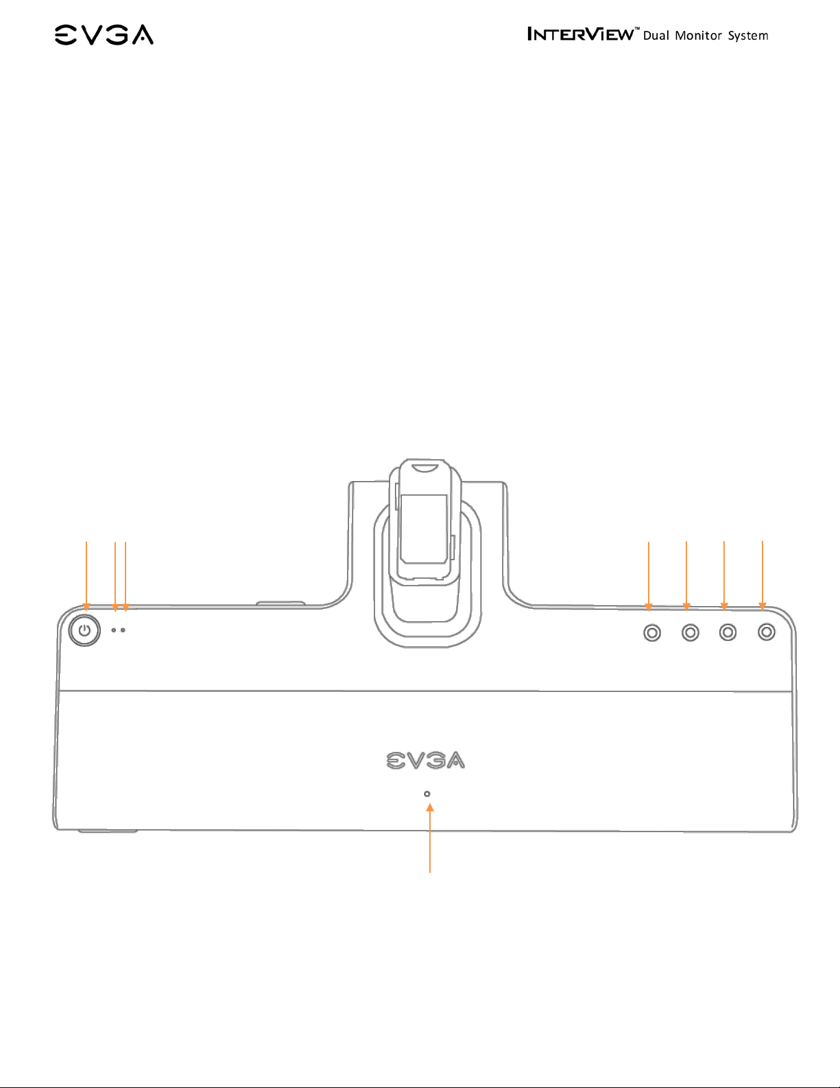
Control Base Front View
1. Power Button
2. Power Light Indicator (Left Panel)
3. Power Light Indicator (Right Panel)
4. Panel Selection Button
5. Brightness Adjust (Down)
6. Brightness Adjust (Up)
7. Auto Adjust
8. Integrated Microphone
2
1
3
8
5
4
7
6
7
Page 8
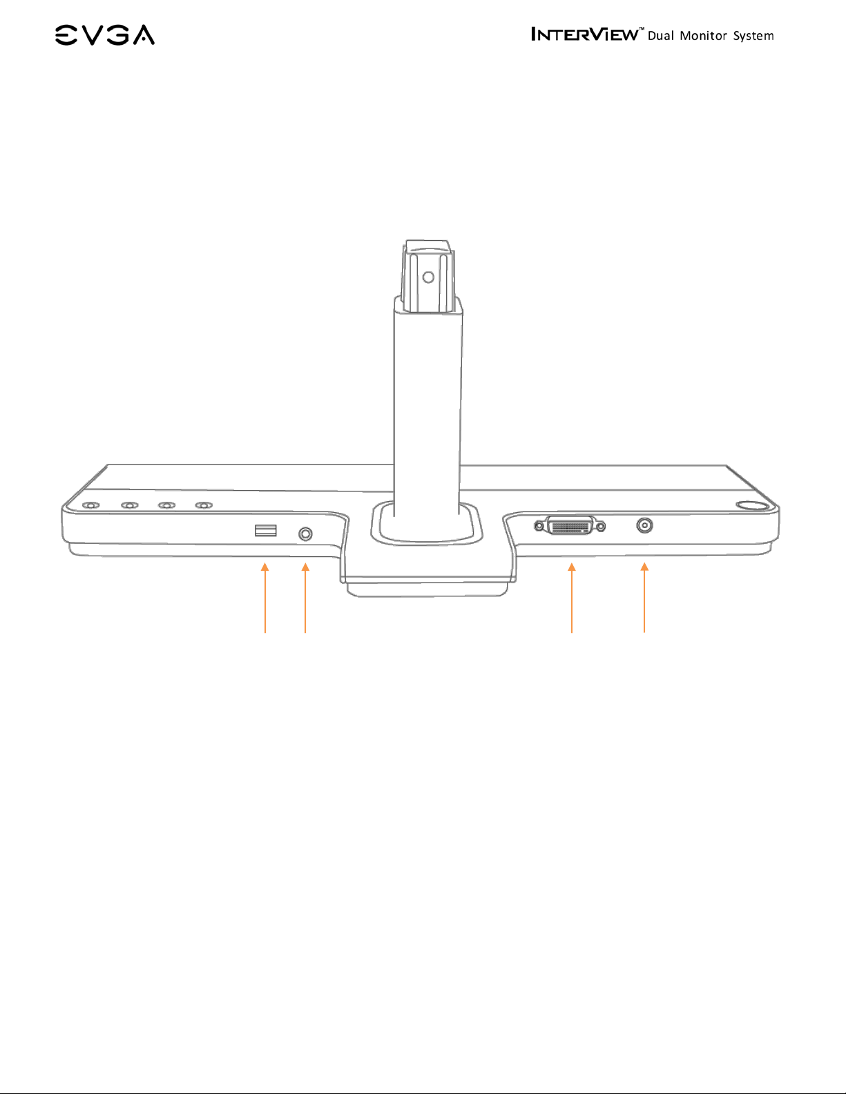
Control Base Back View
1. USB to PC Port
2. Microphone Jack
3. DMS Port
4. AC Power Connector
1
2
3
4
8
Page 9

General
LCD
Vertical
229.50 mm
Vertical
56 Hz to 76 Hz
Horizontal
20° / 35° (CR=10)
White luminance
220 typ.
Contrast ratio
500:1 typ.
Resolution
Optimal preset resolution
1440x900*2 @ 60 Hz
Bezel Opening Dimension
369 x 188 x 870 mm
Environmental
Humidity
30% to 80% (non-condensing)
Temperature
-10° to 60°C
Humidity
10% to 85% (non-condensing)
2. INTERVIEW SPECIFIC AT I ON S
2.1 I nte r View Technic al Specifications
Model number EVGA InterView 1700
Screen type 17’’Wide TFT
Preset display area
Horizontal 367.20 mm
Synchronization
Horizontal 31.5 kHz to 81.1 kHz
Viewing angle
Vertical 45° / 45° (CR=10)
Pixel pitc h 0.255 X 0.255 mm
Response Time 8ms typ. (14ms typ. max)
Highest preset resolution 1440x900*2 @ 60 Hz
Physical Characteristics
Dimensions
Bezel Closing Dimension 417 x 485 x 390 mm
Weight 7.5 kg/16.52 lbs
Operating
Temperature 5° to 35°C
Non-operating
9
Page 10

Horizontal Frequency
Vertical Frequency
Sync Polarity
VESA, 640x480
31.469
59.940
25.175
-/-
VESA, 800x600
46.875
75
49.500
+/+
VESA, 1024x768
48.363
60.004
65.000
-/-
VESA, 1280x1024
63.981
60.020
108.000
+/+
VESA, 1280x1024
79.976
75.025
135.000
+/+
VESA, 1440x900
55.935
59.887
106.500
-/+
Normal operation
Active
Active
Active
Blue
Active-off mode
Inactive
Inactive
Blanked
Amber
2.2 Prese t Timing Modes
The screen will be adjusted automatically when the signal transferred from the computer is
the same as the following Preset Timing Modes. If your display mode is not listed, it is not
supported by this monitor; the screen may go blank while the power LED is on.
Display Mode
VESA, 640x480 37.500 75 31.500 -/VESA, 800x600 37.879 60.317 40.000 +/+
VESA, 800x600 45.072 72 46.875 +/+
VESA, 1024x768 60.023 75.029 78.750 +/+
VESA, 1152×864 67.500 75.000 108.000 +/+
VESA, 1440x900 70.635 74.984 136.750 -/+
(kHz)
(Hz)
Pixel Clock (MHz)
(Horizontal/Vertical)
2.3 Power Management Modes
For energy conservation, InterView has built-in power management that saves energy by
switching itself to low-power mode when it has not been used for a certain amount of time.
It automatically returns to normal op erat i on when the users press a key on the keyboard. It
is recommended to turn InterView OFF when it is not needed o r when leaving it unattended
for long periods of time.
VESA Modes Horizontal Sync Vertical Sync Video Power Indicator
Switch off n/a n/a n/a Off
10
Page 11

3. SETTING UP INTERVIEW
Read the safety instructions before setting up the InterView.
3.1 Step s to Assembling InterView
1. Rotate the balance bar out from the bottom of the base:
2. Remove the caps on t he stand and the panel:
3. Assemble the stand and the panel:
11
Page 12

4. Push in the button and turn it c l ockw ise to lock up the stand and the panel:
5. Open up the panel:
6. Push the balance bar back into the base:
12
Page 13

3.2 Connecting InterView to a PC
Before setting up InterView, you must power down your computer(s).
1. Connect the monitor to a computer(s) using the DMS to Dual DVI-I cord.
Note: You can use either the D-Sub plug or the DVI-D plug if there’s no available
DVI-I port on your PC.
2. Plug the power cord into the power adapter:
3. Connect the monitor to the electrical outlet using the power cord:
13
Page 14

4. Power on InterView and the computer(s):
5. Use the audio cable to connect Int erView to the MIC or Line-in input of the computer.
This is required to use the onboard microphone.
6. Connect InterView to the computer(s) with the USB cable to enable the front USB 2.0
HUB located on t he monitor base. This is also required to use t he onboard webcam.
14
Page 15

3.3 Plug and Play Compatibility
You can use InterView with any Plug and Play compatible system. The system configures
itself and optimizes the display’s settings. In most cases, InterView‘s installation is
automatically processed unless the user intervenes.
15
Page 16

4. HOW TO ADJUST INTERVIEW
4.1 Rotating/Folding
Each panel can rotate 180 degrees. The display will automatically adjust to the co r r ect
position.
Each panel can be opened and closed 90 degrees horizontally.
16
Page 17

4
4.2 Control Buttons
1
1. Power Button: Powers the InterView ON or OFF
2. Panel Selection Button: Selects the monitor to be adjusted
3. Brightness Adjust (Down): Decreases brightness levels
4. Brightness Adjust (Up): Increases brightness levels
5. Auto Adjust: Adjusts vertical position, phase, horiz ontal position, and pixel clock
automatically
3
2
5
4.3 Brightness Adjustment
Users can adjust the monitor brightness l evels from the Brightness (Up/Down) buttons. The
Brightness levels can be adjusted fr om level 0 to level 8 and will be displayed on the screen
while adjusting. Press the Panel Selection Button to select the panel to be adjusted.
4.4 Auto Adjustment
Users can obtain a n optimal display when using the AUTO key function. When the 'AUTO'
button is pressed, InterView will optimize the currently selected pan el.
Auto Adjustment is disabled when using a DVI connection or DVI dongle.
17
Page 18

5. SYSTEM REQUIREMENTS AND SOFTWARE INSTALLATION
5.1 System Requirements
Operating Systems Supported:
- Windows XP Home Edition
- Windows XP Professional
- Windows XP Professional X64 Edition
- Windows Vista™
- Windows Vista™ 64-bit
Hardware:
- 64MB of System Memory or more
- 50MB Hard Disk space or more
Others:
- Microsoft DirectX 9.0C
5.2 Installing the Webcam Software
Some functions provided in InterView Application may not work if the driver is not
installed properly
(Step 1) Before the Installation
- View the Device Manager to check if the InterView webc am has already installed. Select
Start (XP)Run or (Vista)Search Box type
Manager window will appear. Expand “Imaging Devices” to reveal the device name:
UVC PC Camera.
devmgmt.msc
Click OK. The Device
USB2.0
- Insert the InterView CD into the disc drive. The AutoPlay dialogue box will appear.
- Click Run autorun.exe
18
Page 19

(Step 2) Processing Installation
- Click
Webcam software installatio n
to start the installation process
- Click
Next,
select the application you would like to i nstall, then click
Next
to continue
Note: For users who select to install both webcam driver and application, the installation will
starts from the webcam software then to the webcam driver.
Installing the Webcam Application
- Select the destination folder then click
Install
to begin the installation
19
Page 20

- Installation in process, the dialogue box will automatically close when the insta l lation
completes.
Installing the Webcam Driver
- Click Install
- Click Install
20
Page 21

- Click
Finish
then select the option to rest art you computer after the installation completes
Note: Depending on each user’s PC system and hardware performance, it may take 10 to 15
seconds before enter ing to the next step, please be patient.
- Click
Finish
to exit the wizard, then the computer will automat ical ly r est art.
(Step 3) Self Check
To ensure the driver has successfully installed, visit the Device Manag er to check if the device
name has changed to
InterView USB 2.0 Webcam.
You can find the InterView Control Center
under Programs when after the InterView camera application is successfully installed
21
Page 22

3
5 6
5.3 Using the InterView Camera Application
Main Panel Layout
4
2
7
1
1. Display screen
2. Record
3. Snapshot
4. Color setting page
5. Snapshot setting page
6. Record setting page
7. Misc setting page
22
Page 23

2
9
Color Setting Page
This panel allows users to adjust the color settings by dragging the track bars.
1
3
4
5
1. Brightness adjustment
2. Contrast adjustment
3. Hue adjustment
4. Saturation adjustment
5. Sharpness adjustment
6. White balance adjustment
7. Gamma adjustment
8. Color / Gray scale
9. Backlight compensation
6
7
8
23
Page 24

2
Snapshot Setting Page
The InterView webcam application allows users to capture a single photo as well as continuous
shooting. In this panel, the application allows users to set snapsho t functions, such as time
intervals and output formats.
1
3
4
5
1. Photo quantity for continuous shooting (1-30)
2. Time intervals for continuous shooting (500ms – 2000ms)
3. Image format. Options are: BMP / JPEG / GIF
4. Destination file for images
5. Shutter
24
Page 25

2
Record Setting Page
This panel allows adjustments to the recording function of the webcam.
1
3
5
1. Select the audio device to be captured
2. Select the audio recording source. Ex: Microphone
3. Select the audio en coder to encode the au dio stream
4. Select the video enc oder to encode the video stream
5. Set file limits
6. Set time limits
7. Recording file save path
4
6
7
25
Page 26

2
Misc Setting Page
Within this panel, users can adjust settings that c ontrol different aspects of the image.
1
3
4
1. Video Flip: Flips the video horizontally/vertically
2. Exposure control
- Low Light: avoid under-exposure in low light environment
- High Light: avoid under-exposure in high light environment.
3. Flicker Reduction: Avoids flicker
4. Picture Quality: Select for better quality or faster speed.
26
Page 27

Symptoms
Possible Solutions
Check connection integrity at bot h ends of the video cable
Increase brightness via OSD
6. TROUBLESHOOTING
6.1 Self-Test Feature Check
Self-Test Feature Check (STFC) allo ws users to check if the monitor works properly.
1. Turn off both your computer and the mo ni tor
2. Unplug the DMS cable from the back of the computer
3. Turn on the monitor
4. If the monitor is functioning pro perly, you will see a box in the illustratio n below
This box appears during normal operation if the video cable becomes disconnect ed or
damaged.
5. Turn off your monitor and reconnect the video cable; then turn on both your computer
and the monitor.
6. If the power indicator remains orange after using the previous procedure, check your
VGA card, cable, and computer system; your monitor is functioning properly.
6.2 FAQs
Before calling for assistance, check the information in this section to see if you can
remedy any problems yourself.
No picture
No picture or no brightness
Picture is fuzzy, blurry or ghosting
•
• Electric outlet verification
• Ensure power button is depressed fully
•
• Perform monitor self-test feature check
• Check for bent or broken pins
• Auto Adjust via OSD
• Eliminate video extension cables
• Perform monitor reset
• Lower video resolution or increase font size
27
Page 28

Auto Adjust via OSD
Cycle power on-off
Cycle power on-off
Wavy picture or fine movement
LCD screen has spots
LCD screen has bright spots
Picture too dim or too bright
•
• Perform monitor reset
• Check environmental factors
• Relocate and test in another room
•
• These are pixels that are permanently off and is a natural defect
that occurs in LCD technology
•
• These are pixels that are permanently on and is a natural defect
that occurs in LCD technology
• Perform monitor reset o n "Fa ctory Reset"
• Auto Adjust via OSD
• Adjust brightness via OSD
Screen not centered correctly
Screen has one or more lines
Screen is scrambled or appears
torn
Visible signs of smoke or sparks
• Perform monitor reset o n "Display Reset"
• Auto Adjust via OSD
• Adjust brightness via OSD
• Ensure monitor is in proper video mode
• Perform monitor reset o n "Display Reset"
• Auto Adjust via OSD
• Perform monitor self-test feature check a nd determine if these
lines are also in self-test mode
• Check for bent or broken pins
• Perform monitor reset o n "Display Reset"
• Auto Adjust via OSD
• Perform monitor self-test feature check to determine if scrambled
screen appears in self-test mode
• Check for bent or broken pins
• Boot up in the "safe mode"
• Do not perform any troubleshooting steps
• Monitor needs to be replaced
Monitor malfunctions on & off
• Ensure monitor is in proper video mode
• Ensure video cable connect i o n t o computer and to the flat panel is
secure
• Perform monitor reset o n "Fa ctory Reset"
• Perform monitor self-test feature check to determine if the
intermittent problem occurs in self-test mode
28
Page 29

Perform monitor self-test feature check
Use the Power Management feature to turn off the monitor at all
Picture missing color
Picture color not good
•
• Check connection integrity at both end of the video cable
• Check for bent or broken pins
• Change the color to "PC Custom Color" or "MAC Custom Color"
• Adjust R/G/B value of "PC Custom Color" or "MAC Custom Color"
• Change the Color Format to "PC RGB" or "YPbPr" (for Video/DVI-
HD inputs)
Faint shadow from the static image
displayed appears on the s cr e en
•
times when not in use
• Alternatively, use a dynamically changing screen sav er
29
Page 30

7. SERVICE INFORMATION
7.1 Product Registration and Customer Support
Should you require any assistance with the installation or troubleshooting of the EVGA
InterView, please visit the Support section of our website at www.evga.com/support. There
you’ll be able to download drivers, c hec k out our extensive Knowledge Base, and submit
technical and customer support inquiries. Be sure to visit the EVGA community message
boards: http://forums.evga.com
Contact our Customer Service through email to get all of your questions answered and
problems resolved – it’s fast, it’s easy, and it works! If you require immediate assistance,
please contact our Customer Service at 888.880.EVGA (3842).
Point your browser to www.evga.com/register and have the following information ready
before contacting customer service:
-Product Name & Part Number
-UPC Number
-Serial Number
The EVGA Advanced RMA (EAR) Program is a program to protect yourself and your product
in the case of product failure. For more details please visit:
www.evga.com/EAR
7.2 Pix el Policy
The EVGA monitor is evaluated on the number of acceptable non-performing pixels and the
distance between each non-performing pixels. The terms “non-performing” and “defective
pixels/sub-pixels” are used interchangeably for ease of identification. All monitors have been
tested to ensure they comply with this standard.
To identify non-performing pixels, the monitor shall be viewed under normal operating
conditions, preferably in its native resolution, and from a normal viewing distance of at least
50 cm (16 in.).
During the LCD Monitor manufacturing process, it is not uncommon for one or more pixels to
become fixed in an unchanging state. The visible result is a fixed pixel that appears as an
extremely tiny dark or bright discolored dot. When the pixel remains permanently lit, it is
known as a “bright dot.” When the pi xel remains black, it is known as a “dark dot.”
In almost every case, these fixed pixels are hard to see and do not detract from display
quality or usability. A display with 1 to 5 bright or dark dots is considered normal and within
industry standards.
30
 Loading...