

Page 1

XRF1/XRF1A 16x16 RF Router
User Manual
© Copyright 2006 - 2009
EVERTZ MICROSYSTEMS LTD.
5288 John Lucas Drive
Burlington, Ontario,
Canada,
L7L 5Z9
Phone: 905-335-3700
Sales: [email protected] Fax: 905-335-3573
Tech Support: [email protected] Fax: 905-335-7571
Web Page: http://www.evertz.com
Version 1.2 October 2009
The material contained in this manual consis ts of information that is the propert y of Evertz Micros ystems and is i ntended solel y for
the use of purchasers of the X1200 and X0601 Series Route rs. Evertz Microsystems expr essly pro hibits the use of this manu al for
any purpose other than the operation of the Routers.
All rights reserved. No part of this publication may be reproduced without the express written permission of Evertz Microsystems
Ltd. Copies of this guide can be ordered from your Evertz products dealer or from Evertz Microsystems.
Page 2

Page 3
IMPORTANT SAFETY INSTRUCTIONS
S
O
T
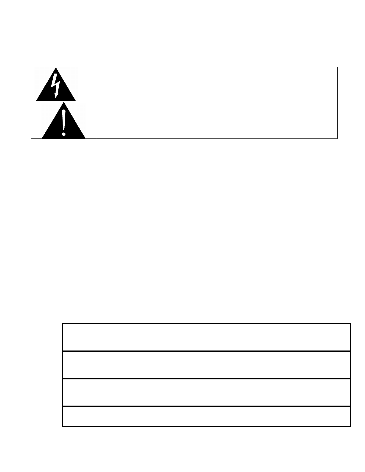
The lightning flash with arrowhead symbol within an equilateral triangle is
intended to alert the user to the presence of uninsulated “Dangerous voltage”
within the product’s enclosure that may be of sufficient magnitude to constitute a
• Read this information.
• Keep these instructions.
• Heed all warnings.
• Follow all instructions.
• Do not use this apparatus near water.
• Clean only with dry cloth.
• Do not block any ventilation openings. Install in accordance with the manufacturer’s
instructions.
• Do not install near any heat sources such as radiators, heat registers, stoves, or other
apparatus (including amplifiers) that produce heat.
• Do not defeat the safety purpose of the polarized or grounding type plug. A polarized plug has
two blades with one wider than the other. A grounding type plug has two blades and a third
grounding prong. The wide blade or the third prong is provided for your safety. If the provided
plug does not fit into your outlet, consult an electrician for replacement of the obsolete outlet.
• Protect the power cord from being walked on or pinched particularly at plugs, convenience
receptacles and the point where they exit from the apparatus.
• Only use attachments/accessories specified by the manufacturer.
• Unplug this apparatus during lightning storms or when unused for long periods of time.
• Refer all servicing to qualified service personnel. Servicing is required when the apparatus has
been damaged in any way, such as power-supply cord or plug is damaged, liquid has been
spilled or objects have fallen into the apparatus, the apparatus has been exposed to rain or
moisture, does not operate normally, or has been dropped.
risk of electric shock to persons.
The exclamation point within an equilateral triangle is intended to alert the user to
the presence of important operating and maintenance (Servicing) instructions in
the literature accompanying the product.
WARNING
TO REDUCE THE RISK OF FIRE OR ELECTRIC – SHOCK, DO NOT EXPOSE THI
APPARATUS TO RAIN OR MOISTURE
WARNING
DO NOT EXPOSE THIS EQUIPMENT TO DRIPPING OR SPLASHING AND ENSURE THA T N
OBJECTS FILLED WITH LIQUIDS ARE PLACED ON THE EQUIPMENT
WARNING
TO COMPLETELY DISCONNECT THIS EQUIPMENT FROM THE AC MAINS, DISCONNEC
THE POWER SUPPLY CORD PLUG FROM THE AC RECEPTACLE
WARNING
THE MAINS PLUG OF THE POWER SUPPLY CORD SHALL REMAIN READILY OPERABLE
Page 4

INFORMATION TO USERS IN EUROPE
NOTE
This equipment with the CE marking complies with both the EMC Directive (89/336/EEC) and the Low
Voltage Directive (73/23/EEC) issued by the Commission of the European Community.
Compliance with these directives implies conformity to the following European standards:
EN60065 Product Safety
EN55103-1 Electromagnetic Interference Class A (Emission)
EN55103-2 Electromagnetic Susceptibility (Immunity)
This equipment has been tested and found to comply with the limits for a Class A digital device, pursuant to
the European Union EMC directive. These limits are designed to provide reasonable protection against
harmful interference when the equipment is operated in a commercial environment. This equipment
generates, uses, and can radiate radio frequency energy and, if not installed and used in accordance with
the instruction manual, may cause harmful interference to radio communications. Operation of this
equipment in a residential area is likely to cause harmful interference in which case the user will be
required to correct the interference at his own expense.
INFORMATION TO USERS IN THE U.S.A.
NOTE
FCC CLASS A DIGITAL DEVICE OR PERIPHERAL
This equipment has been tested and found to comply with the limits for a Class A digital device, pursuant to
Part 15 of the FCC Rules. These limits are designed to provide reasonable protection against harmful
interference when the equipment is operated in a commercial environment. This equipment generates,
uses, and can radiate radio frequency energy and, if not installed and used in accordance with the
instruction manual, may cause harmful interference to radio communications. Operation of this equipment
in a residential area is likely to cause harmful interference in which case the user will be required to correct
the interference at his own expense.
WARNING
Changes or Modifications not expressly approved by Evertz Microsystems Ltd. could void the user’s
authority to operate the equipment.
Use of unshielded plugs or cables may cause radiation interference. Properly shielded interface cables
with the shield connected to the chassis ground of the device must be used.
Page 5

XRF1/XRF1A 16x16 RF Router Manual
REVISION HISTORY
REVISION
0.1 Preliminary version May 06
0.2 Formatting, updated specifications Jun 06
0.3 Updated technical specifications Mar 07
0.4 Fixed typos, formatting and references April 07
0.5 Added XRF1A info, removed ERC Aug 08
1.0 Released Nov 08
1.1 Added VistaLINK section 7. General cleanup. Jan 09
1.2 Added F-Type connector conductor range info Oct 09
Information contained in this manual is believed to be accurate and reliable. However, Evertz assumes no responsibility for the use thereof nor for
the rights of third parties, which may be affected in any way by the use thereof. Any representations in this document concerning performance of
Evertz products are for informational use only and are not warranties of future performance, either expressed or implied. The only warranty offered
by Evertz in relation to this product is the Evertz standard limited warranty, stated in the sales contract or order confirmation form.
Although every attempt has been made to accurately describe the features, installation and operation of this product in this manual, no warranty is
granted nor liability assumed in relation to any errors or omissions unless specifically undertaken in the Evertz sales contract or order confirmation.
Information contained in this manual is periodically updated and changes will be incorporated into subsequent editions. If you encounter an error,
please notify Evertz Customer Service department. Evertz reserves the right, without notice or liability, to make changes in equipment design or
specifications.
DESCRIPTION DATE
Revision 1.2
Page 6

XRF1/XRF1A 16x16 RF Router Manual
This page left intentionally blank
Revision 1.2
Page 7

XRF1/XRF1A 16x16 RF Router Manual
TABLE OF CONTENTS
1. OVERVIEW ......................................................................................................................................1-1
1.1. HOW TO USE THIS MANUAL................................................................................................. 1-1
2. INSTALLATION................................................................................................................................2-1
2.1. REAR PANEL.......................................................................................................................... 2-1
2.2. MOUNTING .............................................................................................................................2-1
2.2.1. RF Connections ...........................................................................................................2-1
2.2.2. Power Connections......................................................................................................2-1
2.3. POWER REQUIREMENTS...................................................................................................... 2-1
2.3.1. Changing the Fuses ..................................................................................................... 2-2
2.3.2. Serial Port Breakout Cable Control / Upgrade Connection .......................................... 2-2
2.4. CONTROLLING THE ROUTER USING THE EXTERNAL SERIAL PROTOCOL ................... 2-3
3. ROUTER CONFIGURATION USING THE CONFIGURATION SERIAL PORT
OR TELNET FACILITY .................................................................................................................... 3-1
3.1. CONNECTING TO THE FRAME CONTROLLER USING TELNET FACILITY........................ 3-1
3.2. CONNECTING TO THE FRAME CONTROLLER CONFIGURATION SERIAL PORT............ 3-1
3.2.1. Terminal Program Confi guration .................................................................................. 3-1
3.2.2. Connecting the PC to the Frame Controller ................................................................. 3-1
3.3. CONFIGURATION MAIN MENU ............................................................................................. 3-2
3.4. NETWORK CONFIGURATION MENU....................................................................................3-2
3.5. ROUTER CONFIGURATION MENU....................................................................................... 3-3
3.5.1. Input / Output Descriptions........................................................................................... 3-4
3.5.2. Salvo Descriptions........................................................................................................3-4
3.5.3. Salvo Commands......................................................................................................... 3-4
3.5.4. Execute Salvo .............................................................................................................. 3-4
3.5.5. Salvo Flag .................................................................................................................... 3-4
3.5.6. Output Flag ..................................................................................................................3-4
3.5.7. Crosspoints .................................................................................................................. 3-5
3.5.8. Passcode .....................................................................................................................3-5
3.5.9. Mode ............................................................................................................................ 3-5
3.5.10. AGC Output Level........................................................................................................3-5
3.5.11. Manual Gain Level .......................................................................................................3-6
3.5.12. RF Upper Threshold Level / RF Lower Threshold Level..............................................3-6
3.5.13. Squelch Threshold Power Level...................................................................................3-6
3.5.14. Squelch Enable............................................................................................................3-6
3.5.15. Input Power Level.........................................................................................................3-6
3.5.16. Output Switch Delay.....................................................................................................3-6
3.5.17. LNB Power...................................................................................................................3-6
3.5.18. LNB Reset.................................................................................................................... 3-6
3.5.19. Misc Fault Status.......................................................................................................... 3-6
3.5.20. Input Fault Status ......................................................................................................... 3-7
3.5.21. Fan Fault Status........................................................................................................... 3-7
3.6. SNMP SETUP.......................................................................................................................... 3-7
CONTENTS Revision 1.2 i
Page 8

XRF1/XRF1A 16x16 RF Router Manual
3.6.1. Set Trap IP Address.....................................................................................................3-7
3.6.2. Remove Trap IP Address.............................................................................................3-7
3.6.3. Retrieve Trap IP Addresses from Flash .......................................................................3-7
3.7. SERIAL CONTROL PORT CONFIGURATION .......................................................................3-8
3.8. ENGINEERING / DEBUG ........................................................................................................ 3-8
4. ROUTER CONFIGURATION USING FRONT PANEL ....................................................................4-1
4.1. PUSH BUTTON CONTROLS .................................................................................................. 4-1
4.1.1. Mode Definitions...........................................................................................................4-1
4.1.1.1. Destination Selection Mode .........................................................................4-1
4.1.1.2. Salvo Selection Mode .................................................................................. 4-2
4.1.1.3. Source Selection Mode................................................................................ 4-2
4.1.1.4. Configuration Menu Mode............................................................................4-3
4.1.1.5. Configuration Set Mode ............................................................................... 4-3
4.2. SCROLL KNOB....................................................................................................................... 4-5
4.3. 16-CHARACTER DISPLAY SCREEN.....................................................................................4-5
4.3.1. Display Function within Modes of Operation................................................................4-6
4.3.1.1. Name Display when Control Panel is Idle....................................................4-7
4.3.1.2. Name Display when Actively Scrolling......................................................... 4-8
4.3.1.3. Name Display after 1 Second of Inactivity ................................................... 4-8
4.3.1.4. Name Display when in Salvo Selection Mode.............................................. 4-8
4.3.1.5. Name Display when in Configuration Menu Mode.......................................4-9
4.3.2. Display Function in Passcode Prompting.....................................................................4-9
4.3.2.1. Configuration Menu Passcode Access ...................................................... 4-10
4.3.2.2. Destination Lock Passcode Access...........................................................4-10
4.3.3. Display Function in Confirmation Messaging .............................................................4-11
4.3.4. Display Function in Error Reporting ...........................................................................4-12
4.3.5. Display Function in “Panel Locked” Status.................................................................4-12
4.4. STATUS INDICATOR LEDS..................................................................................................4-12
4.5. CONFIGURATION MENU OVERVIEW ................................................................................. 4-13
4.5.1. Configuration Menu Function and Display .................................................................4-13
4.5.2. Configuration Main Menu Options and Parameters...................................................4-14
4.5.3. CONFIGURE OUTPUT Menu Options and Parameters............................................4-14
4.5.4. CONFIGURE INPUT Menu Options and Parameters................................................4-15
5. CONTROL PANEL OPERATION SPECIFICATION........................................................................ 5-1
5.1. [PANEL LOCK] FUNCTION.................................................................................................... 5-1
5.1.1. [PANEL LOCK] Enable.................................................................................................5-1
5.1.2. [PANEL LOCK] Disable................................................................................................5-1
5.2. [INPUT] SELECT FUNCTION.................................................................................................. 5-2
5.2.1. [INPUT] Function from Destination Selection Mode.....................................................5-2
5.2.2. [INPUT] Function from Salvo Selection Mode..............................................................5-2
5.2.3. [INPUT] Function from Configuration Menu Mode .......................................................5-2
5.2.4. [INPUT] Function from Configuration Set Mode...........................................................5-2
5.3. [OUTPUT] SELECT FUNCTION.............................................................................................. 5-3
5.3.1. [OUTPUT] Function from Source Selection Mode ....................................................... 5-3
5.3.2. [OUTPUT] Function from Salvo Selection Mode..........................................................5-3
5.3.3. [OUTPUT] Function from Configuration Menu Mode ...................................................5-3
ii Revision 1.2 CONTENTS
Page 9

XRF1/XRF1A 16x16 RF Router Manual
5.3.4. [OUTPUT] Function from Configuration Set Mode.......................................................5-3
5.4. [MENU] FUNCTION................................................................................................................. 5-3
5.4.1. [MENU] Function from Source and Destination Selection Modes –
Passcode Protection Enabled......................................................................................5-3
5.4.2. [MENU] Function from Source and Destination Selection Modes –
Passcode Protection Not Enabled................................................................................5-4
5.4.3. [MENU] Function from Configuration Menu Mode or Configuration Set Mode ............ 5-4
5.5. DESTINATION [LOCK] FUNCTION........................................................................................ 5-5
5.5.1. [LOCK] Function........................................................................................................... 5-5
5.6. DESTINATION [PROTECT] FUNCTION................................................................................. 5-6
5.7. [TAKE] FUNCTION ................................................................................................................. 5-6
5.8. [ENTER] FUNCTION............................................................................................................... 5-7
5.8.1. [ENTER] Function from Destination Selection Mode ................................................... 5-7
5.8.2. [ENTER] Function from Source Selection Mode..........................................................5-7
5.8.3. [ENTER] Function from Configuration Menu Mode......................................................5-8
5.8.4. [ENTER] Function from Configuration Set Mode ......................................................... 5-8
6. OPERATION.....................................................................................................................................6-1
6.1. X-NCP2 ROUTER CONTROL PANEL.................................................................................... 6-1
6.1.1. Connections ................................................................................................................. 6-1
6.1.2. Mounting ......................................................................................................................6-1
6.1.3. Specifications...............................................................................................................6-2
6.1.3.1. Serial I/O (COM 1) ....................................................................................... 6-2
6.1.3.2. Ethernet I/O..................................................................................................6-2
6.1.3.3. Electrical.......................................................................................................6-2
6.1.3.4. Physical........................................................................................................ 6-2
6.1.4. X-NCP2 Configuration Menu........................................................................................6-2
6.1.5. Setting the X-NCP2 IP Address ................................................................................... 6-3
6.1.6. Adding XRF1 Router to XNCP2 Control List................................................................ 6-3
6.1.7. Initiating a Control Session with an XRF1....................................................................6-3
6.1.8. Terminating a Control Session with an XRF1 .............................................................. 6-4
6.1.8.1. Controlling Crosspoints Using the X-NCP2.................................................. 6-4
6.1.8.2. Example 1: Pushbutton control to switch input 2 to output 5 ...................... 6-4
6.1.8.3. Example 2: Rotary knob control to switch input 2 to output 5.....................6-4
6.1.9. Control Configuration Items with the X-NCP2..............................................................6-5
6.1.10. Panel Lock Button ........................................................................................................ 6-5
6.1.11. Lock Button ..................................................................................................................6-5
6.1.12. Protect Button ..............................................................................................................6-5
6.1.13. Salvo Select Button...................................................................................................... 6-5
6.1.14. Escape Key..................................................................................................................6-5
7. VISTALINK® REMOTE MONITORING/CONTROL.......................................................................... 7-1
7.1. WHAT IS VISTALINK®?.............................................................................................................. 7-1
7.2. VISTALINK
INTERFACE ........................................................................................................ 7-1
®
8. TECHNICAL DESCRIPTION............................................................................................................ 8-1
8.1. SPECIFICATIONS................................................................................................................... 8-1
8.1.1. SYSTEM ......................................................................................................................8-1
8.1.2. RF Specifications: L Band............................................................................................8-1
CONTENTS Revision 1.2 iii
Page 10

XRF1/XRF1A 16x16 RF Router Manual
8.1.3. RF Specifications: IF ....................................................................................................8-1
8.1.4. LNB Power (LNB option only) ...................................................................................... 8-2
8.1.5. Communication and Control.........................................................................................8-2
8.1.6. Electrical.......................................................................................................................8-2
8.1.7. Compliance .................................................................................................................. 8-2
8.1.8. Physical........................................................................................................................ 8-2
8.2. SERVICING INSTRUCTIONS.................................................................................................. 8-3
8.2.1. Changing the Fuses ..................................................................................................... 8-3
Figures
Figure 2-1: XRF1 Rear Panel Layout................................................................................................... 2-1
Figure 4-1: Front Panel ........................................................................................................................ 4-1
Figure 4-2: Blank Front Panel .............................................................................................................. 4-1
Figure 4-3: Configuration Menus Structure per Input Channel...........................................................4-16
Figure 5-1: Panel Lock Operation .........................................................................................................5-1
Figure 5-2: Configuration Menu Structure per Input Channel .............................................................. 5-2
Figure 5-3: Configuration Menu Access Operation..............................................................................5-4
Figure 5-4: Destination Lock Access Operation – Enabling a Destination Lock .................................. 5-6
Figure 7-1: VistaLINK® Configuration Menu for each Router Input.......................................................7-2
Figure 7-2: VistaLINK® Crosspoint Cross Matrix ................................................................................... 7-2
Tables
Table 2-1: Router RS-232 Port Pin Definitions......................................................................................2-2
Table 2-2: Router RS-422 Port Pin Definitions......................................................................................2-3
Table 4-1: Button Operations for Destination Selection Mode..............................................................4-1
Table 4-2: Button Operations for Salvo Selection Mode.......................................................................4-2
Table 4-3: Button Operations for Source Selection Mode.....................................................................4-2
Table 4-4: Button Operations for Configuration Menu Mode.................................................................4-3
Table 4-5: Button Operations for Configuration Set Mode....................................................................4-4
Table 4-6: Overview of Push-Button Operations...................................................................................4-5
Table 4-7: Description of Display Function within XRF1 Modes of Operation......................................4-7
Table 4-8: Description of Status Indicator LED Functions...................................................................4-13
Table 4-9: Configuration Menu Options .............................................................................................. 4-14
Table 4-10: Configure Output Menu Options ...................................................................................... 4-14
Table 4-11: Options Available for ALL INPUTS or Individual Input Channel
as Selected in Configure Output Menu Level 1 ...............................................................4-14
Table 4-12: Configure Input Menu Options.........................................................................................4-15
Table 4-13: Options Available for ALL INPUTS or Individual Input Channel
as Selected in Configure Input Menu Level 1..................................................................4-15
Table 4-14: RF Threshold Menu Options............................................................................................4-15
iv Revision 1.2 CONTENTS
Page 11

XRF1/XRF1A 16x16 RF Router Manual
1. OVERVIEW
The Evertz XRF1 signal management platform is a routing and monitoring system for L-Band, stacked LBand and 70/140 MHz IF signal applications. It provides a compact, reliable method for building routing
matrices from 16x16 to 32x32 inputs and outputs. In addition to routing RF signals, it provides control,
monitoring, and alarm reporting of critical signal parameters such as input signal presence, input signal
level and gain control. LNB DC supply voltages (+13 and +17 Vdc) are available on all 16 inputs to this
device with overload and short circuit protection and alarming.
The XRF1 is comprised of a standalone 1RU chassis that can be expanded up to 32x32 with additional
XRF1 units and SRF series splitter/combiners. As a system option, redundant power supplies are
available to further enhance system reliability.
The XRF1 is available with a built-in control panel and may be remotely controlled with Evertz X-NCP2
control panel, with Evertz VistaLINK
provides an SNMP interface over Ethernet as well as an RS323/422 control port for serial control
applications.
1.1. HOW TO USE THIS MANUAL
, or with other third party monitor and control (M&C) systems. Evertz
®
This manual is organized into 8 chapters: Overview, Installation, Configuration (chapters 3&4), Operation,
VistaLINK
Chapter 1 contains a quick summary of the router features used throughout the remainder of the manual.
Chapter 2 provides a detailed description of the rear panel connectors and a guide for connecting the
router to your existing system.
Chapter 3 describes the configuration of the router using the serial port or Telnet.
Chapter 4 describes the configuration of the router using the front panel controller.
Chapter 5 provides a reference specification for front panel control of the router.
Chapter 6 provides a description of router operation using the optional remote control panel.
Chapter 7 describes how to control and configure the XRF1 router using VistaLINK
Chapter 8 lists the specifications for the XRF1 router.
, and Technical Description.
®
Items of special note are indicated with a double box like this.
!
.
®
OVERVIEW Revision 1.2 XRF1 - 1-1
Page 12

XRF1/XRF1A 16x16 RF Router Manual
This page left intentionally blank
XRF1 - 1-2 Revision 1.2 OVERVIEW
Page 13

XRF1/XRF1A 16x16 RF Router Manual
2. INSTALLATION
2.1. REAR PANEL
Figure 2-1: XRF1 Rear Panel Layout
2.2. MOUNTING
The XRF1 occupies 1RU of rack space and fits into a standard 19” rack. The dimensions 19”W x 1.75”H x
18.75D ( 483mm x 45mm x 477mm ). RF, Ethernet and serial port connections are located at the back of
the unit. Forced-air cooling is through the sides of the unit, therefore extra space above and below is not
required.
2.2.1. RF Connections
The 16 RF inputs are located in the central portion of the rear panel, and the 16 outputs are located on
both sides of the central input connectors. Outputs 1-8 on the left side (when facing the rear panel) and
outputs 9-16 on the right side.
Note for XRF1 model only: If equipment connected to the router supplies DC
via coax, this DC MUST be turned off or otherwise blocked. Damage to the
router can result if DC is applied to the RF in/output ports. This does not
apply to the XRF1A.
When equipped with 75-Ohm F-Type coaxial connectors, these connectors
accept conductors in the range of 21-19 AWG (0.41-0.64 mm
conductor will damage the connector. If you are using cable with a center
conductor larger than 19 AWG (0.64 mm2), a connector with a fixed or crimp
pin of a suitable diameter must be used (i.e. Amphenol Connex 222123 (for
RG6) or Canare FP-C series).
2.2.2. Power Connections
The AC input voltage for the XRF1 power supply is auto ranging, 100 to 240 VAC, 50/60Hz. Maximum
power dissipation for the frame is 175 Watts (LNB option) or 40 Watts (non LNB option).
2.3. POWER REQUIREMENTS
Each power supply in the chassis is powered by a separate AC connector, each of which is independent of
the other power supply in the chassis. In a chassis that contains a 2nd (redundant) power supply module,
each power supply may be powered from a different AC mains source, allowing complete AC supply
redundancy. In this case, the unit will be powered from one supply and will automatically switchover to the
secondary supply in case of failure. There are two LEDs on the front panel to indicate the health of the
power supply units (PSUs). These LEDs will be lit (green) when the PSU is ok and off when there is a
problem with the supply.
2
). Using a larger
INSTALLATION Revision 1.2 XRF1 - 2-1
Page 14
XRF1/XRF1A 16x16 RF Router Manual
Power requirements are 115 or 230 volts AC at 50 or 60 Hz. The router has universal power supply(s) that
automatically sense input voltage. Power should be applied by connecting a 3-wire grounding type power
supply cord to the power entry module on the rear panel. The power cord should be minimum 18 AWG
wire size; type SVT marked VW-1, maximum 2.5 m in length.
The IEC 320 power entry module combines a standard power inlet connector, two 5 x 20 mm fuse holders
and an EMI line filter.
2.3.1. Changing the Fuses
The fuse holder is located inside the power entry module. To change the fuses, remove the fuse holder
from the power entry module using a small screwdriver. The fuse holder contains two fuses, one for the
line and one for the neutral side of the mains connection. Remove the blown fuse and replace it with a
fuse of the correct value. Replacement fuse type: T1AL250V, slow blow, 1A, 250VAC (non LNB),
T4AL250V, slow blow, 4A, 250VAC (LNB option).
Never replace with a fuse of greater value.
!
2.3.2. Serial Port Breakout Cable Control / Upgrade Connection
This 15 pin female D connector provides an RS-232/RS-422 serial interface used for external serial remote
control. A breakout cable is provided with the router to separate to three 9 pin female D connectors. The
cable labelled ‘UPGRADE1’ is a RS232 connection to the frame controller (FC) CPU for performing
configuration and status monitoring in a terminal session on a PC and also upgrading the FC CPU
firmware. The cable labeled ‘UPGRADE2’ is a RS232 connection that allows upgrading of the microcontroller. The cable labeled ‘CONTROL’ is a RS232/RS422 connection used to control the router via
Evertz Router Control serial control protocol (please contact Evertz sales or service for details on this
protocol). The Main Menu / Serial Port Configuration menu of the FC configuration port (UPGRADE1) is
used to configure the serial port for external control.
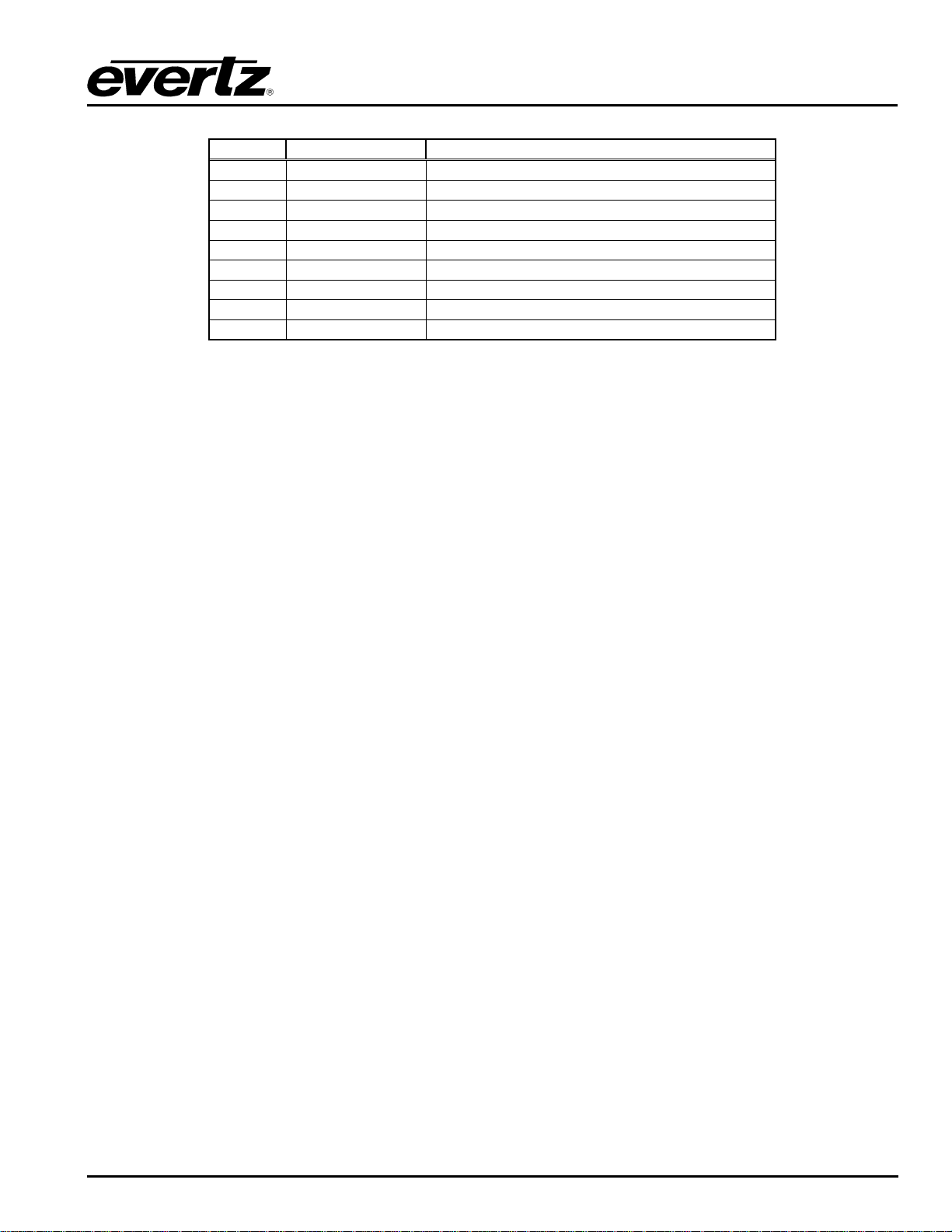
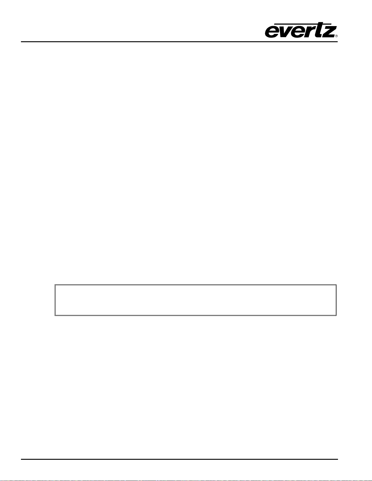
Refer to Table 2-1 and Table 2-2 for the pinout of these cables in RS232 or RS422 modes.
Pin # Name Description
1
2
3
4
5
6
7
8
9
GND Chassis ground
TxD RS-232 Transmit Output
RxD RS-232 Receive Input
Sig Gnd RS-232 Signal Ground
RTS RS-232 RTS Input
CTS RS-232 CTS Output
Table 2-1: Router RS-232 Port Pin Definitions
XRF1 - 2-2 Revision 1.2 INSTALLATION
Page 15
XRF1/XRF1A 16x16 RF Router Manual
Pin # Name Description
1
2
3
4
5
6
7
8
9
2.4. CONTROLLING THE ROUTER USING THE EXTERNAL SERIAL PROTOCOL
The XRF1 router can be controlled from third party M&C systems over the RS232/422 control port, or by
SNMP control over Ethernet. The serial port pinouts are shown in Table 2-1 and Table 2-2 above, and the
protocol supported by the serial port is available by contacting Evertz sales or service departments.
To interface with the XRF1 router via SNMP, contact Evertz technical assistance for the required SNMP
MIB (management information database) information.
GND Chassis ground
Tx- RS-422 Tx-(a) Output
Rx+ RS-422 Rx+(b) Input
GND
GND
Tx+ RS-422 Tx+(b) Output
Rx- RS-422 Rx-(a) Input
GND
Table 2-2: Router RS-422 Port Pin Definitions
INSTALLATION Revision 1.2 XRF1 - 2-3
Page 16

XRF1/XRF1A 16x16 RF Router Manual
This page left intentionally blank
XRF1 - 2-4 Revision 1.2 INSTALLATION
Page 17

XRF1/XRF1A 16x16 RF Router Manual
3. ROUTER CONFIGURATION USING THE CONFIGURATION SERIAL PORT
OR TELNET FACILITY
The XRF1 router frame controller has several settings that can be user configured. Settings such as matrix
size, RF gain mode, crosspoints, network and communication port settings are all accessed through the
frame controller configuration port.
3.1. CONNECTING TO THE FRAME CONTROLLER USING TELNET FACILITY
Using an Ethernet cable, connect the Ethernet port of the XRF1 on the rear panel to an Ethernet switch or
hub (or crossover cable from Ethernet port directly to network card of PC). Open a telnet session on a PC
that is on the same sub-network. The Main Menu will appear with selections as illustrated in section 3.3.
See section 4.5.1 to 4.5.4 for instructions on obtaining the IP address of the router.
3.2. CONNECTING TO THE FRAME CONTROLLER CONFIGURATION SERIAL PORT
Configuration of the router is performed through the configuration serial port labelled ‘UPGRADE1’ on the
breakout cable included with the XRF1. This cable should be connected to the DB15 “SERIAL I/O”
connector on the back of the XRF1. A PC with a terminal emulation program (such as HyperTerminal) is
used to communicate with the frame controller.
The steps for connecting a PC to the frame controller configuration serial port are listed below.
3.2.1. Terminal Program Configuration
Launch a suitable terminal emulation program (such as Microsoft HyperTerminal) and set it to
communicate through the appropriate RS232 serial port on the PC (usually COM1). Configure the serial
port settings of the terminal program as follows:
Baud
Data bits
Parity
Stop bits
Flow Control
3.2.2. Connecting the PC to the Frame Controller
Connect the computer to the cable labeled ‘UPGRADE1’ on the breakout cable connected to the DB15
“SERIAL I/O” female connector on the rear panel of the XRF1.
115200
8
None
1
None
SERIAL PORT Revision 1.2 XRF1 - 3-1
Page 18
XRF1/XRF1A 16x16 RF Router Manual
3.3. CONFIGURATION MAIN MENU
With power applied to the chassis, the frame controller will automatically initiate a boot up procedure,
resulting in the top-level configuration menu being displayed in the terminal program or telnet session.
-----------------------------------------------| Main Menu |
| (XRF1-FC v1.00 b961) |
-----------------------------------------------(1) Network Configuration
(2) Router Configuration
(3) SNMP Setup
(4) Serial Control Port Configuration
(5) Show Card Status
(6) Engineering/Debug
(X) Exit
>
At the prompt, enter the number from the menu list, and press “ENTER”. Remember to save the changes
prior to exiting each configuration menu. Some of the settings require the frame controller to be re-booted
prior to the changes taking effect. This is accomplished by cycling power to the router frame, or by
executing the “Reboot” command from the Engineering/Debug menu.
The (X) option exits the current menu and moves up one menu level.
3.4. NETWORK CONFIGURATION MENU
The network configuration menu displays the existing network settings for the frame controller. To change
any of these values, select the appropriate number from the list, then press “ENTER”, and you will be
prompted for a new value.
NOTE: After changing a network setting, the new setting must be saved prior to
"
exiting configuration mode by selecting “(S) Save and Exit” after each change in
the network configuration.
XRF1 - 3-2 Revision 1.2 SERIAL PORT
Page 19

XRF1/XRF1A 16x16 RF Router Manual
------------------------------------------------
| Network Configuration |
| (XRF1-FC v1.00 b961) |
------------------------------------------------
------------------------------------------------
MAC: 00:02:c5:fe:cb:99
ip address: 192.168.18.50
netmask address: 255.255.192.0
gateway: 0.0.0.0
broadcast address: 192.168.18.255
DHCP enabled: False
------------------------------------------------
(1) Set IP Address
(2) Set Netmask
(3) Set Gateway
(4) Set Broadcast Address
(5) Use DHCP
(S) Save and Exit
(X) Exit
>
It is recommended that the frame controller be connected using a dedicated network in order to maximize
network performance and reliability. In systems where each frame controller is on a dedicated network, the
factory default network settings should be adequate. If the control network for the frame controller is to be
connected to an existing network, the IP address and other network settings will have to be changed so as
to be compatible with the existing network.
3.5. ROUTER CONFIGURATION MENU
The router configuration menu provides access to all configuration settings for the routing matrix. (Select 2
on the main menu item list).
The Router Settings menu provides access to all of the matrix input card settings.
------------------------------------------------
| Router settings |
| (XRF1-FC v1.00 b961) |
------------------------------------------------
(1) Input descriptions
(2) Output descriptions
(3) Salvo descriptions
(4) Salvo Commands
(5) Execute Salvo
(6) Input salvo flag
(7) Output flag
(8) Crosspoints
(9) Passcode
(10) Mode
(11) AGC Output Level
(12) Manual Gain
(13) RF Upper Threshold
(14) RF Lower Threshold
(15) Squelch Threshold
(16) Squelch Enable
SERIAL PORT Revision 1.2 XRF1 - 3-3
Page 20

XRF1/XRF1A 16x16 RF Router Manual
(17) Input Power Level
(18) Output switch delay
(19) LNB power
(20) LNB reset
(21) Misc Fault Status
(22) Input Fault Status
(23) Fan Fault Status
(X) Exit
>
3.5.1. Input / Output Descriptions
The default names (Input 1, Input 2…) may be changed to better correspond to the RF signal to which they
are connected. The input descriptions are used by control system interfaces such as control panels or
VistaLINK
3.5.2. Salvo Descriptions
This menu item allows the salvo descriptions to be altered. A salvo is a preset routing crosspoint map that
can be saved or recalled at any time. Up to 8 salvos can be saved on the XRF1 through the SNMP control
system. The salvos can be executed from any control point (Front panel, serial port or SNMP).
interfaces, thus providing a more familiar control interface for the user.
®
3.5.3. Salvo Commands
This menu item displays the salvos saved on the XRF1 and their corresponding crosspoint maps. Salvos
can only be saved through the VistaLINK
/SNMP software.
®
3.5.4. Execute Salvo
This menu item allows the execution of the 8 salvos that are stored in memory.
3.5.5. Salvo Flag
This indicates the authority access to a salvo. A flag value of 0 indicates the salvo does not contain any
outputs that are locked or protected. A value of 1 indicates the salvo contains an output that is locked and
requires the user or administrator access to execute. A value of 2 indicates the salvo contains an output
that is protected. A value of 3 indicates the salvo contains an output that is locked and protected.
3.5.6. Output Flag
This indicates the authority access to an output. A flag value of 0 indicates the output is not locked or
protected. A value of 1 indicates the output is locked and requires user or administrator access to execute.
A value of 2 indicates the output is protected. A value of 3 indicates the output is locked and protected.
XRF1 - 3-4 Revision 1.2 SERIAL PORT
Page 21

XRF1/XRF1A 16x16 RF Router Manual
3.5.7. Crosspoints
This menu item displays the crosspoints and allows a crosspoint to be set by the user. An input of 0
indicates the output is not connected.
------------------------------------------------
| Crosspoints
| (XRF1-FC v1.00 b961)
|
------------------------------------------------
output input
------ -----
1 <--- 1
2 <--- 2
3 <--- 3
4 <--- 4
5 <---- 5
6 <---- 0
7 <---- 0
8 <--- -0
9 <---- 0
10 <--- 0
11 <--- 0
12 <--- 0
13 <--- 0
14 <--- 0
15 <--- 0
16 <--- 0
------------------------------------------------------------
(1) Set crosspoint
(X) Exit
>
3.5.8. Passcode
This menu item allows the user to view and reset the passwords for the user and the administrator.
3.5.9. Mode
Each input may be set to either manual or automatic gain control (AGC) mode. In manual mode, the gain
through the system on a particular input is fixed, and user specified (0 dB is the default). In automatic gain
control (AGC) mode, the output level on a particular input is fixed, to a user selected target (-20 dBm is the
default). The AGC maintains the output level if the input level is within the range determined by the AGC
output level and the available gain in AGC mode.
3.5.10. AGC Output Level
In AGC mode, each input has a target power output level, as seen by all outputs connected to that input.
The target power default is –20 dBm, but can be set from –20 dBm to –50dBm. The target output level is
maintained, if the input level is within the range determined by the AGC output level and the available gain
in AGC mode.
SERIAL PORT Revision 1.2 XRF1 - 3-5
Page 22

XRF1/XRF1A 16x16 RF Router Manual
3.5.11. Manual Gain Level
In manual gain mode, the gain through the router for all outputs connected to a particular input is fixed.
The default value for all inputs is 0dB, with an adjustable gain range of -9 to +18 dB on the XRF1, or –10 to
+12 dB on the XRF1A.
If a high level input signal (i.e. greater than –10 dBm) is set to high gain, the output level on any connected
inputs will be exceeding design limits. Significant distortion to the RF signal may occur under these
circumstances.
3.5.12. RF Upper Threshold Level / RF Lower Threshold Level
Each input contains an input power monitor that is capable of sending an alarm (SNMP trap) if the input RF
signal power is out of range. These settings allow the user to adjust the acceptable input RF signal power
for upper and lower thresholds. If the RF signal input power goes outside of this range, an alarm is
generated.
3.5.13. Squelch Threshold Power Level
Each input has an input squelch circuit that mutes the input when no signal is present. This command
allows the user to set the power level of the squelch circuit for each input. Below the set input power level,
the input squelch circuit will mute the input.
3.5.14. Squelch Enable
This command allows the squelch function to be enabled or disabled on each input.
3.5.15. Input Power Level
This command generates a list of the current RF signal powers present on each input.
3.5.16. Output Switch Delay
This menu item allows the adjustment of delay between an output switch. The range for this parameter is 0
to 10000 milliseconds in increments of 100.
3.5.17. LNB Power
On XRF1 units with –LNB option, this item allows enable / disable control of the LNB power on the input
connectors of the unit. For each input, the LNB control allows setting the LNB power to OFF or 13V or
17V.
3.5.18. LNB Reset
On XRF1 units with –LNB option, this item allows the reset of the LNB voltage after a short circuit has
occurred. On XRF1A units with the –LNB option, this menu item is not applicable as LNB short circuit
protection is dynamic (i.e. automatically restores when the short/overload is removed)
3.5.19. Misc Fault Status
This item provides information on miscellaneous faults with the router.
XRF1 - 3-6 Revision 1.2 SERIAL PORT
Page 23
XRF1/XRF1A 16x16 RF Router Manual
3.5.20. Input Fault Status
This item indicates any faults on a particular input, such as RF threshold alarms and AGC out of range.
3.5.21. Fan Fault Status
This item indicates any faults with the cooling fans in the chassis.
3.6. SNMP SETUP
The SNMP Setup menu is used to set the SNMP trap IP address used for alarm reporting over SNMP for
VistaLINK
controller flash memory.
"
------------------------------------------------
| SNMP Setup |
| (XRF1-FC v1.00 b961) |
------------------------------------------------
----------------------------------
Trap Destination 1: 192.168.8.3
----------------------------------
(1) Set Trap IP Address
(2) Remove Trap IP Address
(3) Retrieve Trap IP Addresses from flash
(S) Save and Exit
(X) Exit
>
or third party M&C systems. It also displays the current IP address table stored in the frame
®
All changes made within this menu must be saved prior to exiting this menu level
by selecting the “(S) Save and Exit” command. Failure to do so will result in the
changes not taking effect.
3.6.1. Set Trap IP Address
For alarm reporting, the frame controller sends out SNMP traps to a user-specified IP address. This
command allows the user to set all trap destinations on the network. Normally this will be the IP address
of the PC that is running the VistaLINK
system (or both).
3.6.2. Remove Trap IP Address
If a SNMP trap destination address is no longer being used, it should be removed from the Trap IP Address
table to avoid frame controller time out requirements for non-existent IP addresses. This will improve the
efficiency of the frame controller and the control network.
3.6.3. Retrieve Trap IP Addresses from Flash
This command refreshes the frame controller RAM with the IP address table stored in the frame controller
flash memory. This is the IP address table that was stored after the most recent “(S) Save and Exit”
command.
SERIAL PORT Revision 1.2 XRF1 - 3-7
program, or the IP address of the server running the user’s M&C
®
Page 24

XRF1/XRF1A 16x16 RF Router Manual
3.7. SERIAL CONTROL PORT CONFIGURATION
The serial control port menu is used to set the configuration of the serial control port located on the rear of
the frame. It also displays the current settings stored in flash memory. This port is used to control the
routing matrix from external, third party control systems. This menu does not configure the
configuration/upgrade port located on the front edge of the frame controller card.
-----------------------------------------------| Serial Control Port Configuration |
| (XRF1-FC v1.00 b961) |
------------------------------------------------
----------------------------------------------- Baud Rate: 115200
Data Bits: 8
Parity: None
Stop Bits: 2
Standard: RS 232
Protocol: Evertz Router Control
-----------------------------------------------(1) Set baud rate
(2) Set number of data bits
(3) Set parity
(4) Set number of stop bits
(5) Set standard
(6) Set protocol
(X) Exit
>
3.8. ENGINEERING / DEBUG
This menu contains several menu commands that are intended for use only by Evertz engineering staff.
XRF1 - 3-8 Revision 1.2 SERIAL PORT
Page 25
XRF1/XRF1A 16x16 RF Router Manual
4. ROUTER CONFIGURATION USING FRONT PANEL
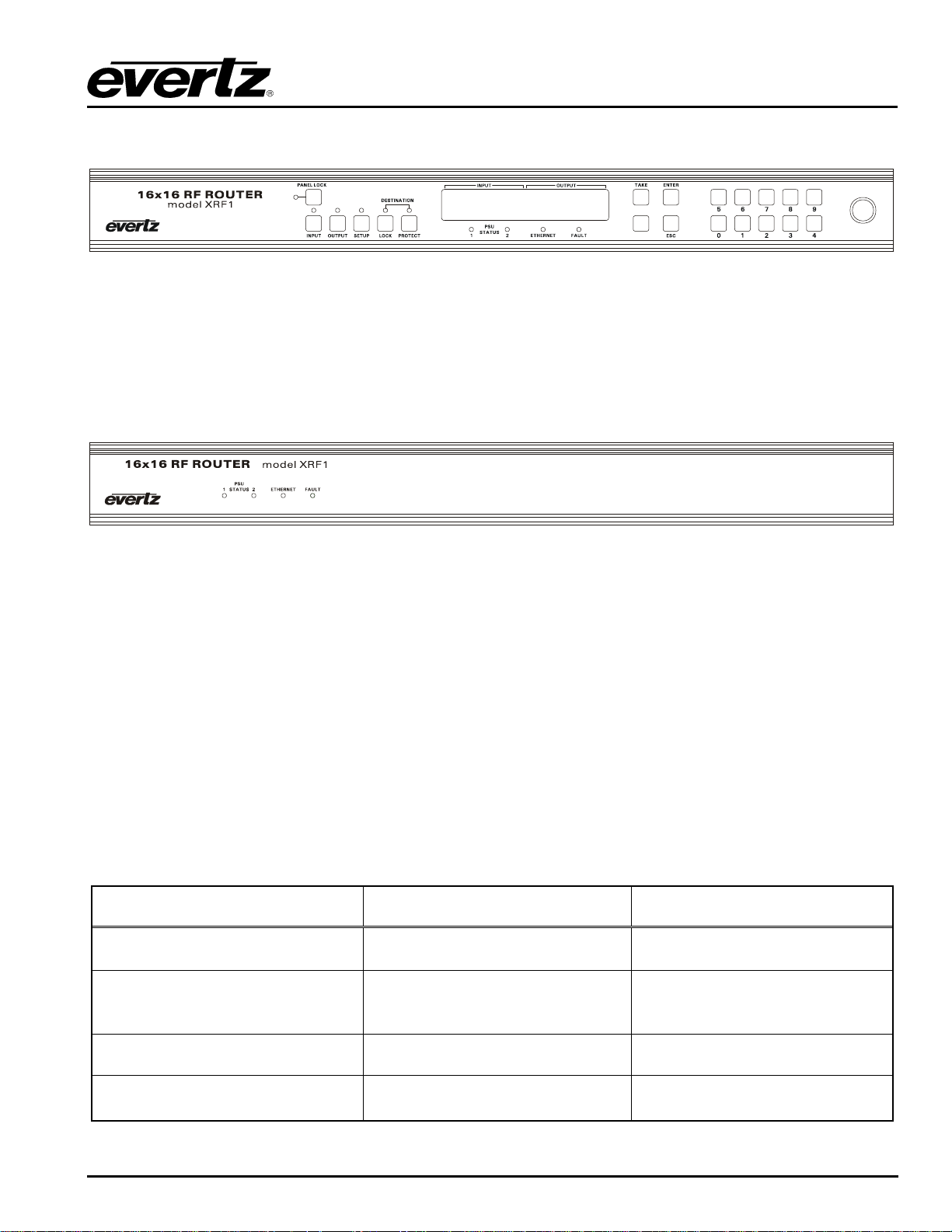
Figure 4-1: Front Panel
The optional XRF1 control panel provides complete crosspoint matrix control, parameter configuration, and
error reporting for the XRF1 16 x 16 RF Router. The control panel is illustrated in Figure 4-1.
The XRF1 RF Router also has a blank front panel ordering option (Figure 4-2), used in multi-chassis
systems as “slave routers” or where system control and configuration are accomplished using a network
control panel, the X-NCP2.
Figure 4-2: Blank Front Panel
4.1. PUSH BUTTON CONTROLS
The XRF1 Control Panel contains 5 modes (described below), which determine the specific operations of
the push buttons and display while performing a specific function. This section describes the operation of
the control panel while in each mode, as well as details the context-sensitive button and display operation.
Refer to Table 4-6 for a description of the function of each button from all modes of operation.
4.1.1. Mode Definitions
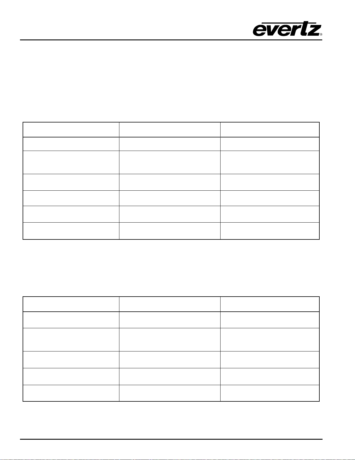
4.1.1.1. Destination Selection Mode
This is the default mode of operation for the XRF1 Control Panel. Destination Selection Mode is initiated
by pressing [OUTPUT]. This mode is used to select matrix destinations (router outputs). The following
table outlines the operations performed by each button while in Destination Selection Mode:
Button/Process
0-9 NUMERIC, SCROLL KNOB
Action While in Destination
Selection Mode
Select destinations Displays selected destination
Resulting Action
[TAKE]
[INPUT], [ENTER]
[MENU]
Performs physical crosspoint change
within router for currently selected
input/output pair
Toggles to Source Selection Mode Displays last manipulated sou rce
Initiates Configuration Menu Mode
Returns to Destination Selection
Mode
Displays passcode prompt, if
enabled
Table 4-1: Button Operations for Destination Selection Mode
FRONT PANEL INTERFACE Revision 1.2 XRF1 - 4-1
Page 26
XRF1/XRF1A 16x16 RF Router Manual
4.1.1.2. Salvo Selection Mode
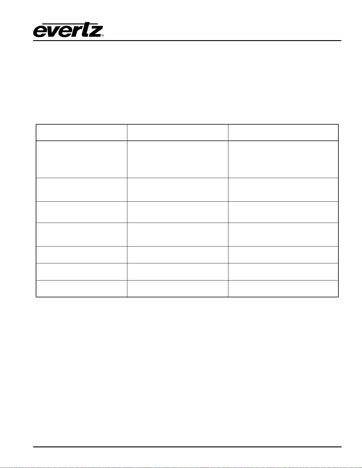
This mode is initiated by pressing the [INPUT] and [OUTPUT] buttons simultaneously. It accesses up to 8
pre-programmed salvos that have been configured using Evertz VistaLINK
A SALVO is a pre-programmed sequence of crosspoint connections that can be constructed using
VistaLINK
and executed from the XRF1 Control Panel. Execution of a salvo is very similar to the
®
execution of an individual crosspoint connection, but the entire list of connections contained in the salvo is
performed. The following table outlines the operations performed by each button while in Salvo Selection
Mode.
Button/Process
Action While in Salvo Selection
Mode
software.
®
Resulting Action
0-9 NUMERIC, SCROLL KNOB
[TAKE]
[OUTPUT]
[INPUT]
[MENU]
30 SECONDS OF INACTIVITY
Select salvos Displays selected salvo
Performs physical group of
crosspoint changes within router for
currently selected salvo
Toggles to Destination Selection
Mode
Toggles to Source Selection Mode Displays last manipulated source
Initiates Configuration Menu Mode
Panel times out
Returns to Salvo Selection Mode
Displays last manipulated
destination
Displays passcode prompt, if
enabled
Returns to Destination Selection
Mode
Table 4-2: Button Operations for Salvo Selection Mode
4.1.1.3. Source Selection Mode
This mode is initiated by pressing [INPUT]. This mode is used to select matrix sources (router inputs). The
following table outlines the operations performed by each button while in Source Selection Mode.
Button/Process
Action While in
Source Selection Mode
Resulting Action
0-9 NUMERIC, SCROLL KNOB
[TAKE]
[INPUT], [ENTER]
[MENU]
30 SECONDS OF INACTIVITY
Select sources Displays selected source
Performs physical crosspoint change
within router for currently selected
input/output pair
Toggles to Destination Selection
Mode
Initiates Configuration Menu Mode
Panel times out Returns to Source Selection Mode
Returns to Destination Selection
Mode
Displays last manipulated
destination
Displays passcode prompt, if
enabled
Table 4-3: Button Operations for Source Selection Mode
XRF1 - 4-2 Revision 1.2 FRONT PANEL INTERFACE
Page 27
XRF1/XRF1A 16x16 RF Router Manual
4.1.1.4. Configuration Menu Mode
This mode accesses the router Configuration Menu. The Configuration Menu is passcode protected only if
the user has enabled this feature through VistaLINK
Administrator-level passcode. Entry of the proper passcode accesses router control and configuration
parameters. If passcode protection has not been enabled, pressing [MENU] takes the user directly to
Level 1 of the Configuration Menu. Selecting the “exit” option from menu Level 2 terminates Configuration
Menu Mode.
The following table outlines the operations performed by each button while in Configuration Menu Mode.
Button/Process
[ESC]
Action While in Configuration
Menu Mode
Moves up one menu level. At the
top level of the configuration menu,
it will exit this mode and return to
Destination select menu mode
(default)
. If enabled, pressing [MENU] prompts the user for an
®
Resulting Action
Displays higher menu level or exits
menu mode to default
0-9 NUMERIC
SCROLL KNOB
[INPUT] and/or [OUTPUT]
[ENTER]
[MENU]
30 SECONDS OF INACTIVITY
Selects source channel Displays selected source channel
Navigates menu options Displays selected option
Exits Configuration Menu Mode,
and enters Source, Destination, or
Salvo Selection Mode
Finalizes option selection and
moves down one menu level
Returns user to Menu Level 1 (Input
Channel Selection)
Panel times out Returns to Destination Selection Mode
Displays last manipulated source,
destination, or salvo
Displays first option in subsequent
menu level
Displays “SELECT INPUT”
Table 4-4: Button Operations for Configuration Menu Mode
4.1.1.5. Configuration Set Mode
This mode defines the operation of the XRF1 while in the lowest menu level, where parameters such as
gain and output levels can be set from within the Configuration Menu. The following table outlines the
operations performed by each button while in Configuration Set Mode.
FRONT PANEL INTERFACE Revision 1.2 XRF1 - 4-3
Page 28
XRF1/XRF1A 16x16 RF Router Manual
Button/Process
[ESC]
0-9 NUMERIC, SCROLL KNOB
[INPUT] and/or [OUTPUT]
[ENTER]
[MENU]
30 SECONDS OF INACTIVITY
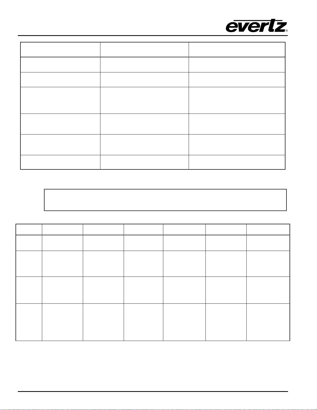
Table 4-5: Button Operations for Configuration Set Mode
Action While in
Configuration Set Mode
Moves up one full menu level
Sets configuration parameter
Resulting Action
Displays first menu option on selected
level
Displays selected configuration
parameter
Exits Configuration Menu Mode,
without making changes, and enters
Source, Destination, or Salvo
Displays last manipulated source,
destination, or salvo
Selection Mode
Saves parameter changes and
moves up one menu level
Displays “CHANGES SAVED” for 1
second, then shows first option in upper
menu level
Returns user to Menu Level 1 (Input
Channel Selection) without making
Displays “SELECT INPUT”
changes
Panel times out Returns to Destination Selection Mode
Pressing [ENTER] is the only way to make physical changes to the router
"
configuration parameters.
BUTTON
PANEL
LOCK
INPUT
OUTPUT No operation
MENU
Destination
Selection Mode
Disables all buttons
(except Panel Lock)
Exits Destination
Selection Mode and
enters Source
Selection Mode
Enters
Configuration Menu
Mode and prompts
for 4-digit
passcode, if one
has been set
Salvo Selection
Mode
Disables all buttons
(except Panel Lock)
Exits Salvo
Selection Mode and
enters Source
Selection Mode
Terminates Salvo
Selection Mode and
toggles to
Destination
Selection Mode
Enters
Configuration Menu
Mode and prompts
for 4-digit
passcode, if one
has been set
Source
Selection Mode
Disables all
buttons (except
Panel Lock)
No operation
Terminates Source
Selection Mode
and toggles to
Destination
Selection Mode
Enters
Configuration
Menu Mode and
prompts for 4-digit
passcode, if one
has been set
Configuration
Menu Mode
Disables all buttons
(except Panel Lock)
Exits Configuration
Menu and enters
Source Selection
Mode
Exits Configuration
Menu and enters
Destination
Selection Mode
Returns user to
Level 1 of the
Configuration Menu
and displays
“SELECT INPUT”
Configuration
Set Mode
Disables all buttons
(except Panel Lock)
Exits Configuration
Menu without
making changes
and enters Source
Selection Mode
Exits Configuration
Menu without
saving changes and
enters Destination
Selection Mode
Returns user to
Level 1 of the
Configuration Menu
without making
changes and
displays “SELECT
INPUT”
NOTES
Toggles between
Panel Lock enabled
and disabled.
Enters Source
Selection Mode
Used with [OUTPUT]
to access Salvo
Selection Mode
Enters Destination
Selection Mode
Used with [INPUT] to
access Salvo
Selection Mode
If passcode
protection is enabled
using VL software,
pressing [MENU]
prompts for
Administrator
passcode to access
Configuration Menu
XRF1 - 4-4 Revision 1.2 FRONT PANEL INTERFACE
Page 29
LOCK
PROTECT
TAKE
ENTER
0 – 9
NUMERIC
Enables “locking” of
the current
destination from
manipulation by
unauthorized users,
denoted by the
LOCK LED blinking
at 2Hz
Enables a “protect”
on the current
destination,
denoted by the
PROTECT LED
blinking at 2Hz
Performs router
crosspoint change
for input/output
currently displayed
Finalizes
destination
selection and
toggles to Source
Selection Mode
Manual entry of
specific destination
desired
If LOCK LED is
blinking when
displaying current
salvo, this indicates
the salvo contains
an output that is
locked.
If PROTECT LED is
blinking when
displaying current
salvo, this indicates
the salvo contains
an output that is
protected.
Performs router
crosspoint change
for the salvo
currently displayed
Finalizes manual
keypad entry of
salvo selection and
displays selected
salvo name
Manual entry of
specific salvo
desired
XRF1/XRF1A 16x16 RF Router Manual
No operation No operation No operation
No operation No operation No operation
Performs router
crosspoint change
for input/output
currently displayed
Finalizes source
selection and
toggles to
Destination
Selection Mode
Manual entry of
specific source
desired
No operation No operation
Enters value
Finalizes menu
selections and
moves to
subsequent menu
level
Manual entry of
specific source
(input channel)
desired
selected and
displays
“CHANGES
SAVED” message
for 1 second;
moves user up one
menu level
Manual entry for
setting parameters,
such as gain;
changes to nearest
value in MIB upon
pressing [ENTER]
If passcode
protection is enabled
through VL, 2 levels
of passcode
protection are
supported to
lock/unlock
destinations/salvos:
- multiple operator
codes
-one administrator
code
Toggles between
Protect enabled and
disabled for currently
selected destination
or salvo
Performs crosspoint
connection of
displayed
Source/Destination
pair, or displayed
Salvo
Must be used before
exiting Configuration
Set Mode for
changes to take
effect (this action
displays a
“CHANGES SAVED”
confirmation
message)
0 – 9 NUMERIC
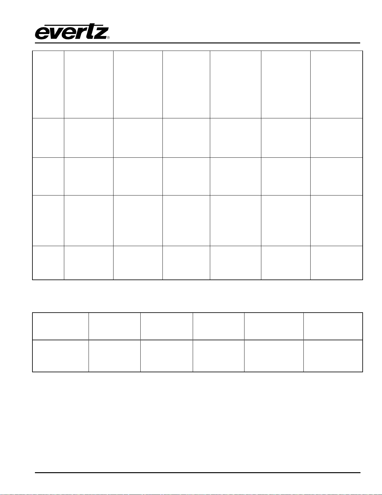
Table 4-6: Overview of Push-Button Operations
4.2. SCROLL KNOB
Scroll Knob
Manipulation
Rotate
Function within
Destination
Selection Mode
Navigates
destinations
available on the
router network
Function within
Salvo Selection
Mode
Navigates
available salvos
programmed
from VistaLINK
Function within
Source
Selection Mode
Navigates
sources
available on the
router network
®
Function within
Configuration
Menu Mode
Navigates menu
choices on the
current menu level
Function within
Configuration Set
Mode
Allows user to set
desired parameter,
such as gain, in 1
Db increments
4.3. 16-CHARACTER DISPLAY SCREEN
When equipped with a local control panel, the 16-character display screen of the XRF1 Control Panel is
responsible for visually informing the user of a variety of conditions, including source, destination, and
salvo name display, passcode prompting, confirmation messaging, and error reporting.
FRONT PANEL INTERFACE Revision 1.2 XRF1 - 4-5
Page 30
XRF1/XRF1A 16x16 RF Router Manual
4.3.1. Display Function within Modes of Operation
Through Monitoring and Control software, such as Evertz’ VistaLINK
, each source, destination and salvo
®
can be assigned up to a 16-character name. The XRF1 display screen functions in a “split-display view” or
“full-display view,” depending on if the unit is sitting idle, actively scrolling through sources/destinations, or
displaying a level of the Configuration Menu. When entering selections numerically, using the 0-9 keypad,
the XRF1 display will automatically function in “numeric entry display,” described below.
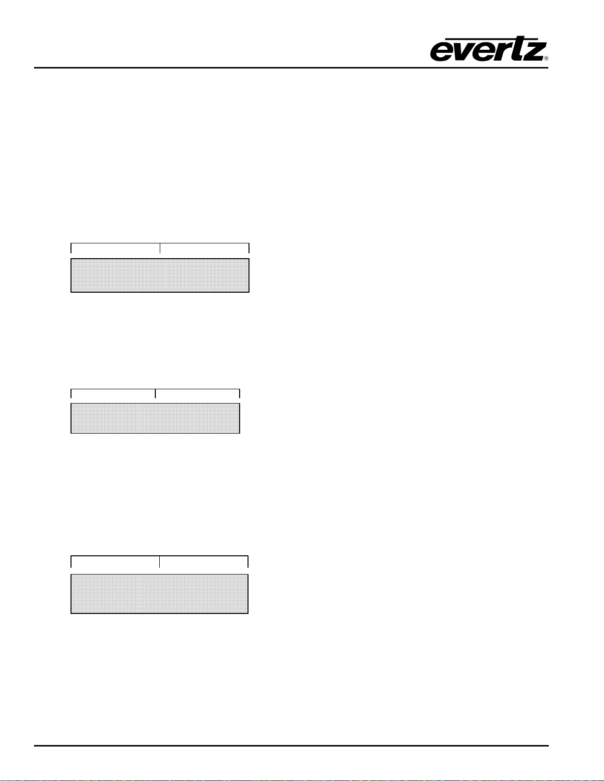
SPLIT-DISPLAY VIEW: The display screen utilizes this view only from Source Selection Mode or
Destination Selection Mode. The screen functions as a “split display” when it is idle, or after 1 second of
inactivity. In split-display view, the screen shows the 7 rightmost characters of the source name on the lefthand side of the display and the 7 rightmost characters of the destination name on the right-hand side.
STAR _ 12 _ _ _ IRD_16
FULL-DISPLAY VIEW: The display screen can utilize this view from all modes of operation. The screen
functions as a full 16-character display when a user is actively scrolling in Source or Destination Selection
Modes, as well as when displaying a salvo name, or any level of the Configuration Menu. In full-display
view, the screen shows all 16 characters of the source/destination/salvo name, or the configuration menu
option.
TELSTAR 12
NUMERIC ENTRY VIEW: The display screen can utilize this view from all modes of operation. The
screen functions only to display the numeric characters being entered when making selections using the 09 keypad. When a number is manually entered from the keypad, only the number is displayed, right
justified; the rest of the screen is blank. When the user has entered the full 1 or 2 digit number, they can
finalize their selection by pressing [ENTER] and move to the subsequent selection display. If the user fails
to finalize their selection by pressing [ENTER], numeric entry view will timeout after 2 seconds of inactivity
and return to the previous display. Pressing any other button from numeric entry view will exit the view
without finalizing a selection.
_ _ _ _ _ _ _ _ _ _ _ _ 21
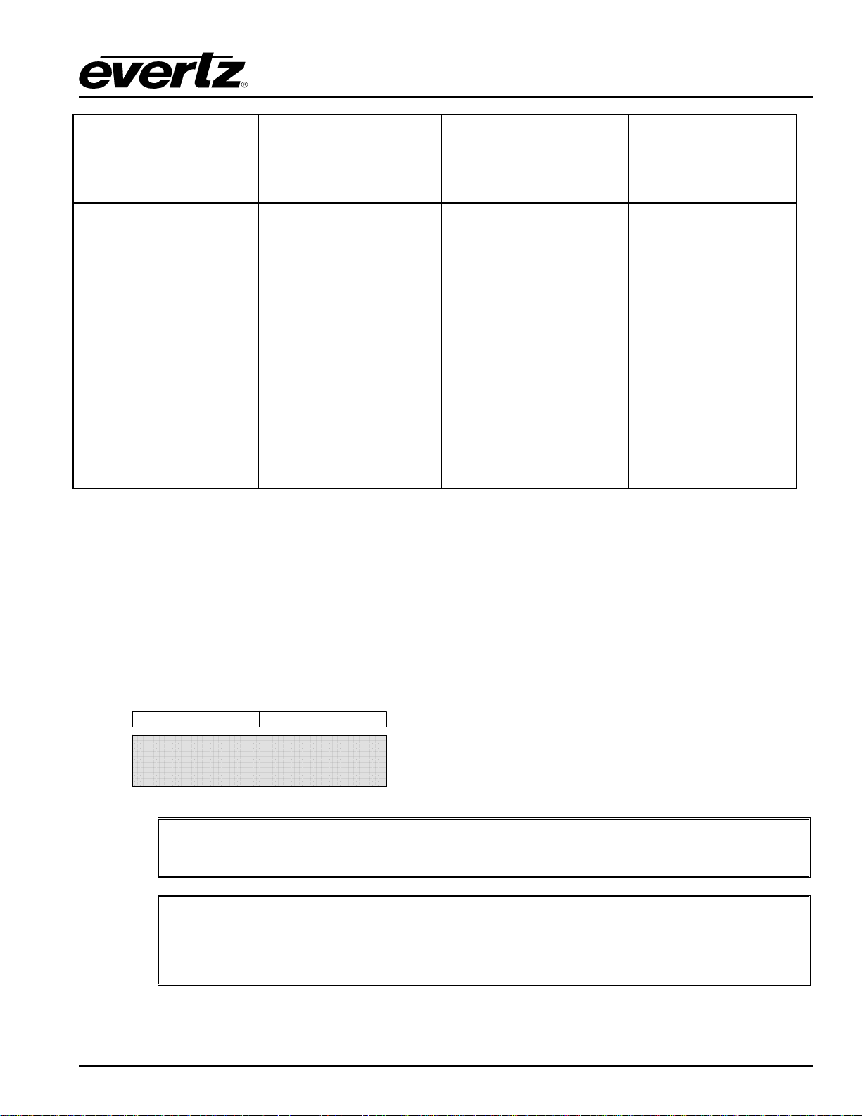
Table 4-7 defines the function of the display more clearly for each mode of operation and the action being
performed.
XRF1 - 4-6 Revision 1.2 FRONT PANEL INTERFACE
Page 31
Content Display within
Destination Selection
Mode
WHILE IDLE, or AFTER 1
SECOND OF INACTIVITY:
split-display view of the
selected destination and its
current source
WHILE ACTIVELY
SCROLLING THROUGH
DESTINATIONS:
full-display view of 16character destination name
WHILE ENTERING A 0-9
NUMERIC SELECTION
FROM THE KEYPAD:
numeric entry view
Content Display within
Salvo Selection Mode
WHILE IDLE, WHILE
ACTIVELY SCROLLING
THROUGH SALVOS, and
AFTER 1 SECOND OF
INACTIVITY:
full-display view of 16character salvo name
WHILE ENTERING A 0-9
NUMERIC SELECTION
FROM THE KEYPAD:
numeric entry view
XRF1/XRF1A 16x16 RF Router Manual
Content Display
Content Display within
Source Selection Mode
WHILE IDLE, or AFTER 1
SECOND OF INACTIVITY:
split-display view of the
selected source and its
current destination
WHILE ACTIVELY
SCROLLING THROUGH
SOURCES:
full-display view of 16character source name
WHILE ENTERING A 0-9
NUMERIC SELECTION
FROM THE KEYPAD:
numeric entry view
within Configuration
Menu Mode and
Configuration Set
Mode
WHILE NAVIGATING
THE CONFIGURATION
MENU: full-display view
of the current menu
option or parameter
being set
WHILE ENTERING A 09 NUMERIC
SELECTION FROM THE
KEYPAD: numeric entry
view
Table 4-7: Description of Display Function within XRF1 Modes of Operation
4.3.1.1. Name Display when Control Panel is Idle
The display screen of the XRF1 Control Panel is designed to show users the full 16-character name
assigned to each source and destination, as well as the current pairing status for each source/destination.
While in Source Selection Mode or Destination Selection Mode, the screen typically functions in splitdisplay view.
A possible name for one user source/destination pairing may be: TELSTAR 12 and IRD 16. The
Destination Selection Mode display of that pairing while idle would look like the following example:
STAR _ 12 _ _ _ IRD_16
The “_” underscores are not visible, but are included in the manual for a clearer
"
explanation.
The full assigned name of the source in this example is “TELSTAR 12,” but when sitting
idle, only the last 7 alphanumerical characters of the name are shown. Therefore, if a
"
name is less than 7 characters long, such as “IRD 16,” it will be displayed as “IRD 16,” not
as 7 empty spaces.
FRONT PANEL INTERFACE Revision 1.2 XRF1 - 4-7
Page 32
XRF1/XRF1A 16x16 RF Router Manual
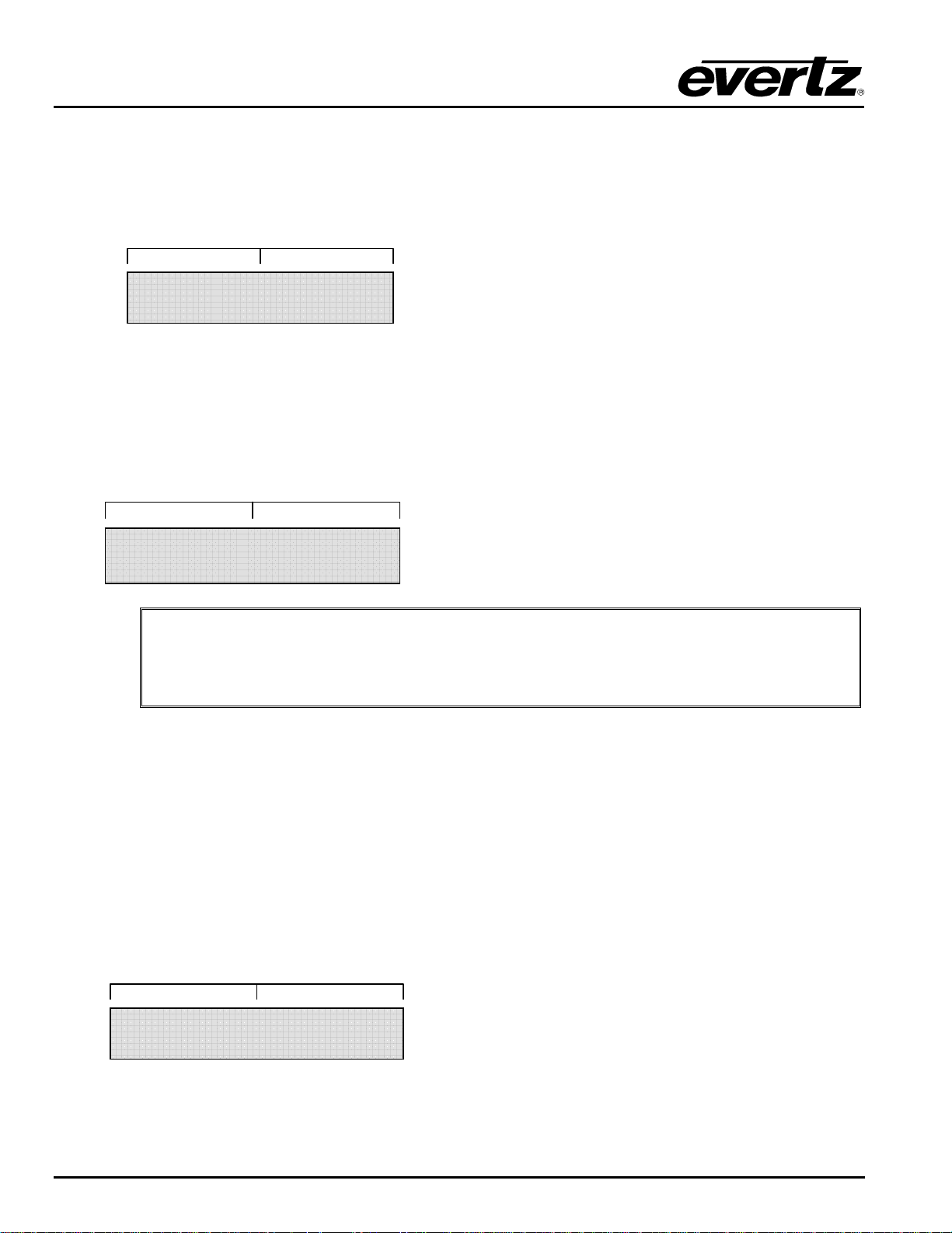
4.3.1.2. Name Display when Actively Scrolling
While actively scrolling in Source Selection or Destination Selection Modes, the screen functions in fulldisplay view, showing all 16 characters of the source or destination name.
For example, while scrolling through destinations, the display will show the destination “IRD 16” as:
4.3.1.3. Name Display after 1 Second of Inactivity
In Source Selection or Destination Selection Mode, the user stops scrolling when they reach a desired
channel. The display will timeout after 1 second of inactivity and return to split-display view, providing
status of this destination and the source currently associated with it.
The screen would then look like this:
IRD_16_ _ _ _ _ _ _ _ _
STAR _ 12 _ _ _ IRD _ 16
The full assigned name of the source in this example is “TELSTAR 12,” but after 1 second
of inactivity, only the last 7 alphanumerical characters of the name are shown.
"
4.3.1.4. Name Display when in Salvo Selection Mode
Salvos may be assigned up to a 16-character name through VistaLINK
names are assigned. If no name is assigned, default naming of salvos will be “SALVO 1,” “SALVO 2,” and
so on, to 8. Examples of salvo names are “ALL CALL SOURCE 5,” which would connect input channel 5
to all destinations, or “DIAGONAL,” which would connect source 1 to destination 1; source 2 to destination
2, and so on.
There is no difference in the display of salvo names while actively scrolling vs. periods of inactivity, as
salvo names are always shown in full-display view, containing all 16 characters. If the user stops on a
salvo name while scrolling, the 1-second timeout does not occur. The display continues to function in fulldisplay view. For example, the display for a salvo named “ALL CALL SOURCE 5” will always look like
this:
To execute a salvo, the user scrolls to the desired salvo name in Salvo Selection Mode, and presses
[TAKE].
Therefore, if a name is less than 7 characters long, such as “IRD 16,” it will be displayed
as “IRD 16,” not as 7 empty spaces.
, just as source and destination
®
ALL _ CALL _ SOURCE 5
XRF1 - 4-8 Revision 1.2 FRONT PANEL INTERFACE
Page 33
XRF1/XRF1A 16x16 RF Router Manual
4.3.1.5. Name Display when in Configuration Menu Mode
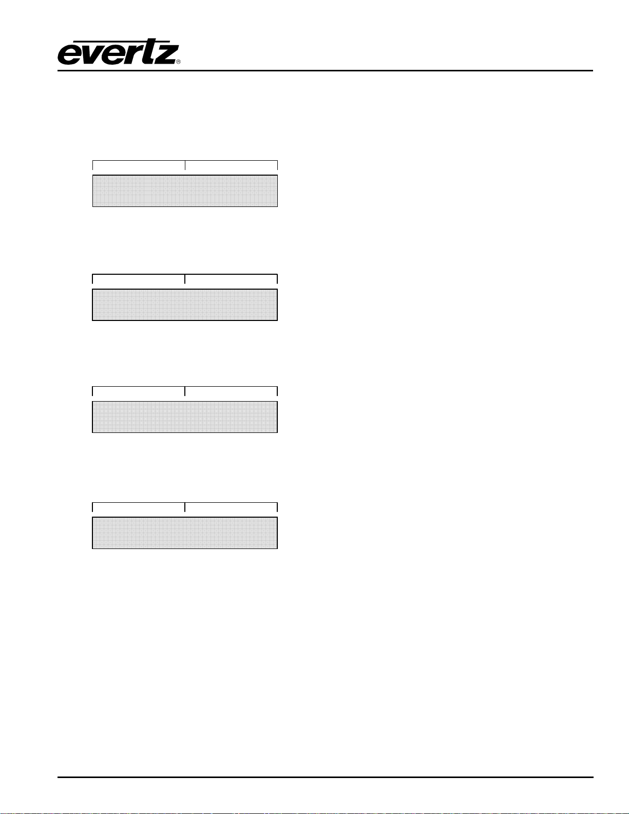
When a user presses [MENU], they are prompted for a passcode (if enabled). Refer to section 4.3.2 of this
document for further explanation of this passcode protection. After the user passes the code protection
feature of the Configuration Menu, they are prompted to select the input channel they are wishing to
access parameters for. The display prompt will look like the following example:
Entering a number from the 0-9 keypad takes the user directly to that input channel. For example, if the
source named “TELSTAR 12” is on input channel 5, pressing #5 on the keypad would result in the following
display:
From the “SELECT INPUT” prompt, one rotation of the scroll knob clockwise or pressing the down arrow
displays input channel 1. If the source on input channel 1 has been named “TELSTAR 20,” the display
would show the following:
From the “SELECT INPUT” prompt, one rotation of the scroll knob counter-clockwise or pressing the up
arrow displays input channel 16 (or 32). If the source on input channel 16 (or 32) has been named
“TELSTAR 15,” the display would show the following:
SELECT INPUT
5 TELSTAR 12
1 TELSTAR 20
16 TELSTAR 15
4.3.2. Display Function in Passcode Prompting
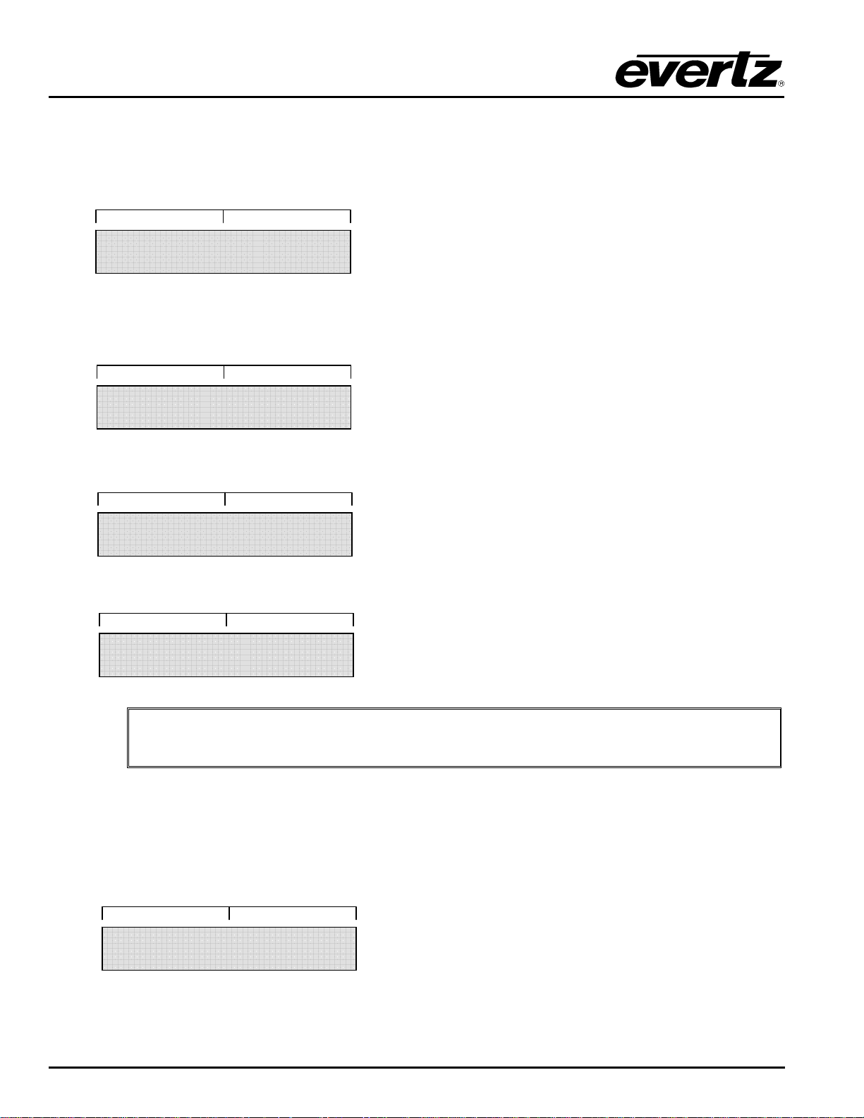
The XRF1 Control Panel has 3 passcode-protected features: the Configuration Menu, Destination Lock and
Salvo Lock. When passcode protection has been enabled, through VistaLINK
, for any of these functions,
®
the display screen visually prompts the user for the passcode necessary to access these features. If no
passcode protection has been setup through VistaLINK
, no prompting will occur and the user will be free
®
to directly access any of these features.
FRONT PANEL INTERFACE Revision 1.2 XRF1 - 4-9
Page 34
XRF1/XRF1A 16x16 RF Router Manual
4.3.2.1. Configuration Menu Passcode Access
The Configuration Menu may be pro tected by 1 system-wide, administrator-level passcode, when enabled
through VistaLINK
Destination or Salvo Selection Mode, and the display now prompts the user for the passcode:
MENU CODE?
The user enters the passcode using the 0-9 numeric buttons and the first choice of Level 2 of the
Configuration Menu is displayed in full-display view:
If the user enters the incorrect passcode, the screen will display a 2-second message that will look like this:
After 2 seconds, the screen will once again display the passcode prompt, as shown below:
1. INPUT LEVEL
INVALID CODE
MENU CODE?
. When passcode protection is enabled, the user presses [MENU] from Source
®
"
Refer to Figure 5-3 for the operational flow for accessing the Configuration Menu.
4.3.2.2. Destination Lock Passcode Access
The destination “lock” function may be passcode protected, when enabled through VistaLINK
administrator may assign both “operator” and “administrator” passcode types. When passcode protection
is enabled, the user presses [LOCK] from Destination Selection Mode, and the display now prompts the
user for the passcode:
LOCK CODE?
XRF1 - 4-10 Revision 1.2 FRONT PANEL INTERFACE
. A system
®
Page 35
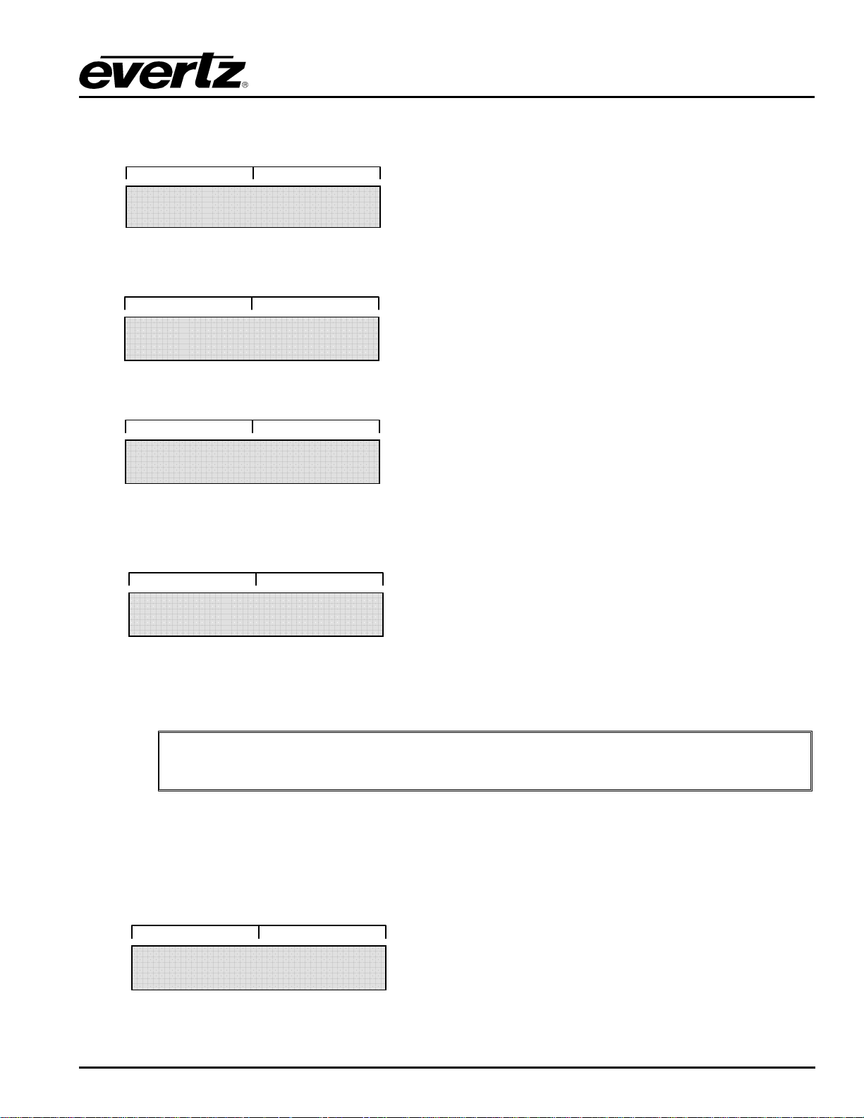
XRF1/XRF1A 16x16 RF Router Manual
The user now enters the passcode using the 0-9 numeric buttons and the control panel returns to
Destination Selection Mode:
If the user enters the incorrect passcode, the screen will display a 2-second message that will look like this:
After 2 seconds, the screen will once again display the passcode prompt:
If a user presses [TAKE] for a crosspoint pair that includes a “locked” destination, the display will prompt for
the passcode again:
If the user enters a valid passcode, the display will return to provide the status of the current crosspoint pair
and a successful “take” can then be executed.
INVALID CODE
LOCK CODE?
UNLOCK CODE?
Refer to Figure 5-4 for the operational flow for accessing the destination Lock
"
4.3.3. Display Function in Confirmation Messaging
The XRF1 Control Panel has two possible confirmation messages.
From Source Selection Mode, Destination Selection Mode, or Salvo Selection Mode, a successful “take”
will result in the following display for 2 seconds:
FRONT PANEL INTERFACE Revision 1.2 XRF1 - 4-11
feature.
TAKE SUCCESSFUL
Page 36
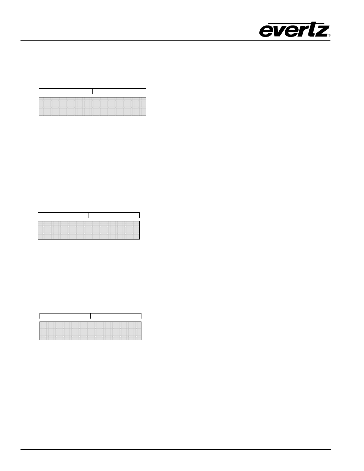
XRF1/XRF1A 16x16 RF Router Manual
After 2 seconds, the display will return to the previous mode, defining the status of the crosspoint pair or
salvo just “taken.”
From the Configuration Set Mode, pressing [ENTER] or depressing the scroll knob after changing a
configuration parameter will result in the following display for 2 seconds:
After 2 seconds, the display will show the previous menu level. Pressing [ENTER], depressing the scroll
knob, or pressing the down arrow will take the user back into the parameter to be changed.
4.3.4. Display Function in Error Reporting
A “fault” status for the XRF1 can occur in two forms. The panel will detect a “fault” when it experiences a
loss of communication with any device on the system network. A “fault” can also develop in the event that
a user attempts to manipulate router configurations beyond acceptable parameters. When the XRF1 panel
detects a fault status, it will display an “ERROR” message for 2 seconds.
The screen would look like this:
After the “ERROR” message has been displayed for 2 seconds, the display will return to the function it was
performing prior to the error occurrence.
CHANGES SAVED
ERROR
4.3.5. Display Function in “Panel Locked” Status
When the “Panel Lock” function has been enabled, (refer to Table 4-6 and Table 4-8) the display will flash
a 2-second message when any buttons or knobs are manipulated. The screen will look like this:
4.4. STATUS INDICATOR LEDS
The XRF1 Control Panel is equipped with 10 LED indicators and the blank front panel that has 4 LEDs for
status indication. The function of each is outlined in Table 4-8.
PANEL LOCKED
XRF1 - 4-12 Revision 1.2 FRONT PANEL INTERFACE
Page 37
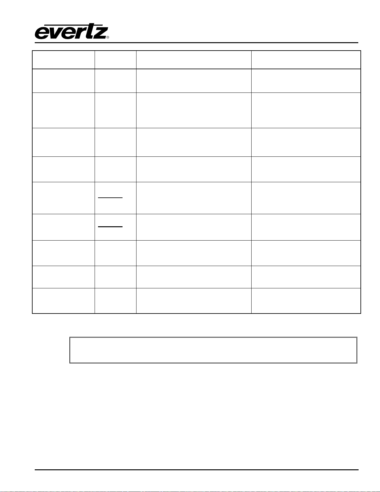
XRF1/XRF1A 16x16 RF Router Manual
INDICATOR NAME
PANEL LOCK LED
INPUT LED
OUTPUT LED
MENU LED
LOCK LED
PROTECT LED
COLOUR
WHEN LIT
Green
Green
Green
Green
Configuration Menu Mode initiated
Blinking
Green
Blinking
Green
LIT INDICATION DARK INDICATION
Panel controls are fully locked out of
operation
Source Selection Mode initiated
When lit with the OUTPUT LED,
indicates Salvo Selection Mode
initiated
Destination Selection Mode initiated
When lit with the INPUT LED, indicates
Salvo Selection Mode initiated
Selected destination has been ‘locked’
out of availability from unauthorized
users or selected salvo contains a
‘locked’ destination.
Selected destination has been flagged
as ‘protected’ to users or selected
salvo contains a ‘protected’ destination.
Panel controls are available for
manipulation
Panel not in Source Selection Mode
or Salvo Selection Mode
Panel not in Destination Selection
Mode or Salvo Selection Mode
Panel not in Configuration Menu
Mode
Selected destination is not locked or
selected salvo does not contain
locked destination.
Selected destination is not protected
or selected salvo does not contain
protected destination.
PSU STATUS
1 & 2 LED’s
ETHERNET LED
FAULT LED
Green
Green
Red
Power supply unit(s) are functioning
properly
Ethernet network communication is
functioning properly
Corresponds to any trap breech within
the router configuration
Power supply is not in use, or is in
“Fault” status
Ethernet network communication has
been lost and is in “Fault” status
Router hardware is functioning within
acceptable parameters
Table 4-8: Description of Status Indicator LED Functions
The “LOCK” and “PROTECT” LED’s will blink at 2 Hz.
"
4.5. CONFIGURATION MENU OVERVIEW
4.5.1. Configuration Menu Function and Display
The Configuration Menu allows the user to access all configuration parameters for the XRF1 RF Router via
the front face Control Panel. The Configuration Menu is accessed via the [MENU] button, and the user has
the option to enable passcode protection for this menu. (Refer to section 4.3.1.5 for further description of
the Configuration Menu passcode protection). Figure 4-3 defines the Configuration Menu structure, per
input channel.
FRONT PANEL INTERFACE Revision 1.2 XRF1 - 4-13
Page 38
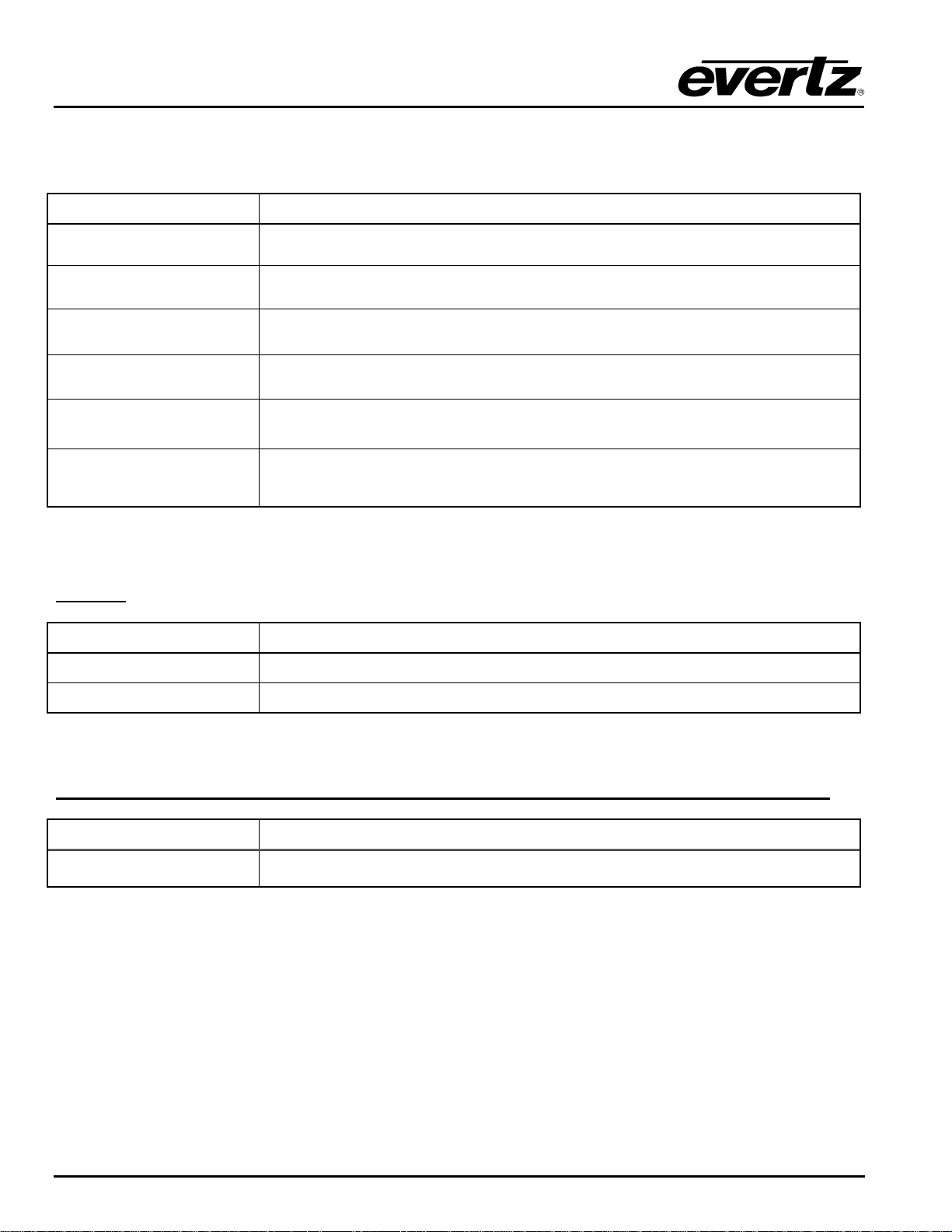
XRF1/XRF1A 16x16 RF Router Manual
4.5.2. Configuration Main Menu Options and Parameters
The following options are available at the top level of the configuration menu:
PARAMETER DESCRIPTION
Configure Input
Configure Output
Lock Idle Panel
IP Address
Firmware Version
Allows configuration of all inputs (see section 5.2 for more info).
Allows configuration of all outputs.
Allows locking of panel after inactivity for 5 minutes.
Panel is unlocked by pressing the [PANEL LOCK] key.
Displays the router IP address.
Displays the firmware version.
Allows a ‘warm’ reboot of the router processor.
Reboot
Configuration settings are maintained during a reboot.
Table 4-9: Configuration Menu Options
4.5.3. CONFIGURE OUTPUT Menu Options and Parameters
LEVEL1:
PARAMETER DESCRIPTION
All Outputs
Allows configuration of all outputs.
Channel 1 to 16
Output channel selection.
Table 4-10: Configure Output Menu Options
LEVEL 2: (options available for ALL INPUTS or individual input channel as selected in Level 1)
PARAMETER DESCRIPTION
Output Delay
Accesses output delay setting, set from 0 to 5000ms in 100ms increments.
Table 4-11: Options Available for ALL INPUTS or Individual Input Channel
as Selected in Configure Output Menu Level 1
XRF1 - 4-14 Revision 1.2 FRONT PANEL INTERFACE
Page 39
XRF1/XRF1A 16x16 RF Router Manual
4.5.4. CONFIGURE INPUT Menu Options and Parameters
LEVEL1:
PARAMETER DESCRIPTION
All Inputs
Channel 1 to 16
Allows configuration of all inputs
Input channel selection
Table 4-12: Configure Input Menu Options
LEVEL 2: (options available for ALL INPUTS or individual input channel as selected in Level 1)
PARAMETER DESCRIPTION
Input Level
Output Level
Gain Mode
Gain
Squelch
RF Threshold
Statuses current input level -5dBm to -70dBm
Accesses output level setting -20dBm to -50dBm in increments of 1dBm in
AGC MODE only.
Accesses AGC MODE and MANUAL GAIN MODE options.
Accesses manual gain (+18 to –6dB on XRF1, or +12 to –10dB on XRF1A, in
1dB steps) in MANUAL. GAIN MODE only
Accesses ON or OFF options.
Accesses UPPER, LOWER, and SQUELCH threshold settings.
LNB Power (-LNB
option only)
LNB Reset (-LNB
option only)
Accesses +13V / +18V / OFF settings for LNB.
Accesses reset of LNB power after a short circuit detect.
Table 4-13: Options Available for ALL INPUTS or Individual Input Channel
as Selected in Configure Input Menu Level 1
LEVEL 3 ( RF THRESHOLD MENU ITEMS ):
PARAMETER DESCRIPTION
Upper
Lower
Squelch
1dBm increments, from –5dBm to –30dBm
1dBm increments, from - 70dBm to –31dBm
1dBm increments, from –70dBm to –50dBm
Table 4-14: RF Threshold Menu Options
FRONT PANEL INTERFACE Revision 1.2 XRF1 - 4-15
Page 40
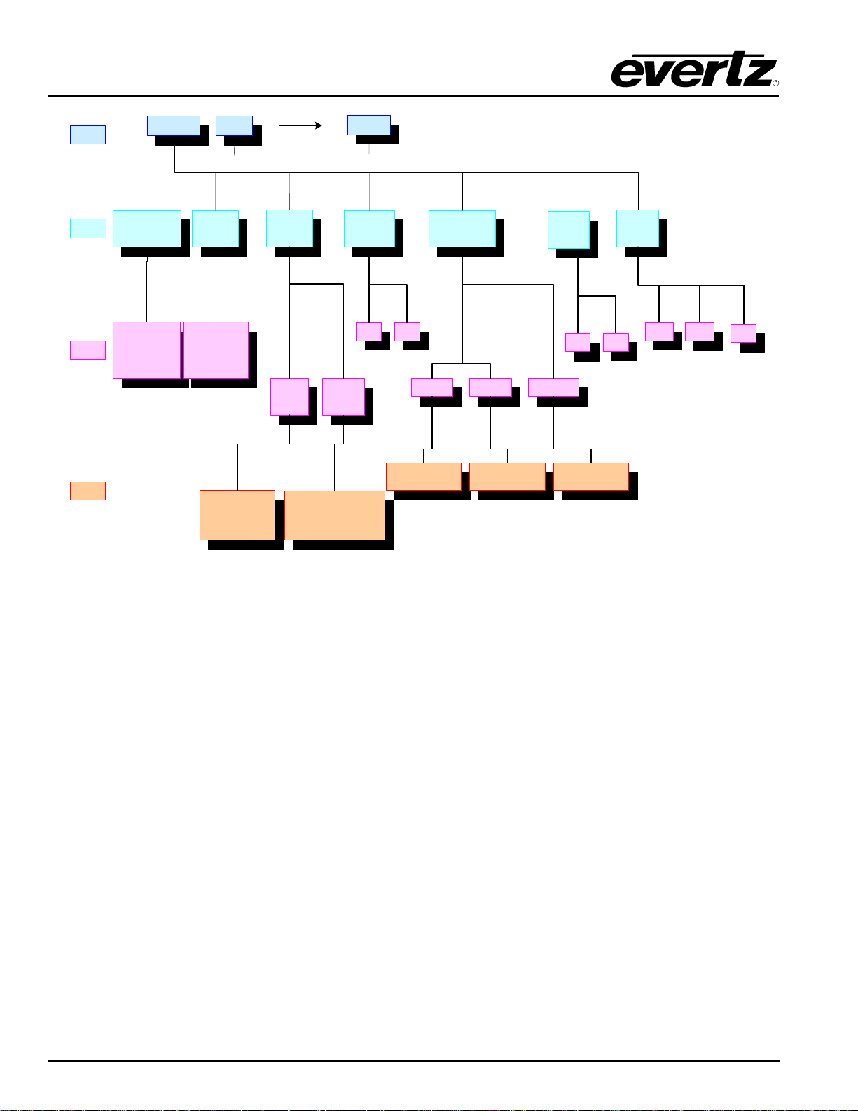
XRF1/XRF1A 16x16 RF Router Manual
LEVEL 1
LEVEL 2
LEVEL 3
LEVEL 4
ALL INPUTS INPU T 1
INPUT LEVEL
( ind. ch )
Statuses current
Input Level
-5 to -70 dBm
OUTPUT
LEVEL
Statuses current
Output Level
-20 to -50 dBm
SETS OUTPUT LEVEL
Displays -20dBm (allows
parameter setting in 1dBm
increments to -50dBm)
INPU T 16
….. …..
GAIN
MODE
AGC
MODE
SETS OUTPUT VS. INPUT GAIN
Displays 0dB (allows parameter
setting in 1dB increments from -
MANUAL
GAIN
MODE
DIFFERENCE
15dB to -16dB)
SQUELCH
RF
THRESHHOLD
OFFON
UPPER LO WER SQUELCH
Displays -5dBm (allows
parameter setting in 1dBm
increments to -30dBm)
Displays -70dBm (allows
parameter setting in 1dBm
increme n ts to -3 1dBm )
LNB
RESET
NO
YES
Displays -70dBm (allows
parameter setting in 1dBm
increments to -50dBm)
LNB
POWER
+13V
+18V
OFF
Figure 4-3: Configuration Menus Structure per Input Channel
XRF1 - 4-16 Revision 1.2 FRONT PANEL INTERFACE
Page 41
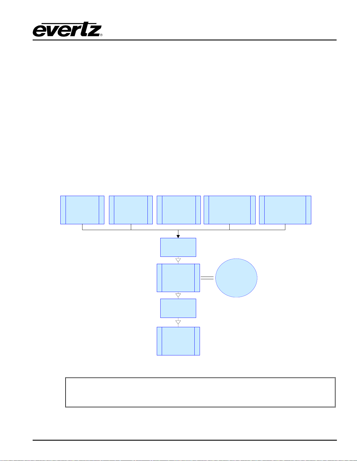
XRF1/XRF1A 16x16 RF Router Manual
5. CONTROL PANEL OPERATION SPECIFICATION
5.1. [PANEL LOCK] FUNCTION
Panel Lock can be initiated from any mode. When Panel Lock is enabled from any mode, the display
screen will timeout after 30 seconds and return to Destination Selection Mode. If a user manipulates any
buttons or knobs on the control panel while Panel Lock is enabled, a “PANEL LOCKED” message will be
displayed for 2 seconds and the display will then return to Destination Selection Mode. (Refer to section
4.3.5 for a further description of the Panel Lock display function.)
5.1.1. [PANEL LOCK] Enable
Press [PANEL LOCK]
All buttons are “locked out” of use and the PANEL LOCK LED is illuminated.
5.1.2. [PANEL LOCK] Disable
Press [PANEL LOCK]
All buttons are available for use and the PANEL LOCK LED is dark.
XRF1 Control Panel is in default Destination Selection Mode.
SOURCE
SELECTION
MODE
panel unlocked
DESTINATION
SELECTION
MODE
panel unlocked
Figure 5-1: Panel Lock Operation
SALVO
SELECTION
MODE
panel unlocked
PRESS
[PANEL LOCK]
DESTINATION
SELECTION
MODE
panel locked
PRESS
[PANEL LOCK]
DESTINATION
SELECTION
MODE
panel unlocked
CONFIGURATION
MENU MODE
panel unlocked
(DISPLAY)
“PANEL
LOCKED”
when any buttons/
knobs are
manipulated
CONFIGURATION
SET MODE
panel unlocked
If ‘Panel Lock” is enabled from Configuration Menu or Configuration Set Modes,
the panel will timeout after 30 seconds and return to Destination Selection Mode
"
without saving any configuration parameter changes.
CONTROL PANEL OPERATION Revision 1.2 XRF1 - 5-1
Page 42
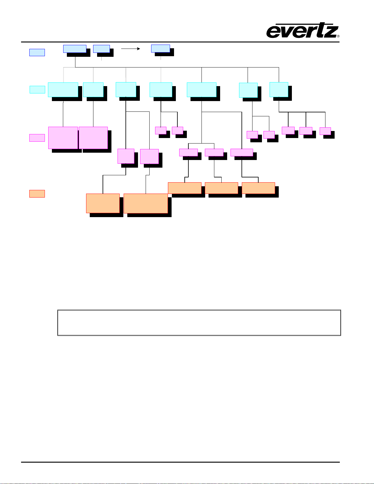
XRF1/XRF1A 16x16 RF Router Manual
LEVEL 1
LEVEL 2
LEVEL 3
LEVEL 4
ALL INPUTS INPUT 1
INPUT LEVEL
( ind. ch )
Statuses current
Input Level
-5 to -70 dBm
INPUT 16
….. …..
OUTPUT
LEVEL
Statuses current
Output Level
-20 to -50 dBm
SETS OUTPUT LEVEL
Displays -20dBm (allows
parameter setting in 1dBm
increments to -50dBm)
GAIN
MODE
AGC
MODE
MANUAL
GAIN
MODE
SETS OUTPUT VS. INPUT GAIN
DIFFERENCE
Displays 0dB (allows parameter
setting in 1dB increments from -
15dB to -16dB)
SQUELCH
RF
THRESHHOLD
OFFON
UPPER LOWER SQUELCH
Displays -5dBm (allows
parameter setting in 1dBm
increments to -30dBm)
Displays -70dBm (allows
parameter setting in 1dBm
increments to -31dBm)
LNB
RESET
YES
Displays -70dBm (allows
parameter setting in 1dBm
increments to -50dBm)
NO
Figure 5-2: Configuration Menu Structure per Input Channel
LNB
POWER
+13V
+18V
OFF
5.2. [INPUT] SELECT FUNCTION
5.2.1. [INPUT] Function from Destination Selection Mode
Press [INPUT]
This toggles to Source Selection Mode.
5.2.2. [INPUT] Function from Salvo Selection Mode
NOTE: [INPUT] and [OUTPUT] are pressed simultaneously to initiate Salvo Selection
"
Mode (from within Salvo Selection Mode)
Press [INPUT]
This exits Salvo Selection Mode and enters Source Selection Mode.
5.2.3. [INPUT] Function from Configuration Menu Mode
Press [INPUT]
This exits the Configuration Menu and enters Source Selection Mode.
5.2.4. [INPUT] Function from Configuration Set Mode
Press [INPUT]
This exits Configuration Set Mode, without making configuration changes, and enters Source Selection
Mode.
XRF1 - 5-2 Revision 1.2 CONTROL PANEL OPERATION
Page 43
XRF1/XRF1A 16x16 RF Router Manual
When the user exits Source Selection Mode, or after 30 seconds of inactivity, the
"
5.3. [OUTPUT] SELECT FUNCTION
5.3.1. [OUTPUT] Function from Source Selection Mode
Press [OUTPUT]
This toggles to Destination Selection Mode.
5.3.2. [OUTPUT] Function from Salvo Selection Mode
"
Press [OUTPUT]
This exits Salvo Selection Mode and enters Destination Selection Mode.
XRF1 Control Panel returns to Destination Selection Mode.
[INPUT] and [OUTPUT] are pressed simultaneously to initiate Salvo Selection Mode
(from within Salvo Selection Mode)
5.3.3. [OUTPUT] Function from Configuration Menu Mode
Press [OUTPUT]
This exits the Configuration Menu and enters Destination Selection Mode.
5.3.4. [OUTPUT] Function from Configuration Set Mode
Press [OUTPUT]
This exits Configuration Set Mode, without making configuration changes and enters Destination Selection
Mode.
5.4. [MENU] FUNCTION
The XRF1 user has the option to enable passcode protection, through VistaLINK
to Configuration Menu Mode. Setting and enabling of the menu passcode is processed only through
Evertz’s VistaLINK
When passcode protection has been enabled, pressing [MENU] prompts for an Administrator-level 4-digit
passcode. If passcode protection is never enabled through VistaLINK
Configuration Menu directly. Refer to Figure 5-3 for the operation flow for accessing the Configuration
Menu Mode.
5.4.1. [MENU] Function from Source and Destination Selection Modes –
Passcode Protection Enabled
. The XRF1 is only responsible for querying the user for the passcode when required.
®
, pressing [MENU] will enter the
®
software, limiting access
®
Press [MENU]
When enabled, this action displays a prompt for the 4-digit Administrator-level passcode.
The user enters the passcode configured through VistaLINK
Press [ENTER]
Initiates Configuration Menu Mode and prompts for input channel selection.
CONTROL PANEL OPERATION Revision 1.2 XRF1 - 5-3
®.
Page 44
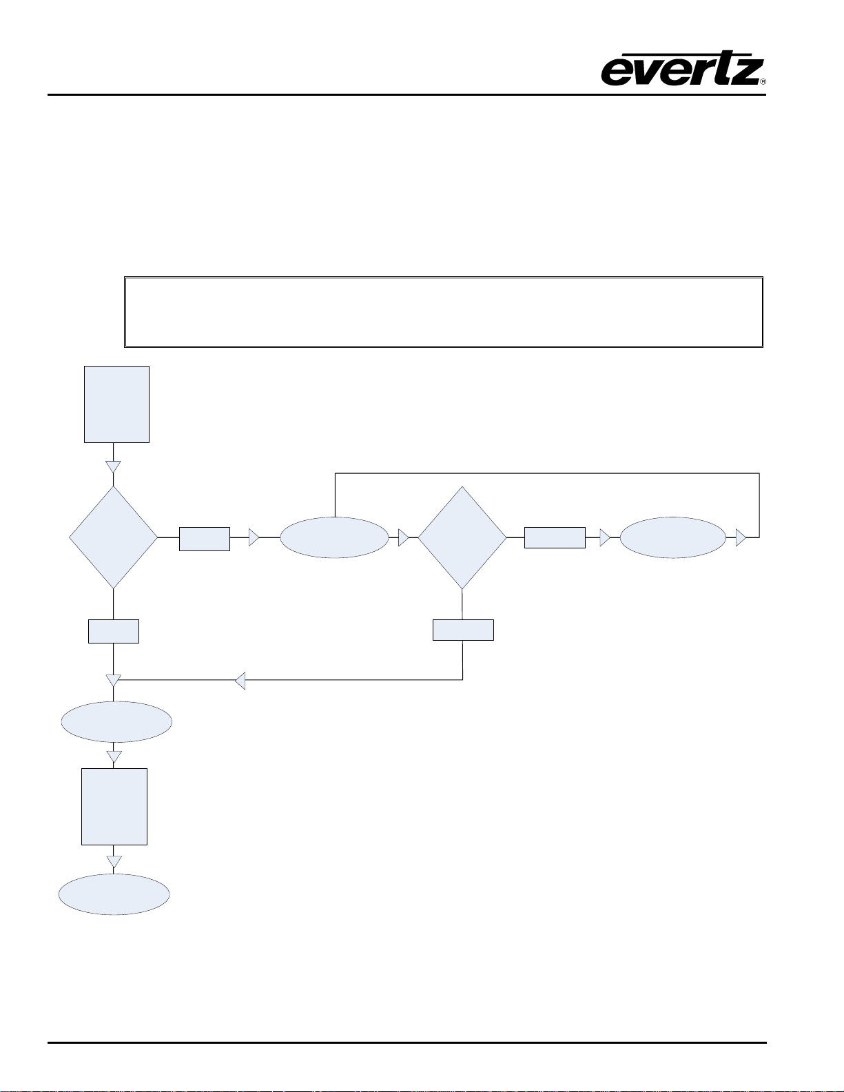
XRF1/XRF1A 16x16 RF Router Manual
5.4.2. [MENU] Function from Source and Destination Selection Modes –
Passcode Protection Not Enabled
Press [MENU]
Initiates Configuration Menu Mode and prompts for input channel selection.
5.4.3. [MENU] Function from Configuration Menu Mode or Configuration Set Mode
Press [MENU]
Returns the user to Menu Level 1 and prompts for Input channel selection.
When the user exits Configuration Set Mode, or after 30 seconds of inactivity, the
"
XRF1 Control Panel returns to Destination Selection Mode without making changes
to configuration parameters.
PRESS
[ME N U ]
Has Passcode
Been Set?
NO
(PR O MP T )
“CONFIGURE INPUT”
PRESS
[EN T E R ]
(DIS P L A Y )
ALL INPUTS
Is Passcode
Correct
or
Incorrect?
CORRECT
YES
(PR O MPT)
“ENTER CODE _ _ _ _”
Figure 5-3: Configuration Menu Access Operation
INCORRECT
(DIS P L A Y )
“INVALID CODE”
XRF1 - 5-4 Revision 1.2 CONTROL PANEL OPERATION
Page 45

5.5. DESTINATION [LOCK] FUNCTION
XRF1/XRF1A 16x16 RF Router Manual
The XRF1 user also has the option to enable passcode protection, through VistaLINK
access to the Lock feature on the router destinations. All setting, enabling, and disabling of passcodes is
accomplished through Evertz’ VistaLINK
responsible for querying the user for a passcode when required. Refer to Figure 5-4 for the operation flow
for accessing the Destination Lock function.
Passcode protection for the Lock function may be configured on two levels, Operator and Administrator.
There may be up to 8 Operator-level passcodes, but only one Administrator-level passcode distributed for
the system.
Operator Level: This level of protection allows a system operator, with an Operator-level 4-digit
passcode, to enable a “lock” on any selected destination. To disable the lock on a
selected destination, the same 4-digit Operator-level code, or the Administratorlevel code is required.
Administrator Level: This level of protection allows system managers, with the Administrator-level 4-
digit passcode, to enable a “lock” on any selected destination. To disable the lock
on a selected destination, only the Administrator-level code is accepted.
When passcode protection has been enabled, pressing [LOCK] from Destination
Selection Mode prompts the user for a 4-digit passcode. If passcode protection is
never enabled through VistaLINK
Mode will enable a “lock” on the selected destination without prompting for a
passcode.
, not through the XRF1 Control Panel. The XRF1 is only
®
, pressing [LOCK] from Destination Selection
®
software, limiting
®
5.5.1. [LOCK] Function
The Lock function can only be used from Destination Selection Mode:
TO ENABLE:
1. Navigate to desired destination
2. Press [LOCK]
3. Displays a prompt for a 4-digit passcode
4. The user enters the 4-digit passcode
5. Press [ENTER]
6. LOCK LED will blink at 2Hz. when any “locked” destination is selected
TO DISABLE:
1. Navigate to desired “locked” destination
2. Press [LOCK]
3. Displays a prompt for a 4-digit passcode
4. The user enters the 4-digit passcode
5. Press [ENTER]
6. LOCK LED will be dark when any “unlocked” destination is selected
When a Lock enable or disable process is completed, or after 30 seconds of inactivity,
"
the XRF1 Control Panel will return to the previous mode, Destination Selection Mode.
CONTROL PANEL OPERATION Revision 1.2 XRF1 - 5-5
Page 46
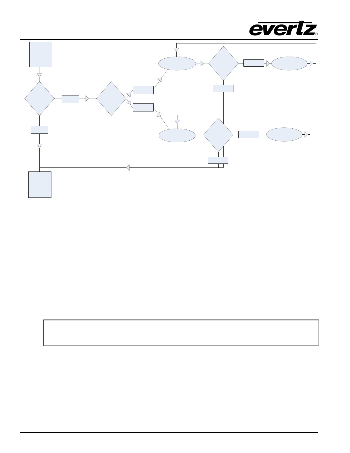
XRF1/XRF1A 16x16 RF Router Manual
PRESS
[LOCK]
(PROM P T)
“ADMIN CO D E _ _ _ _”
Is Passcode
Correct
or
Incorrect?
INCORRECT
(DISP L A Y )
“INVALID CODE”
CORRECT
Is Passcode
Correct
or
Incor re ct ?
CORRECT
Has Passcode
Been Set?
NO
ENABLES
LOCK ON
SELECTED
DESTINATION
YES
Is Passcode
Admin
or
Operator?
ADMIN
OPERATOR
(PRO MPT )
“ENTER CODE _ _ _ _”
Figure 5-4: Destination Lock Access Operation – Enabling a Destination Lock
5.6. DESTINATION [PROTECT] FUNCTION
The Lock function can only be used from Destination Selection Mode.
TO ENABLE:
1. Navigate to desired destination.
2. Press [PROTECT].
3. PROTECT LED will blink at 2Hz when any “protected” destination is selected
TO DISABLE:
1. Navigate to the desired “protected” destination.
2. Press [PROTECT].
3. PROTECT LED will be dark when any “unprotected” destination is selected
When a Protect enable or disable process is completed, or after 30 seconds of
inactivity, the XRF1 Control Panel will return to the previous mode, Destination
"
Selection Mode.
INCORRECT
(DISPLAY)
“INVALID CODE”
5.7. [TAKE] FUNCTION
The [TAKE] button performs the physical crosspoint connection within the XRF1 router. A “take” can only
be initiated from Source Selection Mode, Destination Selection Mode, or Salvo Selection Mode. Pressing
[TAKE] will perform the physical crosspoint change for the current statuses input/output pairing or the
currently selected salvo.
One example of how a typical crosspoint change (for source “TELSTAR 12” and destination “IRD 16”) may
be performed is as follows:
XRF1 - 5-6 Revision 1.2 CONTROL PANEL OPERATION
Page 47
XRF1/XRF1A 16x16 RF Router Manual
Navigate to desired destination --- using the up/down arrow keys, the scroll knob,
or 0-9 numeric buttons
Depress the scroll knob --- enters Source Selection Mode
Navigate to desired source --- using the up/down arrow keys, the scroll knob,
or 0-9 numeric buttons
[TAKE] --- performs physical router connection between
“TELSTAR 12” and “IRD 16”
--- displays “TAKE SUCCESSFUL” for 2 seconds, then return s to
Destination Selection Mode
An example of how a salvo (named “ALL CALL SOURCE 5” – input channel 5 to all destinations) is
executed is as follows:
Navigate to desired salvo --- using the up/down arrow keys, the scroll knob,
or 0-9 numeric buttons
[TAKE] --- performs physical router connection between
input channel 5 and all destinations
--- displays “TAKE SUCCESSFUL” for 2 seconds, then return s to
Destination Selection Mode
After a “take” is completed, from any selection mode, the 16-character screen will
"
display a “TAKE SUCCESSFUL” message for 2 seconds. The display will then return
to the previous mode and display the last manipulated input/output pairing or salvo.
5.8. [ENTER] FUNCTION
5.8.1. [ENTER] Function from Destination Selection Mode
1. Navigate to desired destination
2. Press [ENTER]
Toggles to Source Selection Mode
NOTE: The [ENTER] key does not perform physical crosspoint changes. The [ENTER]
"
"
5.8.2. [ENTER] Function from Source Selection Mode
1. Navigate to desired source
2. Press [ENTER]
"
key cannot perform a [TAKE].
NOTE: Pressing [ENTER] while a salvo is selected is a NO OP. The [ENTER] key cannot
perform a [TAKE].
Toggles to Destination Selection Mode
NOTE: The [ENTER] key does not perform physical crosspoint changes. The [ENTER]
key cannot perform a [TAKE].
CONTROL PANEL OPERATION Revision 1.2 XRF1 - 5-7
Page 48
XRF1/XRF1A 16x16 RF Router Manual
5.8.3. [ENTER] Function from Configuration Menu Mode
1. Navigate to desired menu option
2. Press [ENTER]
Finalizes menu choice and moves down one menu level
5.8.4. [ENTER] Function from Configuration Set Mode
1. Navigate to desired configuration parameter and perform desired change to settings.
2. Press [ENTER]
Performs physical changes to parameter settings and displays a “CHANGES SAVED” message
Moves back up one menu level
NOTE: It is necessary to press [ENTER] after making any configuration parameter changes,
"
or the changes will not take place. If the user exits Configuration Set Mode without pressing
[ENTER], no changes will be made to the physical router settings.
XRF1 - 5-8 Revision 1.2 CONTROL PANEL OPERATION
Page 49
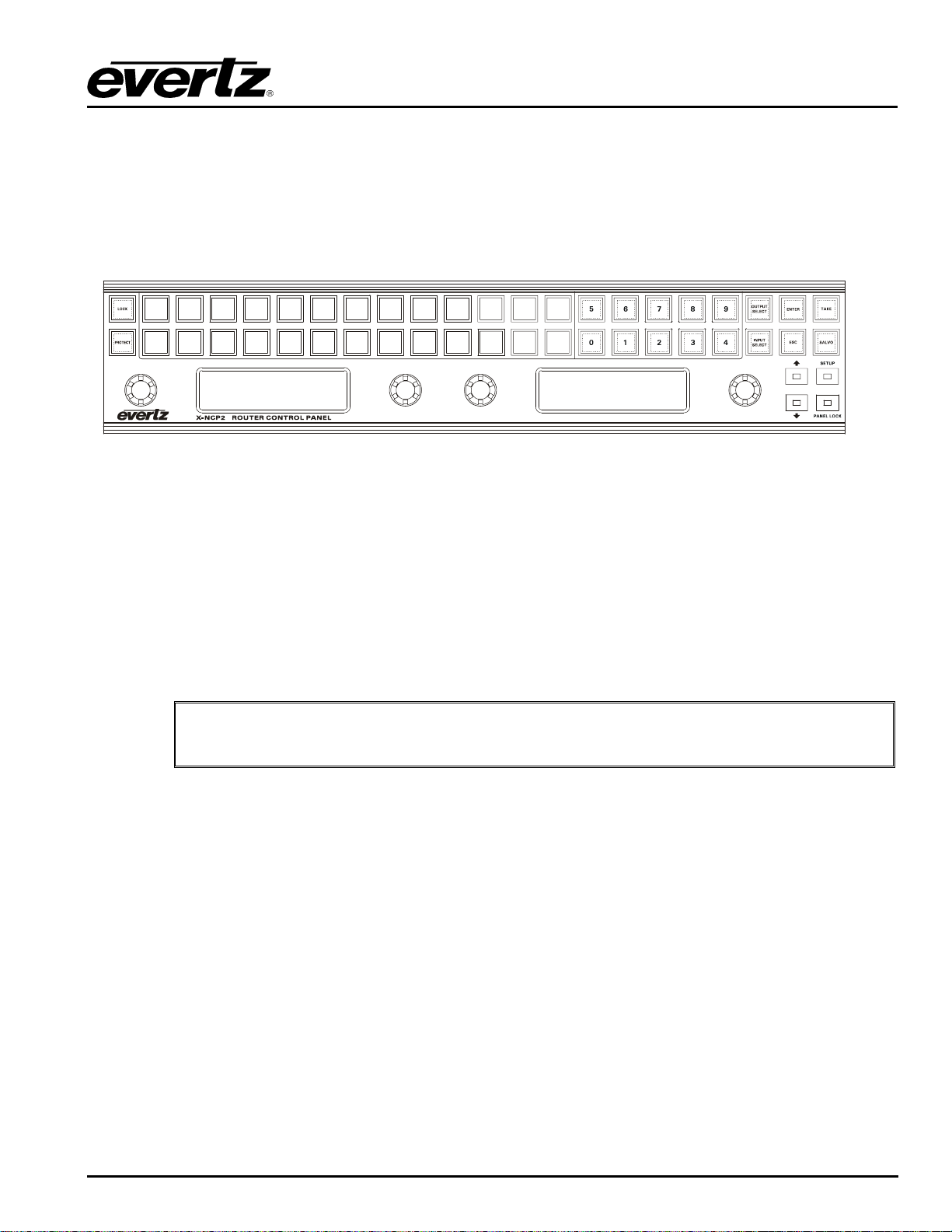
XRF1/XRF1A 16x16 RF Router Manual
6. OPERATION
The router matrix may be controlled via SNMP over the Ethernet port or by RS232/422 over the frame’s
serial port. The Evertz X-NCP2 control panel uses SNMP over Ethernet, while many third party M&C
systems use the RS232/422 port.
6.1. X-NCP2 ROUTER CONTROL PANEL
The Evertz X-NCP2 control panel is a multi-function control panel used to control the XRF series of
routers, and X Series of optical routers. The display area consists of a two 24 digit alphanumeric displays,
0-9 numeric keypad, 12 functional push-buttons and tactile rotary encoders with push-button selection.
6.1.1. Connections
The control panel may be connected directly to the router’s Ethernet port (using a crossover Ethernet
cable) or to a hub or switch, which is connected to the router’s Ethernet port (using a standard Ethernet
cable). A hub or switch is required to connect multiple control panels to a frame controller. The panel
communicates with the router’s frame controller using SNMP. A single XRF1 may have up to eight XNCP2 panels connected to it on the same network. Conversely, a single X-NCP2 panel can control
multiple connected XRF1’s.
To connect an XNCP2 control panel directly to an XRF1 router Ethernet port, a
"
6.1.2. Mounting
The X-NCP2 is equipped with rack mounting brackets and fits into a standard 19 inch by 1 3/4 inch (483
mm x 45 mm) rack space. 2RU of vertical space is required. The mounting brackets may be removed if
rack mounting is not required.
crossover Ethernet cable is required.
OPERATION Revision 1.2 XRF1 - 6-1
Page 50

XRF1/XRF1A 16x16 RF Router Manual
6.1.3. Specifications
6.1.3.1. Serial I/O (COM 1)
Standard: RS-232
Connector: Female DB-9
Baud Rate: 57600
Format: 8 bits, no parity, 2 stop bits, no hardware flow control (COM2 not available)
6.1.3.2. Ethernet I/O
Standard: IEEE 802.3 (10BaseT), IEEE 8002.3u (100BaseTx)
Connector: 1 RJ45
Cable Requirements:
10 Base T: UTP category 3, 4 or 5 cable up to 328ft/100m (2 pairs)
100 Base Tx: UTP category 5 cable up to 328ft/100m (2 pairs)
6.1.3.3. Electrical
Voltage: 100-240VAC, 50/60 Hz auto-ranging
Power: 11 Watts
EMI/RFI: Complies with FCC Part 15, class A and EU EMC directive.
6.1.3.4. Physical
Size: 17 1/8” W x 4 3/8” D x 3 ½” H (435mm x 111mm x 89mm)
Weight: 4 lbs. (1.81 kg)
Temperature: 0 to 50 deg. C. (Operating)
6.1.4. X-NCP2 Configuration Menu
When power is applied to the unit, the X-NCP2 provides a set-up menu with the following parameters:
<back> Conveniently located at the start and end of a menu stack, this menu item allows the
user to return to the previous menu for further configuration, if required.
Network Setup: Set the IP address of the X-NCP2 unit, its subnet mask and gateway IP.
Configuration: N/A
Service: N/A
Reboot: A menu option that allows the user a quick way to reboot the X-NCP2 unit without
unplugging the AC power source from the unit. Options are “yes” and “cancel”.
Discovery: N/A
Add Frame: Menu option to add routers to the X-NCP2 control list
Remove Frame: Menu option to remove routers from the available list.
Request update: N/A
XRF1 - 6-2 Revision 1.2 VISTALINK
Page 51

XRF1/XRF1A 16x16 RF Router Manual
6.1.5. Setting the X-NCP2 IP Address
The X-NCP2 should be configured on the same subnet as the connected router(s).
Follow this procedure to configure the X-NCP2 IP address:
1. Enter the <setup> menu at the top level menu of the X-NCP2.
2. Enter the <Network> item in the list.
3. Select the <IP Address> item in the list.
4. Enter the desired IP address of the XRF1 using the scroll knob, press the knob to move to the next
set of digits in the IP address.
5. When complete, the XNCP2 will return to the Network Setup menu. Configure other network
settings as required using the above procedure.
6.1.6. Adding XRF1 Router to XNCP2 Control List
The X-NCP2 should be configured to be on the same subnet as the connected router(s).
The addition of XRF1 routers can be performed once the X-NCP2 panel and XRF1 IP addresses are on the
same IP subnet.
Follow this procedure to add routers to the X-NCP2 control list.
1. Enter the <setup> menu at the top level menu of the X-NCP2.
2. Enter the <add frame> item in the list.
3. Select the frame type as <NON-SNMP>.
4. Enter the IP address of the XRF6 frame controller using the scroll knob and [SETUP] key.
5. The XNCP2 will update and display the IP address of the added frame controller.
The same procedure can be followed to remove an XRF1 from the XNCP2 list, except in step 2, select
<remove frame> instead of <add frame>. The panel will not require specification of frame type to remove
the frame address.
6.1.7. Initiating a Control Session with an XRF1
To control the router matrix, a panel session with the frame controller must first be initiated. This is
accomplished by using the rotary knob to highlight the IP address of the router to be controlled and
pressing the [SELECT] button on the panel.
If there is more than one device on the network, the panel will show multiple IP addresses (or names, if
configured) in the display. Use the rotary knob to highlight the desired device, then press [SELECT] to
initiate a session with that device.
OPERATION Revision 1.2 XRF1 - 6-3
Page 52
XRF1/XRF1A 16x16 RF Router Manual
Once a session is initiated, the left hand window of the X-NCP2 will display the type of router connected
(i.e. XRF1 Router) and the range of available inputs and outputs. The right-hand window will show the
current status of input and output routes (destination select mode). Rotating any of the shaft encoders will
increment the crosspoint displayed in the order of the outputs.
6.1.8. Terminating a Control Session with an XRF1
To manually terminate a session at any time, simultaneously press the [↑] and [↓] keys to return to the list
of router IP addresses.
6.1.8.1. Controlling Crosspoints Using the X-NCP2
Once a session is initiated, crosspoint changes may be made by using the [Output Select] and [Input
Select] buttons, followed by the [TAKE] button. As an alternative to using the pushbuttons for input and
output selection, the scroll knobs on either side of the display may be used for output and input selection,
followed by the [TAKE] button.
The examples listed below illustrate two different methods of initiating a crosspoint take with the router.
Both examples illustrate making a connection between output 5 and input 2.
6.1.8.2. Example 1: Pushbutton control to switch input 2 to output 5
1) Initiate a panel session by highlighting the IP address (or router name) of the router in the display
area of the panel. This is done using the leftmost scroll knob. When the frame IP address (or
name) is highlighted, press [SELECT].
2) Press [OUTPUT SELECT] to put the panel into output selection mode. The numeric buttons 0-9 will
illuminate.
3) Use the numeric buttons to select the desired output (i.e. 5) by pressing [5], followed by [OUTPUT
SELECT] to exit output selection mode.
4) Press [INPUT SELECT] to put the panel into input selection mode. The numeric buttons 0-9 will
illuminate.
5) Use the numeric buttons to select the desired input (i.e. 2) by pressing [2], followed by [INPUT
SELECT] to exit the input selection mode.
6) Press [TAKE]. The panel display will display the input and output selected, plus a “take successful”
message. The router does not perform the input to output connection until the [TAKE] button is
pressed.
In short, the steps are [SELECT], [OUTPUT SELECT], [2], [OUTPUT SELECT], [INPUT SELECT], [2],
[INPUT SELECT], [TAKE].
NOTE: The control panel session will time out after approximately 30 seconds of
"
no panel activity.
6.1.8.3. Example 2: Rotary knob control to switch input 2 to output 5
1. Initiate a panel session by highlighting the IP address (or router name) of the router in the display
area of the panel. This is done using the leftmost scroll knob. When the frame IP address (or
name) is highlighted, press [SELECT].
2. Use the left scroll knob (of the right side display area) to select an output. As you scroll through
the system outputs, the current input connection is displayed.
3. Use the right knob to select the desired input.
XRF1 - 6-4 Revision 1.2 VISTALINK
Page 53

XRF1/XRF1A 16x16 RF Router Manual
4. To make the crosspoint selection, press [TAKE]. A “take successful” message should appear in the
display.
6.1.9. Control Configuration Items with the X-NCP2
Once a session is initiated, configuration changes may be made by pressing the [SETUP] button and using
the rotary encoder to select the desired configuration value, then pressing enter to select it. Configurable
values and the method of setting them is the same as doing so with the local control panel, as outlined
beginning in section 4.5.
6.1.10. Panel Lock Button
The panel lock function works the same as on the XRF-1 local control panel. Refer to section 5.1 for
details.
6.1.11. Lock Button
The destination lock function works the same as on the XRF-1 local control panel. Refer to section 5.5 for
details.
6.1.12. Protect Button
The destination protect function works the same as on the XRF-1 local control panel. Refer to section 5.6
for details.
6.1.13. Salvo Select Button
Pressing this button allows access to up to 8 pre-programmed salvos that have been configured using
Evertz VistaLINK
software.
®
A SALVO is a pre-programmed sequence of crosspoint connections that can be constructed using
VistaLINK
and executed from the XRF1 Control Panel or X-NCP2. Execution of a salvo is very similar to
®
execution of an individual crosspoint connection, but the entire list of connections contained in the salvo is
performed.
To execute a salvo, press the [SALVO SELECT] button and use the scroll knob to browse the available
salvos. Press the [TAKE} button to execute the desired salvo.
6.1.14. Escape Key
The [ESC] key may be used to move up one menu level. At the top level of the configuration menu, it will
exit this mode and return to Destination select menu mode (default). Pressing the [ESC] key prior to the
[ENTER] or [TAKE] keys will exit the current configuration item without performing any crosspoint or
configuration changes.
OPERATION Revision 1.2 XRF1 - 6-5
Page 54

XRF1/XRF1A 16x16 RF Router Manual
This page left intentionally blank
XRF1 - 6-6 Revision 1.2 VISTALINK
Page 55

XRF1/XRF1A 16x16 RF Router Manual
7. VISTALINK® REMOTE MONITORING/CONTROL
7.1. WHAT IS VISTALINK®?
VistaLINK
is Evertz’ remote monitoring and configuration platform which operates over an Ethernet
®
network using Simple Network Management Protocol (SNMP). SNMP is a standard computer network
protocol that enables different devices sharing the same network to communicate with each other.
VistaLINK
provides centralized alarm management, which monitors, reports, and logs all incoming alarm
®
events and dispatches alerts to all the VLPro Clients connected to the server. Card configuration through
VistaLINK
routines, which reduces the time to configure each module separately. Finally, VistaLINK
PRO can be performed on an individual or multi-card basis using simple copy and paste
®
enables the
®
user to configure devices in the network from a central station and receive feedback that the configuration
has been carried out.
There are 3 components of SNMP:
1. An SNMP manager, also known as a Network Management System (NMS), is a computer running
special software that communicates with the devices in the network. Evertz VistaLINK
®
-C
Configuration Utility graphical user interface (GUI), third party or custom manager software may be
used to monitor and control Evertz VistaLINK
enabled products.
®
2. Managed devices, each with a unique address (OID), communicate with the NMS through an SNMP
Agent. The XRF1/XRF1A communicates directly with the manager using its internal Agent.
3. A virtual database known as the Management information Base (MIB) lists all the variables being
monitored, which both the Manager and Agent understand. Please contact Evertz for further
information about obtaining a copy of the MIB for interfacing to a third party Manager/NMS.
7.2. V
ISTALINK
The VistaLINK
INTERFACE
®
control, configuration, and monitoring software application may be used to configure
®
and control the XRF1 router, as well as monitor alarms (SNMP traps) within the system. The
following items may be controlled or configured through the VistaLINK
interface:
®
• Router crosspoint settings
• Manual or AGC mode on each input
• Power level for each input (AGC mode)
• Gain on each input (manual gain mode)
• Input squelch mode (on or off)
• Input squelch threshold
• Salvo Save / Recall / Execute
• Password Control
The following items may be monitored through the VistaLINK
software:
®
• Input RF power level (high or low)
• Crosspoint status
• LNB short circuit detection
VISTALINK Revision 1.2 XRF1 - 7-1
Page 56
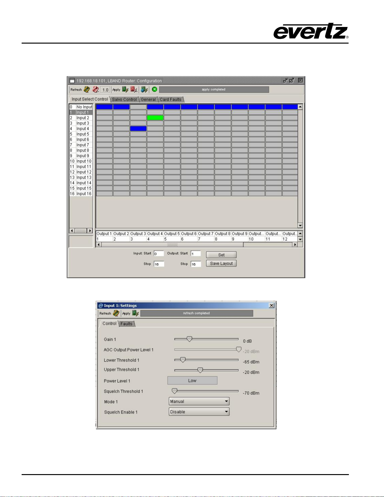
XRF1/XRF1A 16x16 RF Router Manual
The following screen capture shows the VistaLINK® crosspoint control matrix and the configuration menu
available for each router input. For more information on the VistaLINK
an Evertz sales representative or visit www.evertz.com.
suite of products, please contact
®
Figure 7-1: VistaLINK
Configuration Menu for each Router Input
®
Figure 7-2: VistaLINK
Crosspoint Cross Matrix
®
XRF1 - 7-2 Revision 1.2 VISTALINK
Page 57

XRF1/XRF1A 16x16 RF Router Manual
8. TECHNICAL DESCRIPTION
8.1. SPECIFICATIONS
8.1.1. SYSTEM
Matrix Size: 16x16 in a 1RU frame
System Expansion: Inputs and outputs are expandable in increments of 16
32x32 maximum expanded system size using external distribution and
combining with SRF series passive splitter/combiners
Gain Range: (manual gain mode):
XRF1: –9 to +18 dB
XRF1A: -10 to +12 dB
Output AGC Level: –20 to –50 dBm
8.1.2. RF Specifications: L Band
Bandwidth: 850 to 2250 MHz*
Frequency Response: +/- 1.5 dB over the passband, +/- 0.5 dB over any 36 MHz channel
Isolation: > 60dB (input to output)
> 70dB (output to output)
> 70dB (input to input)
RF Input Power: -10 to –70 dBm
Maximum RF Output Power: -10dBm
Input P1dB: +2 dBm (1500MHz) typ
OIP3: +12dBm (1500MHz) typ
Max RF Output Power: –10 dBm
Noise Figure:
XRF1: 6dB (1500MHz, Gain = +18dB) typ, 20dB (1500MHz, Gain = 0dB) typ
XRF1A: 6dB (1500MHz, Gain = +12dB) typ, 15dB (1500MHz, Gain = 0dB) typ
Connector Type: BNC per IEC 61169-8, Annex A (F connector optional – accepts
conductor range 21-19 AWG (0.41-0.64 mm
Impedance: 75 ohm (50 ohm BNC optional)
Return Loss:
XRF1: > 15 dB (input and output)
XRF1A: > 15 dB output, >13 dB input
2
) on center pin)
8.1.3. RF Specifications: IF
Bandwidth: 40 to 200 MHz
Frequency Response: +/- 0.5 dB over 50-90MHz and 120-160MHz
Isolation: > 60dB (input to output)
> 70dB (output to output)
> 70dB (input to input)
RF Input Power: -15 to –70 dBm
Maximum RF Output Power: -10dBm
Input P1dB: -4 dBm (70MHz) typ
OIP3: +10dBm (70MHz) typ
Return Loss:
XRF1: > 15 dB (input and output)
XRF1A: > 15 dB output, >13 dB input
* All specifications over specified bandwidth unless noted.
SPECIFICATIONS Revision 1.2 XRF1 - 8-1
Page 58

XRF1/XRF1A 16x16 RF Router Manual
8.1.4. LNB Power (LNB option only)
LNB Maximum Output Current (per connector): 400 mA @ +13/+17 VDC (selectable)
8.1.5. Communication and Control
Serial: RS232/RS422 selectable – Female 9 pin D connector
Ethernet: SNMP over IEEE 802.3/U (10/100 BaseTx) RJ45 connector
Control: Front panel, VistaLINK
Control Panels: X-NCP2
8.1.6. Electrical
AC Mains Input: Auto ranging, 100 Ù 240 VAC, 50/60 Hz
Maximum Power Consumption:
40 Watts max. w/o LNB power option
175 Watts max. with LNB power option
Power Supply Configuration: 1 supply standard, optional redundant supply requires separate inlet
Connector: IEC 60320 - 1 per power supply
Fuses:
Standard: 1 amp, 250 Volt time delay 5 x 20 mm (T1AL250V). – 2 per PSU
LNB option: 4 amp, 250 Volt time delay 5 x 20 mm (T4AL250V). – 2 per PSU
®
8.1.7. Compliance
Safety: CSA Listed to CSA C22.2 No. 60065-03, UL 60065-03
IEC 60065-(2001-12) 7th Edition
Complies with CE Low voltage Directive 93/68/EEC
EMC: Complies with FCC part 15, class A
Complies with EU EMC directive 89/336/EEC
8.1.8. Physical
Height: 1.75” (45 mm)
Width: 19” (483 mm)
Depth: 18.75” (477 mm)
Weight: Approx. 7.4 lbs. (7.9 Kg)
Temperature: 0 - 40°C
XRF1 - 8-2 Revision 1.2 SPECIFICATIONS
Page 59
XRF1/XRF1A 16x16 RF Router Manual
8.2. SERVICING INSTRUCTIONS
CAUTION – These servicing instructions are for use by qualified service
personnel only. To reduce the risk of electric shock do not perform any
servicing instructions in this section of the manual unless you are qualified
to do so.
8.2.1. Changing the Fuses
Check that the line fuse is rated for the correct value marked on the rear
panel. Never replace with a fuse of a greater value.
The fuse holder is located inside the power entry module. To change the fuses, remove the fuse holder
from the power entry module using a small screwdriver. The fuse holder contains two fuses, one for the
line and one for the neutral side of the mains connection. Remove the blown fuse and replace it with a
fuse of the correct value. Replacement fuse type: T1AL250V, slow blow, 1A, 250VAC (non LNB),
T4AL250V, slow blow, 4A, 250VAC (LNB option).
SPECIFICATIONS Revision 1.2 XRF1 - 8-3
Page 60

XRF1/XRF1A 16x16 RF Router Manual
This page left intentionally blank
XRF1 - 8-4 Revision 1.2 SPECIFICATIONS
 Loading...