

evertz X1201S-AES, X1202S-AES, X1201-AES4, X1202S, X1202-AES4 User Manual
...
© Copyright 2001, 2002, 2003
EVERTZ MICROSYSTEMS LTD.
5288 John Lucas Drive,
Burlington, Ontario,
Canada,
L7L 5Z9
X1200 Series Routers
Instruction Manual
Phone: 905-335-3700
Sales: sales@evertz.com Fax: 905-335-3573
Tech Support: service@evertz.com Fax: 905-335-0909
Web Page: http://www.evertz.com
Version 1.3.2, Feb 2003
The material contained in this manual consists of information that is the property of Evertz Microsystems and is intended solely for
the use of purchasers of the X1200 Series Routers. Evertz Microsystems expressly prohibits the use of this manual for any
purpose other than the operation of the Routers.
All rights reserved. No part of this publication may be reproduced without the express written permission of Evertz Microsystems
Ltd. Copies of this guide can be ordered from your Evertz products dealer or from Evertz Microsystems.

INFORMATION TO USERS IN EUROPE
NOTE
CISPR 22 CLASS A DIGITAL DEVICE OR PERIPHERAL
This equipment has been tested and found to comply with the limits for a Class A digital device, pursuant
to the European Union EMC directive. These limits are designed to provide reasonable protection against
harmful interference when the equipment is operated in a commercial environment. This equipment
generates, uses, and can radiate radio frequency energy and, if not installed and used in accordance with
the instruction manual, may cause harmful interference to radio communications. Operation of this
equipment in a residential area is likely to cause harmful interference in which case the user will be
required to correct the interference at his own expense.
INFORMATION TO USERS IN THE U.S.A.
NOTE
FCC CLASS A DIGITAL DEVICE OR PERIPHERAL
This equipment has been tested and found to comply with the limits for a Class A digital device, pursuant
to Part 15 of the FCC Rules. These limits are designed to provide reasonable protection against harmful
interference when the equipment is operated in a commercial environment. This equipment generates,
uses, and can radiate radio frequency energy and, if not installed and used in accordance with the
instruction manual, may cause harmful interference to radio communications. Operation of this equipment
in a residential area is likely to cause harmful interference in which case the user will be required to correct
the interference at his own expense.
WARNING
Changes or Modifications not expressly approved by Evertz Microsystems Ltd. could void the user’s
authority to operate the equipment.
Use of unshielded plugs or cables may cause radiation interference. Properly shielded interface cables
with the shield connected to the chassis ground of the device must be used

X1200 Series Router Manual
REVISION HISTORY
REVISION DESCRIPTION DATE
1.0 Original Version Oct 01
1.1 Changes for X1201 routers and SoftSwitch routers Jan 02
1.2 More descriptions added re SoftSwitch timing set-ups, Chapter 7 added Jan 02
1.2.1 Corrections to table 2-2, 2-4 and 2-5, Table 2-6 Added Feb 02
1.2.2 Features current for firmware version 1.1 build 23 May 02
Added Input Label File menu item for uploading Label Text files
1.3 Added information about Embedded SoftSwitch Jan 03
Added information about SoftSwitch on HD routers
1.3.1 Added clarification of Video switch line for HD routers Feb 03
1.3.2 Changed Block diagrams, added diagrams for Embedded SoftSwitch Feb 03
Information contained in this manual is believed to be accurate and reliable. However, Evertz assumes no responsibility for the use thereof nor for
the rights of third parties, which may be effected in any way by the use thereof. Any representations in this document concerning performance of
Evertz products are for informational use only and are not warranties of future performance, either express or implied. The only warranty offered
by Evertz in relation to this product is the Evertz standard limited warranty, stated in the sales contract or order confirmation form.
Although every attempt has been made to accurately describe the features, installation and operation of this product in this manual, no warranty is
granted nor liability assumed in relation to any errors or omissions unless specifically undertaken in the Evertz sales contract or order confirmation.
Information contained in this manual is periodically updated and changes will be incorporated into subsequent editions. If you encounter an error,
please notify Evertz Customer Service department. Evertz reserves the right, without notice or liability, to make changes in equipment design or
specifications.

X1200 Series Router Manual
This page left intentionally blank
Revision 1.3.2

X1200 Series Router Manual
TABLE OF CONTENTS
1. OVERVIEW....................................................................................................................................... 1-1
1.1. HOW TO USE THIS MANUAL ................................................................................................ 1-6
1.2. GLOSSARY............................................................................................................................. 1-6
2. INSTALLATION................................................................................................................................ 2-1
2.1. REAR PANEL.......................................................................................................................... 2-1
2.1.1. Standard Definition Digital Video Connections (X1200S) ............................................ 2-1
2.1.2. High Definition Digital Video Connections (X1202H) ................................................... 2-1
2.1.3. AES Audio Connections ............................................................................................... 2-2
2.1.3.1. Audio Connections on Router Models with the AES Option Fitted. ............. 2-2
2.1.3.2. Audio Connections On Early Router Models With The AES Option Fitted.
(two breakout panels shipped)..................................................................... 2-2
2.1.3.3. Audio Connections on Router Models with the AES4 Option Fitted. ........... 2-3
2.1.4. Reference Connections................................................................................................ 2-3
2.1.5. Remote Control Connections ....................................................................................... 2-3
2.1.6. Power Connections ...................................................................................................... 2-5
2.2. MOUNTING ............................................................................................................................. 2-5
2.3. POWER REQUIREMENTS...................................................................................................... 2-5
2.3.1. Selecting the Correct Mains Voltage ............................................................................ 2-5
2.3.2. Changing the Fuses ..................................................................................................... 2-6
2.4. CONNECTING THE REMOTE CONTROL PANEL ................................................................ 2-6
2.4.1. Connecting The Primary Remote Control Panel (RCP Version) .................................. 2-6
2.4.2. Connecting A Second Remote Control Panel .............................................................. 2-7
2.5. CONNECTING THE GENERAL PURPOSE INPUTS AND OUTPUTS .................................. 2-7
2.5.1. Connecting the General Purpose Inputs ...................................................................... 2-8
2.5.2. Connecting the General Purpose Outputs ................................................................... 2-9
2.5.3. GPI/O Examples........................................................................................................... 2-9
2.6. CONTROLLING THE ROUTER USING THE EXTERNAL SERIAL PROTOCOL ................ 2-10
2.6.1. Connecting the Router to a Grass Valley Ten XL ASCII Control Device ................... 2-10
3. OPERATION..................................................................................................................................... 3-1
3.1. OVERVIEW OF THE FRONT PANEL DISPLAY AND CONTROLS ...................................... 3-1
3.1.1. Video Router Controls .................................................................................................. 3-1
3.1.2. Setup Key Group.......................................................................................................... 3-1
3.1.3. Front Panel Display Messages..................................................................................... 3-2
3.2. OVERVIEW OF FRONT PANEL OPERATION....................................................................... 3-2
3.2.1. Audio Follow Video Switching (AFV)............................................................................ 3-2
3.2.2. Breakaway Audio On An Audio Follow Video Group ................................................... 3-3
3.2.3. Independent Audio Bus Switching ............................................................................... 3-4
3.3. FRONT PANEL SETUP MENU ............................................................................................... 3-4
3.4. NAGIVATING THE SETUP MENU.......................................................................................... 3-5
3.5. FRONT PANEL SETUP MENU – MAIN MENU ...................................................................... 3-6
3.6. CONFIGURING THE ROUTER REFERENCES...................................................................... 3-6
3.6.1. Setting up the Video Reference ................................................................................... 3-7
CONTENTS
Revision 1.3.2
i

X1200 Series Router Manual
3.6.2. Setting up the Video Output Timing
(SoftSwitch and Embedded SoftSwitch routers only) ............................................ 3-7
3.6.3. Setting up the Video Line Synchronizer Timing
(SoftSwitch and Embedded SoftSwitch equipped routers only)............................. 3-8
3.6.4. Setting up the AES Audio Reference
(SoftSwitch and Embedded SoftSwitch equipped routers only)............................. 3-8
3.7. CONFIGURING THE VIDEO AND AUDIO TRANSITIONS .................................................... 3-9
3.7.1. Configuring The Switch Line ........................................................................................ 3-9
3.7.2. Enabling The Video Line Synchronizer On For Clean Video Switches
(SoftSwitch and Embedded SoftSwitch equipped routers only)........................... 3-10
3.7.3. Enabling The AES Audio SoftSwitch For Clean Audio Switches
(SoftSwitch and Embedded SoftSwitch equipped routers only)........................... 3-10
3.7.4. Enabling The Embedded Audio SoftSwitch For Clean Audio Switches
(Embedded SoftSwitch equipped routers only)....................................................... 3-11
3.8. CONFIGURING THE VIDEO AND AUDIO INPUTS.............................................................. 3-11
3.8.1. Setting the Configuration of the AES Router Section
(Early X1202H-AES Routers with 2 breakout panels only) ........................................ 3-12
3.8.2. Setting up the Audio Follow Video Groups................................................................. 3-12
3.8.3. Configuring Which Inputs Are Active.......................................................................... 3-13
3.8.4. Configuring What To Do When There Is No Video Input Present .............................. 3-13
3.8.5. Configuring The Router Video Standard
(HD SoftSwitch and Embedded SoftSwitch equipped routers only) ................... 3-14
3.9. LABELING THE VIDEO AND AUDIO INPUTS..................................................................... 3-14
3.9.1. Uploading/Downloading Input Labels from a Text File............................................... 3-14
3.9.2. Changing the Input Labels from the Front Panel........................................................ 3-15
3.10. CONFIGURING THE VIDEO OUTPUTS (HD ROUTERS ONLY) ......................................... 3-15
3.10.1. Selecting the Reclocking Mode of the HD Video Outputs (HD Routers only) ............ 3-15
3.11. MANUALLY ACTIVATING THE BYPASS RELAYS ............................................................ 3-15
3.11.1. Manually Activating All the Bypass Relays................................................................. 3-16
3.12. CONFIGURING THE GENERAL PURPOSE INPUTS (GPI) ................................................ 3-16
3.12.1. How to Override (Temporarily Disable) the GPI Functions ........................................ 3-16
3.12.2. How to turn off the GPI Override (Return the GPIs to their Programmed Functions) 3-16
3.12.3. Configuring the Encoding mode for the GPI Inputs.................................................... 3-17
3.12.3.1. Standard GPI Encoding ............................................................................. 3-17
3.12.3.2. HEX GPI Encoding..................................................................................... 3-17
3.12.3.3. AFV HEX GPI Encoding............................................................................. 3-18
3.12.4. Configuring Whether the GPI Inputs are Edge or Level Activated ............................. 3-19
3.12.5. Programming the GPI Inputs Functions ..................................................................... 3-20
3.13. CONFIGURING THE GENERAL PURPOSE OUTPUTS (GPO)........................................... 3-20
3.13.1. How to Override (Temporarily Disable) the GPO Functions ...................................... 3-21
3.13.2. How to turn off the GPO Override (Return the GPOs to their Programmed Functions)321
3.13.3. Configuring the Encoding mode for the GPO Outputs ............................................... 3-21
3.13.3.1. HEX GPO Encoding................................................................................... 3-21
3.13.4. Configuring Whether the GPO Outputs are Latched or Momentary........................... 3-22
3.13.5. Programming the GPO Output Functions .................................................................. 3-22
ii
Revision 1.3.2
CONTENTS

X1200 Series Router Manual
3.14. CONFIGURING THE REMOTE CONTROL PORT OPERATION......................................... 3-22
3.14.1. Selecting the Baud Rate for Remote Control Port...................................................... 3-23
3.14.2. Selecting the Serial Data Format for the Remote Control Port .................................. 3-23
3.14.3. Selecting the Serial Control Address.......................................................................... 3-24
3.14.4. Selecting the Serial Data Control Mode ..................................................................... 3-24
3.14.5. Selecting the External Remote Control Protocol ........................................................ 3-24
3.15. SAVING AND RECALLING CONFIGURATION PRESETS ................................................. 3-25
3.15.1. How to Restore the Factory Default Settings ............................................................. 3-25
3.15.2. How to Recall a Saved User Preset Configuration..................................................... 3-25
3.15.3. How to Save the Router Configuration to a User Preset............................................ 3-26
3.16. MANAGING THE ROUTER FIRMWARE .............................................................................. 3-26
3.16.1. Reading the Router Firmware Version ....................................................................... 3-26
3.16.2. How to Update the Router Firmware.......................................................................... 3-26
4. TECHNICAL DESCRIPTION............................................................................................................ 4-1
4.1. SPECIFICATIONS................................................................................................................... 4-1
4.1.1. Video Specifications (X1200S Series).......................................................................... 4-1
4.1.1.1. SD Video Inputs ........................................................................................... 4-1
4.1.1.2. SD Video Outputs ........................................................................................ 4-1
4.1.2. Video Specifications (X1200H Series) ......................................................................... 4-2
4.1.2.1. HD Video Inputs........................................................................................... 4-2
4.1.2.2. HD Video Outputs ........................................................................................ 4-2
4.1.3. Video Reference .......................................................................................................... 4-2
4.1.4. AES Audio Inputs ......................................................................................................... 4-3
4.1.5. AES Audio Outputs ...................................................................................................... 4-3
4.1.6. DARS Reference (SoftSwitch and Embedded SoftSwitch equipped routers only) 4-3
4.1.7. GPI Control Port ........................................................................................................... 4-3
4.1.8. Serial Remote Control .................................................................................................. 4-3
4.1.9. Electrical....................................................................................................................... 4-4
4.1.10. Physical ........................................................................................................................ 4-4
4.2. UPGRADING FIRMWARE ...................................................................................................... 4-4
4.2.1. Step 1 – Terminal Program Setup................................................................................ 4-4
4.2.1.1. Step 2 – Invoke Upload Mode Via The Front Panel..................................... 4-5
4.2.1.2. Step 3 – Invoke Upload Mode From The Terminal Program ....................... 4-5
4.2.2. Step 4 – Uploading the new firmware .......................................................................... 4-6
4.2.3. Step 5 – Completing the Upgrade ................................................................................ 4-6
4.3. UPLOADING ROUTER INPUT LABELS FROM A TEXT FILE .............................................. 4-6
4.3.1. Step 1 – Terminal Program Setup................................................................................ 4-7
4.3.2. Step 2 – Download the Current Labels from the Router .............................................. 4-7
4.3.3. Step 3 – Editing the Label Text File ............................................................................. 4-7
4.3.4. Step 4 – Upload the New Label file to the Router ........................................................ 4-8
4.3.5. Sample Label Text Files............................................................................................... 4-9
CONTENTS
Revision 1.3.2
iii

X1200 Series Router Manual
5. SERIAL CONTROL OF THE ROUTERS ......................................................................................... 5-1
5.1. GVG TEN-XL ASCII PROTOCOL ........................................................................................... 5-1
5.1.1. Serial Data Format ....................................................................................................... 5-1
5.1.2. Definitions..................................................................................................................... 5-2
5.1.3. Command Formats....................................................................................................... 5-3
5.1.3.1. Write or Take Command .............................................................................. 5-3
5.1.3.2. Read or Query Command ............................................................................ 5-3
5.1.3.3. Reply Command String ................................................................................ 5-3
5.1.4. Command Examples: ................................................................................................... 5-3
5.1.4.1. Input Selection – Audio Follow Mode........................................................... 5-4
5.1.4.2. Input Selection – Breakaway Mode.............................................................. 5-4
5.1.4.3. Router Status Request................................................................................. 5-4
6. VIDEO AND AUDIO OUTPUT CONFIGURATIONS........................................................................ 6-1
6.1. MODEL X1201 - 12 X 1 OUTPUT CONFIGURATIONS.......................................................... 6-1
6.2. MODEL X1202 - 12 X 2 OUTPUT CONFIGURATIONS.......................................................... 6-3
6.3. MODEL X1202 (EARLY VERSIONS WITH 2 BREAKOUT PANELS)
- 12 X 2 OUTPUT CONFIGURATIONS................................................................................... 6-7
7. VIDEO TIMING CONSIDERATIONS................................................................................................ 7-1
7.1. ALL INPUT SIGNALS ARE TIMED TO REFERENCE. .......................................................... 7-1
7.2. INPUT SIGNALS ARE WITHIN TIMED TO WITHIN +/- 1 LINE OF REFERENCE. ............... 7-2
7.3. ALL INPUT SIGNALS ARE TIMED TOGETHER BUT DELAYED 5 LINES FROM
REFERENCE........................................................................................................................... 7-3
7.4. ALL INPUT SIGNALS ARE TIMED WITHIN A RANGE OF +/- 1 LINE
FROM EACH OTHER BUT DELAYED 5 LINES FROM REFERENCE.................................. 7-4
7.5. ALL INPUT SIGNALS ARE TIMED WITHIN A RANGE OF +/- 1 LINE
FROM EACH OTHER BUT DELAYED 5 LINES FROM REFERENCE.................................. 7-5
Figures
Figure 1-1: X1201 Block Diagram ......................................................................................................... 1-3
Figure 1-2: X1201 SoftSwitch Block Diagram .................................................................................... 1-4
Figure 1-3: X1201 Embedded SoftSwitch Block Diagram.................................................................. 1-4
Figure 1-4: X1202 Block Diagram ......................................................................................................... 1-5
Figure 1-5: X1202 SoftSwitch Block Diagram .................................................................................... 1-5
Figure 1-6: X1202 Embedded SoftSwitch Block Diagram.................................................................. 1-6
Figure 2-1: X1202H-AES4 Rear Panel Layout...................................................................................... 2-1
Figure 2-2: X1202S-AES4 Rear Panel Layout ...................................................................................... 2-1
Figure 2-3: X1202ABO Audio Breakout Panel Layout .......................................................................... 2-2
Figure 2-4: General Purpose I/O Schematic ......................................................................................... 2-7
Figure 2-5: Powering the General Purpose Input Opto-Isolators from the Router ................................ 2-8
Figure 2-6: Powering the General Purpose Input Opto-Isolators from an External Power Supply........ 2-9
Figure 2-7: GPIO Example – Auto Changeover to Input 2 on Loss of Input 1 .................................... 2-10
Figure 3-1: Front Panel Layout.............................................................................................................. 3-1
Figure 3-2: Overview of the Setup Menu............................................................................................... 3-4
Figure 3-3: Switch Line Selection in 59.94 Hz Field Rate Systems ...................................................... 3-9
Figure 3-4: Switch Line Selection in 50 Hz Field Rate Systems ......................................................... 3-10
iv
Revision 1.3.2
CONTENTS

X1200 Series Router Manual
Figure 6-1: Model 1201 - Video 1 Output Buss..................................................................................... 6-1
Figure 6-2: Model 1201-AES – Video 1 and associated Audio ............................................................. 6-1
Figure 6-3: Model 1201-AES4 – Video 1 and associated Audio ........................................................... 6-2
Figure 6-4: Model 1202 - Video 1 Output Buss..................................................................................... 6-3
Figure 6-5: Model 1202 - Video 2 Output Buss..................................................................................... 6-3
Figure 6-6: Model 1202-AES – Video 1 and associated Audio ............................................................. 6-4
Figure 6-7: Model 1202-AES – Video 2 and associated Audio ............................................................. 6-4
Figure 6-8: Model 1202-AES4 – Video 1 and associated Audio ........................................................... 6-5
Figure 6-9: Model 1202-AES4 – Video 2 and associated Audio ........................................................... 6-6
Figure 6-10: Model 1202-AES (Early version with AES Mode set to 2(12 x 2))
– Video 1 and associated Audio................................................................................... 6-7
Figure 6-11: Model 1202-AES (Early version with AES Mode set to 2(12 x 2))
– Video 2 and associated Audio.................................................................................. 6-8
Figure 6-12: Model 1202-AES (Early version with AES Mode set to 4(12 x 1)
and default AFV grouping) – Video 1 and associated Audio........................................ 6-9
Figure 6-13: Model 1202-AES (Early version with AES Mode set to 4(12 x 1)
and default AFV grouping) – Video 2 and associated Audio...................................... 6-10
Figure 7-1: Timing Example 1 – Inputs in Time with Reference............................................................ 7-1
Figure 7-2: Timing Example 2 – Inputs in Time with Reference............................................................ 7-2
Figure 7-3: Timing Example 3 – Inputs in Time but Delayed 5 Lines from Reference .......................... 7-3
Figure 7-4: Timing Example 4 – Inputs Not in Time and Delayed from Reference ............................... 7-4
Figure 7-5: Timing Example 5 – Bypass Router for Production Switcher ............................................. 7-5
Tables
Table 1-1: Basic Router Models and Features...................................................................................... 1-1
Table 1-2: SoftSwitch Router Models................................................................................................. 1-2
Table 1-3: Embedded SoftSwitch Router Models .............................................................................. 1-2
Table 2-1: Router RS-232 Port Pin Definitions...................................................................................... 2-4
Table 2-2: Router RS-422 Port Pin Definitions...................................................................................... 2-4
Table 2-3: GPI/O Pin Definitions ........................................................................................................... 2-5
Table 2-4: Remote Control Panel Extender Cable ................................................................................ 2-6
Table 2-5: Master 1202 to Slave 1202 Cable – RS-232 Configuration ............................................... 2-11
Table 2-6: Master 1202 to Slave 1202 Cable – RS-422 Configuration ............................................... 2-11
Table 3-1: Standard GPI Encoding Functions..................................................................................... 3-17
Table 3-2: HEX GPI Encoding Functions............................................................................................ 3-18
Table 3-3: HEX Input Selection (HEX and AVF HEX Encoding)......................................................... 3-18
Table 3-4: AFV HEX GPI Encoding Functions.................................................................................... 3-19
Table 3-5: HEX Input Selection for AFV2 (AVF HEX Encoding) ......................................................... 3-19
Table 3-6: HEX Encoded Output Tallies ............................................................................................. 3-22
Table 5-1: Crosspoint numbers and their Internal Source Numbers ..................................................... 5-2
Table 5-2: ASCII Command Definitions ................................................................................................ 5-3
CONTENTS
Revision 1.3.2
v

X1200 Series Router Manual
This page left intentionally blank
vi
Revision 1.3.2
CONTENTS

X1200 Series Router Manual
CHAPTER 1: OVERVIEW
TABLE OF CONTENTS
1. OVERVIEW....................................................................................................................................... 1-1
1.1. HOW TO USE THIS MANUAL ................................................................................................ 1-6
1.2. GLOSSARY............................................................................................................................. 1-6
Figures
Figure 1-1: X1201 Block Diagram ......................................................................................................... 1-3
Figure 1-2: X1201 SoftSwitch Block Diagram.................................................................................... 1-4
Figure 1-3: X1201 Embedded SoftSwitch Block Diagram.................................................................. 1-4
Figure 1-4: X1202 Block Diagram ......................................................................................................... 1-5
Figure 1-5: X1202 SoftSwitch Block Diagram.................................................................................... 1-5
Figure 1-6: X1202 Embedded SoftSwitch Block Diagram.................................................................. 1-6
OVERVIEW
Revision 1.3.2

X1200 Series Router Manual
This page left intentionally blank
Revision 1.3.2
OVERVIEW

X1200 Series Router Manual
1. OVERVIEW
The X1200 series twelve input routing switchers provide a convenient, low cost way to route Standard and
High definition serial digital signals. The X1200S routers are used for 270, 360 & 540Mb/s standard
definition serial digital signals, while the X1200H routers are used for 1.5Gb/s HDTV serial digital signals.
The router is available in video only or video with AES configurations. The X1202S-AES and
X1202H-AES units come with 2 levels of AES audio routing for each of the two video busses. The
X1202S-AES4 and X1202H-AES4 units come with 4 levels of AES audio routing for each of the two video
busses. The X1201 routers have only one video bus and similar audio configurations. The AES output
busses can be used in an audio follow video mode, or can be broken away from their associated video
buss. Table 1-1 shows the model numbers of the basic routers and the capabilities of each.
Audio
Breakout
Model Video
X1201S SDI 12 x 1 None 0
X1201S-AES SDI 12 x 1 2 12 x 1 1
X1201S-AES4 SDI 12 x 1 4 12 x 1 2
X1202S SDI 12 x 2 None 0
X1202S-AES SDI 12 x 2 2 12 x 2 1
X1202S-AES4 SDI 12 x 2 4 12 x 2 2
X1201H HD 12 x 1 None 0
X1201H-AES HD 12 x 1 2 12 x 2 1
X1201H-AES4 HD 12 x 1 4 12 x 2 2
X1202H HD 12 x 2 None 0
X1202H-AES HD 12 x 2 2 12 x 2 1**
X1202H-AES4 HD 12 x 2 4 12 x 2 2
Configuration
Panels
Table 1-1: Basic Router Models and Features
**Some early versions of the X1202H-AES models were shipped with two audio breakout panels. On
these units, the AES audio router sections can also be configured as four 12 x 1 AES audio busses. (The
assignment of which mode the AES section of the router operates and which AES busses are associated
to the Video busses is programmable from the Setup menu.)
The router electronics is housed in a 1RU rack mount frame with breakout panels for the audio
connections. The standard router has built-in front panel controls, but can also be purchased with a rack
mount remote control panel that replaces the built-in control panel (RCP version). An additional remote
control panel (X1202S-REMOTE or X1202H-REMOTE) can also be ordered for any version. All units can
also be controlled by contact closures on the GPI control port or through the RS-232 serial remote control
port using industry standard switcher protocols.
The SoftSwitch versions (referred to as SS versions throughout this manual) of the router have the
following additional features. The Video 1 output has adjustable vertical timing with respect to the genlock
input, and line synchronizers on the video inputs can accommodate differences in timing up to
approximately +/- one half line for the V1 output. All the AES outputs will have a continuous AES carrier
locked to either the video genlock or DARS reference (when the DARS reference is used, Z bit alignment
of the AES outputs is also guaranteed). The audio outputs that follow the Video 1 buss use Evertz patent
pending SoftSwitch technology to eliminate audible pops when switches are performed. For the
SoftSwitch technology to function correctly, the audio sources must be synchronous with the chosen
OVERVIEW
Revision 1.3.2
Page 1-1

X1200 Series Router Manual
Audio Reference for the router (see section 3.6.4). Table 1-2 shows the model numbers of the
SoftSwitch equipped routers and the capabilities of each.
Audio
Breakout
Model Video Configuration
X1201S+SS SDI 12 x 1 None 0
X1201S-AES+SS SDI 12 x 1 2 12 x 1 1
X1201S-AES4+SS SDI 12 x 1 4 12 x 1 2
X1202S+SS SDI 12 x 2 None 0
X1202S-AES+SS SDI 12 x 2 2 12 x 2 1
X1202S-AES4+SS SDI 12 x 2 4 12 x 2 2
X1201H+HSS HD 12 x 1 None 0
X1201H-AES+HSS HD 12 x 1 2 12 x 2 1
X1201H-AES4+HSS HD 12 x 1 4 12 x 2 2
X1202H+HSS HD 12 x 2 None 0
X1202H-AES+HSS HD 12 x 2 2 12 x 2 1**
X1202H-AES4+HSS HD 12 x 2 4 12 x 2 2
Table 1-2: SoftSwitch Router Models
Panels
The Embedded SoftSwitch (referred to as ESS versions throughout this manual) versions of the router
have all the features of the SS versions as well as the following additional features. The embedded audio
on the Video 1 buss uses Evertz patent pending SoftSwitch technology to eliminate audible pops when
switches are performed. For the Embedded SoftSwitch technology to function correctly, the AES
sources must be synchronous with the Video reference and the Audio Reference for the router must be
set to video (see section 3.6.4). If Embedded SoftSwitch functionality is not required (e.g. Dolby E in the
embedded stream) then the DARS reference can be used with the AES portions of the router. Table 1-3
shows the model numbers of the Embedded SoftSwitch equipped routers and the capabilities of each.
Audio
Breakout
Model Video Configuration
Panels
X1201S+ES SDI 12 x 1 None 0
X1201S-AES+ES SDI 12 x 1 2 12 x 1 1
X1201S-AES4+ES SDI 12 x 1 4 12 x 1 2
X1202S+ES SDI 12 x 2 None 0
X1202S-AES+ES SDI 12 x 2 2 12 x 2 1
X1202S-AES4+ES SDI 12 x 2 4 12 x 2 2
X1201H+HES HD 12 x 1 None 0
X1201H-AES+HES HD 12 x 1 2 12 x 2 1
X1201H-AES4+HES HD 12 x 1 4 12 x 2 2
X1202H+HES HD 12 x 2 None 0
X1202H-AES+HES HD 12 x 2 2 12 x 2 1**
X1202H-AES4+HES HD 12 x 2 4 12 x 2 2
Table 1-3: Embedded SoftSwitch Router Models
Page 1-2
Revision 1.3.2
OVERVIEW
X1200 Series Router Manual
Features:
• Standard definition units support SMPTE 259M (270Mb/s,360Mb/s,540Mb/s) video signals
• High definition units support SMPTE 292M (1.5 Gb/s) video signals
• High definition units can be operated in a non-reclock mode to pass SMPTE 259M video signals
• Units can be genlocked to an external source so that a “clean switch” can be achieved.
• Autotiming of V1 buss inputs to perform a clean video switch when SoftSwitch or Embedded
SoftSwitch option is installed
• Optional SoftSwitch technology eliminates hot-switch audio pops on AES outputs following V1 buss
• Optional Embedded SoftSwitch technology eliminates hot-switch audio pops on embedded audio on
V1 buss
• Switch point is fully controllable from the front panel.
• Video input presence detection displayable on the front panel.
• Front panel or remote control panel versions available. Second control panel can be ordered for either
version
• Parallel GPI and RS-232 serial control.
• Programmable source input names available on the front panel.
• Optional video and audio input relay bypass for power failure bypass protection.
• Optional dual power supplies.
• Field upgradeable firmware as new features become available
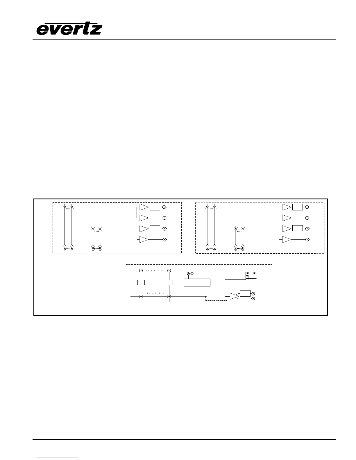
AES 1
Audio Inputs
12
112
Relay Bypass available with bypass option
*
Bypass
Cable
Relay
*
Driver
Protected
Cable
Driver
Bypass
Cable
Relay
*
Driver
Protected
Cable
Driver
AES 1 connections on Breakout panel
1
Included only in AES and AES4 models
112
Video Inputs
EQ EQ
Video Connections on main unit
AES 1A
Outputs
AES 1B
Outputs
Video Ref
Loop
AES 2
Audio Inputs
12
112
Genlock
Reclocker
Reclocker bypass on
HD Routers
1
Control
Cable
Driver
*
Protected
Bypass
Relay
GPI/GPO
RS-422
RS-232
Video Output
Buss 1
AES 2 connections on Breakout panel
Included only in AES4 models
Bypass
Cable
Relay
*
Driver
Protected
Cable
Driver
Bypass
Cable
Relay
*
Driver
Protected
Cable
Driver
AES 2A
Outputs
AES 2B
Outputs
Figure 1-1: X1201 Block Diagram
OVERVIEW
Revision 1.3.2
Page 1-3
X1200 Series Router Manual
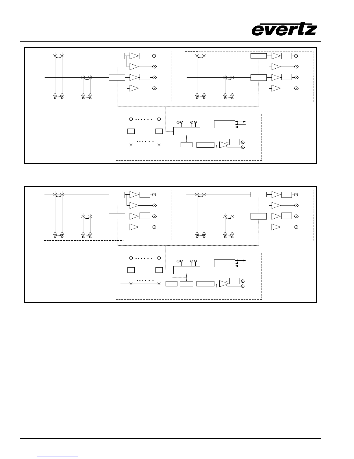
AES 1
Audio Inputs
12
112
Relay Bypass available with bypass option
*
Clean video switching and 'popless' AES switching
#
available with SoftSwitch
options
Audio Inputs
12
112
1
TM
and Embedded SoftSwitch
AES 1
1
Bypass
Cable
TM
TM
AES 1 connections on Breakout panel
Included only in AES and AES4 models
Relay
*
Driver
Protected
Cable
Driver
Bypass
Cable
Relay
*
Driver
Protected
Cable
Driver
112
Video Inputs
EQ EQ
Video Connections on main unit
AES 1A
Outputs
AES 1B
Outputs
Video Ref
Loop
AES 2
Audio Inputs
12
112
DARS Ref
Loop
1
Control
Genlock
Clean
#+
Switch
Reclocker
Reclocker bypass on
HD Routers
*
Protected
Cable
Driver
Bypass
Relay
TM
#
SoftSwitch
#
SoftSwitch
Figure 1-2: X1201 SoftSwitch Block Diagram
#+
#+
SoftSwitch
SoftSwitch
TM
TM
Bypass
Cable
Relay
*
Driver
Protected
Cable
Driver
Bypass
Cable
Relay
*
Driver
Protected
Cable
Driver
AES 1 connections on Breakout panel
Included only in AES and AES4 models
AES 1A
Outputs
AES 1B
Outputs
AES 2
Audio Inputs
12
112
1
#
#
GPI/GPO
RS-422
RS-232
Video Output
Buss 1
#+
#+
SoftSwitch
SoftSwitch
SoftSwitch
SoftSwitch
Driver
Cable
Driver
Cable
TM
Driver
Cable
Driver
AES 2 connections on Breakout panel
Included only in AES4 models
Cable
TM
Driver
Cable
Driver
Cable
TM
Driver
Cable
Driver
AES 2 connections on Breakout panel
Included only in AES4 models
Cable
TM
*
Protected
*
Protected
*
Protected
*
Protected
Bypass
Bypass
Bypass
Bypass
Relay
Relay
Relay
Relay
AES 2A
Outputs
AES 2B
Outputs
AES 2A
Outputs
AES 2B
Outputs
Relay Bypass available with bypass option
*
Clean video switching and 'popless' AES switching
#
available with SoftSwitch
options
Clean video switching and 'popless' AES and
+
embedded audio switching available with Embedded
TM
SoftSwitch
option
TM
and Embedded SoftSwitch
Figure 1-3: X1201 Embedded SoftSwitch Block Diagram
TM
Video Connections on main unit
112
Video Inputs
Video Ref
Loop
EQ EQ
Clean
#+
Switch
Embedded
+
SoftSwitch
Genlock
DARS Ref
Loop
Reclocker
Reclocker bypass on
HD Routers
Control
Cable
Driver
*
Protected
Bypass
GPI/GPO
RS-422
RS-232
Relay
Video Output
Buss 1
Page 1-4
Revision 1.3.2
OVERVIEW
X1200 Series Router Manual
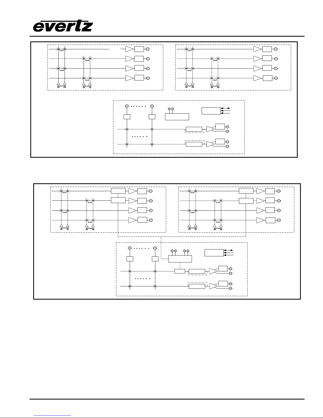
AES 1
Audio Inputs
112
12
Relay Bypass available with bypass option
*
AES 1
Audio Inputs
112
12
Bypass
Cable
Relay
*
Driver
Protected
Bypass
Cable
Relay
*
Driver
Protected
Bypass
Cable
Relay
*
Driver
Protected
Bypass
Cable
Relay
*
Driver
Protected
AES 1 connections on Breakout panel
1
Included only in AES and AES4 models
112
Video Inputs
EQ EQ
AFV1
AES
Outputs
AFV2
AES
Outputs
Video Ref
Loop
AES 2
Audio Inputs
112
12
1
Control
Genlock
Bypass
*
Relay
Protected
Reclocker
Reclocker bypass on
HD Routers
Reclocker
Cable
Driver
Bypass
*
Relay
Protected
Cable
Driver
GPI/GPO
RS-422
RS-232
Video Output
Buss 1
Video Output
Buss 2
Bypass
Cable
Relay
*
Driver
Protected
Bypass
Cable
Relay
*
Driver
Protected
Bypass
Cable
Relay
*
Driver
Protected
Bypass
Cable
Relay
*
Driver
Protected
AES 2 connections on Breakout panel
Included only in AES4 models
AFV1
AES
Outputs
AFV2
AES
Outputs
Video Connections on main unit
Figure 1-4: X1202 Block Diagram
#
TM
SoftSwitch
#
TM
SoftSwitch
1
Bypass
Cable
Relay
*
Driver
Protected
Bypass
Cable
Relay
*
Driver
Protected
Bypass
Cable
Relay
*
Driver
Protected
Bypass
Cable
Relay
*
Driver
Protected
AES 1 connections on Breakout panel
Included only in AES and AES4 models
AFV1
AES
Outputs
AFV2
AES
Outputs
AES 2
Audio Inputs
112
12
1
#
SoftSwitch
#
SoftSwitch
TM
TM
Bypass
Cable
Relay
*
Driver
Protected
Bypass
Cable
Relay
*
Driver
Protected
Bypass
Cable
Relay
*
Driver
Protected
Bypass
Cable
Relay
*
Driver
Protected
AES 2 connections on Breakout panel
Included only in AES4 models
AFV1
AES
Outputs
AFV2
AES
Outputs
Relay Bypass available with bypass option
*
Clean video switching and 'popless' AES switching
#
available with SoftSwitch
options
TM
and Embedded SoftSwitch
Video Ref
112
Video Inputs
Loop
DARS Ref
Loop
Control
#
Genlock
Clean
Switch
Reclocker
Reclocker bypass on
HD Routers
Reclocker
Bypass
*
Relay
Protected
Cable
Driver
Bypass
*
Relay
Protected
Cable
Driver
TM
EQ EQ
Video Connections on main unit
Figure 1-5: X1202 SoftSwitch Block Diagram
GPI/GPO
RS-422
RS-232
Video Output
Buss 1
Video Output
Buss 2
OVERVIEW
Revision 1.3.2
Page 1-5
X1200 Series Router Manual
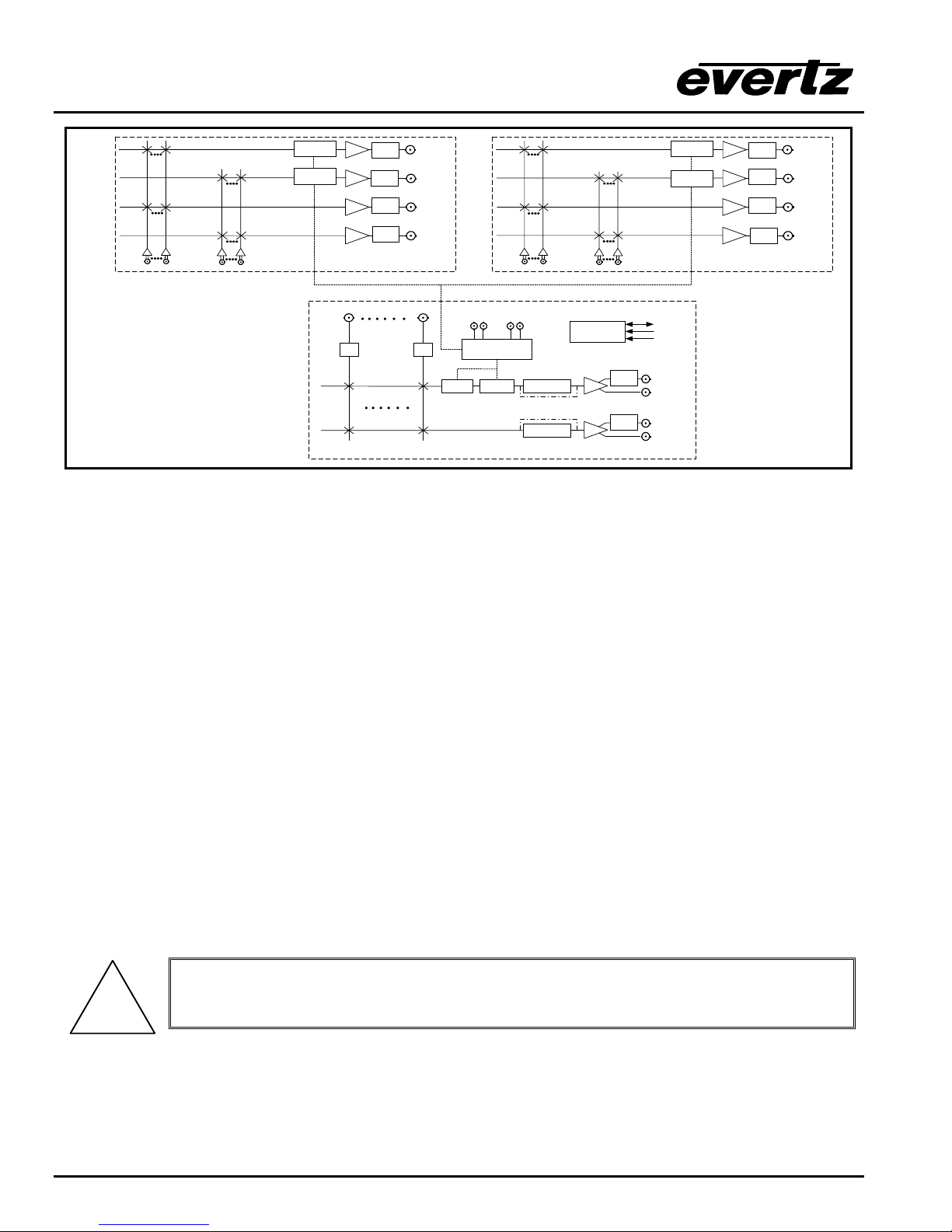
AES 1
Audio Inputs
112
12
Relay Bypass available with bypass option
*
Clean video switching and 'popless' AES switching
#
available with SoftSwitch
options
Clean video switching and 'popless' AES and
+
embedded audio switching available with Embedded
TM
SoftSwitch
option
1
TM
and Embedded SoftSwitch
#+
TM
Cable
SoftSwitch
Driver
#+
TM
Cable
SoftSwitch
Driver
Cable
Driver
Cable
Driver
AES 1 connections on Breakout panel
Included only in AES and AES4 models
112
TM
EQ EQ
Video Connections on main unit
Bypass
Relay
*
Protected
Bypass
Relay
*
Protected
Bypass
Relay
*
Protected
Bypass
Relay
*
Protected
Video Inputs
AFV1
AES
Outputs
AFV2
AES
Outputs
#+
TM
SoftSwitch
#+
TM
SoftSwitch
AES 2
Audio Inputs
112
12
Video Ref
DARS Ref
Loop
Loop
Genlock
#+
Embedded
Clean
Switch
+
SoftSwitch
Reclocker
Reclocker bypass on
HD Routers
Reclocker
1
Control
Cable
Driver
Cable
Driver
*
Protected
*
Protected
Bypass
Bypass
GPI/GPO
RS-422
RS-232
Relay
Video Output
Buss 1
Relay
Video Output
Buss 2
Bypass
Cable
Relay
*
Driver
Protected
Bypass
Cable
Relay
*
Driver
Protected
Bypass
Cable
Relay
*
Driver
Protected
Bypass
Cable
Relay
*
Driver
Protected
AES 2 connections on Breakout panel
Included only in AES4 models
AFV1
AES
Outputs
AFV2
AES
Outputs
Figure 1-6: X1202 Embedded SoftSwitch Block Diagram
1.1. HOW TO USE THIS MANUAL
This manual is organised into 5 chapters: Overview, Installation, Operation, Technical Description, Serial
Protocol, Output Configurations, and System Timing. This chapter contains a quick summary of the router
features and a glossary to define concepts and terms used throughout the remainder of the manual.
Chapter 2 gives a detailed description of the rear panel connectors, and how the router should be
connected into your system.
Chapter 3 gives a detailed description of the operation of the front panel controls, starting with an overview
of the pushbuttons and front panel indicators. The operation of the router using the optional remote
control panel is identical to the front panel.
Chapter 4 gives an overview of how to update the firmware in the unit and other technical issues.
Chapter 5 is a programmer’s reference to the serial control protocol.
Chapter 6 provides a pictorial representation of video and audio output configurations for each version of
the router.
Chapter 7 provides a few video timing examples to aid the system designer in properly timing the router.
Items of special note are indicated with a double box like this.
!
1.2. GLOSSARY
CCIR-601 (This document now known as ITU-R601). An international standard for component digital
television from which was derived SMPTE 125M and EBU 3246-E standards. CCIR-601
Page 1-6
Revision 1.3.2
OVERVIEW

X1200 Series Router Manual
defines the sampling systems, matrix values and filter characteristics for both Y, B-Y, R-Y and
RGB component digital television signals.
SERIAL DIGITAL Digital information that is transmitted in serial form. Often used informally to refer to
serial digital television signals.
4Fsc: Four times subcarrier sampling rate uses in composite digital systems. In NTSC this is 14.3 MHz.
In PAL this is 17.7 MHz.
4:2:2 A commonly used term for a component digital video format. The details of the format are
specified in the CCIR-601 standard. The numerals 4:2:2 denote the ratio of the sampling
frequencies of the luminance channel to the two colour difference channels. For every four
luminance samples, there are two samples of each colour difference channel.
SDI An abbreviation for serial digital interface, this acronym is most commonly used to refer to
Standard definition serial digital television video signals up to 540 Mb/s.
HDTV An abbreviation for high definition television, this acronym is most commonly used to refer to High
definition serial digital television video signals at 1.485 Gb/s.
AES: (Audio Engineering Society): A professional organisation that recommends standards for the
audio industries.
AES/EBU: Informal name for a digital audio standard established jointly by the Audio Engineering
Society and the European Broadcasting Union organisations.
ANALOG: An adjective describing any signal that varies continuously as opposed to a digital signal
that contains discrete levels representing digits 0 and 1.
A-TO-D CONVERTER (ANALOG-TO-DIGITAL): A circuit that uses digital sampling to convert an
analog signal into a digital representation of that signal.
BIT: A binary representation of 0 or 1. One of the quantized levels of a pixel.
BIT PARALLEL: Byte-wise transmission of digital video down a multi-conductor cable where each
pair of wires carries a single bit. This standard is covered under SMPTE 125M, EBU 3267-E
and CCIR 656.
BIT SERIAL: Bit-wise transmission of digital video down a single conductor such as coaxial cable. May
also be sent through fiber optics. This standard is covered under SMPTE 259M and CCIR 656.
BIT STREAM:A continuous series of bits transmitted on a line.
BYTE: A complete set of quantized levels containing all the bits. Bytes consisting of 8 to 10 bits per
sample are typical in digital video systems.
CABLE EQUALIZATION: The process of altering the frequency response of a video amplifier to
compensate for high frequency losses in coaxial cable.
CCIR (International Radio Consultative Committee): An international standards committee. (This
organisation is now known as ITU.)
OVERVIEW
Revision 1.3.2
Page 1-7

X1200 Series Router Manual
CCIR-601: (This document now known as ITU-R601). An international standard for component digital
television from which was derived SMPTE 125M and EBU 3246-E standards. CCIR-601
defines the sampling systems, matrix values and filter characteristics for both Y, B-Y, R-Y and
RGB component digital television signals.
CCIR-656: (This document now known as ITU-R656). The physical parallel and serial interconnect
scheme for CCIR-601. CCIR-656 defines the parallel connector pinouts as well as the
blanking, sync and multiplexing schemes used in both parallel and serial interfaces. It reflects
definitions found in EBU Tech 3267 (for 625 line systems) and SMPTE 125M (parallel 525 line
systems) and SMPTE 259M (serial 525 line systems).
CLIFF EFFECT: (also referred to as the ‘digital cliff’) This is a phenomenon found in digital video systems
that describes the sudden deterioration of picture quality due to excessive bit errors, often
caused by excessive cable lengths. The digital signal will be perfect even though one of its
signal parameters is approaching or passing the specified limits. At a given moment however,
the parameter will reach a point where the data can no longer be interpreted correctly, and the
picture will be totally unrecognisable.
COMPONENT ANALOG: The non-encoded output of a camera, video tape recorder, etc., consisting of
the three primary colour signals: red, green, and blue (RGB) that together convey all necessary
picture information. In some component video formats these three components have been
translated into a luminance signal and two colour difference signals, for example Y, B-Y, R-Y.
COMPONENT DIGITAL: A digital representation of a component analog signal set, most often Y, B-Y,
R-Y. The encoding parameters are specified by CCIR-601. The parallel interface is specified
by CCIR-656 and SMPTE 125M.
COMPOSITE ANALOG: An encoded video signal such as NTSC or PAL video that includes
horizontal and vertical synchronising information.
COMPOSITE DIGITAL: A digitally encoded video signal, such as NTSC or PAL video that includes
horizontal and vertical synchronising information.
D1: A component digital video recording format that uses data conforming to the CCIR-601 standard.
Records on 19 mm magnetic tape. (Often used incorrectly to refer to component digital video.)
D2: A composite digital video recording format that uses data conforming to SMPTE 244M. Records
on 19 mm magnetic tape. (Often used incorrectly to refer to composite digital video.)
D3: A composite digital video recording format that uses data conforming to SMPTE 244M. Records
on 1/2" magnetic tape.
EBU (European Broadcasting Union): An organisation of European broadcasters that among other
activities provides technical recommendations for the 625/50 line television systems.
EBU TECH 3267-E: The EBU recommendation for the parallel interface of 625 line digital video signal.
This is a revision of the earlier EBU Tech 3246-E standard that was in turn derived from CCIR-
601.
EDH: Error Detection and Handling (EDH) is defined in SMPTE RP-165 as a method of determining
when bit errors have occurred along the digital video path. According to RP-165, two error
detection checkwords are used, one for active picture samples, and the other on a full field of
samples. Three sets of flags are used to convey information regarding detected errors, to
Page 1-8
Revision 1.3.2
OVERVIEW

X1200 Series Router Manual
facilitate identification of faulty equipment or cabling. One set of flags is associated with each
checkword, and the third is used to evaluate ancillary data integrity. The checkwords and flags
are combined into a special error detection data packet that is included as ancillary data in the
serial digital signal.
EMBEDDED AUDIO: Digital audio is multiplexed onto a serial digital video data stream.
GVG TEN-XL: A 10 x 1 router made by the Grass Valley Group. The serial control protocol used for this
router has become an industry standard. The control protocol used to control the Evertz 95XX
series routers is an extension of this protocol.
ITU: The United Nations regulatory body governing all forms of communications. ITU-R (previously
CCIR) regulates the radio frequency spectrum, while ITU-T (previously CCITT) deals with the
telecommunications standards.
ITU-R601: See CCIR601
PIXEL:The smallest distinguishable and resolvable area in a video image. A single point on the screen.
In digital video, a single sample of the picture. Derived from the words picture element.
RESOLUTION: The number of bits (four, eight, ten, etc.) determines the resolution of the signal.
Eight bits is the minimum resolution for broadcast television signals.
4 bits = a resolution of 1 in 16.
8 bits = a resolution of 1 in 256.
10 bits = a resolution of 1 in 1024.
SERIAL DIGITAL: Digital information that is transmitted in serial form. Often used informally to refer to
serial digital television signals.
SMPTE (Society of Motion Picture and Television Engineers): A professional organisation that
recommends standards for the film and television industries.
SMPTE 125M: The SMPTE standard for bit parallel digital interface for component video signals.
SMPTE 125M defines the parameters required to generate and distribute component video
signals on a parallel interface.
SMPTE 244M: The SMPTE standard for bit parallel digital interface for composite video signals.
SMPTE 244M defines the parameters required to generate and distribute composite video
signals on a parallel interface.
SMPTE 259M: The SMPTE standard for 525 line serial digital component and composite interfaces.
SMPTE 292M: The SMPTE standard for 1125 line serial digital high definition video interfaces.
SMPTE 299M: The SMPTE standard for embedding AES audio into SMPTE 292M serial digital
high definition video.
SoftSwitch: An Evertz patent pending technology the eliminates audio pops and clicks due to
interruptions of the AES carrier. These interruptions are often caused by non-synchronous
switching of the inputs, or may be present from upstream devices. Embedded SoftSwitch
uses the same technologuy to remove pops and clicks from embedded audio.
OVERVIEW
Revision 1.3.2
Page 1-9

X1200 Series Router Manual
TRS-ID: Abbreviation for "Timing Reference Signal Identification". A reference signal used to
maintain timing in composite digital systems. (It is four words long.)
Page 1-10
Revision 1.3.2
OVERVIEW

X1200 Series Router Manual
CHAPTER 2: INSTALLATION
TABLE OF CONTENTS
2. INSTALLATION................................................................................................................................ 2-1
2.1. REAR PANEL.......................................................................................................................... 2-1
2.1.1. Standard Definition Digital Video Connections (X1200S) ............................................ 2-1
2.1.2. High Definition Digital Video Connections (X1202H) ................................................... 2-1
2.1.3. AES Audio Connections ............................................................................................... 2-2
2.1.3.1. Audio Connections on Router Models with the AES Option Fitted. ............. 2-2
2.1.3.2. Audio Connections On Early Router Models With The AES Option Fitted.
(two breakout panels shipped)..................................................................... 2-2
2.1.3.3. Audio Connections on Router Models with the AES4 Option Fitted. ........... 2-3
2.1.4. Reference Connections................................................................................................ 2-3
2.1.5. Remote Control Connections ....................................................................................... 2-3
2.1.6. Power Connections ...................................................................................................... 2-5
2.2. MOUNTING ............................................................................................................................. 2-5
2.3. POWER REQUIREMENTS...................................................................................................... 2-5
2.3.1. Selecting the Correct Mains Voltage ............................................................................ 2-5
2.3.2. Changing the Fuses ..................................................................................................... 2-6
2.4. CONNECTING THE REMOTE CONTROL PANEL ................................................................ 2-6
2.4.1. Connecting The Primary Remote Control Panel (RCP Version) .................................. 2-6
2.4.2. Connecting A Second Remote Control Panel .............................................................. 2-7
2.5. CONNECTING THE GENERAL PURPOSE INPUTS AND OUTPUTS .................................. 2-7
2.5.1. Connecting the General Purpose Inputs ...................................................................... 2-8
2.5.2. Connecting the General Purpose Outputs ................................................................... 2-9
2.5.3. GPI/O Examples........................................................................................................... 2-9
2.6. CONTROLLING THE ROUTER USING THE EXTERNAL SERIAL PROTOCOL ................ 2-10
2.6.1. Connecting the Router to a Grass Valley Ten XL ASCII Control Device ................... 2-10
Figures
Figure 2-1: X1202H-AES4 Rear Panel Layout...................................................................................... 2-1
Figure 2-2: X1202S-AES4 Rear Panel Layout ...................................................................................... 2-1
Figure 2-3: X1202ABO Audio Breakout Panel Layout .......................................................................... 2-2
Figure 2-4: General Purpose I/O Schematic ......................................................................................... 2-7
Figure 2-5: Powering the General Purpose Input Opto-Isolators from the Router ................................ 2-8
Figure 2-6: Powering the General Purpose Input Opto-Isolators from an External Power Supply........ 2-9
Figure 2-7: GPIO Example – Auto Changeover to Input 2 on Loss of Input 1 .................................... 2-10
INSTALLATION
Revision 1.3.2

X1200 Series Router Manual
Tables
Table 2-1: Router RS-232 Port Pin Definitions...................................................................................... 2-4
Table 2-2: Router RS-422 Port Pin Definitions...................................................................................... 2-4
Table 2-3: GPI/O Pin Definitions ........................................................................................................... 2-5
Table 2-4: Remote Control Panel Extender Cable ................................................................................ 2-6
Table 2-5: Master 1202 to Slave 1202 Cable – RS-232 Configuration ............................................... 2-11
Table 2-6: Master 1202 to Slave 1202 Cable – RS-422 Configuration ............................................... 2-11
Revision 1.3.2
INSTALLATION
X1200 Series Router Manual
2. INSTALLATION
2.1. REAR PANEL
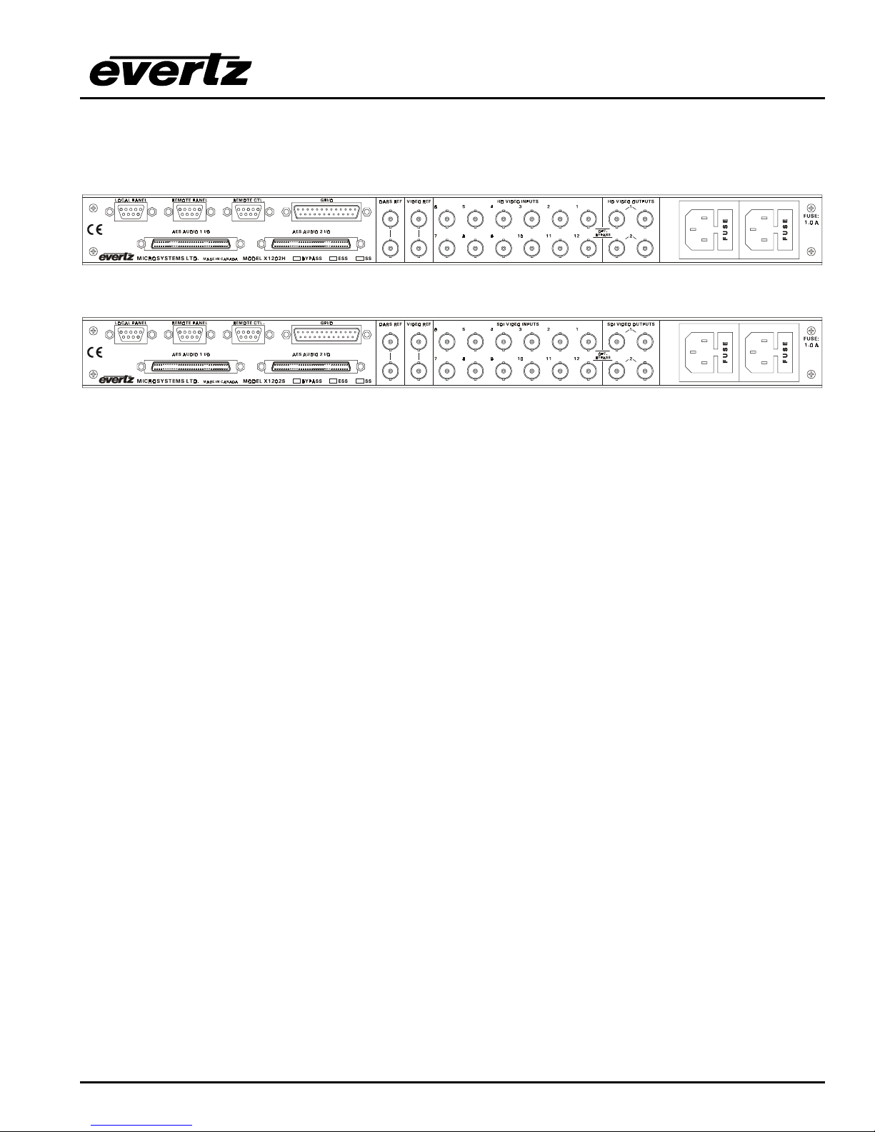
Figure 2-1: X1202H-AES4 Rear Panel Layout
Figure 2-2: X1202S-AES4 Rear Panel Layout
Sections 2.1.1 to 2.1.6 describe the purpose of the rear panel connectors and the specific signals that
should be connected to the routers. Router versions that have SoftSwitch, Embedded SoftSwitch or
Bypass relay options installed will have the option checked (√) on the rear panel. Chapter 6 provides
pictorial representations of the video and audio output configurations for each version of the router.
2.1.1. Standard Definition Digital Video Connections (X1200S)
SDI VIDEO INPUTS 1 to 12 These BNC connectors are for connecting 10-bit serial digital video signals,
compatible with the SMPTE 259M standard to the respective video input buss.
SDI VIDEO OUTPUTS 1 and 2 There are two video output connectors for each of the two video
router busses on X1202S routers. The Video from the selected Video Input buss will be
available on two outputs for each bus. X1201S routers do not have the Second output bus.
When the bypass relay option is fitted, INPUT 1 is protected by a bypass relay to the adjacent
OUTPUT 1 BNC for both X1202S and X1201S routers. INPUT 12 is protected by a bypass
relay to the adjacent OUTPUT 2 BNC on the X1202S routers only. The bypass relays will
activate in the event of power loss to the router and can also be activated from the front panel
menu.
2.1.2. High Definition Digital Video Connections (X1202H)
HD VIDEO INPUTS 1 to 12 These BNC connectors are for connecting 10-bit serial digital video signals,
compatible with the SMPTE 292M standard to the respective video input buss.
HD VIDEO OUTPUTS 1 and 2 There are two video output connectors for each of the two video
router busses. The Video from the selected Video Input buss will be available on two outputs
for each bus.
When the bypass relay option is fitted, INPUT 1 is protected by a bypass relay to the adjacent
OUTPUT 1 BNC and INPUT 12 is protected by a bypass relay to the adjacent OUTPUT 2 BNC.
The bypass relays will activate in the event of power loss to the router and can also be
activated from the front panel menu.
INSTALLATION
Revision 1.3.2
Page 2-1
X1200 Series Router Manual
2.1.3. AES Audio Connections
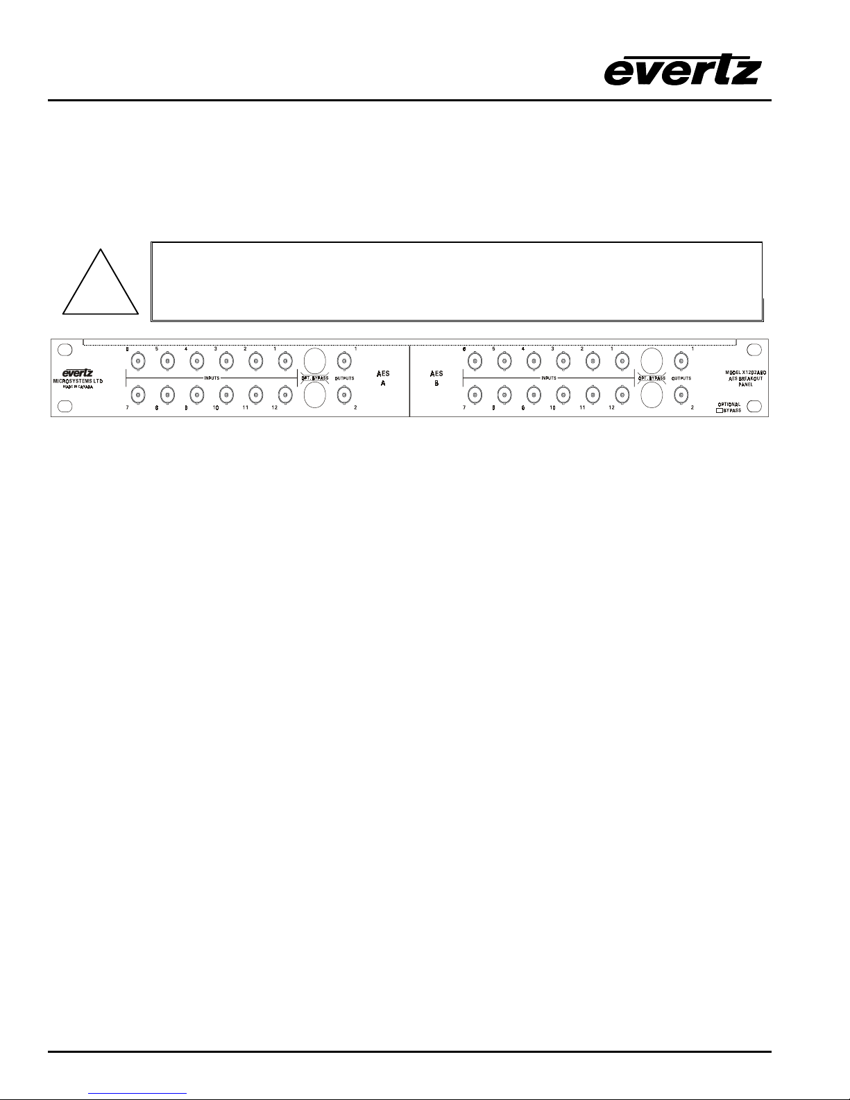
There are two 68 pin connectors used to connect the AES Audio Breakout panels (X1202ABO or
X1201ABO) to the Router. These panels are connected using the cables provided. Each Audio Breakout
Panel has two identical sections consisting of 12 AES inputs and 2 outputs. Earlier versions of the router
may not have either or both audio connectors installed. See sections 2.1.3.1 to 2.1.3.3 for information
about connecting the audio for the version of the router that you have.
When connecting the Audio Breakout Panel cables, insert the cable carefully into
the connector on the router and the breakout panel, being careful not to bend the
!
INPUTS 1 to 12 These BNC connectors are for connecting unbalanced AES audio signals compatible
pins. Press it firmly in place and hand tighten the hold down screws firmly to
provide proper strain relief.
Figure 2-3: X1202ABO Audio Breakout Panel Layout
with the SMPTE 276M standard to the respective audio input buss.
OUTPUTS 1 and 2 These BNC connectors are for connecting unbalanced AES audio signals
compatible with the SMPTE 276M standard from the respective audio input buss.
On the X1202ABO used with the X1202 routers, when the bypass relay option is fitted, INPUT
1 is protected by a bypass relay to the adjacent OUTPUT 1 BNC and INPUT 12 is protected by
a bypass relay to the adjacent OUTPUT 2 BNC. On the X1201ABO used with the X1201
routers, INPUT 1 is protected by a bypass relay to the adjacent OUTPUT 1 BNC. The bypass
relays will activate in the event of power loss to the router and can also be activated from the
front panel menu.
2.1.3.1. Audio Connections on Router Models with the AES Option Fitted.
Routers fitted with the AES option are shipped with one breakout panel. This panel is connected to the
AES AUDIO 1 I/O connector using the cable provided. On the X1202ABO used with the X1202 routers,
inputs for the 1A and 2A busses are on the AES A section of the breakout panel. (See Figure 6-6 and
Figure 6-7) Outputs 1 and 2 of the AES A section are the outputs from the 1A and 2A busses
respectively. Inputs for the 1B and 2B busses are on the AES B section of the breakout panel. Outputs 1
and 2 of the AES B section are the outputs from the 1B and 2B busses respectively. On the X1201ABO
used with the X1201 routers, outputs 1 and 2 are identical. (See Figure 6-2)
2.1.3.2. Audio Connections On Early Router Models With The AES Option Fitted.
(two breakout panels shipped)
Some early versions of the routers with the AES option were shipped with two breakout panels. On these
routers, there are two distinct modes of operation. The AES MODE menu item on the INPUT SETUP
menu is used to select the desired mode.
In the 4(12x1) mode there are four separate 12 x 1-router sections that can be independently assigned to
follow one of the video busses. Routers fitted with the AES option are shipped with one breakout panel.
Page 2-2
Revision 1.3.2
INSTALLATION

X1200 Series Router Manual
Inputs for the 1A and 1B busses are on the panel connected to the AES AUDIO 1 I/O connector. Outputs
1 and 2 of the AES A and AES B sections are identical outputs from the 1A and 1B busses respectively.
Inputs for the 2A and 2B busses are on the panel connected to the AES AUDIO 2 I/O connector. Outputs
1 and 2 of the AES A and AES B sections are identical outputs from the 2A and 2B busses respectively.
(See Figure 6-12 and Figure 6-13)
In the 2(12x2) mode there are two 12 x 2 router sections. The inputs and outputs from the 1A and 1B
busses follow the V1 buss and are located on the on the breakout panel connected to the AES AUDIO 1
I/O connector. The inputs to 2A and 2B audio busses are internally connected to the inputs of the 1A and
1B audio busses respectively (The inputs on the breakout panel connected to the AES AUDIO 2 I/O
connector are not used in this mode). The outputs from the 2A and 2B busses follow the V2 buss and are
located on the on the breakout panel connected to the AES AUDIO 2 I/O connector. (See Figure 6-10 and
Figure 6-11)
2.1.3.3. Audio Connections on Router Models with the AES4 Option Fitted.
Routers fitted with the AES4 option are shipped with two breakout panels. The inputs and outputs from
the 1A and 1B busses and are located on the on the breakout panel connected to the AES AUDIO 1 I/O
connector. The Audio from the selected Audio Input buss associated with video buss 1 will be available
on output 1 of AES A and AES B sections of the breakout panel. On the X1202ABO used with the X1202
routers, audio from the selected Audio Input buss associated with video buss 2 will be available on output
2 of AES A and AES B sections of the breakout panel. (See Figure 6-8 and Figure 6-9) On the
X1201ABO used with the X1201 routers, outputs 1 and 2 are identical. (See Figure 6-3)
The inputs and outputs from the 2A and 2B busses and are located on the on the breakout panel
connected to the AES AUDIO 2 I/O connector. The Audio from the selected Audio Input buss associated
with video buss 1 will be available on output 1 of AES A and AES B sections of the breakout panel. Audio
from the selected Audio Input buss associated with video buss 2 will be available on output 2 of AES A
and AES B sections of the breakout panel. On the X1201ABO used with the X1201 routers, outputs 1 and
2 are identical.
2.1.4. Reference Connections
VIDEO REF is a high impedance loop through for connecting an analog video or tri-level sync (X1200H
series only) reference. The REFERENCE menu is used to select the correct type of video
reference being used.
DARS REF (X1202S-AES-SS and X1202S-AES4-SS only) is a high impedance loop through for a Digital
Audio Reference Signal. The REFERENCE menu is used to select the use of the DARS signal
when the Softswitch is enabled on Softswitch routers.
2.1.5. Remote Control Connections
REMOTE CTL This 9 pin female D connector provides an RS-232 serial interface used for updating the
firmware or external serial remote control. The Setup menu is used to configure the REMOTE
CTL port for external control or firmware updating. (See section 3.3.). This port is wired at the
factory as an RS232 DCE port as shown in Table 2-1.
The port can also be used to connect a remote control panel to the router. To connect to a
remote panel the port must be configured as a SMPTE 207M Tributary as shown in Table 2-2.
To reconfigure the port the user must remove the top cover and reposition jumper J26 so that it
is on pins 2 & 3 (toward header J23) and move the ribbon cable to header J23.
INSTALLATION
Revision 1.3.2
Page 2-3

X1200 Series Router Manual
Pin
Name Description
#
1 GND Chassis ground
2 TxD RS-232 Transmit Output
3 RxD RS-232 Receive Input
4
5 Sig Gnd RS-232 Signal Ground
6
7 RTS RS-232 RTS Input
8 CTS RS-232 CTS Output
9
Table 2-1: Router RS-232 Port Pin Definitions
REMOTE PANEL This 9 pin female D connector provides an RS-422 serial interface used if the local
panel is not attached to the main chassis. This port is wired as a SMPTE 207M Tributary as
shown in Table 2-2.
Pin
Name Description
#
1 GND Chassis ground
2 Tx- RS-422 Tx-(a) Output
3 Rx+ RS-422 Rx+(b) Input
4GND
5
6GND
7 Tx+ RS-422 Tx+(b) Output
8 Rx- RS-422 Rx-(a) Input
9GND
Table 2-2: Router RS-422 Port Pin Definitions
LOCAL PANEL This connector is currently not used.
GPI / O This female DB-25 pin connector provides 14 General Purpose Opto-isolated inputs (GPIs) and
4 General Purpose isolated relay outputs (GPOs). Vint provides +5Volts from the Router and
Vext is used to provide external power the opto isolators. Typically Vint and Vext are
connected together so that the isolators may be powered from the router. Table 2-3 shows the
pin definitions of the GPIO connector. Figure 2-4 shows a schematic of the GPIO circuitry.
See section 2.5 for more information on connecting the General Purpose inputs and outputs.
The functions of the GPIs and GPOs are assigned using the Setup menu, and can be used to
select crosspoints and receive tallies from the router. See section 3.12 and 3.13 for information
on setting up the GPIO operation.
Page 2-4
Revision 1.3.2
INSTALLATION

X1200 Series Router Manual
Pin
Name Description
#
1 GPI 01 General Purpose Input 01
2 GPI 02 General Purpose Input 02
3 GPI 03 General Purpose Input 03
4 GPI 04 General Purpose Input 04
5 GPI 05 General Purpose Input 05
6 GPI 06 General Purpose Input 06
7 GPI 07 General Purpose Input 07
8 GPI 08 General Purpose Input 08
9 GPI 09 General Purpose Input 09
10 GPI 10 General Purpose Input 10
11 GPI 11 General Purpose Input 11
12 GPI 12 General Purpose Input 12
13 GPI 13 General Purpose Input 13
14 GPI 14 General Purpose Input 14
15 Vext External voltage input to power opto isolators
16 Vint Protected +5 volts output from router
17 GPO 01 C General Purpose Output 01 Common contact
18 GPO 01 NC General Purpose Output 01 Normally closed contact
19 GPO 02 C General Purpose Output 02 Common contact
20 GPO 02 NC General Purpose Output 02 Normally closed contact
21 GPO 03 C General Purpose Output 03 Common contact
22 GPO 03 NC General Purpose Output 03 Normally closed contact
23 GPO 04 C General Purpose Output 04 Common contact
24 GPO 04 NC General Purpose Output 04 Normally closed contact
25 GND Router Chassis ground
Table 2-3: GPI/O Pin Definitions
2.1.6. Power Connections
The router has one or two (redundant supply is optional) universal power supplies that operate on either
115 Volt / 60 Hz or 230 Volt / 50 Hz AC.
2.2. MOUNTING
The Router is equipped with rack mounting angles and fits into a standard 19 inch by 1.75 inch by 17.75
inch (483 mm x 45 mm x 451mm) rack space. The mounting angles may be removed if rack mounting is
not desired.
2.3. POWER REQUIREMENTS
2.3.1. Selecting the Correct Mains Voltage
Power requirements are 115 or 230 volts AC at 50 or 60 Hz. The router has a universal power supply that
automatically senses the input voltage. Power should be applied by connecting a 3-wire grounding type
power supply cord to the power entry module on the rear panel. The power cord should be minimum 18
AWG wire size; type SVT marked VW-1, maximum 2.5 m in length. If the router is fitted with the
redundant power supply there will be an additional IEC-320 connector on the rear panel.
INSTALLATION
Revision 1.3.2
Page 2-5
X1200 Series Router Manual
If the router is fitted with dual power supplies, make sure that power is removed
!
The IEC 320 power entry module combines a standard power inlet connector, two 5 x 20 mm fuse holders
and an EMI line filter.
2.3.2. Changing the Fuses
The fuse holder is located inside the power entry module. To change the fuses, pull out the fuse holder
from the power entry module using a small screwdriver. The fuse holder contains two fuses, one for the
line and one for the neutral side of the mains connection. Pull out the blown fuse and place a fuse of the
correct value in its place. Use slo blo (time delay) 5 x 20 mm fuses rated for 250 Volts with a current
rating of 1 amp. Carefully reinsert the fuse holder into the power entry module.
from both supplies before performing any work on the unit.
Never replace with a fuse of greater value.
!
2.4. CONNECTING THE REMOTE CONTROL PANEL
The X1200 series routers can be sold with integrated front panel control, or with a rack mountable remote
control panel (RCP version). On the RCP version, the front panel of the main unit has only the PSU
Status indicators. A second control panel (model X1202-REMOTE) can be added to either version.
2.4.1. Connecting The Primary Remote Control Panel (RCP Version)
On the RCP version of the router, the primary control panel is connected to the REMOTE PANEL
connector using a straight through cable provided. For longer distances, simply make your own cable of
the required length according to the diagram in Table 2-4. Communications to the remote panel is through
a standard straight through RS-422 connection, so the panel can be located up to 1000 feet from the main
electronics unit. A plug in 12 VDC adapter supplies power for the remote control panel.
Router End Remote Panel End
9 pin D
Male
Tx- 2 -------1a------ Rx- 2
Rx+ 3 -------2b------ Tx+ 3
Rx Gnd 4 ---drain 2---- Rx Gnd 4
Tx Gnd 6 ---drain 1---- Tx Gnd 6
Tx+ 7 -------1b----- Rx+ 7
Rx- 8 -------2a------ Tx- 8
Frame Gnd Shield ---drain 1---- Frame Gnd Shield
Pin Belden
9729
11
5
99
9 pin D
Female
Pin
Table 2-4: Remote Control Panel Extender Cable
Page 2-6
Revision 1.3.2
INSTALLATION
 Loading...