

evertz hd9084 Instruction Manual

USO RESTRITO
Model HD9084
HD/SD DTV Caption Encoder
Instruction Manual
© Copyright 2002 - 2013
EVERTZ MICROSYSTEMS LTD.
5288 John Lucas Drive,
Burlington, Ontario,
Canada, L7L 5Z9
Phone: 905-335-3700
Tech Support: 905-335-7570
Fax: 905-335-3573
Sales:
Tech Support:
Web Page: http://www.evertz.com
Version 1.20, November 2013
The material contained in this manual consists of information that is the property of Evertz
Microsystems and is intended solely for the use of purchasers of the HD9084 Caption Encoder. E vertz
Microsystems expressly prohibits the use of this manual for any purpose other than the operation of the
HD9084 caption encoder.
All rights reserved. No part of this publication may be reproduced without the express written
permission of Evertz Microsystems Ltd. Copies of this guide can be ordered from your Evertz products
dealer or from Evertz Microsystems.
sales@evertz.com
service@evertz.com

USO RESTRITO
This page left intentionally blank

The lightning flash with arrowhead symbol within an equilateral triangle is
WARNING
XPOSE THIS
APPARATUS TO RAIN OR MOISTURE
WARNING
DO NOT EXPOSE THIS EQUIPMENT TO DRIPPING OR SPLASHING AND ENSURE THAT
NO OBJECTS FILLED WITH LIQUIDS, SUCH AS VASES, ARE PLACED ON THE
EQUIPMENT
WARNING
MAINS, DISCONNECT
THE POWER SUPPLY CORD PLUG FROM THE AC RECEPTACLE
WARNING
THE MAINS PLUG OF THE POWER SUPPLY CORD SHALL REMAIN READILY OPERABLE
USO RESTRITO
IMPORTANT SAFETY INSTRUCTI ONS
intended to alert the user to the presence of uninsulated “Dangerous voltage”
within the product’s enclosure that may be of sufficient mag nitude to constitute a
risk of electric shock to persons.
The exclamation point within an equilateral triangle is intended to alert the user
to the presence of important operating and maintenance (Servicing) instructions
in the literature accompanying the product.
• Read and keep these instructions
• Heed all warnings.
• Follow all instructions.
• Do not use this apparatus near water
• Clean only with dry cloth.
• Do not block any ventilation openings. Install in accordance with the manufacturer’s instructions.
• Do not install near any heat sources such as radiators, heat registers, stoves, or other apparatus
(including amplifiers) that produce heat.
• Do not defeat the safety purpose of the polarized or groundi ng-type plug. A polarized plug has t wo
blades with one wider than other. A grounding-type plug has two blades and a third grounding
prong. The wide blade or the third prong is provided for your safety. If the provided plug does not
fit into your outlet, consult an electrician for replacement of the obsolete outlet.
• Protect the power cord from being walked on or pinched particularly at plugs, convenience
receptacles and the point where they exit from the apparatus.
• Only use attachments/accessories specified by the manufacturer
• Unplug this apparatus during lightning storms or when unused for long periods of time.
• Refer all servicing to qualified service personnel. Servicing is required when the apparatus has
been damaged in any way, such as power-supply cord or p lug is damaged, liquid has been spill ed
or objects have fallen into the apparatus, the apparatus has been exposed to rain or moisture, does
not operate normally, or has been dropped.
TO REDUCE THE RISK OF FIRE OR ELECTRIC – SHOCK, DO NOT E
TO COMPLETELY DISCONNECT THIS EQ UIPMENT FROM THE AC

USO RESTRITO
INFORMATION TO USERS IN EUROP E
NOTE
This equipment with the CE marking complies with bother the EMC Directive (89/336/EEC) and the
Low Voltage Directive (73/23/EEC) issued by the Commission of the European Community.
Compliance with these directives implies conformity to the following European standards:
• EN60065 Product Safety
• EN55103-1 Electromagnetic Interference Class A (Emission)
• EN55103-2 Electromagnetic Susceptibility (Immunity)
This equipment has been tested and found to comply with the limits for a Class A digital device,
pursuant to the European Union EMC directive. These limits are designed to provide reasonable
protection against harmful interference when the equipment is operated in a commer cial environment.
This equipment generates, uses, and can radiate radio frequency energy and, if not installed and used
in accordance with the instruction manual, may cause harmful interference to radio communications.
Operation of this equipment in a residential area is likely to cause harmful interference in which case
the user will be required to correct the interference at his own expense.
INFORMATION TO USERS IN THE U.S.A.
NOTE
FCC CLASS A DIGITAL DEVICE OR PERIPHERAL
This equipment has been tested and found to comply with the limits for a Class A digital device,
pursuant to Part 15 of the FCC Rules. These limits are designed to provide reasonable protection
against harmful interference when the equipment is operated in a commercial environment. This
equipment generates, uses, and can radiate radio frequency energy and, if not installed and used in
accordance with the instruction manual, may cause harmful interference to radio communications.
Operation of this equipment in a residential area is likely to cause harmful interference in which case
the user will be required to correct the interference at his own expense.
WARNING
Changes or Modifications not expressly approved by Evertz Microsystems Ltd. could void the user’s
authority to operate the equipment.
Use of unshielded plugs or cables may cause radiation interference. Properly shielded interface cables
with the shield connected to the chassis ground of the device must be used.

USO RESTRITO
NOTICE TO MODEM USERS IN THE USA
NOTE
The HD9084 Caption Encoder complies with the FCC Rules Part 68. The caption encoder is desi gned
to be used on standard device telephone lines. It connects to the telephone line by means of a
standard jack called the USOC RJ11C and should be connected to the telephone network with a FCC
compliant telephone cord and modular plug.
It is not necessary to notify the telephone company before connecting the modem in the caption
encoder. However, the telephone company may request the telephone number to which the caption
encoder modem is connected and the FCC registration number and ringer equivalence number (REN),
both of which are on the label on the rear panel.
The REN is used to determine the number of devices you may legally connect to your telephone line.
In most areas, the sum of the REN of all devices connected to one line must not exceed five (5.0). You
should contact your telephone company to determine the maximum REN for your calling area.
The caption encoder may not be used on coin service provided by the telephone company. Connection
to party lines is subject to state tariffs.
If the modem in the caption encoder is malfunctioning, it may affect the telephone lines. In this case,
disconnect the modem until the source of the difficulty is traced.
IMPORTANT INSTALLATION NOTI CE
FOR A RELIABLE TELEPHONE CONNECTI ON TO THE MODEM IN THIS CAPTION ENCODER A
DIRECT TELEPHONE LINE MUST BE USED. THIS LINE MUST NOT PASS THRO UGH A PBX OR
SIMILAR KEY DEVICE.

USO RESTRITO
This page left intentionally blank

USO RESTRITO
HD9084 HDTV Caption Encoder Manual
REVISION HISTORY
REVISION DESCRIPTION DATE
0.1 Preliminary Version Sep 2002
0.2 Revised Preliminary versions Oct 2002
1.3 First Release version Jan 2003
1.4 Revised Edition Jun 2003
1.5 Revised Edition Dec 2003
1.8 Revised Edition Feb 2004
1.9 Updated menu structure, 708 Services Dec 2005
1.9.1 Added information on changing battery, reformatting. Aug 2006
1.12. Revised Edition. Updated functionality and feature description. Feb 2007
1.12.1 Changed pinout for RS-422 Tributary Serial Port, added to features Jan 2008
1.12.2 Removed information regarding Down Convert capabilities
and references to SDI Input Source Oct 2008
1.12.3 Updated Composite Monitoring Output information Oct 2008
1.12.4 Added information regarding the GPI Message Inject feature Feb 2009
1.12.5 Updated section 3.5.1. Removed Fault/Status information. Jun 2009
1.12.6 Made changes to section 4.3.2 regarding Reset Encoder control. Jul 2009
1.14 Updates throughout section 3 and 5.
Updated FAQ section and Glossary.
Updated Real Time State description. Oct 2009
1.15 Added items to GPO 1 to 4 Stimulus list. Mar 2010
1.15.1 Updated power and safety electrical specifications Apr 2010
1.16 Updated rear plate drawing in section 2.1 Jun 2010
1.17 Removed reference to Appendix A in section 4.5.2
Added reference to the CEA-608 standard Jun 2010
1.18 Updated common commands throughout section 4 & 6 Apr 2011
REVISION HISTORY

USO RESTRITO
HD9084 HDTV Caption Encoder Manual
1.19 Updated “SD - HD Translator” section Oct 2012
1.20 Major update, primarily chapters 3 & 6 Nov 2013
Information contained in this manual is believed t o be acc urate and reliable. However, Evertz assumes no responsibility for the use t hereof nor
for the rights of third parties, which may be affected in any way by the use thereof. Any representations in this document concerning
performance of Evertz products are for informational use only and are not warranties of f uture performance, either expressed or implied. The
only warranty offered by Evertz in relation to this product is the Evertz standard limited warranty, stated in the sales contract or order
confirmation form.
Although every attempt has been made to accurately describe the features, installation and operation of this product in this manual, no
warranty is granted nor liability assumed i n relation to any errors or omissions unless s pecifically undertaken in the Evertz sales c ontract or
order confirmation. Information contained in t his manual is periodi cally updated and c hanges will be inc orporated int o subs equent editions. If
you encounter an error, please notify Evertz Customer Service department. Evertz reserves the right, without notice or liability, to make
changes in equipment design or specifications.
REVISION HISTORY

USO RESTRITO
HD9084 HDTV Caption Encoder Manual
TABLE OF CONTENTS
OVERVIEW ................................................................................................ 1-1
1.
1.1. HOW TO USE THIS MANUAL ................................................................................................. 1-1
2. INSTALLATION .......................................................................................... 2-1
2.1. Rear Panel ............................................................................................................................... 2-1
2.1.1. Program Video Inputs (PGM IN) ........................................................................................ 2-1
2.1.1.1. SD SDI ....................................................................................................................... 2-1
2.1.1.2. HD SDI ....................................................................................................................... 2-1
2.1.2. Program Video Outputs (PGM OUT).................................................................................. 2-1
2.1.2.1. SD SDI ....................................................................................................................... 2-1
2.1.2.2. HD SDI ....................................................................................................................... 2-1
2.1.3. Monitor Video Output (MON OUT) ..................................................................................... 2-2
2.1.3.1. COMP ........................................................................................................................ 2-2
2.1.3.2. HD SDI ....................................................................................................................... 2-2
2.1.4. Serial Remote Ports ........................................................................................................... 2-2
2.1.4.1. Port A ......................................................................................................................... 2-2
2.1.4.2. Port B ......................................................................................................................... 2-2
2.1.4.3. Port C ......................................................................................................................... 2-3
2.1.4.4. Configuring Ports for RS-232 ...................................................................................... 2-3
2.1.4.5. Configuring Ports for RS-422 ...................................................................................... 2-4
2.1.5. Modems ............................................................................................................................. 2-6
2.1.6. Parallel I/O- DB15 Parallel I/O Connector .......................................................................... 2-6
2.1.7. Power Supply .................................................................................................................... 2-6
2.2. Mounting ................................................................................................................................. 2-6
2.3. Parallel Remote Control Connections ................................................................................... 2-6
4. G PI/O Setup ............................................................................................................................. 2-7
2.
2.5. Typical HD9084 Configurations ............................................................................................. 2-8
3. OPERATION............................................................................................... 3-5
3.1. Fr ont Panel Controls .............................................................................................................. 3-5
3.1.1. Display Panel ..................................................................................................................... 3-5
3.1.2. HD Keyer On/Off ............................................................................................................... 3-5
3.1.3. SD Keyer On/Off ................................................................................................................ 3-5
3.1.4. SHIFT () .......................................................................................................................... 3-5
3.1.5. HD/SD Bypass Relays ....................................................................................................... 3-5
3.1.6. PANEL LOCK .................................................................................................................... 3-6
3.1.7. SETUP .............................................................................................................................. 3-6
3.1.8. Up Arrow () and Down Arrow () ................................................................................... 3-6
3.1.9. SELECT ............................................................................................................................ 3-6
3.1.10. VIDEO ............................................................................................................................ 3-6
TABLE OF CONTENTS

USO RESTRITO
HD9084 HDTV Caption Encoder Manual
3.1.11. DECODE ....................................................................................................................... 3-6
3.1.12. PORTS .......................................................................................................................... 3-6
3.1.13. TIME .............................................................................................................................. 3-7
3.1.14. GENERAL ...................................................................................................................... 3-7
3.1.15. PSU STATUS 1 LED ...................................................................................................... 3-7
3.1.16. PSU STATUS 2 LED (Optional Redundant Power Supply) ............................................ 3-7
3.1.17. Video/Data in HD LED ................................................................................................... 3-7
3.1.18. Video/Data in SD LED .................................................................................................... 3-7
3.1.19. Bypass Relay HD LED ................................................................................................... 3-7
3.1.20. Bypass Relay SD LED ................................................................................................... 3-7
3.1.21. MENU LED .................................................................................................................... 3-8
3.1.22. COMM LED.................................................................................................................... 3-8
3.1.23. SD FLD 1 LED ............................................................................................................... 3-8
3.1.24. SD FLD 2 LED ............................................................................................................... 3-8
3.1.25. HD ANC LED ................................................................................................................. 3-8
3.1.26. FAULT LED.................................................................................................................... 3-8
3.2. Fr ont Panel Displays .............................................................................................................. 3-9
3.2.1. Video Display .................................................................................................................... 3-9
3.2.2. Decode Display ................................................................................................................. 3-9
3.2.3. Ports Display ................................................................................................................... 3-11
3.2.4. Time Display .................................................................................................................... 3-11
3.2.5. General Display ............................................................................................................... 3-12
3.2.5.1. Modem D or Modem E Cycling ................................................................................. 3-13
3.3. Menu Overview ..................................................................................................................... 3-14
4. Video Setup Menu................................................................................................................. 3-15
3.
3.4.1. Video Setup ..................................................................................................................... 3-16
3.4.1.1. HD Video Std ............................................................................................................ 3-16
3.4.1.2. SD Video Std ............................................................................................................ 3-17
3.4.2. SD Captions/ VA NC ......................................................................................................... 3-17
3.4.2.1. NTSC Line Select ..................................................................................................... 3-17
3.4.2.2. PAL Line Select ........................................................................................................ 3-17
3.4.2.3. Field 1 Keyer ............................................................................................................ 3-17
3.4.2.4. Field 2 Keyer ............................................................................................................ 3-17
3.4.2.5. Setup Shift ................................................................................................................ 3-17
3.4.2.6. CEA-608 Test Msg ................................................................................................... 3-18
3.4.2.7. VANC CC Line Sel ................................................................................................... 3-18
3.4.2.8. VANC Keyer Ctrl....................................................................................................... 3-18
3.4.2.8.1. VANC Packets in SD-SDI ..................................................................................... 3-18
3.4.2.9. CC Erase Timer ........................................................................................................ 3-19
3.4.3. HD Captions/VANC ......................................................................................................... 3-19
3.4.3.1. VANC CC Line Sel ................................................................................................... 3-19
3.4.3.2. VANC Keyer Ctrl....................................................................................................... 3-20
3.4.3.3. Service Info Encode ................................................................................................. 3-20
3.4.3.4. Swap F1/F2 Order .................................................................................................... 3-20
3.4.3.5. CEA-708 Test Msg ................................................................................................... 3-20
3.4.3.6. VANC Dolby Line ...................................................................................................... 3-21
3.4.3.7. VANC Dolby DID ...................................................................................................... 3-21
3.4.3.8. Broadcast Flag Packet Insert .................................................................................... 3-21
4.3.9. VANC Scrubber ........................................................................................................ 3-21
3.
TABLE OF CONTENTS

USO RESTRITO
HD9084 HDTV Caption Encoder Manual
3.4.4. Upstream Caps ................................................................................................................ 3-21
3.4.4.1. No Input Source ........................................................................................................ 3-22
3.4.4.2. HD-SDI Input SRC .................................................................................................... 3-22
3.4.4.3. SD-SDI Input SRC .................................................................................................... 3-22
3.4.4.4. Pass Upstream ......................................................................................................... 3-22
3.4.5. SD - HD Translator .......................................................................................................... 3-23
3.4.5.1. Master Control .......................................................................................................... 3-23
3.4.6. Service Info Setup ........................................................................................................... 3-23
3.4.6.1. Service Enable ......................................................................................................... 3-23
3.4.6.2. Set Service Flags ..................................................................................................... 3-23
3.4.6.3. Set Language ........................................................................................................... 3-24
3.5. Decode Setup Menu ............................................................................................................. 3-24
3.5.1. OSD Display Mode .......................................................................................................... 3-24
3.5.2. OSD Transparency .......................................................................................................... 3-25
3.5.3. 608 Decoder .................................................................................................................... 3-25
3.5.3.1. CC Channel .............................................................................................................. 3-25
3.5.3.2. Text Channel ............................................................................................................ 3-25
3.5.3.3. Text Win Top Row .................................................................................................... 3-25
3.5.3.4. Text Win Height ........................................................................................................ 3-25
3.5.3.5. XDS Display ............................................................................................................. 3-26
3.5.3.6. XDS Win Top Row .................................................................................................... 3-26
3.5.3.7. XDS Win Height ........................................................................................................ 3-26
3.5.4. 708 Decoder .................................................................................................................... 3-26
3.5.5. PVR Data Block ............................................................................................................... 3-27
6. Ports Setup Menu ................................................................................................................. 3-28
3.
3.6.1. Port x Setup (x= A,B,C,D,E,F) ......................................................................................... 3-29
3.6.1.1. Port x Mode .............................................................................................................. 3-29
3.6.1.2. Port x Baud ............................................................................................................... 3-30
3.6.1.3. Port x Comms ........................................................................................................... 3-30
3.6.1.4. Port x Enable ............................................................................................................ 3-30
3.6.1.5. Port x Rings .............................................................................................................. 3-30
3.6.1.6. Inactive Timeout (Port F only) ................................................................................... 3-30
3.6.1.7. Telnet Login Enable (Port F only) ............................................................................. 3-30
3.6.1.8. Set Telnet Login (Port F only) ................................................................................... 3-31
3.6.1.9. Set Telnet Password (Port F only) ............................................................................ 3-31
3.6.2. Port x Permissions (x= A,B,C,D,E,F) ............................................................................... 3-31
3.6.2.1. Set All Services ........................................................................................................ 3-31
3.6.2.2. Service # (1-63, CC1-4, T1-4, XDS) ......................................................................... 3-31
3.6.3. GPI Active LVLS .............................................................................................................. 3-31
3.6.3.1. GPI x Active Level (x= A,B,C,D,E,F,G) ..................................................................... 3-31
3.6.4. GPI Caption Shift ............................................................................................................. 3-31
3.6.5. GPI Shift Lines ................................................................................................................. 3-32
3.6.6. Modem Speaker .............................................................................................................. 3-32
3.6.7. GPI/O Config ................................................................................................................... 3-32
3.6.7.1. GPO 1 to 4 Active Lvl ............................................................................................... 3-32
3.6.7.2. GPO 1 to 4 Assert Delay .......................................................................................... 3-32
3.6.7.3. GPO 1 to 4 Deassert Delay ...................................................................................... 3-32
3.6.7.4. GPO 1 to 4 Stimulus ................................................................................................. 3-33
7. Time Setup Menu .................................................................................................................. 3-33
3.
TABLE OF CONTENTS

USO RESTRITO
HD9084 HDTV Caption Encoder Manual
3.7.1. Set UTC Time .................................................................................................................. 3-34
3.7.1.1. Daylight Saving Time Explained ............................................................................... 3-35
3.7.2. LTC Reader Option ......................................................................................................... 3-35
3.7.3. CDP Time Encode ........................................................................................................... 3-35
3.8. General Setup Menu ............................................................................................................. 3-36
3.8.1. Load Preset ..................................................................................................................... 3-37
3.8.2. Store Preset .................................................................................................................... 3-37
3.8.3. Factory Reset .................................................................................................................. 3-37
3.8.4. Erase NV XDS ................................................................................................................. 3-37
3.8.5. Network Setup ................................................................................................................. 3-37
3.8.5.1. IP Address Source .................................................................................................... 3-38
3.8.5.2. Static Address .......................................................................................................... 3-38
3.8.5.3. Static Netmask ......................................................................................................... 3-38
3.8.5.4. Static Broadcast ....................................................................................................... 3-38
3.8.5.5. Static Gateway ......................................................................................................... 3-38
3.8.6. Info Msg Setup ................................................................................................................ 3-39
3.8.6.1. Critical errs ............................................................................................................... 3-39
3.8.6.2. Show ALL errs .......................................................................................................... 3-39
3.8.6.3. Info Msg Only ........................................................................................................... 3-39
3.8.7. Upgrade Firmware ........................................................................................................... 3-39
3.9. Fr ont Panel Informative Messages ...................................................................................... 3-40
3.9.1. Control-A Protocol Fault Messages ................................................................................. 3-40
3.9.2. SMPTE-333 Protocol Fault Messages ............................................................................. 3-40
3.9.3. Caption Distribution Packet (CDP) Fault Messages ......................................................... 3-40
9.4. I nput Caption Fault Messages ......................................................................................... 3-41
3.
3.9.5. Serial Port Fault Messages .............................................................................................. 3-41
3.9.6. Dolby Metadata Fault Messages...................................................................................... 3-42
3.9.7. System Fault Messages .................................................................................................. 3-42
4. CONTROL-A SERIAL PROTOCOL ............................................................4-1
4.1. COMMAND QUICK REFERENCE ........................................................................................... 4-1
4.2. CO MMAND SYNTAX DESCRIPTION ...................................................................................... 4-2
4.2.1. Special Characters ............................................................................................................ 4-2
4.2.2. Parameters ........................................................................................................................ 4-3
4.2.3. Flow Control Handshaking ................................................................................................. 4-5
4.2.4. Break Handling .................................................................................................................. 4-5
4.2.5. Command Responses ....................................................................................................... 4-5
4.3. Comm on Commands .............................................................................................................. 4-5
4.3.1. Set Baud Rate ................................................................................................................... 4-5
4.3.2. Reset Encoder ................................................................................................................... 4-7
4.3.3. Set Output Line .................................................................................................................. 4-7
4.3.4. Monitoring Line 21 Data on the Serial Port ........................................................................ 4-7
4.3.5. Controlling the Caption Decoder ........................................................................................ 4-7
4.3.6. Report Firmware Version ................................................................................................... 4-8
4.3.7. Command Help .................................................................................................................. 4-8
4.3.8. Report Bypass Switch Mode .............................................................................................. 4-8
TABLE OF CONTENTS

USO RESTRITO
HD9084 HDTV Caption Encoder Manual
4.3.9. Report Battery Status ........................................................................................................ 4-8
4.3.10. Set / Report Time of Day Clock ...................................................................................... 4-9
4.3.11. Set / Report Calendar Date .......................................................................................... 4-10
4.3.12. Transparent State ........................................................................................................ 4-10
4.3.13. Null Stat e ..................................................................................................................... 4-10
4.3.14. Direct Control State ...................................................................................................... 4-11
4.3.15. Real Tim e St ate ........................................................................................................... 4-12
4.3.16. Display Syst em Status ................................................................................................. 4-13
4.4. TE XT AR TIC LES .................................................................................................................... 4-13
4.4.1. Input Article...................................................................................................................... 4-13
4.4.2. Output Article ................................................................................................................... 4-14
4.4.3. Delete Article ................................................................................................................... 4-15
4.4.4. Queue Articles ................................................................................................................. 4-15
4.4.5. Display Article Status ....................................................................................................... 4-16
4.4.6. Display Output Queue ..................................................................................................... 4-16
4.5. EXTENDED DATA SERVICES .............................................................................................. 4-17
4.5.1. Input XDS Article ............................................................................................................. 4-17
4.5.2. Blocking Upstream XDS Packets ..................................................................................... 4-18
4.5.3. Queue XDS Packets ........................................................................................................ 4-19
4.5.4. Delete XDS Packet .......................................................................................................... 4-19
4.5.5. Inserting XDS Articles into Non-Volatile Memory ............................................................. 4-19
4.6. COMM PORT CONTROL COMMANDS ................................................................................. 4-19
4.6.1. Show Port Permission Maps ............................................................................................ 4-20
4.6.2. Alter Port Permission Maps ............................................................................................. 4-20
4.6.3. S
4.6.4. Alter Port Active Maps ..................................................................................................... 4-21
4.6.5. Reset Port ....................................................................................................................... 4-22
4.7. G PI Message Inject ............................................................................................................... 4-22
4.7.1. Managing Message Text.................................................................................................. 4-22
4.7.2. Activating Message Inject ................................................................................................ 4-22
4.7.3. Application Tips ............................................................................................................... 4-23
how Port Active Maps .................................................................................................... 4-21
5. TECHNICAL DESCRIPTION ...................................................................... 5-1
5.1. Specifications ......................................................................................................................... 5-1
5.1.1. HDTV Serial Digital Video Input ......................................................................................... 5-1
5.1.2. HDTV Serial Digital Video Output ...................................................................................... 5-1
5.1.3. SDTV Serial Digital Video Input ......................................................................................... 5-1
5.1.4. SDTV Serial Digital Video Output ...................................................................................... 5-1
5.1.5. General Purpose In/Out ..................................................................................................... 5-2
5.1.6. Communications and Control ............................................................................................. 5-2
5.1.7. Physical ............................................................................................................................. 5-2
5.1.8. Electrical ............................................................................................................................ 5-2
5.2. UPDATING THE HD9084 FIRMWARE .................................................................................... 5-3
5.2.1. PART 1: Configuring the Unit for Firmware Upgrades ........................................................ 5-3
5.2.2. PART 2: Terminal Program Setup ..................................................................................... 5-3
TABLE OF CONTENTS

USO RESTRITO
HD9084 HDTV Caption Encoder Manual
5.2.3. PART 3: Initiating Upgrade Mode ...................................................................................... 5-3
5.2.3.1. Front Panel Upgrade Procedure ................................................................................. 5-3
5.2.3.2. Power Cycle Upgrade Procedure ............................................................................... 5-4
5.2.4. PART 4: Uploading the New Firmware .............................................................................. 5-4
5.2.5. PART 5: Completing the Upgrade...................................................................................... 5-4
5.2.5.1. Front Panel Complete Upgrade .................................................................................. 5-4
5.2.5.2. Power Cycle Complete Upgrade ................................................................................. 5-5
5.3. SERVICING INSTRUCTIONS .................................................................................................. 5-5
5.3.1. Changing the Fuses........................................................................................................... 5-5
5.3.2. Replacing the Battery ........................................................................................................ 5-5
5.3.2.1. Safety Guidelines and Precautions concerning the Use of 3V Lithium Batteries ......... 5-6
5.3.2.2. Procedure for Replacing the Battery ........................................................................... 5-6
6. CONFIGURATION AND TROUBLESHOOTING .........................................6-1
6.1. Typical Configuration Examples ........................................................................................... 6-1
6.2. Parallel GPI/O Port Example Applications ............................................................................ 6-2
6.2.1. Automatic Upstream Caption Source Selection (defaults to HD-SDI) ................................. 6-2
6.2.2. Automatic Upstream Caption Source Selection (defaults to SD-SDI) ................................. 6-2
6.2.3. Disabling Teleprompter On Either Modem Or Telnet Connection ...................................... 6-3
6.3. Answers to frequently asked questions ............................................................................... 6-4
6.3.1. Can the HD9084 correct “illegal” captions? ........................................................................ 6-4
6.3.2. Which Serial Port Should I Connect To? ............................................................................ 6-4
6.3.3. There i s No SD-SDI Video Present on the SD-SDI Output ................................................ 6-4
6.3.4. There is No HD-SDI Video Present on the HD-SDI Output ................................................ 6-5
6.3.5. How Do I Check if Captions are Being Processed? ........................................................... 6-5
6.3.5.1. Control-A Protocol Test Using a Terminal P rogram .................................................... 6-5
6.
3.5.2. Composite Monitoring Output Check .......................................................................... 6-6
6.3.6. There are No Captions Present Out of the ATSC Encoder ................................................ 6-6
6.3.7. What Baud Rate and Port Settings Should I Use? ............................................................. 6-7
6.3.8. How Do I Check the Logic Levels and Pinouts of the Serial Ports? .................................... 6-7
6.3.9. How Do I Check the Status of My Power Supplies? ........................................................... 6-7
6.3.10. Captions are not Being Encoded at All ........................................................................... 6-7
6.3.11. Captions are not Being Encoded Correctly ..................................................................... 6-8
6.3.12. How Can I Block Upstream Captions? ........................................................................... 6-8
6.3.13. How Can I Pass Upstream Captions? ............................................................................ 6-8
6.3.14. When Should I Use “Reset to Factory Defaults?” ........................................................... 6-8
6.3.15. My Modem Connection Hangs-Up Unexpectedly ........................................................... 6-9
6.4. Befor e You Call Evertz Technical Support............................................................................ 6-9
7. GLOSSARY ................................................................................................7-1
7.1. G lossary of Standards ........................................................................................................... 7-1
7.2. GLOSSARY OF TERMS .......................................................................................................... 7-2
TABLE OF CONTENTS

USO RESTRITO
HD9084 HDTV Caption Encoder Manual
Figures
Figure 2-1: Rear Panel of HD9084 .............................................................................................. 2-1
Figure 2-2: Wiring RS-232 DTE Serial Port to Computer ............................................................ 2-3
Figure 2-3: RS-232 Configuration ............................................................................................... 2-4
Figure 2-4: Wiring RS-422 Tributary Serial Port to RS-422 Master ............................................. 2-5
Figure 2-5: RS-422 Configuration ............................................................................................... 2-5
Figure 2-6: GPI/O Pin Identificatio n ............................................................................................ 2-7
Figure 2-7: HD VANC SMPTE-334 Configuration ....................................................................... 2-8
Figure 2-8: SMPTE-333 or Grand Alliance Configuration ............................................................ 2-8
Figure 3-1: Front Panel Layout ................................................................................................... 3-5
Figure 3-2: GPO Example Using Assert and Deassert Delays .................................................. 3-32
Figure 3-3: Time Setup Menu ................................................................................................... 3-34
Figure 3-4: General Setup Menu............................................................................................... 3-36
Figure 6-1 : HD9084 Typical Applications ................................................................................... 6-1
Tables
Table 3-1: Upstream Caption Source Selection ........................................................................ 3-22
Table 3-2: CEA-708 Decoder Specifications and Limitations .................................................... 3-27
Table 3-3: Port Mode Options ................................................................................................... 3-29
Table 3-4 : Control-A Protocol Faults ........................................................................................ 3-40
Table 3-5: SMPTE-333 Protocol Faults ..................................................................................... 3-40
Table 3-6 : Non-fatal CDP Faults .............................................................................................. 3-40
Table 3-7 : Critical/Fatal CDP Faults ......................................................................................... 3-41
Table 3-8 : Input Caption Faults ................................................................................................ 3-41
Table 3-9 : Serial Port Faults .................................................................................................... 3-41
Table 3-10 : Dolby Metadata Faults .......................................................................................... 3-42
T
able 3-11 : Preset Faults......................................................................................................... 3-42
Table 3-12 : Hardware Faults ................................................................................................... 3-42
Table 4-1: Control-A Command Quick Reference ....................................................................... 4-1
TABLE OF CONTENTS

USO RESTRITO
HD9084 HDTV Caption Encoder Manual
This page left intentionally blank
TABLE OF CONTENTS

USO RESTRITO
HD9084 HDTV Caption Encoder Manual
CHAPTER 1: OVERVIEW
TABLE OF CONTENTS
1. OVERVIEW ................................................................................................ 1-1
1.1. HOW TO USE THIS MANUAL ................................................................................................. 1-1
OVERVIEW

USO RESTRITO
HD9084 HDTV Caption Encoder Manual
This page left intentionally blank
OVERVIEW

USO RESTRITO
HD9084 HDTV Caption Encoder Manual
1. OVERVIEW
The HD9084 DTVCC Caption Processor is a comprehensive, compact solution for all HD Advanced
Closed Caption and SD Closed Caption requirements. Simultaneous HD-SDI and SD-SDI video I/O
paths provide a one-box solution with the following functionality:
• Simultaneous encoding of new captions onto HD and SD video
• Transcoding and translation of captions from an SD source (CEA-608) onto HD source (SMPTE
334M)
• Transcoding of captions from an HD source (SMPTE 334M) onto SD source (CEA-608)
• Processing of captions from SD-SDI video source (CEA-608) to send to a compression encoder
(SMPTE 333M or Grand Alliance)
• Processing of captions from HD-SDI video source (SMPTE 334M) to send to a compression
encoder (SMPTE 333M or Grand Alliance)
• Direct support for caption encoding over IP
The SMPTE-292M HD-SDI video path supports 720p, 480p, 1080i, 1035i or 1080p video formats.
CEA-708 captions are stored in the VANC of HD-SDI as per SMPTE-334M. The SMPTE-259M-C SDI
video path supports CEA-608 captions stored on line 21 of component digital video. Both SD and HD
video paths include bypass relay protection.
HD9084 supports various types of communications interface, including RS-232/422 serial, telephone
modem, telnet and parallel GPI control. The HD9084 interfaces with all ATSC (MPEG) compression
encoders and supports the following CEA-708 transfer formats: SMPTE 334M, SMPTE 333M and
Grand Alliance. The built in HD closed caption decoder allows confidence monitoring of CEA-708 and
CEA-608 captions on any Analog monitor.
The HD9084 also provides caption shifting for both SD and HD captions via GPI cont rol. This provides
compliance with FCC order prohibiting obstruction of weather warning text, which often appears on the
bottom of the screen.
HD9084 is easily configured using the front panel, remotely through the various communication ports,
or via On-Screen display.
1.1. HOW TO USE THIS MANUAL
This manual is organized into 7 chapters: Overview, Installation, Operation, Ser ial Protocol, Technical
Description, Troubleshooting and Glossary. There are individual tables of cont ents at the beginning of
each chapter as well as an overall table of cont ents at the beginning of the manual to aid the user in
locating the appropriate information.
Chapter 1 provides a brief overview of the HD9084 operation and features.
Chapter 2 provides a detailed description of the rear panel connectors, and how the HD9084 should be
connected into your system.
Chapter 3 provides instructions on how to operate the menu system of the HD9084.
Chapter 4 provides information about the serial command protocol used for external devices to
communicate with the HD9084
OVERVIEW Page 1-1

The exclamation point within an equilateral triangle is intended to alert the
USO RESTRITO
HD9084 HDTV Caption Encoder Manual
Chapter 5 provides technical information such as the specifications, servicing information and how to
update the firmware in the HD9084.
Chapter 6 provides a brief setup and troubleshooting guide. Consult this chapter before you call Evertz
technical support.
Chapter 7 contains a glossary that defines concepts and terms used throughout the remainder of the
manual. We highly recommend taking the time to become familiar with the terms and concepts
described here before proceeding into the rest of the manual.
This symbol is intended to alert the user to important operating
instructions.
user to the presence of important safety related operating and maintenance
(Servicing) instructions in this manual.
Page 1-2 OVERVIEW

USO RESTRITO
HD9084 HDTV Caption Encoder Manual
CHAPTER 2: INSTALLATION
TABLE OF CONTENTS
2.
INSTALLATION .......................................................................................... 2-1
2.1. Rear Panel ............................................................................................................................... 2-1
2.1.1. Program Video Inputs (PGM IN) ........................................................................................ 2-1
2.1.1.1. SD SDI ....................................................................................................................... 2-1
2.1.1.2. HD SDI ....................................................................................................................... 2-1
2.1.2. Program Video Outputs (PGM OUT).................................................................................. 2-1
2.1.2.1. SD SDI ....................................................................................................................... 2-1
2.1.2.2. HD SDI ....................................................................................................................... 2-1
2.1.3. Monitor Video Output (MON OUT) ..................................................................................... 2-2
2.1.3.1. COMP ........................................................................................................................ 2-2
2.1.3.2. HD SDI ....................................................................................................................... 2-2
2.1.4. Serial Remote Ports ........................................................................................................... 2-2
2.1.4.1. Port A ......................................................................................................................... 2-2
2.1.4.2. Port B ......................................................................................................................... 2-2
2.1.4.3. Port C ......................................................................................................................... 2-3
2.1.4.4. Configuring Ports for RS-232 ...................................................................................... 2-3
2.1.4.5. Configuring Ports for RS-422 ...................................................................................... 2-4
2.1.5. Modems ............................................................................................................................. 2-6
2.1.6. Parallel I/O- DB15 Parallel I/O Connector .......................................................................... 2-6
2.1.7. Power Supply .................................................................................................................... 2-6
2.2. Mounting .................................................................................................................................
2.
3. Parallel Remote Control Connections ................................................................................... 2-6
2.4. GPI/O Setup ............................................................................................................................. 2-7
2.5. Typical HD9084 Configurations ............................................................................................. 2-8
2-6
INSTALLATION

USO RESTRITO
HD9084 HDTV Caption Encoder Manual
Figures
Figure 2-1: Rear Panel of HD9084.............................................................................................. 2-1
Figure 2-2: Wiring RS-232 DTE Serial Port to Computer ............................................................ 2-3
Figure 2-3: RS-232 Configuration ............................................................................................... 2-4
Figure 2-4: Wiring RS-422 Tributary Serial Por t t o RS-422 Master ............................................. 2-5
Figure 2-5: RS-422 Configuration ............................................................................................... 2-5
Figure 2-6: GPI/O Pin Identificatio n ............................................................................................ 2-7
Figure 2-7: HD VANC SMPTE-334 Configuration ....................................................................... 2-8
Figure 2-8: SMPTE-333 or Grand Alliance Configuration ............................................................ 2-8
INSTALLATION
USO RESTRITO
HD9084 HDTV Caption Encoder Manual
2. INSTALLATION
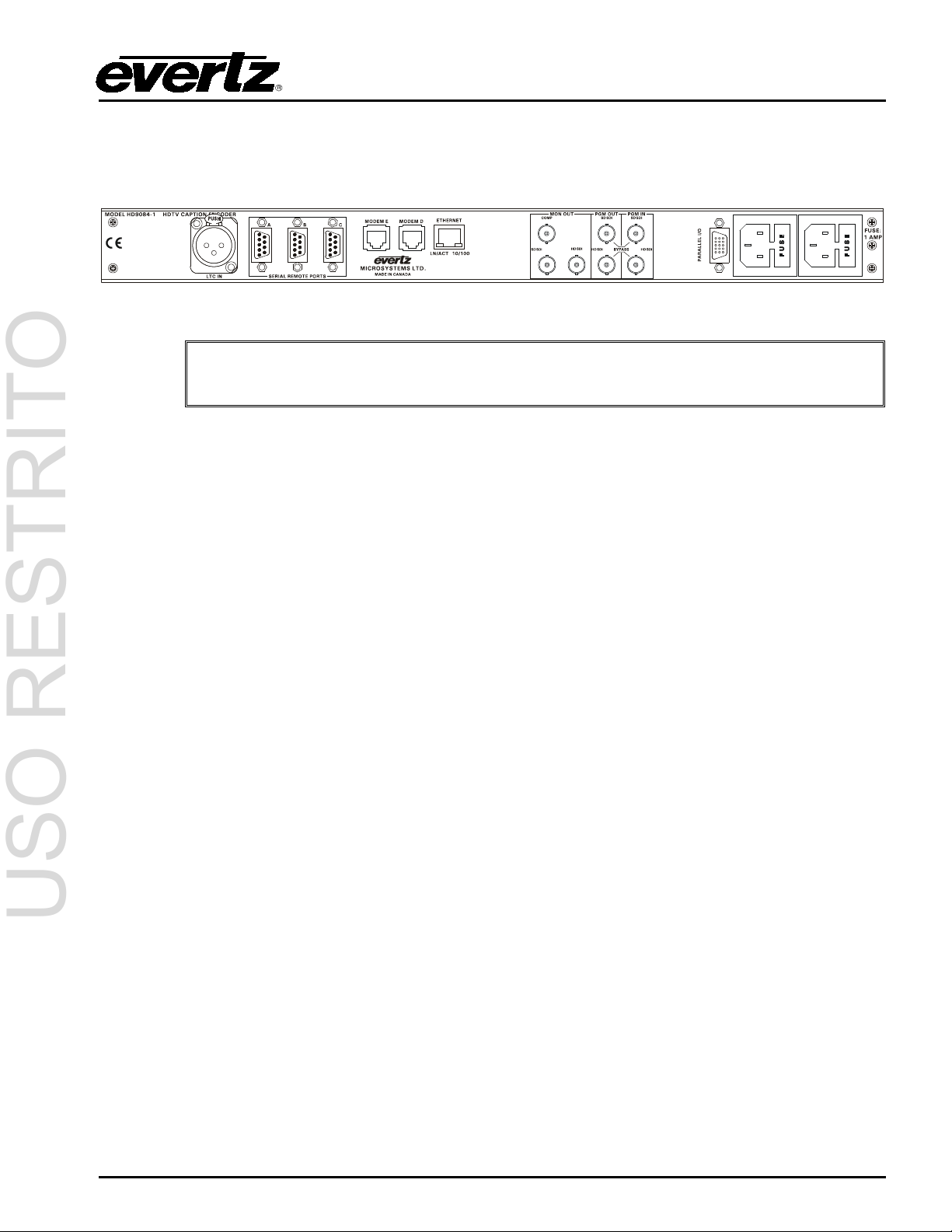
2.1. REAR PANEL
Figure 2-1: Rear Panel of HD9084
Note: The LTC IN connector is currently not supported.
2.1.1. Program Video Inputs (PGM IN)
2.1.1.1. SD SDI
The SD SDI input is a single BNC compatible with SMPTE 259M-C format(s). This input supports
upstream SD video and upstream SD video with caption information. The bypass relay comes
standard with the HD9084 and is enabled using the front panel controls. Please ref er to section 3.1.5
for more information regarding the SD bypass relay.
2.1.1.2. HD SDI
The HD SDI input is a single BNC compatible with SMPTE 292M 1.485 Gb/s 1080i, 720p, 480p
format(s). This input supports upstream HD video and upstream HD video with 334M caption
information. The bypass relay comes standard with the HD9084 and is enabled using the front panel
controls. Please refer to section 3.1.5 for more information regarding the HD bypass relay.
2.1.2. Program Video Outputs (PGM OUT)
2.1.2.1. SD SDI
The SD SDI output is a single BNC compatible with SMPTE 259M-C format(s). The SD SDI outputs
SD SDI video or SD SDI video with CEA 608 captions in line 21. A bypass relay comes standard with
the HD9084 and is enabled using the front panel controls. Please refer to section 3.1.5 for more
information regarding the SD bypass relay.
2.1.2.2. HD SDI
The HD SDI output is a single BNC compatible with SMPTE 292M 1.485 Gb/s 1080i, 720p, 480p
format(s). The HD SDI outputs HD SDI video or HD SDI video with 334M captions in the VANC of the
HD video signal. A bypass relay comes standard with the HD9084 and is enabled using the front panel
controls. Please refer to section 3.1.5 for more information regarding the HD bypass relay.
INSTALLATION Page 2-1

Do not use “gender changers” or “in house fabricated cables” to connect the HD9084
and connect directly from the HD9084 to the ATSC encoder.
USO RESTRITO
HD9084 HDTV Caption Encoder Manual
2.1.3. Monitor Video Output (MON OUT)
2.1.3.1. COMP
1 BNC connector is provided for the output of the composite analog video signal. The COMP Output
provides decoded CEA-708 and CEA-608 open captions burned over the video f or SD-SDI. The f ront
panel menus are used to determine which data channel will be decoded. This output can be connected
to any analog monitor to verify that the program data has been encoded correctly on the program path.
If the bypass relay is activated, this connector will have NO video output. Please see the DECO DE
SETUP menu for further setup instructions.
Note that HD video will NOT be present on the monitor output, however, the
decoded captions will be displayed.
2.1.3.2. HD SDI
1 BNC connector for output of HD SDI digital video signals compatible with the SMPTE 292M 1.485
Gb/s 1080i, 720p, 480p standard(s). This output is ident ical to the PGM HD SDI output except it is not
bypass protected. If the bypass relay is activated, this connector will have NO video output.
2.1.4. Serial Remote Ports
2.1.4.1. Port A
Port A is a 9-pin male 'D' connector for connection to a computer or captioning equipment. Port A
functionality includes updating firmware (see section 5.2) and Control A functions (section 3.8.7). T he
front panel menus are used to set the correct baud rate, word size and parity for use with your
captioning software.
As configured from the factory, the pin-out of this connector is designed for use with a readily available
“null modem” cable to connect to your computer via RS-232 port. It is recommended to keep Port A
free for firmware upgrades.
2.1.4.2. Port B
Port B is a 9-pin male 'D' connector for connection to a computer or captioning equipment. The front
panel menus are used to set the correct baud rate, word size and parity. Port B is used for transfer of
SMPTE 333M / Grand Alliance captions, and Control A protocol.
As configured from the factory, the pin-out of this connector is designed for use with a readily available
“null modem” cable to connect to your computer via RS-232 port.
Connecting the HD9084 to an ATSC encoder may require a null modem cable or straight-through
cable. Please check with the ATSC encoder manufacturer or ATSC manual for the correct cable type.
to the ATSC encoder. Always use a “store bought” Null or Straight through cable
Page 2-2 INSTALLATION

USO RESTRITO
HD9084 HDTV Caption Encoder Manual
2.1.4.3. Port C
Port C is a 9-pin male 'D' connector for connection to a computer or captioning equipment. Port C is
used for Control A protocol. The front panel menus are used to set the correct baud rate, word size
and parity for use with your captioning software.
As configured from the factory, the pin-out of this connector is designed for use with a readily available
“null modem” cable to connect to your computer via RS-232 port.
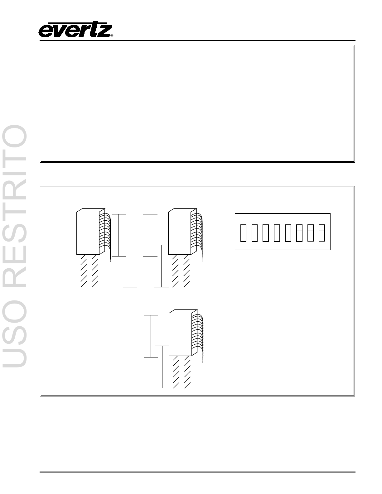
2.1.4.4. Configuring Ports for RS-232
Ports A, B, and C are configured for RS-232 standard from the factory. Setting the HD9084’s serial
ports to RS-232 is done by first removing the lid and locating the ribbon cables for Ports A (J31),
B(J30), and C(J29) on the motherboard. The connectors are located on the right-hand side of the board
with the front panel facing the user. Next, move the three ribbon connectors to the allocated position
marked “232” on the motherboard and set DIP switch 6, 7 or 8 to the OFF position. Dip 6=Port A, Dip
7=Port B, and Dip 8=Port C. The port(s) are now configured for RS-232.
Serial I/O Port ( A, B, C) Computer End
Male (pins) Male (pins)
Description DB-9 DB-25 DB-9 Description
Shield Shield
RS 232 Transmit 3 3 2 RS 232 Receive
Ground 5 7 5 Sig nal Ground
RS 232 Receive 2 2 3 RS 232 Transmit
RS 232 CTS 8 4 7 RS 232 RTS
RS 232 DTR 4 6 6 RS 232 DSR
RS 232 RTS 7 5 8 RS 232 CTS
RS 232 DSR 6 20 4 RS 232 DTR
Figure 2-2: Wiring RS-232 DTE Serial Port to Computer
INSTALLATION Page 2-3

232
422
232
422
232
422
J29
J30
J31
ON
1 2 3 4 5 6 7 8
USO RESTRITO
HD9084 HDTV Caption Encoder Manual
Figure 2-3: RS-232 Configuration
It is not recommended for Port A to be set to RS-422 mode since this port is used
for Firmware upgrades in RS-232 mode.
2.1.4.5. Configuring Ports for RS-422
Ports A, B, or C can each be configured for RS-422. Setting the HD9084’s serial ports to RS-422 is
executed by first removing the lid and locating the ribbon cables for Ports A(J31), B( J30), and C(J29)
on the motherboard. The connectors are located on the right-hand side of the board with the front panel
facing the user. Next, move the ribbon connector(s) to the allocated position marked “422” on the
motherboard and set DIP switch 6, 7, or 8 to the ON position. DIP 6=Port A, DIP 7= Port B, and DIP
8=Port C. The Port(s) are now configured for RS-422 or RS-232.
Page 2-4 INSTALLATION
232
422
232
422
232
422
J29
J30
J31
ON
1 2 3 4 5 6
7 8
USO RESTRITO
HD9084 HDTV Caption Encoder Manual
Serial I/O Port (A, B, C) Computer “Master” End
Male (pins) Female
Description DB-9 DB-9 Description
Shield Shield
Frame Ground 1 1 Frame Ground
Transmit Common 6 6 Receive Common
Transmit - 2 2 Receive Transmit + 7 7 Receive +
Receive + 3 3 Transmit +
Receive - 8 8 Transmit Receive Common 4 4 Transmit Common
Frame Ground 9 9 Frame Ground
not used 5 5 not used
Figure 2-4: Wiring RS-422 Tributary Serial Port to RS-422 Master
INSTALLATION Page 2-5
Figure 2-5: RS-422 Configuration

F ELECTRIC SHOCK, GROUNDING OF
USO RESTRITO
HD9084 HDTV Caption Encoder Manual
2.1.5. Modems
The MODEM D and MODEM E RJ11 jacks are used to connect the inter nal modems of the HD9084 to
a telephone line, allowing computers at other locations running captioning software to communicate
with the HD9084. Use of the MODEM E port requires the HD9084+MDM2 option to be installed in your
unit. If the option is not ordered, the RJ11 jack will not be connected internally. The front panel
engineering menus are used to set the correct baud rate, word size and parity for use with your
captioning software.
IMPORTANT INSTALLATION NOTICE:
For a reliable telephone connection to the modem in the caption encoder, a
2.1.6. Parallel I/O- DB15 Parallel I/O Connector
A DB15 15-pin female connector is used for General Purpose Input (GPI) and General Purpose Output
(GPO) control. Each input/output is optically isolated. Refer to section 2.4 and 2.5 for GPI/O
configurations.
direct telephone line must be used. This line must not pass t hr ough a PBX
or similar key device.
2.1.7. Power Supply
The HD9084 has one or two (redundant supply is optional) universal power supplies that operate on
either 100-115 or 220-240 volts AC at 50 or 60 Hz and automatically senses the input voltage. Power
should be applied by connecting a 3-wire grounding type power supply cord to the power entry modules
on the rear panel. The power cord should be a minimum 18 AWG wire size; type SVT marked VW-1,
maximum 2.5 m in length.
The IEC 320 power entry modules combine a standard power inlet connector, two 5 x 20 mm fuse
holders and an EMI line filter. For instructions on changing the fuses see section 5.3.1.
CAUTION - TO REDUCE THE RISK O
MAINS PLUG GROUND PIN MUST BE MAINTAINED
2.2. MOUNTING
The HD9084 Closed Caption Encoder is equipped with rack mounting angles and fits into a standard 19
inch by 1 3/4 inch (483 mm x 45 mm) rack space. The mounting angles may be removed if rack
mounting is not desired.
2.3. PARALLEL REMOTE CONTROL CONNECTIONS
A DB15 connector provides a method of connecting the remote control GPI signals to control the
caption encoder. The user can configure the GPI/O functionality of the HD9084 via the front panel
control. The pin assignment of the connector is as follows:
Page 2-6 INSTALLATION

Pin #
Name
Description
1
GND
Chassis ground
2
GPO2
General purpose output 2
3
GPO1
General purpose output 1
4
GPO3
General purpose output 3
5
GPIC
General purpose input
6
GPO4
General purpose output 4
7
GPIF
General purpose input (SD Bypass Relay)
8
GPIA
General purpose input
9
GPID
General purpose input
10
GP+3.3V
+3.3V from general purpose interface board
12
GPIE
General purpose input
13
GPIG
General Purpose Input (HD Bypass Relay)
14
GPIB
General purpose input
15
VEXT (in)
External voltage source for GPI's
USO RESTRITO
HD9084 HDTV Caption Encoder Manual
Figure 2-6: GPI/O Pin Identification
Pin 10 and Pin 15 can be jumped in order to provide a VEXT (IN) GPI/O pull-up
2.4. GPI/O SETUP
The following features of the HD9084 can be controlled via parallel port:
• SD-SDI Field 1 Keyer and Field 2 Keyer: See Video Setup (Section 3.4.2)
• HD-SDI VANC Keyer Ctrl: See Video Setup (Section 3.4.3.2)
• Upstream Caption Source Selection: See Video Setup (Section 3.4.4)
• GPI Caption Shift: See Ports Setup (Section 3.6.4)
• Port Enable/Disable: See Ports Setup (Section 3.6.1.4)
• GPO Output Configuration: See Ports Setup (Section 3.6.7)
source voltage with 3.3V.
INSTALLATION Page 2-7
USO RESTRITO
HD9084 HDTV Caption Encoder Manual
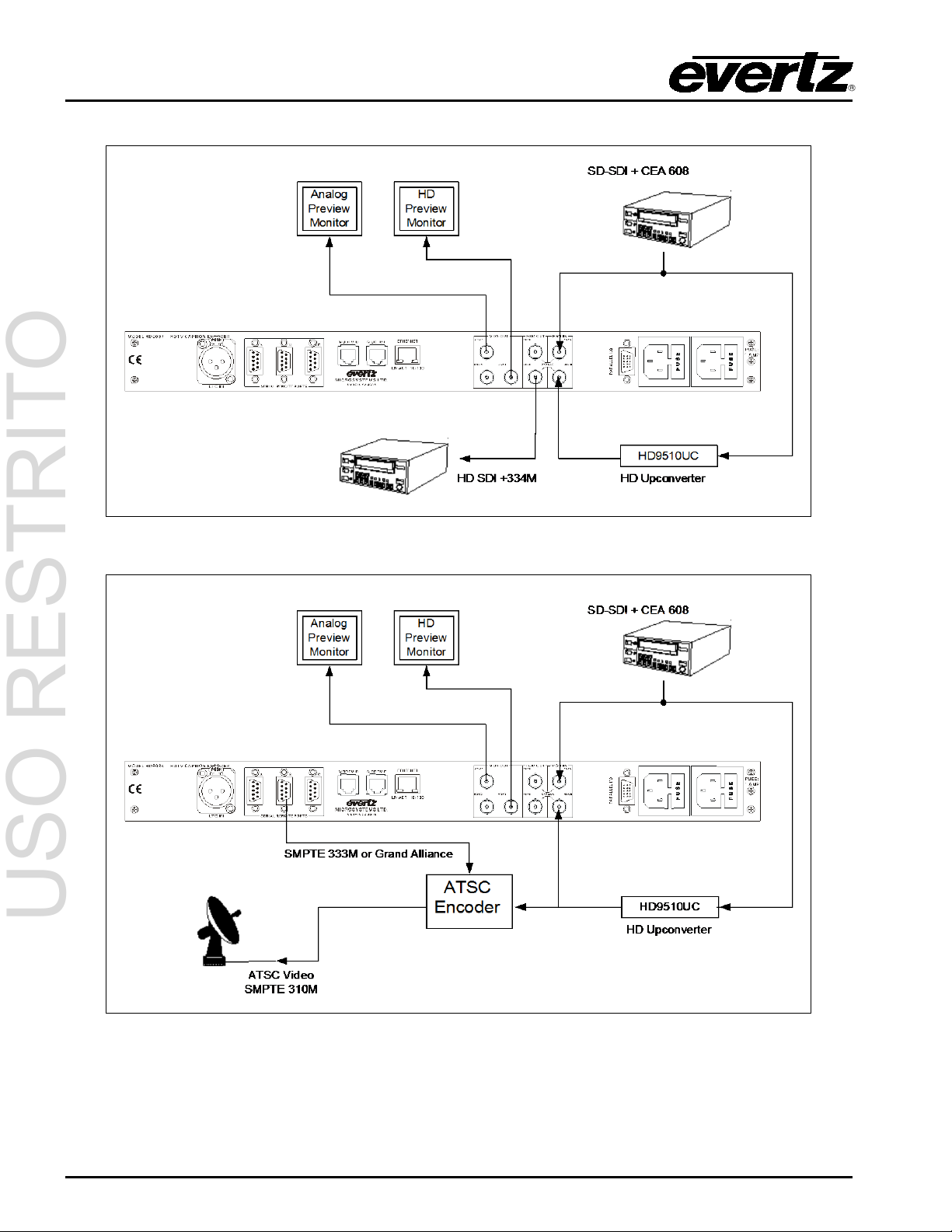
2.5. TYPICAL HD9084 CONFIGURATIONS
Figure 2-7: HD VANC SMPTE-334 Configuration
Figure 2-8: SMPTE-333 or Grand Alliance Configuration
Page 2-8 INSTALLATION
 Loading...