

evertz EQX-IP18-IPG User Manual

EQX–IP18-IPG
EQX Input and IP Gateway Module
User Manual
© Copyright 2016
EVERTZ MICROSYSTEMS LTD.
5292 John Lucas Drive
Burlington, Ontario
Canada L7L 5Z9
Phone: +1 905-335-3700
Sales: sales@evertz.com Fax: +1 905-335-3573
Tech Support: service@evertz.com Fax: +1 905-335-7571
Web Page:
Version 1.0, May 2016
The material contained in this reference guide c onsists of information that is the property of Evertz Microsystems and is intended solely for the use
of purchasers of the EQX-IP18-IPG product. Evertz Microsystems expressly prohibits the use of this guide for any purpose other than the
operation of the contained in this referenc e guide c onsists of information that is the property of Evert z Microsystems and is intended solely for the
use of purchasers of the EQX-IP18-IPG product. Due to on going research and development, features and specifications in this manual are
subject to change without notice.
All rights reserved. No part of this publication may be reproduced without the express written permission of Evertz Microsystems Ltd. Copies of
this manual can be ordered from your Evertz dealer or from Evertz Microsystems.
http://www.evertz.com

This page left intentionally blank

IMPORTANT SAFETY INSTRUCTIONS
WARNING
APPARATUS
TO RAIN OR MOISTURE
WARNING
DO NOT EXPOSE THIS EQUIPMENT TO DRIPPING OR SPLASHING AND ENSURE THAT NO
OBJECTS FILLED WITH LIQUIDS ARE PLACED ON THE EQUIPMENT
WARNING
TO COMPLETELY DISCONNECT THIS EQUIPMENT FROM THE AC MAINS, DISCONNECT THE
POWER SUPPLY CORD PLUG FROM THE AC RECEPTACLE
WARNING
THE MAINS PLUG OF THE POWER SUPPLY CORD SHALL REMAIN READILY OPERABLE
The lightning flash with arrowhead symbol within an equilateral triangle is
intended to alert the user to the presence of uninsulated “Dangerous voltage”
within the product’s enclosure that may b e of suffic ient magn itude to c onstitu te
a risk of electric shock to persons.
The exclamation point within an equilateral triangle is intended to alert the user
to the presence of important operating and maintenance (Servicing) instructions
in the literature accompanying the product.
• Read these instructions
• Keep these instructions.
• Heed all warnings.
• Follow all instructions.
• Do not use this apparatus near water
• Clean only with dry cloth.
• Do not block any ventilation openings. Install in accordance with the manufacturer’s instructions.
• Do not install near any heat sources such as radiators, heat registers, stoves, or other apparatus
(including amplifiers) that produce heat.
• Do not defeat the safety purpose of the polarized or grounding-type plug. A polarized plug has two
blades with one wider than other. A grounding-type plug has two blades and a third grounding prong.
The wide blade or the third prong is provided for your safety. If the provided plug does not fit into your
outlet, consult an electrician for replacement of the obsolete outlet.
• Protect the power cord from being walked on or pinched particularly at plugs, convenience
receptacles and the point where they exit from the apparatus.
• Only use attachments/accessories specified by the manufacturer
• Unplug this apparatus during lightning storms or when unused for long periods of time.
• Refer all servicing to qualified service personnel. Servicing is required when the apparatus has been
damaged in any way, such as power-supply cord or plug is damaged, liquid has been spilled or
objects have fallen into the apparatus, the apparatus has been exposed to rain or moisture, does not
operate normally, or has been dropped.
TO REDUCE THE RISK OF FIRE OR ELECT RIC – SHO CK, DO NOT EXPOSE THIS

EN60065
Safety
EN55103-1: 1996
Emission
EN55103-2: 1996
Immunity
INFORMATION TO USERS IN EUROPE
NOTE
CISPR 22 CLASS A DIGITAL DEVICE OR PERIPHERAL
This equipment has been tested and found to comply with the limits for a Class A digital device, pursuant
to the European Union EMC directive. These limits are designed to provide reasonable protection
against harmful interference when the equipment is operated in a commercial environment. This
equipment generates, uses, and can radiate radio frequency energy and, if not installed and used in
accordance with the instruction manual, may cause harmful interference to radio communications.
Operation of this equipment in a residential area is likely to cause harmful interference in which case the
user will be required to correct the interference at his own expense.
Waste electrical products should not be
disposed of with household waste.
Contact your Local Authority for recycling
EN504192 2005
advice
INFORMATION TO USERS IN THE U.S.A.
NOTE
FCC CLASS A DIGITAL DEVICE OR PERIPHERAL
This equipment has been tested and found to comply with the limits for a Class A digital device, pursuant
to Part 15 of the FCC Rules. These limits are designed to provide reasonable protection against harmful
interference when the equipment is operated in a commercial environment. This equipment generates,
uses, and can radiate radio frequency energy and, if not installed and used in accordance with the
instruction manual, may cause harmful interference to radio communications. Operation of this
equipment in a residential area is likely to cause harmful interference in which case the user will be
required to correct the interference at his own expense.
WARNING
Changes or Modifications not expressly approved by Evertz Microsystems Ltd. could void the user’s
authority to operate the equipment.
Use of unshielded plugs or cables may cause radiation interference. Properly shielded interface cables
with the shield connected to the chassis ground of the device must be used.

EQX–IP18-IPG
EQX Input and IP Gateway Module
TABLE OF CONTENTS
1. OVERVIEW ................................................................................................................................... 1
VIDEO/IP CONNECTIONS ..................................................................................................................... 2
AUDIO CONNECTIONS ......................................................................................................................... 2
2. SPECIFICATIONS ......................................................................................................................... 3
2.1. SERIAL DIGITAL VIDEO INUPUTS ..................................................................................... 3
2.2. ELECTRICAL ....................................................................................................................... 3
2.3. FRAMES ............................................................................................................................... 3
3. FRAME TYPES ............................................................................................................................. 5
4. INSTALLATION ............................................................................................................................. 7
4.1. INSTALLATION OF REAR PLATE OR MODULE INTO TOP HALF OF A EQX26 FRAME . 7
4.2. INSTALLATION OF REAR PLATE OR MODULE INTO BOTTO M HALF OF AN EQX26
FRAME ................................................................................................................................. 9
5. SETTING GENLOCK REFERENCE ............................................................................................ 11
5.1. NTSC REFERENCE ........................................................................................................... 11
5.2. PAL REFERENCE .............................................................................................................. 12
6. CHECKING INPUT STATUS WITH LEDS ON THE MODULE .................................................... 13
7. WEB INTERFACE CONFIGURATION ........................................................................................ 15
7.1. LOGIN ................................................................................................................................. 15
7.2. SYSTEM TAB ..................................................................................................................... 16
7.2.1. Data Port Configuration ........................................................................................... 16
7.2.2. Data Port Monitor ..................................................................................................... 16
7.2.3. Rear Panel ............................................................................................................... 17
7.2.4. SFP Monitor ............................................................................................................. 18
7.2.5. Genlock Configuration ............................................................................................. 19
7.2.6. Genlock Monitoring .................................................................................................. 19
7.2.7. Temperature ............................................................................................................ 19
7.2.8. TRAP Destination IP ................................................................................................ 20
7.2.9. Standard Control ...................................................................................................... 20
7.2.10. Configuration Management ...................................................................................... 20
7.2.11. RPC Control ............................................................................................................ 21
7.2.12. Card Control ............................................................................................................ 22
7.3. LICENSE ............................................................................................................................ 23
7.3.1. License Control ........................................................................................................ 23
7.3.2. Product Feature ....................................................................................................... 23
TABLE OF CONTENTS Revision 1.0 Page - i

EQX–IP18-IPG
EQX Input and IP Gateway Module
7.4. INPUT ROUTE CONTROL ................................................................................................. 24
7.4.1. Route (Grid/ Management) ...................................................................................... 24
7.5. OUTPUT ROUTE CONTROL ............................................................................................. 25
7.5.1. Output Route (Grid/Management) ........................................................................... 25
7.6. DIN SDI INPUTS ................................................................................................................ 26
7.6.1. SDI Input Control .................................................................................................... 26
7.6.2. SDI Input Monitoring ............................................................................................... 27
7.6.3. SDI Port Control ...................................................................................................... 27
7.7. IP OUTPUT ........................................................................................................................ 28
7.7.1. IP Output Control .................................................................................................... 28
7.7.2. IP Output Advanced Control ................................................................................... 29
7.7.3. IP Output Monitoring ............................................................................................... 30
7.8. IP INPUT CONTROL .......................................................................................................... 31
7.8.1. Global Control ......................................................................................................... 31
7.8.2. IP Input Control ....................................................................................................... 32
7.8.3. Preset IP Input Control ............................................................................................ 32
7.9. IP INPUT MONITORING .................................................................................................... 33
7.9.1. IP Input Monitoring .................................................................................................. 33
7.9.2. IP Input Monitoring .................................................................................................. 33
7.10. SDI OUTPUT ...................................................................................................................... 34
7.11.1. Router Source ......................................................................................................... 34
7.11.2. Router Source ......................................................................................................... 35
7.11.3. SDI Outpu t Gl o bal ................................................................................................... 35
7.11.4. SDI Output Control .................................................................................................. 35
7.11.5. SDI Output Monitoring ............................................................................................. 36
7.11.6. SDI Port Control ...................................................................................................... 36
7.12. VIDEO NOTIFY .................................................................................................................. 37
7.12.1. Video Monitoring Control ......................................................................................... 37
7.12.2. Video Input Notify .................................................................................................... 37
7.12.3. Video Output Notify ................................................................................................. 37
7.13. AUDIO NOTIFY .................................................................................................................. 39
7.13.1. Audio Monitoring Control ......................................................................................... 39
7.13.2. Audio Input Notify .................................................................................................... 39
7.13.3. Audio Output Notify ................................................................................................. 39
7.14. IP NOTIFY .......................................................................................................................... 40
7.14.1. Ethernet Fault ......................................................................................................... 40
7.14.2. Encapsulator Fault .................................................................................................. 41
7.14.3. Decapsulator Fault .................................................................................................. 41
7.15. NOTIFY .............................................................................................................................. 42
7.15.1. SDI Input Notify ....................................................................................................... 42
7.15.2. Fan Notify ............................................................................................................... 42
7.16. TASKBAR FUNCTIONS .................................................................................................... 44
7.16.1. Firmware Upgrade .................................................................................................. 44
Page - ii Revision 1.0 TABLE OF CONTENTS

EQX–IP18-IPG
EQX Input and IP Gateway Module
Figures
Figure 1-1: EQX-IP18-IPG Block Diagram ....................................................................................................... 2
Figure 3-1: Standard 26RU, 16RU, and 10RU Frames ................................................................................... 5
Figure 4-1: Rear Plate Orientation when Installing to the Top half of the Frame ............................................. 7
Figure 4-2: Illustration EQX-IP18-IPG Installed in the Top Slot ....................................................................... 8
Figure 4-3: Rear Plate Orientation When installing to the Bottom of the Frame .............................................. 9
Figure 4-4: Illustration EQX -IP18-IPG Installed in the Bottom Slot ................................................................ 10
Figure 5-1: Location of Dip Switch on the EQX–IP18-IPG Module ................................................................ 11
Figure 5-2: Illustration of Dip Switch .............................................................................................................. 11
Figure 6-1: LED Indicators when installed in the Top half of the Frame ........................................................ 13
Figure 6-2: LED Indicators when Installed in the Bottom half of the Frame ................................................... 14
Figure 7-1: Web Interface - Login Sc reen ...................................................................................................... 15
Figure 7-2: Web Interface - System Tab – Data Port Configuration .............................................................. 16
Figure 7-3: Web Interface - System Tab – Data Port Monitor ........................................................................ 17
Figure 7-4: Rear Panel ................................................................................................................................... 18
Figure 7-5: SFP Monitor ................................................................................................................................. 18
Figure 7-6: Genlock Configuration ................................................................................................................. 19
Figure 7-7: Genlock Monitoring ...................................................................................................................... 19
Figure 7-8: Temperature ................................................................................................................................. 19
Figure 7-9: Trap Destination ........................................................................................................................... 20
Figure 7-10: Standard Control ........................................................................................................................ 20
Figure 7-11: Configuration Mana gement ........................................................................................................ 22
Figure 7-12: License Tab ................................................................................................................................ 23
Figure 7-13: Web Interface - Input Route Control Tab 1 ................................................................................ 24
Figure 7-14: Web Interface - Input Route Control Tab 2 ................................................................................ 25
Figure 7-15: Web Interface - Output Route Control Tab ................................................................................ 25
Figure 7-16: SDI Input Tab ............................................................................................................................. 26
Figure 7-17: Web Interface - IP Output Tab ................................................................................................... 28
Figure 7-18: IP Output Advanced Control ...................................................................................................... 29
Figure 7-19: IP Output Monitoring .................................................................................................................. 30
Figure 7-20: IP Input Control Tab ................................................................................................................... 31
Figure 7-21: IP Input Monitoring Tab .............................................................................................................. 33
Figure 7-22: SDI Output Tab .......................................................................................................................... 34
Figure 7-23: SDI Output Monitoring ............................................................................................................... 36
Figure 7-24: Video Notify Tab......................................................................................................................... 37
Figure 7-25: Video Output Notif y .................................................................................................................... 38
Figure 7-26: Web Interface - Audio Notify Tab ............................................................................................... 39
Figure 7-27: IP Notify Tab .............................................................................................................................. 40
Figure 7-28: Notify Tab ................................................................................................................................... 42
Figure 7-29: Webeasy Taskbar ...................................................................................................................... 44
Figure 7-30: Firmware Upgrade ..................................................................................................................... 44
Tables
Table 2-1: Supported Video Standards ............................................................................................................ 3
Table 5-1: Card Edge Dip Switch Settings for NTSC Reference ................................................................... 11
Table 5-2: Card Edge Dip Switch Settings for PAL Reference ...................................................................... 12
TABLE OF CONTENTS Revision 1.0 Page - iii

EQX–IP18-IPG
EQX Input and IP Gateway Module
This page left intentionally blank
Page - iv Revision 1.0 TABLE OF CONTEN TS

EQX–IP18-IPG
EQX Input and IP Gateway Module
REVISION HISTORY
REVISION DESCRIPTION DATE
1.0 First Release May 2016
Information contained in this reference guide is beli eved to be accurate and reliable. However, Evertz assumes no responsibili ty for the use
thereof nor for the rights of third parties, which may be affected in any way by the use thereof. Any representations in this document
concerning performance of Evertz products are for inform ational use only and are not warranties of future performance, either express ed or
implied. The only warranty offered by Evertz in relation to this product is the E vertz standard limited warranty, stated in the s ales contract or
order confirmation form.
Although every attempt has been made to accurately describe the features, installation and operation of this product in this reference guide,
no warranty is granted nor liability assumed in relation to any errors or omissions unless specifically undertaken in the Evertz s al es c ontract or
order confirmation. Information contained in this reference guide is periodically updated and changes will be incorporated into subsequent
editions. If you encounter an error, please notify Evertz Customer Service department. Evertz reserves the right, without notic e or liability, to
make changes in equipment design or specifications.
Revision 1.0 Page - v

EQX–IP18-IPG
EQX Input and IP Gateway Module
This page left intentionally blank
Page - vi Revision 1.0

EQX–IP18-IPG
EQX Input and IP Gateway Module
1. OVERVIEW
EQX-IP18-IPG is an 18-channel hybrid EQX input module that allows existing or new EQX routers the
ability to bridge to the IP world. This IP Gateway module is fully featured with the ability for
encapsulation and de-encapsulation of video signals over IP. There are 18 inputs on the EQX that c an
be selected for either baseband inputs or 10GE IP sources, eac h of the 18 inputs have a framesync
designed to re-time the input video signal to the EQX frame reference signal. The EQX-IP18-IPG
modules manage SDI video or 10GE IP source with or without embedded audio signal from 3Mb/s
through to 3Gb/s. It also de-embeds audio from all 18 inputs and multiplexes them onto 2 TDM
streams, one main and one redundant. Either TDM stream can be used as the primary since they are
both indentical.
The EQX input and IP gateway module provides a future proofing answer to the SDI bas ed router and
infrastructure, allowing for a smooth integration under MAGNUM Unified Control system for Evertz
Software Defined Video Network (SDVN) solu tion.
Like all other EQX input cards, the EQX-IP18-IPG is cooled by the EQX-FAN-BIN, fully hotswappable
and accessed from the front of the EQX frame. The EQX router can be loaded with a maximum of 32
EQX-IP18-IPG modules providing square and non-square matrix configurations from as small as 18
inputs through to 576 inputs.
The EQX-IP18-IPG hybrid input card provides a gateway to link into IP infrastructures as well as allow a
more efficient way to tieline routers together. IP based video packetized and transported over fiber will
provide greater density and longer distances than coax based solutions would yield, yet still maintaining
the low latency and proper SDI SMPTE switching capabilities in the EQX.
For added system flexibility the EQX-IPG-DIN-RP can be used with a standard 18 input 3G and HD
Green modules utilizing our IP ready adapter module.
Features & Benefits
• 18 SD/HD/3G SDI inputs
• 18 uncompressed IP inputs (de-encapsulators)
• 18 uncompressed IP outputs (encapsulators)
• Six 10 GbE interfaces
• Fully compatible with all EQX frame models
• Full Audio demux (AVIP) for all sources ( SDI or IP ,18 total) over TDM so that it can be
routed/processed separately
• Full framesync option for all 18 sources
• Four additional frames of delay can be added
• Support SMPTE ST 259, SMPTE ST 292-1, SMPTE ST 425-1 Level A
• Input expansion in increments of 18, from 18 t hr ough to 576
• Access to all modules from front of the EQX
• All modules are hot-swappable
• Fan cooled by EQX-FAN-BIN
Revision 1.0 Page - 1
EQX–IP18-IPG
EQX Input and IP Gateway Module
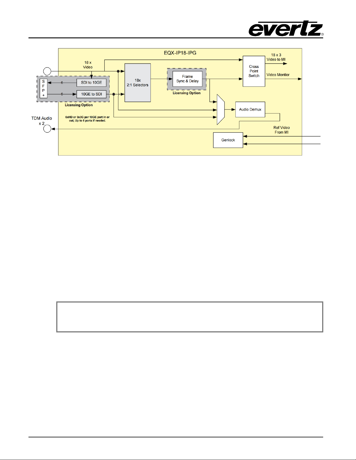
Figure 1-1: EQX-IP18-IPG Block Diagram
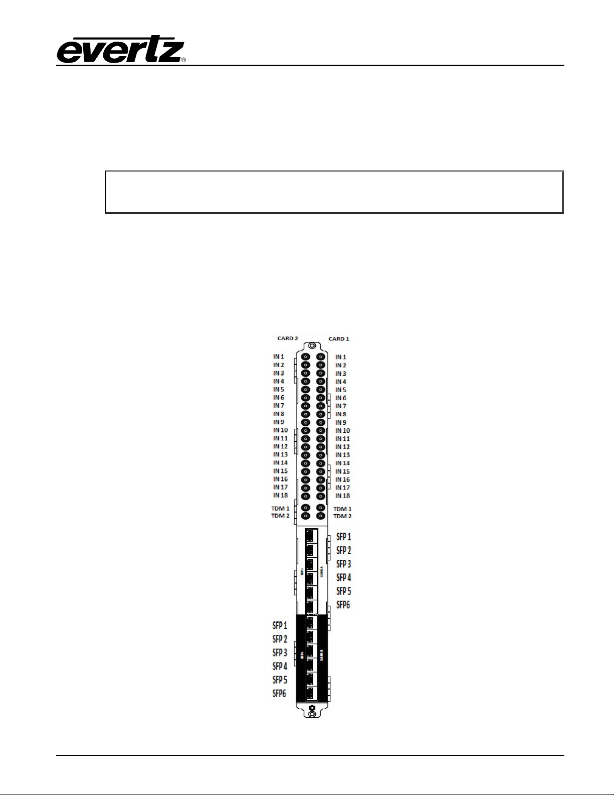
VIDEO/IP CONNECTIONS
• 18 SDI Mini DIN Inputs: The 18 Mini DIN connectors are compatible with SMPTE ST 259,
SMPTE ST 292-1 and SMPTE ST 425-1 Level A input signals. T he module can aut omatically
detect the input video standard.
• 6 SFP+ Connectors: The six SFP+ data ports are bi-directional and can be used for both
encapsulation and de-encapsulation for the SDI streams. Supports SMPTE ST 259, SMPTE
ST 292-1 and SMPTE ST 425-1 Level A input and output signals.
AUDIO CONNECTIONS
• 2 TDM Outputs: Two Mini DIN connectors for TDM audio (compatible with Eve rtz TDM v2 only)
Note: EQX-IP18-IPG only supports the RPC based system. All input and output
modules including the frame controller must have the RPC based firmware. There
is no FLink support for the EQX-IP18-IPG.
Page - 2 Revision 1.0

525i/59.94
625i/50
1080p 59.94
1080p 50
1080i 59.94
1080i 50
720p59.94
720p50
1080i60
720p60
1080p 60
2. SPECIFICATIONS
2.1. SERIAL DIGITAL VIDEO INUPUTS
Standards : The following video standards are auto detectable
Table 2-1: Supported Video Standards
Number of SDI inputs: 18 x Mini DIN
Number of SFP Ports: 6 x SFP+
Impedance : 75 Ω terminating
Input Equalization:
SD Standards : Automatic to 190m @ 270Mb/s with Belden 1694 or
equivalent cable
HD Standards : Automatic to 135m @ 1.5Gb/s with Belden 1694 or
equivalent cable
3G Standards : Automatic to 90m @ 3Gb/s with Belden 1694 or equivalent
cable
DC Offset: 0 ±0.5 V
Output Jitter:
SD Standards : < 0.2 UI
HD Standards : < 0.2 UI
3G Standards : < 0.3 UI
EQX–IP18-IPG
EQX Input and IP Gateway Module
2.2. ELECTRICAL
2.3. FRAMES
Revision 1.0 Page - 3
Voltage: +48VDC
Power Consumption: 55W
Frame and Slot Occupancy: EQX10 Frame with 1 slot occupancy
EQX16 Frame with 1 slot occupancy
EQX26 Frame with 1 slot occupancy

EQX–IP18-IPG
EQX Input and IP Gateway Module
This page left intentionally blank
Page - 4 Revision 1.0
EQX–IP18-IPG
EQX Input and IP Gateway Module
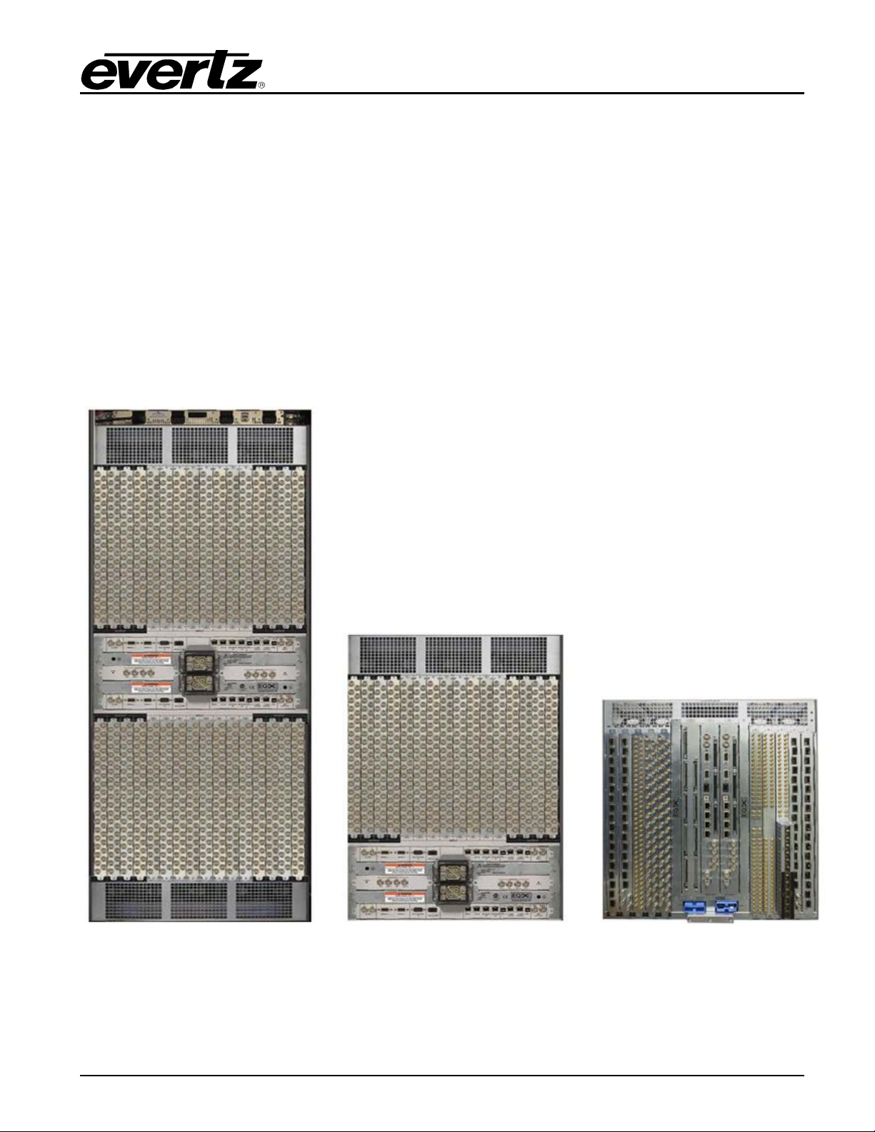
3. FRAME TYPES
A typical EQX platform has the ability to route up to 576x576 signals in a standard 26RU frame, up to
288x288 in a standard 16RU frame and up to 180X180 in a 10 RU frame. EQX platform can be
expanded beyond its standard routing capability by adding X-Link expansions to the frame. The most
common frame types are as follow:
1. Standard 26RU,16RU and 10RU frames
2. 26RU frames with Xlink expansion outputs
3. 16RU frames with Xlink expansion outputs
4. 10RU frames with Xlink expansion outputs
For more information on EQX frames see the EQX Series manual.
Figure 3-1: Standard 26RU, 16RU, and 10RU Frames
Revision 1.0 Page - 5

EQX–IP18-IPG
EQX Input and IP Gateway Module
This page left intentionally blank
Page - 6 Revision 1.0
EQX–IP18-IPG
EQX Input and IP Gateway Module
4. INSTALLATION
Before handling the card it is important to minimize the potential effects of static electricity. It is
therefore recommended that an ESD strap be worn.
Locate a vacant slot on the router chassis. Each rear plate can house up to two modules.
Note: The orientation of the rear plate and EQX–IP18-IPG module are different
when installing on the top verses the bottom of the EQX26 frame
4.1. INSTALLATION OF REAR PLATE OR MODULE INTO TOP HALF OF A EQX26 FRAME
Most of the time cards come preinstalled in the frame if both frame and the cards are ordered together.
In the case of installing spare cards and rear plates into the frame, the following steps need to be taken
into consideration.
Step 1 : Install the EQX-IP18-IPG re ar pla t e to the top half of the EQX frame with screws provided and
make sure the orientation of the rear plate is the same as shown in Figure 3-1.
Figure 4-1: Rear Plate Orientation when Installing to the Top half of the Frame
Revision 1.0 Page - 7
 Loading...