

evertz EMX3-FR, EMX6-FR User Manual

High Density Modular Video Router
USER MANUAL
© Copyright 2011 - 2014
EVERTZ MICROSYSTEMS LTD.
5288 John Lucas Drive,
Burlington, Ontario,
Canada L7L 5Z9
Phone: 905-335-3700
Sales: sales@evertz.com Fax: 905-335-3573
Tech Support: service@evertz.com Fax: 905-335-7571
Web Page:
Version 1.4, January 2014
The material contained in this manual consists of information that is the property of Evertz Microsystems and is intended solely for
the use of purchasers of the EMR. Evertz Microsystems expressly prohibits the use of this manual for any purpose other than the
operation of the EMR. Due to on going research and development, features and specifications in this manual are subject to
change without notice.
All rights reserved. No part of this publication may be reproduced without the express written permission of Evertz Microsystems
Ltd. Copies of this manual can be ordered from your Evertz dealer or from Evertz Microsystems.
http://www.evertz.com

The lightning flash with arrowhead symbol within an equilateral triangle is
a risk of electric shoc k to p ersons.
WARNING:
EXPOSE THIS
APPARATUS TO RAIN OR MOISTURE
WARNING:
EXPOSE THIS EQUIPMENT TO DRIPPING OR SPLASHING AND ENSURE THAT NO
OBJECTS FILLED WITH LIQUIDS, SUCH AS VASES, ARE PLACED ON THE EQUIPMENT
WARNING:
TO COMPLETELY DISCONNECT THIS EQUIPMENT FROM THE AC MAINS, DISCONNECT
THE POWER SUPPLY CO R D PL U G FR O M TH E AC R ECEPTACLE
WARNING:
THE MAINS PLUG OF THE POWER SUPPLY CORD SHALL REMAIN READILY OPERABLE
IMPORTANT SAFETY INSTRUCTIONS
in tend ed to aler t t he us er t o the p res enc e of u n-in sul ated , dan ger ous vol tag e
within the product’s enclosure that may be of sufficient magnitude to c ons t i t u t e
The exclamation point within an equilateral triangle is intended to alert the user
to the presence of important operating and maintenance (i.e.: servicing)
instructions in the literature accompanying the product.
• Read these instructions.
• Keep these instructions.
• Heed all warnings.
• Follow all instructions.
• Don ’t us e th is apparat us n ear water .
• Clean only with a dry cloth.
• Don ’t block an y v entilati on openings.
• Install in ac cordance with the manufac tu rer’s in struc tions.
• Don’t install near any heat sources such as radiators, heat registers, stoves, or other
apparatuses (including amplifiers) that produce heat.
• Don ’t def eat t he s afet y p ur pos e of t he p ola ri zed or g r ound in g-typ e plug. A polarized plug has
two blades with one wider than other. A grounding-type plug has two blades and a third
grounding prong. The wide blade or third prong is provided for your safety. If the plug provided
do es not f it i nto your outlet , con sult an elect rician to r epl ace th e obsolete out l et .
• Protect the power cord from being walked on or pinch ed, particularly at plugs, convenience
receptacles , an d t he poi nt wh ere th ey exit fr om the apparat us.
• On ly use attachments/accessories s pecified by th e manufac ture r
• Unplug this apparatus during light ni ng storms, or when unused for long periods of time.
• Refer all servicing to qualified service personnel. S ervici ng is required when the apparatus has
been d amaged in any w ay, such as damag e to the power-supply cord or plug, contact with
liquid (or any obj ect sm al l en ou gh to en te r t he app ar at us ), exp osu r e t o r ai n or m oi st ur e, dr op
damage, or upon ex periencin g any abnormal operati on.
TO REDUCE THE RISK OF FIRE OR ELECTRIC SHOCK, DO NOT
DO NOT

WARNING
Never look directly int o an optical fiber. Irreversib le eye dam age can occur in a
matter of milliseconds.
INFORMATION T O USERS IN EUROPE
For Commercial Use
EN60065
Safety
EN504192 2005
for re cy cl in g adv i ce
EN55103-1: 1996
Emission
EN55103-2: 1996
Immunity
NOTE
This equipment with the CE marking complies with both the EMC Directive (2004/108/EC) and the Low Voltage
Directive (2006/95/EC) issued by the Commission of the European Community.
Comp liance with t hese directives impli es c onformity t o th e followi ng European standards:
• EN60065 Product Safety
• EN55103-1 Elect romag net ic Int erferen ce Class A ( E mis sion)
• EN55103-2 Electromagnetic Susceptibility (Immunity)
This equipm ent has been t ested and foun d to comply with the lim its for a Class A digital device, pursu ant to t he
European Union EMC directive. These limits are designed to provide reasonable protection against harmful
int erference when th e equipmen t is op erated in a commerc ial environ ment. This equ ipment g enerates, uses, and
can radiate radio frequency energy and, if not installed and used in accordance with the instruction manual, may
caus e harmfu l interfe rence to radio c ommun ication s. Operat ion of t his equ ipmen t in a resi dential area is likel y to
cause harmful i nterference in which case the user will be req uired to corr ect t he in terference at his own expense.
Waste electrical products should not
be disposed of with household
waste. Con ta ct your L oca l A ut hority
INFORMATION T O USERS IN THE U.S.A.
NOTE
FCC CLASS A DIGIT AL DEVICE OR PERIPHERAL
This eq u ipm en t has b een t est ed and foun d to c omp ly with th e l im it s for a Cl ass A d ig it al d evice, p u rsu an t to P art 15
of the FCC Rules. These lim its are designed to provide reasonable protection against harmful interference when the
equipment is operated in a commercial environment. This equipment generates, uses, and can radiate radio
frequency energy and, if not installed and used in accordance with the instruction manual, may cause harmful
int erference t o radio c ommu nicat ions. Op eration of this eq uipmen t in a r esidential area is l ikel y to cau se harmfu l
interference in which case the user will be required to c or rect the interferenc e at his own expense.
WARNING
Changes or modifications not expressly approved by Evertz Microsystems Ltd. could void the user’s authority to
operate the equipment. Use of unshielded plugs or cables may cause radiation interference. Properly shielded
interface cables with t he shield connected to the chassis ground of the device must be used
Evertz Microsystems Ltd
Tested to comply
with FCC
Standards
This device complies with part 15 of the FCC Rules. Operation is
subject to the following two conditions:
This device m ay cause harmful int er ference, and this device must
accept any interference rece ived, including interference that may
cause und esired operati on.
.

EMR Video User's Guide
High Density Modular Video Router
REVISION HISTORY
REVISION DESCRIPTION DATE
1.0 First Release Feb 2011
1.1 Updates throughout manual Nov 2011
1.2 Up dates made to “Ethernet Inter face” section Dec 2011
1.3 Updates throughout manua l Nov 2012
1.3.1 Up dated Elec trical specific ation May 2013
1.4 Added Section 6.4 – EMR Fram e Configuration with 4.11 RPC Firmware Jan 2014
and Section 7 – VistaLINK
Information contained in this manual is believed to be accurate and reliable. Howe ver, Evertz assumes no responsibility f or the use thereof, nor for the rights of third
parties, which may be affected in any way by the use thereof. Any representations in this document concerning performance of Evertz products are for informational
use only and are not warrant ies of future performance, either expressed or implied. The only warranty offered by Evertz in relation to this product is the Evertz standard
limit ed warranty, stated in the sales contract or order confir ma tion form.
Althoug h every attempt has been made to accurately describe the features, installation and operation of this product in this manual, no warranty is granted nor liability
assumed in relation to any errors or omissions unless specifically undertake n in the Ever tz sales contract or order confirmation. Information contained in this manual is
periodically updated and changes will be incorporated into subsequent edit ions. If you encounter an error, please notif y Evertz Customer Service department. Evertz
reserves the right, without not ice or liabil it y, to make changes in equipment design or specifications.
Remote M oni toring/Con tr ol
®
Revision 1.4

EMR Video User's Guide
High Density Modular Video R outer
This page left intentionally blank
Revision 1.4

EMR Video User's Guide
High Density Modular Video Router
TABLE OF CONTENTS
1. OVERVIEW .............................................................................................................................. 1
1.1. FEATURES & BEN EF ITS ................................................................................................. 2
2. COMPONENT OVERVIEW ....................................................................................................... 3
2.1. EMR FRAME.................................................................................................................... 3
2.2. EMR I/O MODULES ......................................................................................................... 4
2.2.1. EMR Video Input Modul e ....................................................................................... 4
2.2.1.1. Front Card Edge Controls and LEDs......................................................... 6
2.2.2. EMR Video Output Module ..................................................................................... 7
2.2.2.1. Front Card Edge Controls and LEDs......................................................... 9
2.2.3. EMR Video Crosspoint Module............................................................................. 10
2.2.3.1. Front Card Edge Controls and LEDs....................................................... 13
2.3. EMX-FC FRAME CONTROLLER MODULE .................................................................... 14
2.4. SC-2000 SYSTEM CONTROLLER ................................................................................. 14
2.4.1. SC-2000 I nterf aces .............................................................................................. 15
2.4.2. Ser ial C onnect ion s............................................................................................... 16
2.4.3. SC-2000 Powe r Supply ........................................................................................ 16
2.5. INST ALLING AND REMOVING THE MODULES ............................................................ 18
2.5.1. Installing the Modul e Rear Plat e ........................................................................... 18
2.5.2. Opening and Closing the Front Panel ................................................................... 18
2.5.3. Installing a Module ............................................................................................... 18
2.5.4. Removin g a M odule ............................................................................................. 19
2.6. MOUNTING .................................................................................................................... 19
2.7. COOLING ...................................................................................................................... 19
2.7.1. Fan Exhaust ........................................................................................................ 19
2.8. SERVICING INSTRUCT IONS ......................................................................................... 20
2.8.1. Changing the Fuses ............................................................................................. 20
2.8.2. Replacing the Power Supply ................................................................................ 20
2.9. POWER ......................................................................................................................... 22
2.9.1. Connecting the Power.......................................................................................... 22
2.9.2. Turning the Power On and Off .............................................................................. 23
2.9.3. Power Su pply S tatu s I ndicator s ............................................................................ 23
2.10. FRAME STATUS F AUL T CONDITIONS ......................................................................... 24
2.11. CARE AND HANDLING OF OPTICAL FIBER ................................................................. 24
2.11.1. Safety ................................................................................................................. 24
2.11.2. Assembly ............................................................................................................ 24
TABLE OF CONTENTS Revision 1.4 Page i

EMR Video User's Guide
High Density Modular Video Router
2.11.3. Labeling .............................................................................................................. 24
2.11.4. Handling and Connecting Fibers .......................................................................... 25
3. SPECIFICATIONS .................................................................................................................. 27
3.1. EMR SPECIFICATIONS ................................................................................................. 27
3.1.1. Configuration ...................................................................................................... 27
3.1.2. Video Inputs ........................................................................................................ 27
3.1.3. Video Outputs ..................................................................................................... 27
3.1.4. Sw itching Referen ce ............................................................................................ 27
3.1.5. Control ................................................................................................................ 27
3.1.6. Electrical ............................................................................................................. 28
3.1.7. Physical .............................................................................................................. 28
3.1.8. Compliance ......................................................................................................... 28
3.2. EMX-FC SPECIFICATIONS ........................................................................................... 29
3.2.1. Ethernet .............................................................................................................. 29
3.2.2. Ser ial C ommuni cati ons ........................................................................................ 29
3.2.3. Electrical ............................................................................................................. 29
3.3. SC-2000 SPECIFICA TIONS ........................................................................................... 29
3.3.1. Referen ce Timing ................................................................................................ 29
3.3.2. Ethernet .............................................................................................................. 29
3.3.3. Q-Link ................................................................................................................. 29
3.3.4. Ser ial C ommuni cati ons ........................................................................................ 29
3.3.5. Electrical ............................................................................................................. 30
3.3.6. Physical .............................................................................................................. 30
4. SYSTEM OVERVIEW ............................................................................................................. 31
4.1. SYSTEM CONNECTIONS .............................................................................................. 31
4.1.1. Referencing ........................................................................................................ 35
4.1.2. Inter-frame C able Length Limitations .................................................................... 35
5. EMR AND SC-2000 NETWORK CONFIGURATION ................................................................ 37
5.1. IP CONNECTION SETT INGS ......................................................................................... 38
6. CONFIGURING THE SYSTEM USING WINSETUP ................................................................. 41
6.1. CONFIGURATION OF 288X288 AND 288X288 WITH REDUNDANCY ........................... 41
6.2. CONFIGURATION OF 288X576 ROUTER ...................................................................... 46
6.3. EMR FRAME CONFIGURATION .................................................................................... 48
6.4. EMR FRAME CONFIGURATION WITH 4.11 RPC FIRMWARE ...................................... 52
6.5. COMMUNICATION PORT SETUP.................................................................................. 55
6.5.1. Control P anel Eth ernet In ter fac e .......................................................................... 55
6.5.2. Control P anel Q-Link Int erface ............................................................................. 56
6.5.3. Ser ial I nt erfac e .................................................................................................... 57
Page ii Revision 1.4 TABLE OF CONTENTS

EMR Video User's Guide
High Density Modular Video Router
6.5.4. Ethernet Interface ................................................................................................ 58
7. VISTALINK® RE MOTE MONITORING/CONTROL .................................................................. 59
7.1. WHAT IS VIST ALINK ? ................................................................................................... 59
7.2. VISTALINK® RE MOTE MONITORING/CONTROL FOR SC-2000-EMR .......................... 60
7.2.1. General Mon itoring and Contr ol Parameter s f or S C-2000-EMR ............................. 60
7.2.2. Card I nf ormati on T ab f or S C-2000-EMR ............................................................... 60
7.2.3. Fau lts Tab f or S C-2000-EMR ............................................................................... 62
7.3. VISTALINK® RE MOTE MONITORING/CONTROL FOR EMR-IP32-3G ........................... 63
7.3.1. AVM C ont rol Tab f or EMR-IP32-3G ...................................................................... 63
7.3.2. Mis cell aneous Faults Tab f or EMR-IP32-3G ......................................................... 63
7.3.3. Monit oring Tab for Input in EMR-IP32-3G ............................................................. 64
7.3.4. AVM Monitor Tab f or I nput in E M R-IP32-3G ......................................................... 64
7.3.5. Video Control T ab for Input in EMR-IP32-3G ........................................................ 65
7.3.6. Faults Tab for I nput i n EMR-IP32-3G .................................................................... 66
7.4. VISTALINK® RE MOTE MONITORING/CONTROL FOR EMR-OP32-3G ......................... 67
7.4.1. Monitor in g Tab f or E M R-OP32-3G ....................................................................... 67
7.4.2. Mis cell aneous Faults Tab f or EMR-OP32-3G ........................................................ 68
7.4.3. Monitor in g Tab f or Output in EMR-OP32-3G ......................................................... 68
7.5. VISTALINK® RE MOTE MONITORING/CONTROL FOR EMR-XPT-288X288 .................. 69
7.5.1. Router St atu s Tab for EMR-XPT-288X288............................................................ 69
7.5.2. Timin g P lan e Status Tab f or EMR-XPT-288X288 .................................................. 70
7.5.3. Fau lts Tab f or E M R-XPT-288X288 ....................................................................... 71
7.6. VISTALINK® RE MOTE MONITORING/CONTROL FOR FRAME CONTROLLE R ............ 71
7.6.1. Fau lts Tab f or E M X-FC ........................................................................................ 71
8. MODULE UPGRADES............................................................................................................ 73
8.1. NETWORKING FUNDAMENTALS (FTP UPGRADE PROCESS) .................................... 73
8.2. UPGR ADING THE APP LI CAT ION CODE ....................................................................... 73
8.2.1. FTP Upgrade Method .......................................................................................... 73
8.2.2. Ser ial Up lo ad M ethod .......................................................................................... 74
8.2.3. Upgrading EMX-FC Application Code ................................................................... 76
8.2.3.1. FT P Upgrade Method ............................................................................ 76
8.2.3.2. Serial Upload Method ............................................................................ 77
TABLE OF CONTENTS Revision 1.4 Page iii

EMR Video User's Guide
High Density Modular Video Router
FIGURES
Figure 2-1: EMX6-FR Rear View ................................................................................................................. 3
Figure 2-2: EMX3-FR Rear View ................................................................................................................. 4
Figure 2-3: EMR-IP32H and EMR-IP32-3G Rear Pl ate ................................................................................ 5
Figure 2-4: EMR Video Input Front Card Edge............................................................................................. 6
Figure 2-5: EMR-OP32H and EMR-OP32-3G Rear Plate............................................................................. 8
Figure 2-6: EMR Video Output Front Card Edge .......................................................................................... 9
Figure 2-7: EMR-XPT-288X288 Rear Plate ............................................................................................... 11
Figure 2-8: EMR-XPT-160X160 Rear Plate ............................................................................................... 12
Figure 2-9: EMR Crosspoint Front Card Edge............................................................................................ 13
Figure 2-10: Rear View of SC-2000 Chassis .............................................................................................. 14
Figure 2-11: SC -2000 Power Supply ......................................................................................................... 17
Figure 2-12: Locating th e Power Supply Mount ing Screw .......................................................................... 21
Figure 2-13: Connecting the Power to the Fram e ....................................................................................... 22
Figure 2-14: Power Supply Status Indicators ............................................................................................. 23
Figure 2-15: Reprod uction of Laser Certification and Identification Label ................................................... 25
Figure 4-1: EMR Configuration for 128X128 .............................................................................................. 31
Figure 4-2: EMR Configuration for 288X288 .............................................................................................. 32
Figure 4-3: EMR Configuration with Main and R edundant Cr osspoint s ...................................................... 33
Figure 4-4: EMR Configuration with Main, Redundant and Multi -viewer Crosspoin ts .................................. 34
Figure 5-1: EMR and SC -2000 Network Con nect i on .................................................................................. 37
Figure 6-1: WinSetup Con figur ation Editor ................................................................................................. 41
Figure 6-2: WinSetup Frame Editor for 288x288 ........................................................................................ 42
Figure 6-3: WinSetup Source Definition ..................................................................................................... 43
Figure 6-4: WinSetup Destination D efi nition............................................................................................... 44
Figure 6-5: WinSetup Panel Configuration ................................................................................................. 45
Figure 6-6: Win Setup Configuration Editor ................................................................................................ 46
Figure 6-7: WinSet up Frame Editor ........................................................................................................... 47
Figure 6-8: WinSetup Destination D efi nition............................................................................................... 48
Figure 6-9: EMR Gener al Fram e Configuration .......................................................................................... 49
Figure 6-10: EMR Sl ot Con figur ation ......................................................................................................... 50
Figure 6-11: EMR Slot C onfig urati on Detailed............................................................................................ 51
Figure 6-12: EMR Slot Configuration with External D evice ......................................................................... 51
Figure 6-13: EMR Gener al Frame C onfig urati ons ...................................................................................... 53
Figure 6-14: SC Network information ......................................................................................................... 53
Figure 6-15: EMR Slot C onfig urati on ......................................................................................................... 54
Figure 6-16: Incorrect IP warning window .................................................................................................. 54
Figure 6-17: P or t Setup ............................................................................................................................. 55
Figure 6-18: Ethernet P anels Port Settings ................................................................................................ 56
Figure 6-19: Q-Link Hosted Panels P or t Sett i ngs ....................................................................................... 57
Figure 6-20: Serial Port S ettings ................................................................................................................ 57
Figure 6-21: Ethernet P or t Sett ings............................................................................................................ 58
Figure 7-1: General M onitor i ng Tab for SC-2000-EMR .............................................................................. 60
Figure 7-2: Card Information Tab for SC-2000-EMR .................................................................................. 61
Figure 7-3: Faults Tab for SC-2000-EMR .................................................................................................. 62
Figure 7-4: AVM Con trol Tab for EMR-IP32-3G ......................................................................................... 63
Figure 7-5: Miscell aneous Faul t Tab for EM R-IP32-3G .............................................................................. 63
Figure 7-6: Monitoring Tab for Input in EMR-IP32-3G ................................................................................ 64
Figure 7-7: AVM Monitor Tab for Input in EMR-IP32-3G ............................................................................ 65
Figure 7-8: Video Control Tab for Input in EMR -IP32-3G ........................................................................... 66
Figure 7-9: Faults Tab for Input in EMR-IP32-3G ....................................................................................... 66
Figure 7-10: Monitor ing Tab for EMR -OP32-3G ......................................................................................... 67
Figure 7-11: Miscell aneous Faul ts Tab for EMR-OP32-3G ......................................................................... 68
Figure 7-12: Monitoring Tab for Output in EMR-OP32-3G .......................................................................... 68
Figure 7-13: Router Status Tab for EMR-XPT-288X288 ............................................................................. 69
Figure 7-14: Ti ming Plane St atus Tab for EMR-XPT-288X288 ................................................................... 70
Page iv Revision 1.4 TABLE OF CONTENTS

EMR Video User's Guide
High Density Modular Video Router
Figure 7-15: Fault s Tab for EM R -XPT-288X288 ......................................................................................... 71
Figure 7-16: Fault s Tab for EM X-FC .......................................................................................................... 72
Figure 8-1: Run Window ............................................................................................................................ 74
Figure 8-2: Run Window ............................................................................................................................ 76
Figure 8-3: FTP Window ............................................................................................................................ 76
TABLES
Table 2-1: Des crip tion of EMR Video I nput Car d Edge ................................................................................. 7
Table 2-2: Des crip tion of EMR Video O utput Card Edge ............................................................................ 10
Table 2-3: Description of EMR Crosspoint Card Edge ................................................................................ 14
Table 2-4 : DB-9 Serial Pin-Out................................................................................................................... 16
Table 2-5 : RJ-45 Serial Pin-Out ................................................................................................................. 16
Table 5-1: I P Address Scheme for the S C-2000 ......................................................................................... 39
Table 5-2: I P Address Scheme for EMR Components ................................................................................ 39
Table 7-1: G eneral Monitoring Tab Parameters .......................................................................................... 60
Table 7-2: Card Information Tab Parameters ............................................................................................. 61
Table 7-3: Faults Tab Parameter s .............................................................................................................. 62
Table 7-4: A VM Cont r ol Tab Parameter s.................................................................................................... 63
Table 7-5: Miscellaneous Fault Tab Parameter s......................................................................................... 64
Table 7-6: Monitori ng Tab Parameters ....................................................................................................... 64
Table 7-7: A VM Monitor Tab Param eters ................................................................................................... 65
Table 7-8: V ideo Control Tab Parameters .................................................................................................. 66
Table 7-9: Faults Tab Parameter s .............................................................................................................. 67
Table 7-10: Monitorin g Tab P ar ameter s ..................................................................................................... 67
Table 7-11: Miscellaneous Faults Tab Parameters ..................................................................................... 68
Table 7-12: Monitorin g Tab P ar ameter s ..................................................................................................... 69
Table 7-13: Router Status Tab Parameters ................................................................................................ 70
Table 7-1 4: Timing Plane Status Tab Parameters ...................................................................................... 70
Table 7-15: Faul ts Tab Parameters for EMR-XPT-288X288 ....................................................................... 71
Table 7-16: Faul ts Tab Parameters for EMX-FC......................................................................................... 72
TABLE OF CONTENTS Revision 1.4 Page v

EMR Video User's Guide
High Density Modular Video Router
This page left intentionally blank
Page vi Revisi on 1.4 TABLE OF CONTENTS

EMR Video User's Guide
High Density Modular Video Router
1. OVERVIEW
The EMR is a multi-format modular rout er that pr ovides a high density solution w ithout compromising
functionality. The EMR provides a unified platform for r out in g vi d eo as w ell as ot her f orm at s. Th e EM R
uses a propr ietary X-L in k inter face to produce a video rout er that i s both cos t effecti ve and pow erf ul .
A single 6RU frame can accomm odat e 128x128 video signals, and expansion beyond this is as easy as
adding another frame. With two 6RU frames, the EMR can ac commodate 288x288 video signals with full
redundancy.
The m odular desi gn o f th e EMR m eans t hat ther e are no li mitati ons to the signal form ats t hat c an be
add ed to th e r ou t er, or l i m i t ati on s t o th e size at whic h it can be expanded to. Ot her products that can be
combined with t he EMR are audio routing, master cont rol lers, multi -viewers and more.
Configuration:
The EM R al lows any mix of formats w ithin a fr ame. Th e inputs and out puts are scalabl e i n blocks of 32. A
system consists of the input stage, the cr osspoint, and the output st age. Each input and output device is
con nec t ed t o th e c ros sp oin t th roug h a p ropr i et ary X-Link c onnec tion. It is the use of this connec tion that
provides the flexibility for the system to scale and evolve with changi ng needs.
Scalability:
The EMR can be scaled well beyond a single frame. A single crosspoint module can support up to 9 input
modules and 9 out put m odules, allowing a system to scale to 288x288 video signals .
Redundancy:
Each input and output card in the EMR contains multiple X-Link interfaces that allow connections to
multiple crosspoints. Each input card provides two X-Link outputs that can be used for redundant
connections, and eac h output card provid es t wo X-Lin k inputs that can be s etup to automatically fail over if
the primary connect ion fails. Th e redundancy struc ture of the E MR mi nimizes the chances of any failur e
to th e sys tem.
Control:
Con trol of th e EMR is via two redundant f rame cont rol lers. W hen combin ed with t he E QX s erver, the EMR
can be c ont r oll ed us in g a w id e r ang e o f c ont rol p anel s and in ter f ace s. The E MR al so p rov id es a S NMP
int erf ace to control var ious config uration options.
System Integration:
W hen combined with MVPX and VIPX multi-viewers, the EMR provides an abundant of options t o m onitor
the integrity of video signals. E ach c rosspoint module contains 9 X -Link outputs t hat are avail able to feed
video sign als dir ectl y to E vertz m ulti -vi ewer s. T h i s pr ovi d es a cos t eff ec ti v e, and im plementation effective
w ay to monitor router i nputs w ithout sac rificing router output s .
OVERVIEW Revision 1.4 Page 1

EMR Video User's Guide
High Density Modular Video Router
1.1. FEATURES & BEN EF ITS
Video Routing:
• Support for 3G-SDI, HD-SDI , SD -SDI, DV B-ASI, SMPTE 310M and more
• Scalable to 128x128 in a singl e 6RU frame
• Scalable to 288x28 8 i n two 6 RU f rames
• Input expansion in steps of 32
• Output expansion in steps of 32
• Source-by-sou rc e in tell ig ent auto con f ig urat ion
• Input equalization (on/off)
• Output reclocking (on/off)
• ASI mode (on/off)
• Variable switch point
Advanced System Control & Interfacing:
• Supports the full range of Q uart z remote con trol panels
• Full Vista LIN K
• Supports a wide select ion of c ont rol p rot ocols
• Ethernet, Q-Link, and Serial RS-422/RS-232 connections
• Full integration with 3rd party automation systems
PRO command & control, SNMP & AVM
®
High Availab ility, 24/7 Design:
• Full modular design
• All modules are hot swappable
• All components are fron t access ib le
• Passiv e I/O
• External MI connect ion
• Red undant f rame cont rol ler
• Redundant crosspoint
• Redundant power supply
• VistaLINK
PRO SNMP monitoring of I/O modules
®
Page 2 Revision 1.4 OVERVIEW

EMR Video User's Guide
High Density Modular Video Router
2. COMPONENT OVERVI EW
2.1. EMR FRAME
The EM R i s hou sed in one of two rack-mountable frames. The two availabl e frames are the EMX6-FR and
the EMX3-FR. The EMX6-FR frame can ac c ommod at e u p t o 2 h ot -sw appable pow er supply unit s and up
to 15 single-slot, hot-swappable I/O modules. The EMX3-FR frame can accommodate up to 2 hotswappable power supply units and up to 5 single-slot , h ot-swappable I/O m odules. Each m odule has a
cor r es p on d i n g p as s i v e r e ar pl ate, whi ch i s m oun t ed vi a s c r ew s t o t h e fr ame. I t is im p or t ant t h at al l s c r ew s
ar e us ed to f as ten the rear plates to ensure proper connec tivity wit h th e I /O m odules.
Note: The EMR-XPT-288X288 an d EMR-XPT-160X160 are designed for the EMX6-FR
Th e E MR frame i s al s o eq ui p p ed w i th a fr ame con t r ol l er u ni t u s ed f or f ac i l i t ati n g net wor k c om mu ni c at i on s
bet w een t h e fr am e m odu les an d t he E Q X Ser v er. Th e EMX 6 -FR and EMX3-FR fram es us e an EMX-FC
fram e cont roll er whic h provides t wo net work conn ect ions via RJ -45 conn ectors and t wo referen ces via
BNC connectors. T he BNC labeled R ef 1 is the main reference and the BNC labeled Ref 2 is the backup
reference. Figure 2-1 and Figure 2-2 sh ow the rear of the E MX6-FR and EMX3-FR f ram es r e sp ect i vel y.
Ther e are al so main and bac kup ser ial con nec tions t o th e EMX-FC th at ar e prov ided for futu re us e.
The EMX6-FR and EMX 3-F R fr ames have opt ional r edundant frame cont rol ler con figurations.
only, they are not designed for use in the EMX3-FR. Do not attempt to install these
modules in the EMX3-FR.
Figure 2-1: EMX6-FR Rear View
COMPONENT OVERVIEW Revision 1.4 Page 3
EMR Video User's Guide
High Density Modular Video Router
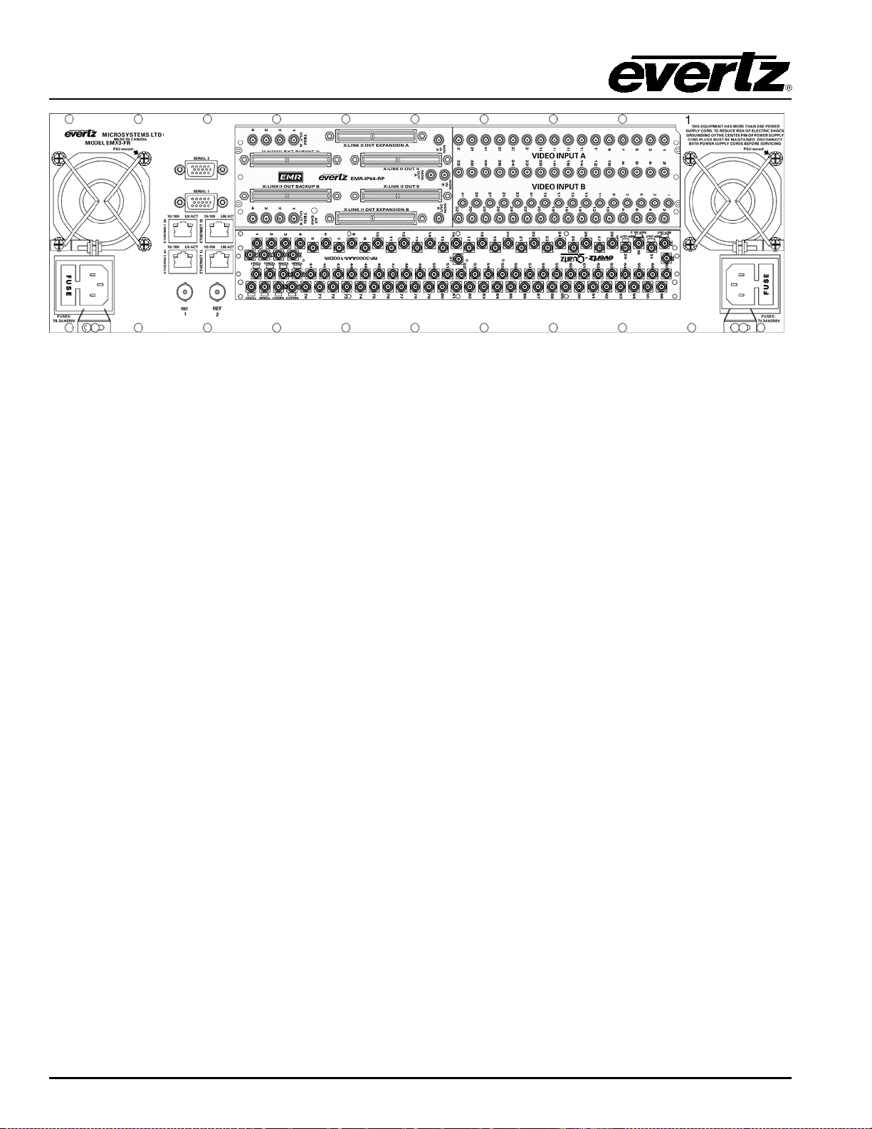
Figure 2-2: EMX3-FR Rear View
2.2. EMR I/O MODULES
The EMR system is b ui lt from a v ariet y of i np ut and out pu t m odu les . A l l mod ul es ar e h ot -sw app abl e an d
can reside in any one of t he 15 slot s of th e EMX6-FR frame or 5 sl ots of th e E M X3-FR frame.
Availab le I/O mod ul es include:
• EMR-IP32H 32 HD/SD inputs with X-Link II outputs
• EMR-IP32-3G 32 3G/HD/SD inputs with X-Link II outputs
• EMR-OP32H 32 HD/SD outputs with X-Link II inputs
• EMR-OP32-3G 32 3G/HD/SD outputs with X-Link II inputs
• EMR-XPT-160X160 Crosspoint with 5 X-Link II inputs and 5 X -Link II outputs
• EMR-XPT-288X288 Crosspoin t w ith 9 X -Link II inputs and 9 X-Link II outputs
Detai l ed mod u l e de s c ri p t i on s , m odu l e r ear p l ate d r awi n g s, an d sp ec i f i c at i on s are p r ov i d ed i n th e fol l owi n g
sections.
2.2.1. EMR Video Input Module
The EMR video input modules consist of 32 channels of adaptive cable equalization that feeds the
incoming signal directly to 3 X-Link II outputs. On each input the cable equalization facility can be
switched on/off as requi red.
Each E MR rear p lat e oc c u p i es 3 s l ot s i n a frame and h a s D I N 1.0/ 2 . 3 con n ec t or s for th e video inputs and
X-Li n k I I ou t p ut s . E ac h r ear p lat e ac c ommod at e s 2 i n p ut car d s w i th al l c on nect or s d esi g nated as A or B .
Th e rear pl at e is p assi ve s o t her e ar e no act ive elec tron ic s on t hem . I f any com pl icat ion s oc cur in t he
fi eld , the f ront module can be repai red or rep laced without the need to d e-cable th e s ystem.
All 3 of the X-Link II outputs are identical, each carrying the 32 output signals from t he card. The X-Link II
outputs are used to drive the input signals to the crosspoint module. Only one c on nec ti on i s req u i r ed pe r
crosspoint.
Page 4 Revision 1.4 COMPONENT OVERVIEW

EMR Video User's Guide
High Density Modular Video Router
Figure 2-3: EMR-IP32H and EMR-IP32-3G Rear Plate
COMPONENT OVERVIEW Revision 1.4 Page 5
EMR Video User's Guide
High Density Modular Video Router
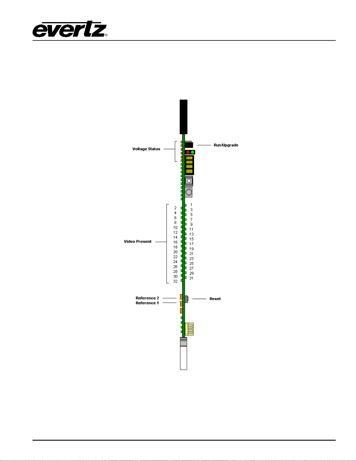
2.2.1.1. Front Card Edge Controls and LE Ds
The EM R-IP32H and E MR-IP32-3G f ront card edge has some key controls and indi cators th at can hel p i n
the installation and debugging processes. Figure 2-4 and Table 2-1 show t h e c ar d ed g e an d d es c ri be th e
expect ed behavior of each component . If t he status in dicat ors do not behave as describ ed i t can be a sign
of i nstal lation or con figuration iss ues.
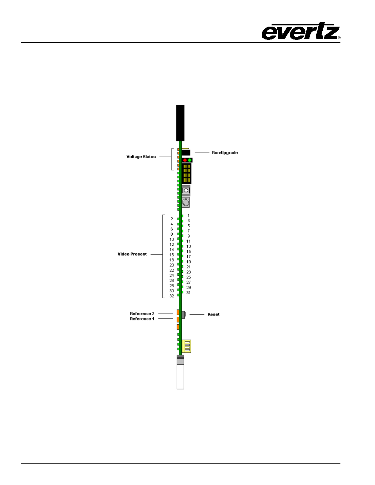
Figure 2-4: EM R Vi de o Input Front Card Edge
Page 6 Revision 1.4 COMPONENT OVERVIEW

EMR Video User's Guide
High Density Modular Video Router
Component Description
Voltage Status LEDs This set of L ED s is amb er in color and should always be ON .
Video Present LEDs
Run/Upgrade Jumper
Reference 1 LED
Reference 2 LED
This set of LEDs is green in color and indicate the presence of video on each
respective input.
This jumper is used to place the module in upgrade mode when upgrading t he
firmware
This LED is amber in color and indicates the presence of a v alid ref erence on
input 1. It will be soli d i f reference is present.
This LED is amber in color and indicates the presence of a v alid ref erence on
input 2. It will be solid if reference is pre sent .
Reset Button This button resets the module.
Table 2-1: Description of EMR Video Input Card Edge
2.2.2. EMR Video Output Module
The EMR video output m odules consist of 32 channels of r e-clocked SD/HD/3G outputs that are sourced
from on e of 2 X -Link I I inputs. The re-clocking function on each path can be switched on/off individually to
facilit ate the passing of ASI v id eo s ig nals.
Each EMR rear plate oc cupies 3 slot s in a frame and has DI N 1.0 /2.3 connectors for the video outputs and
X-Li n k I I i np u t s. E ac h r ear plat e ac c om modat es 2 ou t pu t car ds w i t h al l c on n ec t or s des i gnated as A or B .
Th e rear pl at e is p assi ve s o t her e ar e no act ive elec tron ic s on t hem . I f any com pl icat ion s oc cur in t he
field, the f ront mod ul e can be repaired or replaced without t he need to d e-cable the system.
The 2 X-Link II out puts are designed to be sel ect able, each carrying the 32 input signals to the card. The
X-Link II inputs are used to drive the output signals fr om th e cr ossp oi nt mod ul e. On ly one c on nec t ion is
req uired per cr osspoint.
COMPONENT OVERVIEW Revision 1.4 Page 7
EMR Video User's Guide
High Density Modular Video Router
Figure 2-5: EMR-OP32H and EMR-OP32-3G Rear Plate
Page 8 Revision 1.4 COMPONENT OVERVIEW
EMR Video User's Guide
High Density Modular Video Router
2.2.2.1. Front Card Edge Controls and LE Ds
Th e E MR -OP32H and EMR-OP32-3Gfr ont card edge h a s some key con t rol s an d i n d i c at or s t h at c an hel p
in the installation and debugging process es. Figure 2-6 and Table 2-2 sh ow the card edge and describe
the expec ted behavior of e ach c ompon ent . If the stat us indi cators do not behave as des cribed i t can be a
sign of installation or configuration issues.
Figure 2-6: EM R Vi de o Out put Front Car d Edge
COMPONENT OVERVIEW Revision 1.4 Page 9

EMR Video User's Guide
If the LED is flashing then it indicates that the routed source is from the
This jumper is used to place the module in upgrade mode when upgrading the
LINK II connectors on the rear plate
right convention that
High Density Modular Video Router
Component Description
Voltage Status LEDs This set of LEDs is amber in color and shou ld always b e ON.
This set of LEDs is green in color and i ndicat e the p resenc e of v ide o routed to
each respecti ve output.
Video Present LEDs
If th e LED i s soli d then it indi cates th at th e rout ed sourc e is fr om t he main
crosspoint.
redundant crosspoint.
Run/Upgrade Jumper
Reference 1 LED
Reference 2 LED
Reset Button This button resets the module.
2.2.3. EMR Video Crosspoint Module
Th e E MR -XPT-160X160 and EMR-XPT-288X288 are th e crosspoint cards for the EMR video router. The
EM R c ross poi nt utilizes the v ery lates t technology t o provide a v ery dense r out in g m atr ix, w i th th e f le xibility
of a modular pl atform.
Th e E MR c r os s p oi n t m od ul es u s e th e X -LINK II i nterface to bring signals directl y to the crosspoint and to
supply signals di rectl y from the c rossp oint . This effi cient use of a high densi ty c onnec tor ensur es th at
signal integrity is well maint ained.
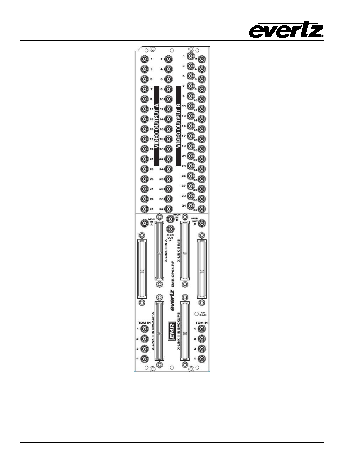
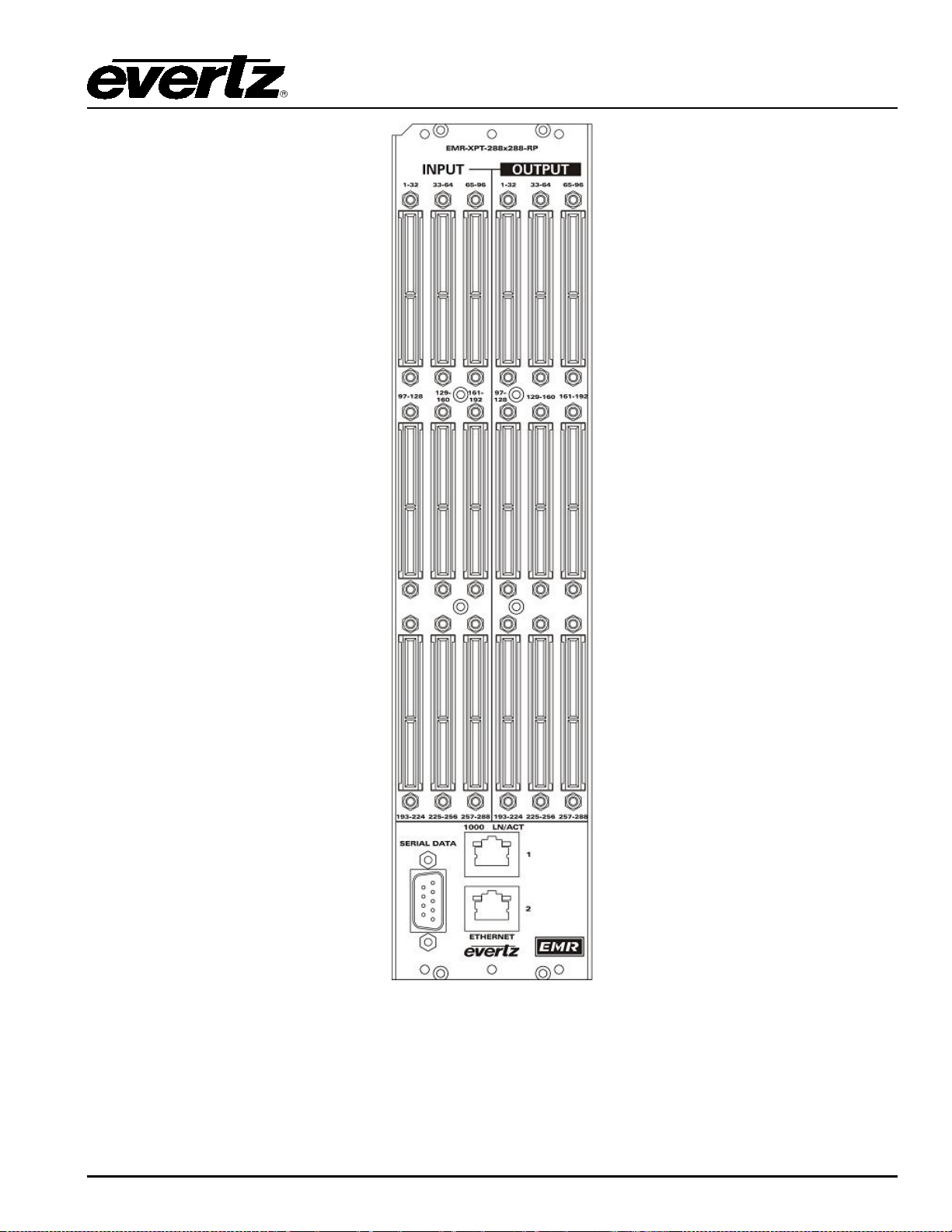
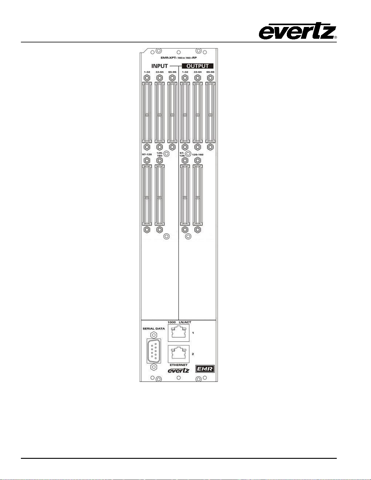
Th e rear pl ate for b oth cros sp oint s oc cup ies 3 sl ots i n a fr am e. T he EM R-XPT-288X288 rear plat e, as
shown in Figure 2-7, has 9 X-Link II inputs and 9 X-Link II outputs, each carrying 32 video signals. The
EMR-XPT-160X160 rear plate, as shown in Figure 2-8, has 5 X-Link II inputs and 5 X-Link II outputs, each
carrying 32 video signal s. Both rear plat es have avai lable Ethernet and serial cont rol options t hat have yet
to be i mplement ed.
firmware.
This LED is am ber in col or an d i nd i c at es t he pr esen c e of a v al i d ref eren ce on
input 1. It will be soli d i f reference is present.
This LED is amb er i n c olor and indicates the p resenc e of a vali d referen ce on
input 2. It will be soli d i f reference is present.
Table 2-2: Description of EMR Video Output Card Edge
Note: The location of the input and output X-
Page 10 Revision 1.4 COMPONENT OVERVIEW
(when viewed from the front) may not correspond to the left-tois often used to place the I/ O cards.
EMR Video User's Guide
High Density Modular Video Router
Figure 2-7: EMR-XPT-288X288 Rear Plate
COMPONENT OVERVIEW Revision 1.4 Page 11
EMR Video User's Guide
High Density Modular Video Router
Figure 2-8: EMR-XPT-160X160 Rear Plate
Page 12 Revision 1.4 COMPONENT OVERVIEW

EMR Video User's Guide
High Density Modular Video Router
2.2.3.1. Front Card Edge Controls and LE Ds
Th e E MR -XPT-160X160 and EMR-XPT-288X2 88 f ron t c ar d edges h ave s o me k ey c ontr ol s an d i n d i c at or s
that can help in the inst allation and debugging process. Figure 2-9 and Table 2-3 show the car d edge and
describe the expected behavior of each com ponent. If the status indicators do not behave as described it
can be a sign of inst allation or configuration issues.
Figure 2-9: EMR Crosspoint Front Card Edge
COMPONENT OVERVIEW Revision 1.4 Page 13
EMR Video User's Guide
High Density Modular Video Router
Component Description
Run/Upgrade Jumper
This jumper is used to place the module in upgrade mode when upgrading
the firmware.
Table 2-3: Description of EMR Crosspoint Card Edge
2.3. EMX-FC FRAME CONTROLLER MODULE
Th e EMX -FC F ram e Cont roll er m odu le pr ovid es a si ngl e poi nt o f acc ess to c omm unic ate w ith th e EMR
cards. The EMX-FC provides a 10Base-T/100Base-TX Ethernet port and handles all communications
between the frame and the contr ol syst em , and serves as a gateway to individual cards in the fr am e. The
EMX-FC also provi des an RS-232 serial port at th e car d edge to set up t he net work add ress es.
Th e E MX -F C i s hou s ed in a narr ow slot underneath th e left side or ri ght side power supply in the EMX6FR frame, and to the l eft of the right side power supply in the EMX3-FR fr ame.
2.4. SC-2000 SYSTEM CONTROLLER
Th e SC-2000 syst em controller is used t o uni fy the individual m odul ar component s of the EMR system
and t o p rov i d e a s i n gl e i n terf ace f or cont r ol an d moni t or i ng . T h e S C -2000 is a 2RU modular chassis th at
has dual hot-swappable redundant power supplies. The chassis is built to accommodate two SC-2000
modules, one for main op eration and one for redundant ope ration. Bot h card s are hot-swappable from th e
front of the chassis. W hen a SC-2000 is ordered, a single c ontroller card and a ch assis are supplied. In
addition, a SC-2000-R can be ordered to add a redundant controller card to the system. In a fully
red undant system, t he t op contr ol card is the main and the bot t om control card is the redundant.
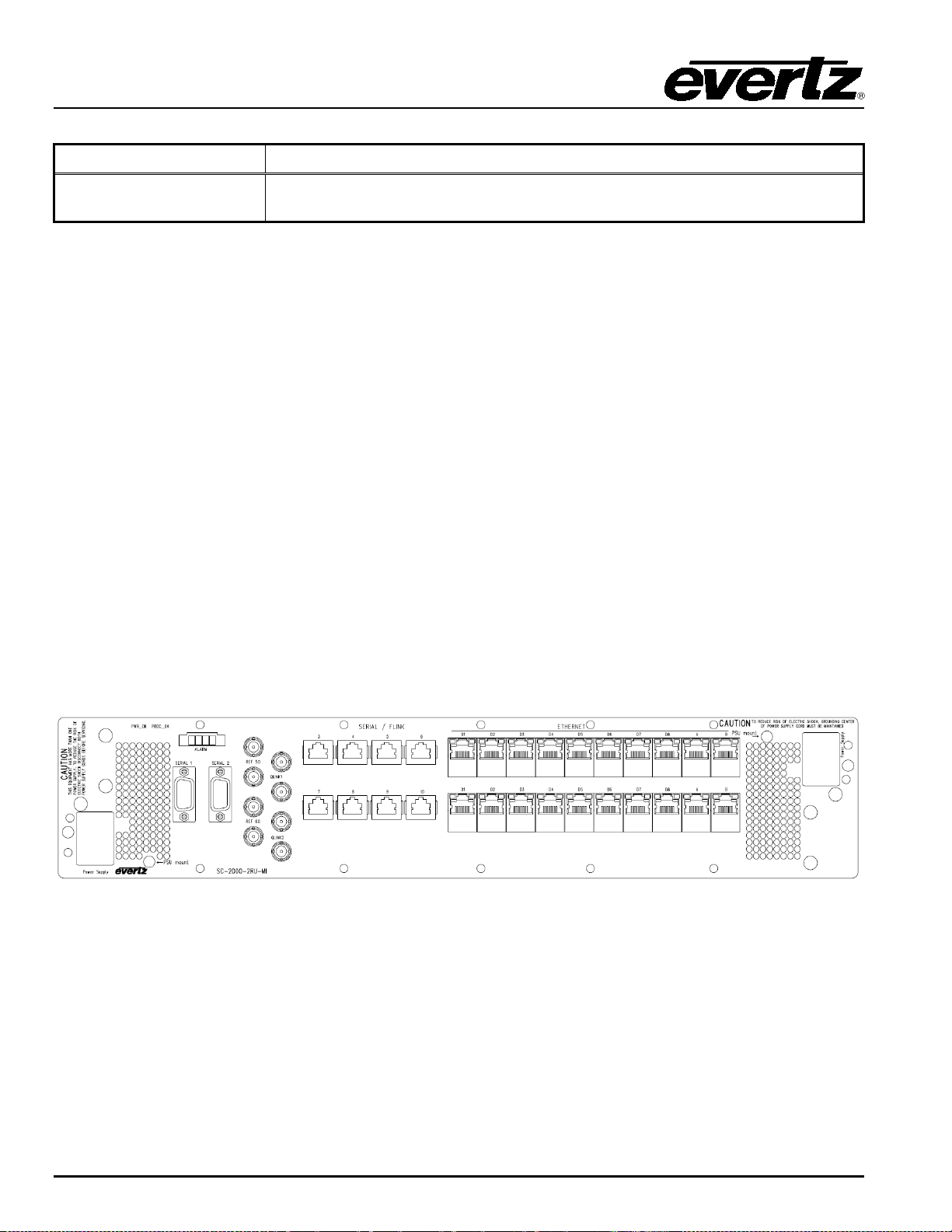
The re ar of the SC-2000 chassis is shown in Figure 2-10.
Figure 2-10: Rear View of SC-2000 Chassis
The SC-2000 has several interfaces with various functions. Some of the interfaces are independent
bet ween th e top and bottom cont roll er cards, and s ome ar e shared betw een t he tw o. Detail s on each
connector are in the following secti on.
Page 14 Revision 1.4 COMPONENT OVERVIEW

EMR Video User's Guide
High Density Modular Video Router
2.4.1. SC-2000 Interfaces Ethernet A: This RJ45 c onnec tor is the c ontrol port for sending c onfigurations to the EMR and
for making crosspoint changes. This port is also used to interface wit h an ext ernal
con t r ol sy s t em to con n ec t r em ot e con t r ol p anel s . E t h ernet p or t A i s i n d ep e n den t f or
each controller card.
Ethernet B: This RJ45 connector is the c ontrol p ort for interfacing the EMR with an ext ernal
SNMP system such as VistaLINK
controll er car d.
Ethernet D: Th i s s et of ei gh t R J 4 5 con n ec t or s ar e u sed to i n t erf ace wi t h e ac h E MX -FC or each
EMX fram e th at consist s of t he ent ire E MR syst em. The D p orts are essent iall y
ports of a switch to allow all of the modular components of the EMR system to
communicate as a single uni t. E thernet ports D are independent for eac h c ont rol l er
card.
Serial 1 & 2: Th es e D 9 con n ect or s are s er ial por t s us ed t o p r ov i d e ser i al con t rol o f t h e S C -2000.
Th e s e ri al p ort s c an be c onf i gu red to be R S -232 or RS-422 using t he conf iguration
sof t w ar e. T h es e s er ial p orts ar e s h ar ed bet ween the m ain and redund ant controller
cards.
Serial/F-Link 3-10: Thes e RJ4 5 connect ors are seri al port s used to pro vide seri al cont rol of the SC-
2000. The serial ports can be configured to be RS-232 or RS-422 using the
configuration software. These serial ports are shared between the main and
red undant cont roller cards.
Q-Link 1 & 2: Thes e tw o Q -LINK 75Ω t erm i nat i on B NC c onn ec tor s s up por t E v ert z c ont r ol p an el s
th at h av e a Q -Li nk con n ect i on. Th e con n ect ors al l ow c on nec t ion to t w o t erm i nat ed
ext ern al Q -Links. Q-L ink is a d edic ated con tr ol s yst em s pec ifi c t o Ever tz bran d o f
Quartz products. The Q-Link system works as a single transmission line with
devices c onnect ed along the length of t he cab le. It must b e ter minat ed at ei th er end
in 75Ω. The two connectors on the rear of the SC-200 have a dedicated loop
through so they must be terminated for them to operate properly. The Q-Link
con nec tors ar e sh ared bet ween th e mai n an d r edund ant con trol ler c ards, w it h the
card in control being the master of the Q-Link.
Ref 1 & 2: T hese t wo 7 5 Ω t er mi n at i on B NC c on n ect or s are u s ed t o p r o v i de a r e f er ence t o t he
SC-2000. Each ref er ence connect or has a l oop t hrough that can be used to loop
the reference through the SC-2000 to the EMR frames in the system. The refer ence
connector s are s hared between the main and redundant cont rol ler cards.
. Ethernet port B is independent for each
®
COMPONENT OVERVIEW Revision 1.4 Page 15
 Loading...