

evertz DreamCatcher Installation Manual

DREAMCATCHER
Replay System
Installation Guide
© Copyright 2016
EVERTZ MICROSYSTEMS LTD.
5292 John Lucas Drive,
Burlington, Ontario, Canada
L7L 5Z9
Phone: +1 905-335-3700 Internet: Sales: sales@evertz.com
Sales Fax: +1 905-335-3573 Tech Support: service@evertz.com
Tech Support Phone: +1 905-335-7570 Web Page: http://www.evertz.com
Tech Support Fax: +1 905-335-7571
Version 1.5, June 2016
The material contained in this manual consists of information that is the property of Evertz Microsystems and is intended
solely for the use of purchasers of DreamCatcher. Evertz Microsystems expressly prohibits the use of this manual for any
purpose other than the operation of the master control switcher.
All rights reserved. No part of this publication may be reproduced without the express written permission of Evertz Microsystems
Ltd. Copies of this guide can be ordered from your Evertz products dealer or from Evertz Microsystems.
All rights reserved. No part of this publication may be reproduced without the express written permission of Evertz
Microsystems Ltd. Copies of this guide can be ordered from your Evertz products dealer or from Evertz Microsystems.

This page left intentionally blank

IMPORTANT SAFETY INSTRUCTIONS
The lightning flash with arrowhead symbol within an equilateral triangle is
intended to alert the user to the presence of uninsulated “Dangerous voltage”
within the product‟s enclosure that may be of sufficient magnitude to constitute
a risk of electric shock to persons.
The exclamation point within an equilateral triangle is intended to alert the user
to the presence of important operating and maintenance (Servicing) instructions
in the literature accompanying the product.
WARNING
TO REDUCE THE RISK OF FIRE OR ELECTRIC – SHOCK, DO NOT EXPOSE THIS APPARATUS
TO RAIN OR MOISTURE
WARNING
DO NOT EXPOSE THIS EQUIPMENT TO DRIPPING OR SPLASHING AND ENSURE THAT NO
OBJECTS FILLED WITH LIQUIDS ARE PLACED ON THE EQUIPMENT
WARNING
TO COMPLETELY DISCONNECT THIS EQUIPMENT FROM THE AC MAINS, DISCONNECT THE
POWER SUPPLY CORD PLUG FROM THE AC RECEPTACLE
WARNING
THE MAINS PLUG OF THE POWER SUPPLY CORD SHALL REMAIN READILY OPERABLE
Read these instructions
Keep these instructions.
Heed all warnings.
Follow all instructions.
Do not use this apparatus near water
Clean only with dry cloth.
Do not block any ventilation openings. Install in accordance with the manufacturer‟s
instructions.
Do not install near any heat sources such as radiators, heat registers, stoves, or other
apparatus (including amplifiers) that produce heat.
Do not defeat the safety purpose of the polarized or grounding-type plug. A polarized plug has
two blades with one wider than other. A grounding-type plug has two blades and a third
grounding prong. The wide blade or the third prong is provided for your safety. If the provided
plug does not fit into your outlet, consult an electrician for replacement of the obsolete outlet.
Protect the power cord from being walked on or pinched particularly at plugs, convenience
receptacles and the point where they exit from the apparatus.
Only use attachments/accessories specified by the manufacturer
Unplug this apparatus during lightning storms or when unused for long periods of time.
Refer all servicing to qualified service personnel. Servicing is required when the apparatus
has been damaged in any way, such as power-supply cord or plug is damaged, liquid has
been spilled or objects have fallen into the apparatus, the apparatus has been exposed to rain
or moisture, does not operate normally, or has been dropped.

INFORMATION TO USERS IN EUROPE
EN60065
Safety
EN504192 2005
Waste electrical products should not be
disposed of with household waste. Contact
your Local Authority for recycling advice
EN55103-1: 1996
Emission
EN55103-2: 1996
Immunity
Evertz Microsystems Ltd
This device complies with part 15 of the FCC Rules.
Operation is subject to the following two conditions:
This device may cause harmful interference, and
This device must accept any interference received,
including interference that may cause undesired
operation.
Tested to comply with
FCC Standards
For Home or Office Use
NOTE
CISPR 22 CLASS A DIGITAL DEVICE OR PERIPHERAL
This equipment has been tested and found to comply with the limits for a Class A digital device,
pursuant to the European Union EMC directive. These limits are designed to provide reasonable
protection against harmful interference when the equipment is operated in a commercial environment.
This equipment generates, uses, and can radiate radio frequency energy and, if not installed and used
in accordance with the instruction manual, may cause harmful interference to radio communications.
Operation of this equipment in a residential area is likely to cause harmful interference in which case
the user will be required to correct the interference at his own expense.
INFORMATION TO USERS IN THE U.S.A.
NOTE
FCC CLASS A DIGITAL DEVICE OR PERIPHERAL
This equipment has been tested and found to comply with the limits for a Class A digital device,
pursuant to Part 15 of the FCC Rules. These limits are designed to provide reasonable protection
against harmful interference when the equipment is operated in a commercial environment. This
equipment generates, uses, and can radiate radio frequency energy and, if not installed and used in
accordance with the instruction manual, may cause harmful interference to radio communications.
Operation of this equipment in a residential area is likely to cause harmful interference in which case
the user will be required to correct the interference at his own expense.
WARNING
Changes or Modifications not expressly approved by Evertz Microsystems Ltd. could void the user‟s
authority to operate the equipment.
Use of unshielded plugs or cables may cause radiation interference. Properly shielded interface
cables with the shield connected to the chassis ground of the device must be used.

DreamCatcher Replay SystemDream Catcher
TABLE OF CONTENTS
1. WELCOME TO THE REVOLUTION ................................................................................. 1
1.1. FEATURES & BENEFITS ................................................................................................ 1
DREAMCATCHER SYSTEM OVERVIEW .................................................................................... 2
2. INSTALLATION ................................................................................................................. 3
2.1. UNPACKING .................................................................................................................... 3
2.1.1. Equipment shipped with every DreamCatcher Server......................................... 3
2.1.2. Equipment shipped with every DreamCatcher Controller .................................... 3
2.2. POWER CONSUMPTION ................................................................................................ 3
2.3. DREAMCATCHER SERVER CONNECTION OVERVIEW ............................................... 4
2.4. DREAMCATCHER PANEL CONNECTION OVERVIEW ................................................. 5
2.5. NETWORK CONNECTION .............................................................................................. 6
2.5.1. Single Server and Controller System Setup ........................................................ 6
2.5.2. Distributed Systems ............................................................................................ 7
2.6. DISPLAYS ..................................................................................................................... 10
2.6.1. Single Server with a Single Controller, Standard Setup .................................... 10
2.6.2. Single Server with Dual Controllers, 4 Monitor Setup ....................................... 10
2.7. GENLOCK ..................................................................................................................... 11
2.8. INPUT/OUTPUTS........................................................................................................... 11
2.9. TIMECODE .................................................................................................................... 17
3. CONFIGURATION ........................................................................................................... 18
3.1. NETWORK CONFIGURATION ...................................................................................... 18
3.1.1. DreamCatcher Server Network Configuration ................................................... 18
3.1.2. DreamCatcher Controller Network Configuration .............................................. 21
3.1.3. DreamCatcher Controller System Configuration ............................................... 24
3.1.4. DreamCatcher Server System Configuration .................................................... 25
3.2. TOUCH SCREEN CONFIGURATION ............................................................................ 31
3.3. CONFIGURATION INTERFACES .................................................................................. 32
3.3.1. Web Configuration ........................................................................................... 32
3.3.2. DreamCatcher Server Settings and Diagnostics Widget .................................. 32
3.3.3. DreamCatcher Controller Settings and Diagnostics Menu ................................ 33
Revision 1.13 Page i

DreamCatcher Replay System
3.4. SYSTEM OPERATION .................................................................................................. 35
3.4.1. Clearing Record Trains and Content ................................................................ 35
3.4.2. Operating Video Standard and Capture Bit Rate .............................................. 36
Figures
Figure 1-1: Dream Catcher Typical System Diagram ....................................................................................... 2
Figure 2-1: Dream Catcher Server Connections .............................................................................................. 4
Figure 2-2: DreamCatcher Panel Connections ................................................................................................. 5
Figure 2-3: DreamCatcher Control Network ..................................................................................................... 6
Figure 2-4: Infrastructure Control Network ....................................................................................................... 7
Figure 2-5: Distributed DreamCatcher Control Networking .............................................................................. 8
Figure 2-6: Distributed Infrastructure Networking ............................................................................................. 9
Figure 2-7: Single Server with a Single Controller - Standard Setup .............................................................. 10
Figure 2-8: Single Server and Dual Controller, 4 Monitor Setup ..................................................................... 11
Figure 2-9: DIN Connectors ............................................................................................................................ 12
Figure 3-1: Server Configuration Login ........................................................................................................... 18
Figure 3-2: Configuration Menu ...................................................................................................................... 18
Figure 3-3: Network Configuration Menu ........................................................................................................ 19
Figure 3-4: Network Configuration Menu ........................................................................................................ 20
Figure 3-5: Controller Settings and Diagnostic Menu ..................................................................................... 21
Figure 3-6: Engineering Menu ........................................................................................................................ 22
Figure 3-7: DC-RCP10 Settings Menu ............................................................................................................ 23
Figure 3-8: Network Interfaces Menu ............................................................................................................. 24
Figure 3-9: DreamCatcher Server IP Menu .................................................................................................... 24
Figure 3-10: Keyboard and Mouse Control Settings Menu ............................................................................. 25
Figure 3-11: DreamCatcher Clip View ............................................................................................................ 26
Figure 3-12: DreamCatcher Clip View part b .................................................................................................. 27
Figure 3-13: DreamCatcher Edit Mode ........................................................................................................... 28
Figure 3-14: DreamCatcher Server System Menu ......................................................................................... 30
Figure 3-15: Touch Screen Configuration Menu ............................................................................................. 31
Figure 3-16: Web Configuration main Page ................................................................................................... 32
Figure 3-17: DreamCatcher Server Settings and Diagnostics Widget ........................................................... 33
Figure 3-18: DreamCatcher Controller Settings and Diagnostics Menu ......................................................... 34
Figure 3-19: DreamCatcher Controller Engineering Menu ............................................................................. 34
Figure 3-20: Data Management Section ......................................................................................................... 35
Figure 3-21: DreamCatcher Configuration ...................................................................................................... 37
Tables
Table 2-1: Possible Configurations in 720p and 1080i ................................................................................... 13
Table 2-2: Possible Configurations in 1080p .................................................................................................. 13
Table 2-3: UHD Configurations ....................................................................................................................... 13
Table 2-4: LTC Pin out .................................................................................................................................... 17
Page ii Revision 1.13

DreamCatcher Replay SystemDream Catcher
REVISION HISTORY
REVISION DESCRIPTION DATE
1.0 Preliminary Release Nov 2013
1.3 Updates Throughout Feb 2015
Information contained in this manual is believed to be accurate and reliable. However, Evertz assumes no responsibility for the use thereof
nor for the rights of third parties, which may be affected in any way by the use thereof. Any representations in this document concerning
performance of Evertz products are for informational use only and are not warranties of future performance, either expressed or implied. The
only warranty offered by Evertz in relation to this product is the Evertz standard limited warranty, stated in the sales contract or order
confirmation form.
Although every attempt has been made to accurately describe the features, installation and operation of this product in this manual, no
warranty is granted nor liability assumed in relation to any errors or omissions unless specifically undertaken in the Evertz sales contract or
order confirmation. Information contained in this manual is periodically updated and changes will be incorporated into subsequent editions. If
you encounter an error, please notify Evertz Customer Service department. Evertz reserves the right, without notice or liability, to make
changes in equipment design or specifications.
Revision 1.13 Page iii

DreamCatcher Replay System
This page left intentionally blank
Page iv Revision 1.13

DreamCatcher Replay SystemDream Catcher
1. WELCOME TO THE REVOLUTION
DreamCatcher is changing the face of production and instant replay. Not only the pioneer of 4K zoom
and Mosaic, DreamCatcher also offers the most robust, scalable and modern IP-based replay system in
the industry today. DreamCatcher‟s rapid editing capabilities combined with enhanced production
workflow allow replay operators to be true craftsman in their profession.
1.1. FEATURES & BENEFITS
Intuitive Touch Interface: DreamCatcher offers an intuitive, customizable graphical user interface for
fast and easy editing. The touch interface provides a modern user experience with drag and drop
capabilities. The user interface reduces the learning curve for novice operators while giving expert
operators a powerful story telling tool.
Integrated Multiviewer: DreamCatcher features a built-in, fully customizable multiviewer for enhanced
replay. Easily configure and view your inputs and outputs. Add and modify smart labels that provide key
information for your editing needs.
Modern: Built on IP based open standards, DreamCatcher offers flexibility and scalability beyond
anything on the market today. With support for dual 1G and dual 10G, DreamCatcher offers the ultimate
networking experience connecting multiple users together to share and collaborate on content.
Everything can be connected within the network, enabling a federated database approach which powers
the search engine.
Built-in Transcoding and Format Conversion: DreamCatcher‟s built-in transcoding engine, supporting
numerous codecs and file wrappers, can easily integrate into most file based workflows. Have multiple
formats? 720p, 1080i, 1080p and UHD? No problem! DreamCatcher makes dealing with multiple formats
a breeze using its integrated conversion tools.
File Based Workflows: DreamCatcher‟s file based workflow allows for seamless integration with all
modern Non Linear Editing software such as Final Cut Pro, AVID and Adobe Premier. This enables the
user to simply extract content, edit the video using one of the NLE‟s and bring it back into DreamCatcher.
Pioneer of 4K Zoom: Go tighter on the action while keeping a crystal clear picture. Deliver an immersive
experience using DreamCatcher‟s advanced capture and zoom technology. With DreamCatcher, the
pioneer of UltraHD 4K replay, capture the action at high frame rates, zoom into multiple points, and freeze
the frame at the critical moment.
High Frame Rate Camera Support: Whether it‟s a 2x slow motion camera or a 10x super slow motion
camera DreamCatcher can support any high frame rate camera.
Revision 1.13 Page 1
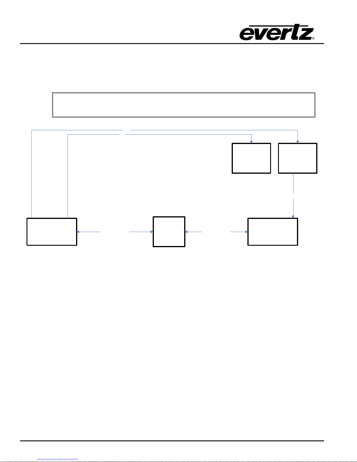
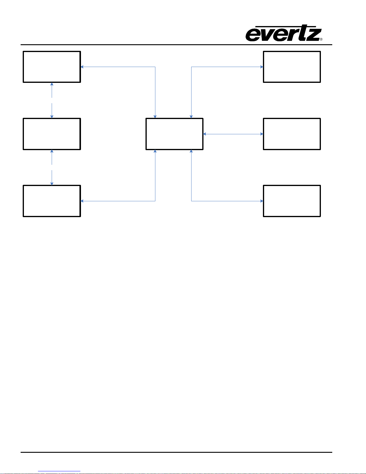
IMPORTANT: Ensure Ethernet 0 is always initialized and ONLY DreamCatcher
Servers and DreamCatcher Controllers are connected to this network.
DreamCatcher
Server 1
DreamCatcher
Controller 1
Monitor Touch Monitor
1G Control
Network
Switch
Control Network Control Network
DVI
DVI
DVIDisplay Port 1
ETH 0
ETH 0/A
USB
USB B
USB A
DreamCatcher Replay System
DREAMCATCHER SYSTEM OVERVIEW
An example of a basic single server/controller setup:
Figure 1-1: Dream Catcher Typical System Diagram
Page 2 Revision 1.13

DreamCatcher Replay SystemDream Catcher
2. INSTALLATION
2.1. UNPACKING
Carefully remove the equipment from the boxes and check against the Packing List supplied with each
unit. This shows what items have been shipped against your order and includes all options. Any error
should be reported to your supplier immediately. After you have unpacked the equipment please save all
the packing material as this could be useful in the future if the unit needs to be returned for maintenance.
Check each item supplied for transit damage. Any damage should be reported in detail to your supplier.
You must state the serial number of the unit (to be found on the rear or side of each unit).
2.1.1. Equipment shipped with every DreamCatcher Server
1. 1x DreamCatcher Server
2. 1x 22” Slide Rail
3. 1x Slide Rail Mounting
4. 1x Display Port to DVI Adapter
5. 2x 10G Copper Twin AX Ethernet Cable
6. 9x DIN to BNC Cables
7. 2x Power Cables
8. 1x RS422/LTC D25 Break Out Cable
2.1.2. Equipment shipped with every DreamCatcher Controller
1. 1x DreamCatcher Controller
2. 1x Power Cables
2.2. POWER CONSUMPTION
DreamCatcher‟s power consumption maximum is 1500W with an average draw of 750W. DreamCatcher
controller‟s power consumption is 65W.
Revision 1.13 Page 3
DreamCatcher Replay System
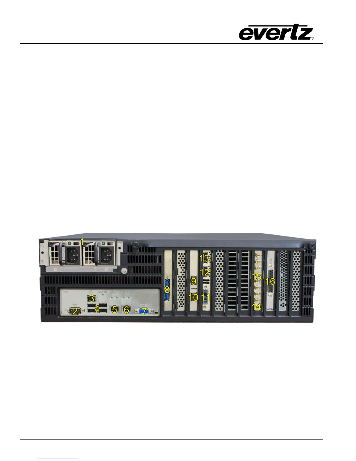
2.3. DREAMCATCHER SERVER CONNECTION OVERVIEW
Error! Reference source not found.1 below shows the available connections for DreamCatcher
1. Redundant power supplies
2. Serial Port - Currently unused
3. IPMI Port - Currently unused
4. 4x USB 2.0 Ports
5. ETH 0 - 1G DreamCatcher Communication Network
6. ETH 1 - 1G Infrastructure Network
7. VGA Port - Currently unused
8. 2x USB 3.0 Ports
9. ETH 2 – 10G Distributed Network
10. ETH 3 – 10G Redundant Distributed Network
11. DVI Port
12. Display Port 1
13. Display Port 2
14. Reference In
15. 8x Inputs/Outputs
16. RS-422 Connector
Figure 2-1: DreamCatcher Server Connections
Page 4 Revision 1.13
DreamCatcher Replay SystemDream Catcher
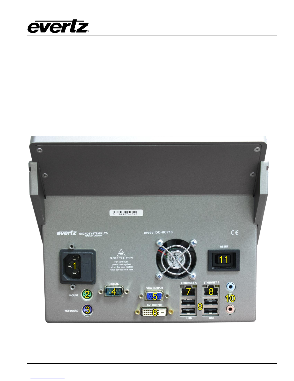
2.4. DREAMCATCHER PANEL CONNECTION OVERVIEW
Figure 2-2 below shows the available connections for DreamCatcher‟s Controller
1. Power supply
2. PS2 Mouse
3. PS3 Keyboard
4. Serial Port – Currently unused
5. VGA Port
6. DVI Port
7. ETH A – 1G DreamCatcher Communication Network
8. ETH B – 1G Infrastructure Network
9. 4x USB 2.0
10. Audio – Currently unused
11. Reset Button
Figure 2-2: DreamCatcher Panel Connections
Revision 1.13 Page 5

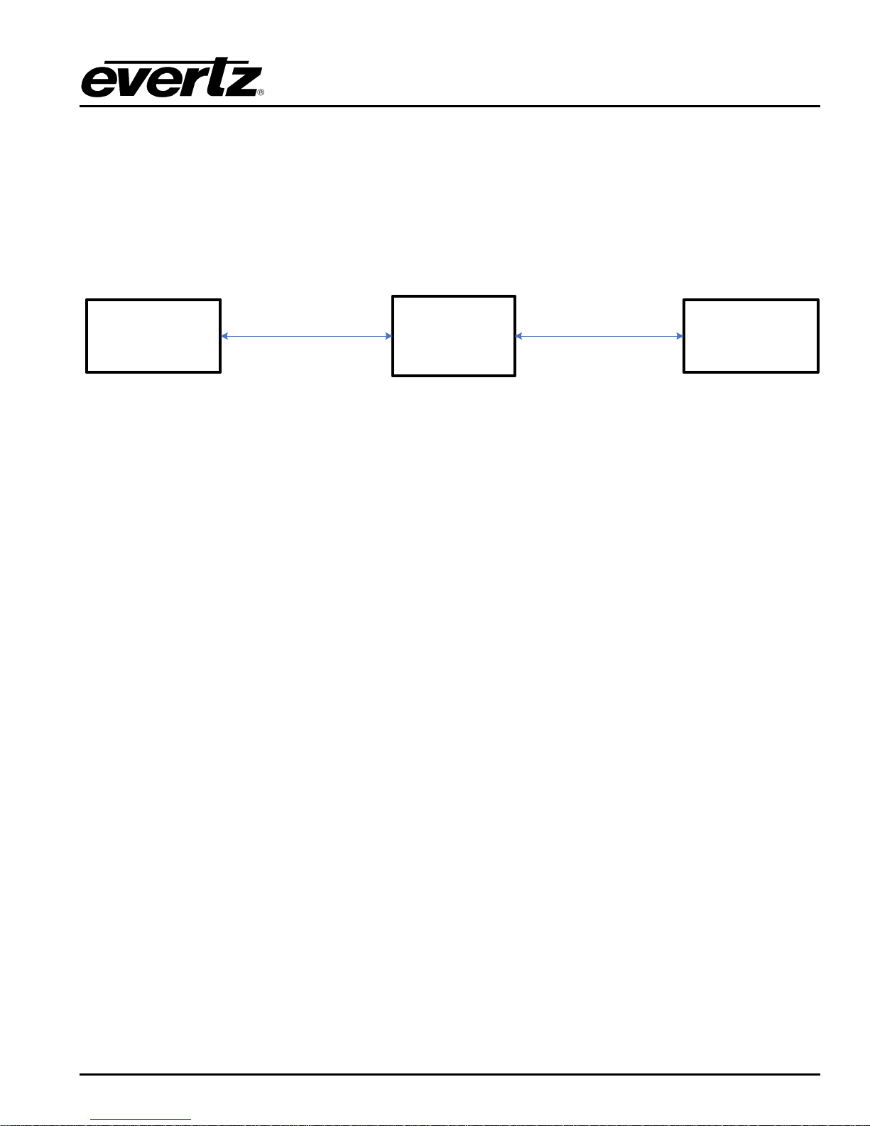
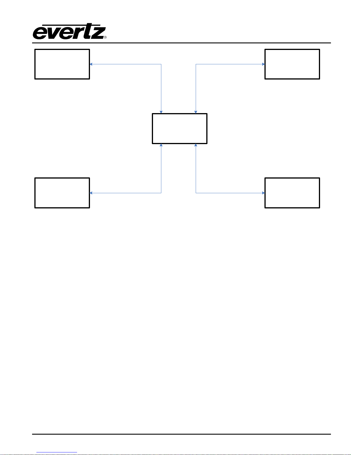
IMPORTANT: Ensure Ethernet 0 is always initialized and ONLY DreamCatcher
Servers, DreamCatcher Controllers and DC-LOGGERS are connected to this
network.
DreamCatcher
Server 1
DreamCatcher
Controller 1
1G Isolated
DreamCatcher
Network
ETH 0
ETH 0/A
(Optional)
DC-LOGGER
ETH 0
DreamCatcher Replay System
2.5. NETWORK CONNECTION
2.5.1. Single Server and Controller System Setup
Required equipment:
DreamCatcher Server
DreamCatcher Controller
Optional 1G Network Switch (Control Network)
Optional 1G Network Switch (Infrastructure Network)
Cat5/Cat5e/Cat6 Cables
Procedure:
Use Figure 2-1, Figure 2-2, Figure 2-3 and Figure 2-4 as reference.
Connect Ethernet 0 on DreamCatcher to Ethernet A/0 on the Controller directly or through a 1G
Network Switch.
Figure 2-3: DreamCatcher Control Network
Page 6 Revision 1.13
DreamCatcher Replay SystemDream Catcher
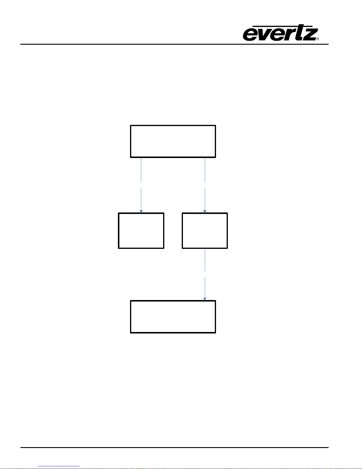
DreamCatcher
Server 1
DreamCatcher
Controller 1
1G Infrastructure
Network Switch
ETH 1
ETH 1/B
If DreamCatcher and it‟s Controller need to interact with other infrastructure equipment (i.e. routers,
production switchers and engineering PCs) add a second 1G Ethernet switch. This infrastructure
network is generally used to communicate with Routers, Production Switches and Engineering PCs.
Connect Ethernet 1 on DreamCatcher to the 1G Infrastructure switch.
Connect Ethernet B/1 on the Controller to the 1G Infrastructure switch.
Figure 2-4: Infrastructure Control Network
2.5.2. Distributed Systems
Required equipment:
2 or more DreamCatcher Servers
2 or more DreamCatcher Controllers
1G Network Switch (Control Network)
10G Network Switch
Optional 1G Network Switch (Infrastructure Network)
Procedure:
Use Figure 2-1, Figure 2-2 and Figure 2-5 as reference.
Connect Ethernet 0 on all DreamCatcher servers to the 1G DreamCatcher Control Switch.
Connect Ethernet A/0 on all DreamCatcher controllers to the 1G DreamCatcher Control Switch.
Connect Ethernet 2 on all DreamCatcher Servers to the IPX 10G switch.
If you are distributing only 2 DreamCatcher Servers it is possible to connect the servers directly over
the Ethernet 2 10G port.
Revision 1.13 Page 7
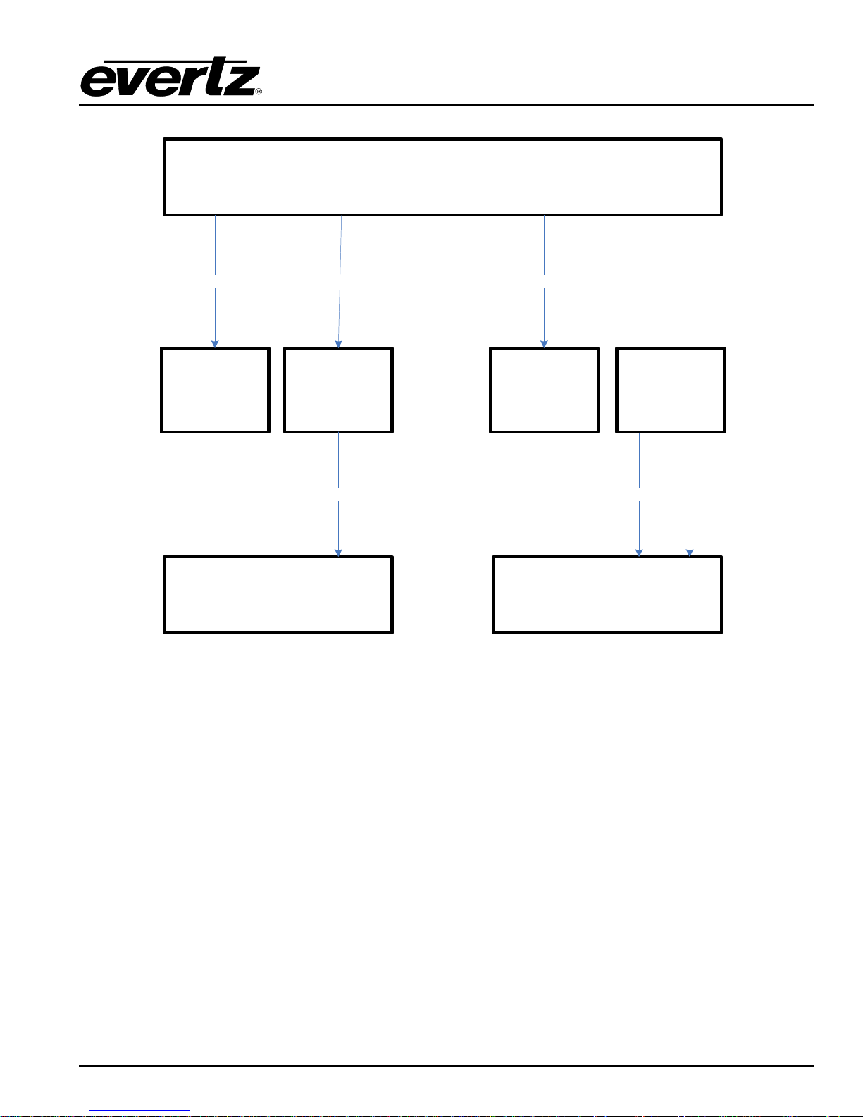
DreamCatcher
Controller 1
ETH 0
DreamCatcher
Controller 2
DC-LOGGER
DreamCatcher
Server 1
10G IPX Switch
(When connecting 3
or more systems)
DreamCatcher
Server 2
1G Isolated
DreamCatcher
Network
10G
10G
ETH 0
ETH 0
ETH 0
ETH 0
ETH 2
ETH 2
DreamCatcher Replay System
Figure 2-5: Distributed DreamCatcher Control Networking
Use Figure 2-1, Figure 2-2 and Figure 2-6 as reference.
If DreamCatcher needs to interact with other infrastructure equipment (i.e. routers, production
switcher and engineering PCs) add a second 1G Ethernet switch.
Connect Ethernet 1 on all DreamCatcher servers to the 1G Infrastructure switch.
Connect Ethernet B/1 on all DreamCatcher Controllers to the 1G Infrastructure switch.
Page 8 Revision 1.13
DreamCatcher Replay SystemDream Catcher
DreamCatcher
Controller 1
DreamCatcher
Controller 2
DreamCatcher
Server 1
DreamCatcher
Server 2
1G Infrastructure
Network Switch
ETH 1
ETH 1
ETH 1
ETH 1
Figure 2-6: Distributed Infrastructure Networking
Revision 1.13 Page 9
DreamCatcher Server 1
DreamCatcher Controller 1
Monitor Touch Monitor
DVI DVI
DVI Display Port 1
USB
USB B
USB A
DreamCatcher Replay System
2.6. DISPLAYS
2.6.1. Single Server with a Single Controller, Standard Setup
Required equipment:
DreamCatcher Server
DreamCatcher Controller
2x Displays or Optional Touch Displays
Figure 2-7: Single Server with a Single Controller - Standard Setup
2.6.2. Single Server with Dual Controllers, 4 Monitor Setup
Required equipment:
DreamCatcher Server
2x DreamCatcher Controller
2x Standard Displays
2x Displays or Optional Touch Screen Displays
Page 10 Revision 1.13
DreamCatcher Server 1
DreamCatcher Controller 2
Monitor Touch Monitor
DVI DVI
DVI Display Port 1
USB
USB B
USB A
DreamCatcher Controller 1
Monitor Touch Monitor
USB
DVI
DVI
Display Port 2
USB B
USB A
DreamCatcher Replay SystemDream Catcher
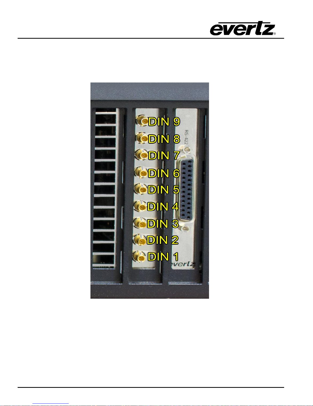
2.7. GENLOCK
DreamCatcher currently requires a Black Burst reference signal. Plug the reference signal into DIN 1 at
the back of DreamCatcher as shown on Figure 2-1 and Figure 2-9.
To check the reference standard follow the setup in section 3.3.1 and section 3.4.2.1 to get to
DreamCatcher‟s Configuration page. Once on the page you should see reference detected as NTSC or
PAL.
2.8. INPUT/OUTPUTS
DreamCatcher‟s Inputs and Outputs can be dynamically configured using the web configuration
application. For this reason the labelling on the back of DreamCatcher may not be accurate. Using Figure
2-1, follow these general rules for cabling inputs and outputs.
Connect output 1 to the DIN connector immediately adjacent to the reference signal connector. In
Figure 2-1 this would be the second DIN from the bottom.
Figure 2-8: Single Server and Dual Controller, 4 Monitor Setup
Revision 1.13 Page 11
DreamCatcher Replay System
The remaining outputs will connect incrementally following output 1.
The first input connection will be connected to the DIN immediately following the last output.
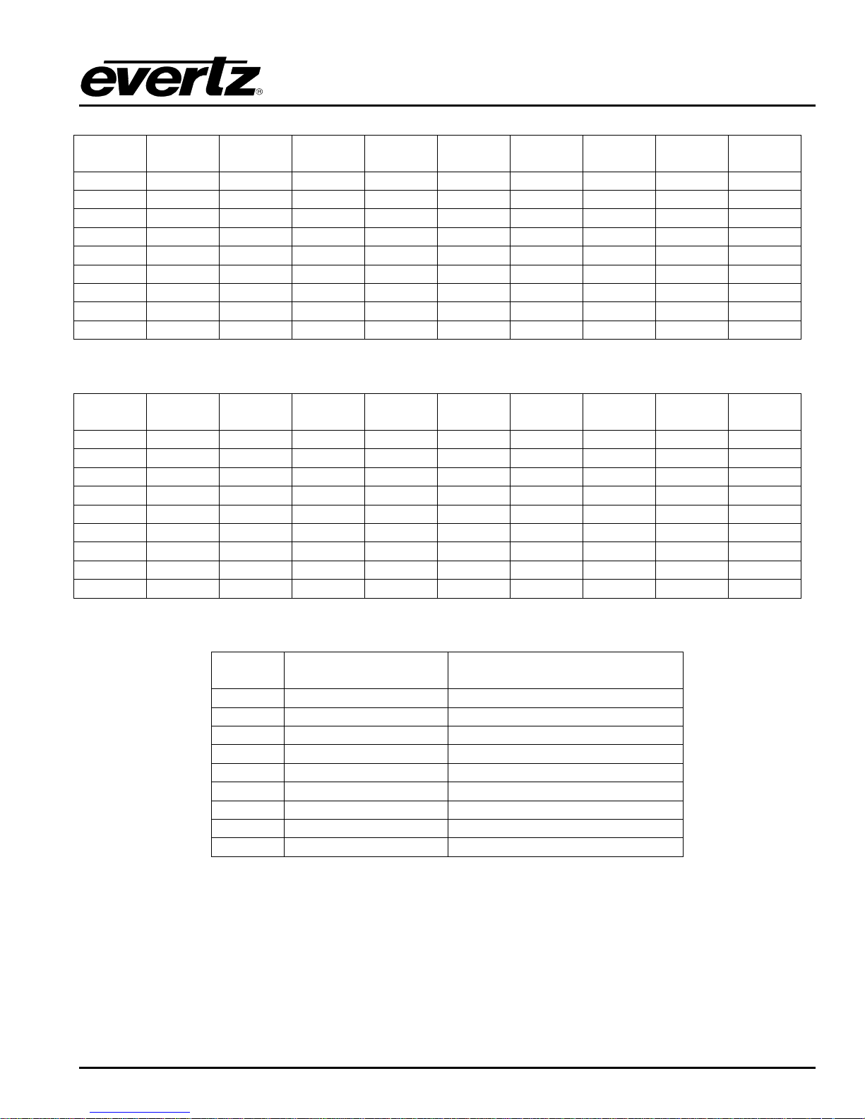
Use Figure 2-9 and Table 2-1, Table 2-2 and Table 2-3 below for all possible Input/Output
configurations.
Page 12 Revision 1.13
Figure 2-9: DIN Connectors
0 IN x
8 OUT
1 IN x
7 OUT
2 IN x
6 OUT
3 IN x
5 OUT
4 IN x
4 OUT
5 IN x
3 OUT
6 IN x
2 OUT
7 IN x
1 OUT
8 IN x
0 OUT
DIN 9
OUT 9
IN 1
IN 2
IN 3
IN 4
IN 5
IN 6
IN 7
IN 8
DIN 8
OUT 7
OUT 7
IN 1
IN 2
IN 3
IN 4
IN 5
IN 6
IN 7
DIN 7
OUT 6
OUT 6
OUT 6
IN 1
IN 2
IN 3
IN 4
IN 5
IN 6
DIN 6
OUT 5
OUT 5
OUT 5
OUT 5
IN 1
IN 2
IN 3
IN 4
IN 5
DIN 5
OUT 4
OUT 4
OUT 4
OUT 4
OUT 4
IN 1
IN 2
IN 3
IN 4
DIN 4
OUT 3
OUT 3
OUT 3
OUT 3
OUT 3
OUT 3
IN 1
IN 2
IN 3
DIN 3
OUT 2
OUT 2
OUT 2
OUT 2
OUT 2
OUT 2
OUT 2
IN 1
IN 2
DIN 2
OUT 1
OUT 1
OUT 1
OUT 1
OUT 1
OUT 1
OUT 1
OUT 1
IN 1
DIN 1
REF
REF
REF
REF
REF
REF
REF
REF
REF
0 IN x
4 OUT
1 IN x
4 OUT
2 IN x
4 OUT
3 IN x
4 OUT
4 IN x
4 OUT
4 IN x
3 OUT
4 IN x
2 OUT
4 IN x
1 OUT
4 IN x
0 OUT
DIN 9
NA
NA
NA
NA
IN 4
NA
NA
NA
NA
DIN 8
NA
NA
NA
IN 3
IN 3
IN 4
NA
NA
NA
DIN 7
NA
NA
IN 2
IN 2
IN 2
IN 3
IN 4
NA
NA
DIN 6
NA
IN 1
IN 1
IN 1
IN 1
IN 2
IN 3
IN 4
NA
DIN 5
OUT 4
OUT 4
OUT 4
OUT 4
OUT 4
IN 1
IN 2
IN 3
IN 4
DIN 4
OUT 3
OUT 3
OUT 3
OUT 3
OUT 3
OUT 3
IN 1
IN 2
IN 3
DIN 3
OUT 2
OUT 2
OUT 2
OUT 2
OUT 2
OUT 2
OUT2
IN 1
IN 2
DIN 2
OUT 1
OUT 1
OUT 1
OUT 1
OUT 1
OUT 1
OUT 1
OUT 1
IN 1
DIN 1
REF
REF
REF
REF
REF
REF
REF
REF
REF
1 UHD IN x 1 UHD
OUT
1 UHD IN x 2 1080P OUT
DIN 9
QUADRANT 4 IN
NA
DIN 8
QUADRANT 3 IN
NA
DIN 7
QUADRANT 2 IN
QUADRANT 4 IN
DIN 6
QUADRANT 1 IN
QUADRANT 3 IN
DIN 5
QUADRANT 4 OUT
QUADRANT 2 IN
DIN 4
QUADRANT 3 OUT
QUADRANT 1 IN
DIN 3
QUADRANT 2 OUT
1080 P FULL RASTER OUT 2
DIN 2
QUADRANT 1 OUT
1080 P ZOOM OUT 1
DIN 1
REF
REF
DreamCatcher Replay SystemDream Catcher
Table 2-1: Possible Configurations in 720p and 1080i
Table 2-2: Possible Configurations in 1080p
Table 2-3: UHD Configurations
2.9. INPUT/OUTPUTS FOR HIGH DENSITY SYSTEM
A second karak card can be added to DreamCatcher‟s Inputs and Outputs. It can be dynamically
configured using the web configuration application. For this reason the labelling on the back of
DreamCatcher may not be accurate. With a high density system you have 2 sets of DIN connections. The
left side represents the inputs and right side represents the outputs. The reference DIN connections
Revision 1.13 Page 13

IMPORTANT: You will need both Reference DINS (Left and Right) plugged in. Also,
ensure that 1 of the XLR connections on each breakout cable are connected
to get timecode.
DreamCatcher Replay System
remain the bottom two DIN. The most that can be done are 10in x 4out in a HD setup, and 8in x 2out on
1080P setup, Using 2-4, follow these general rules for cabling inputs and outputs.
Connect output 1 to the DIN connector immediately adjacent to the reference signal connector. In
Figure 2-10 this would be the second DIN from the bottom.
The remaining outputs will connect incrementally following output 1.
Figure 2-10: High Density DIN Connectors
Page 14 Revision 1.13
 Loading...