

Page 1

Model 5700MSC
Master Clock System
Quick Start Guide
© Copyright 2017
EVERTZ MICROSYSTEMS LTD.
5292 John Lucas Drive
Burlington, Ontario
Canada L7L 5Z9
Phone: +1 905-335-3700
Sales: [email protected] Fax: +1 905-335-3573
Tech Support: [email protected] Fax: +1 905-335-7571
Web Page:
Version 1.0, Januar y 2017
The material contained in this manual consists of information that is the property of Evertz Microsyst ems and is intended solely for t he use of
purchasers of the 5700MSC Master Clock product. Evertz Microsystems expressly prohibits the use of this manual for any purpose other t han
the operation of the 5700MSC Maste r Clock product. Due to on going research and developm ent, features and s pecifications in thi s manual
are subject to change without notice.
All rights reserved. No part of this publicat ion m ay be reproduced without the express writt en perm ission of Evertz Mic rosys tems Ltd. Copies
of this manual can be ordered from your Evertz dealer or from Evertz Microsystems.
http://www.evertz.com
Page 2

This page left intentionally blank
Page 3
IMPORTANT SAFETY INSTRUCTIONS
WARNING
SHOCK, DO NOT EXPOSE THIS APPARATUS
TO RAIN OR MOISTURE
WARNING
DO NOT EXPOSE THIS EQUIPMENT TO DRIPPING OR SPLASHING AND ENSURE THAT NO
OBJECTS FILLED WITH LIQUIDS A RE PLACED ON THE EQUIPMENT
WARNING
TO COMPLETELY DISCONNECT THIS EQUIPMENT FROM THE AC MAINS, DISCONNECT T HE
POWER SUPPLY CORD PLUG FROM THE AC RECEPTACLE
WARNING
THE MAINS PLUG OF THE POWER SUPPLY CORD SHALL REMAIN READILY OPERABLE
The lightning flash with arrowhead symbol within an equilateral triangle is
intended to alert the user to the presence of uninsulated “Dangerous voltage”
within the product’s enclosure that may be of sufficient magnitude to
constitute a risk of electric shock to persons.
The exclamation point within an equilateral triangle is intended to alert the
user to the presence of important operating and maintenance (Servicing)
instructions in the literature accompanying the product.
• Read these instructions
• Keep these instructions.
• Heed all warnings.
• Follow all instructions.
• Do not use this apparatus near water
• Clean only with dry cloth.
• Do not block any ventilation openings. Install in accordance with the manufacturer’s instructions.
• Do not install near any heat sources such as radiators, heat registers, stoves, or other apparatus
(including amplifiers) that produce heat.
• Do not defeat the safety purpose of the polarized or gr ounding-type plug. A polarized plug has t wo
blades with one wider than other. A grounding-type plug has two blades and a third grounding
prong. The wide blade or the third prong is provided for your safety. If the provided plug does not
fit into your outlet, consult an electrician for replacement of the obsolete outlet.
• Protect the power cord from being walked on or pinched particularly at plugs, convenience
receptacles and the point where they exit from the apparatus.
• Only use attachments/accessories specified by the manufacturer
• Unplug this apparatus during lightning storms or when unused for long periods of time.
• Refer all servicing to qualified service personnel. Servicing is required when the apparatus has
been damaged in any way, such as power-supply cord or p lug is damaged, liquid has been spill ed
or objects have fallen into the apparatus, the apparatus has been exposed to rain or moisture, does
not operate normally, or has been dropped.
TO REDUCE THE RISK OF FIRE OR ELECT RIC –
Page 4
EN60065
Safety
EN55103-1: 1996
Emission
EN55103-2: 1996
Immunity
INFORMATION TO USERS IN EUROPE
NOTE
CISPR 22 CLASS A DIGITAL DEVICE OR PERIPHERAL
This equipment has been tested and found to comply with the limits for a Class A digital device,
pursuant to the European Union EMC directive. These limits are designed to provide reasonable
protection against harmful interference when the equipment is operated in a commercial environment.
This equipment generates, uses, and can radiate radio frequency energy and, if not installed and used
in accordance with the instruction manual, may cause harmful interference to radio communications.
Operation of this equipment in a residential area is likely t o cause harmful interference in which case
the user will be required to correct the interference at his own expense.
Waste electrical products should not
be disposed of with household waste.
EN504192 2005
Contact your Local Authority for
recycling advice
INFORMATION TO USERS IN THE U.S.A.
NOTE
FCC CLASS A DIGITAL DEVICE OR PERIPHERAL
This equipment has been tested and found to comply with the limits for a Class A digital device,
pursuant to Part 15 of the FCC Rules. These limits are designed to provide reasonable protection
against harmful interference when the equipment is operated in a commercial environment. This
equipment generates, uses, and can radiate radio frequency energy and, if not installed and used in
accordance with the instruction manual, may cause harmful interference to radio communications.
Operation of this equipment in a residential area is likely t o cause harmful interference in which case
the user will be required to correct the interference at his own expense.
WARNING
Changes or Modifications not expressly approved by Evertz Microsystems Ltd. could void the user’s
authority to operate the equipment.
Use of unshielded plugs or cables may cause radiation interference. Properly shielded interface
cables with the shield connected to the chassis ground of the device must be used.
Page 5

Model 5700MSC
Master Clock System
REVISION HISTORY
REVISION DESCRIPTION DATE
1.0 First Release Jan 2017
Information contained in this manual is beli eved to be accurate and reliable. However, Evertz assumes no res ponsibility for the use thereof
nor for the rights of third parties, which may be af fected in any way by the use thereof. Any representations in this document concerning
performance of Evertz products are for informational us e only and are not warranties of f uture perf ormance, either express ed or impli ed. The
only warranty offered by Evertz in relation to this product is the Evertz standard limited warranty, stated in the sales contract or order
confirmation form.
Although every attempt has been made to accurately describe the features, installation and operation of this product in this manual, no
warranty is granted nor liability as sumed in relation to any errors or om issions unless specific ally undertaken in the Evertz s ales contract or
order confirmation. Information contained in this manual is periodically updated and changes will be incorporated into subsequent editi ons. If
you encounter an error, please notify Evertz Customer Service department. Evertz reserves the right, without notice or liabilit y, to make
changes in equipment design or specifications.
Revision 1.0 Page - i
Page 6

Model 5700MSC
Master Clock System
This page left intentionally blank
Page - ii Revision 1.0
Page 7

Model 5700MSC
Master Clock System
TABLE OF CONTENTS
1. OVERVIEW ................................................................................................................................... 1
1.1. MOUNTING AND POWER CONNECTIONS ......................................................................... 1
1.2. FRONT PANEL INSTALLATION .......................................................................................... 1
1.3. CONFIGURING THE ETHERNET PORTS ............................................................................ 2
1.4. SELECTING AND CONNECTING FREQUENCY REFERENCES ........................................ 2
1.5. SELECTING AND CONNECTING TIM E REFERENCES ...................................................... 3
1.6. CHECKING THE STATUS OF THE UNIT ............................................................................. 4
1.7. WIRING THE OUTPUTS ....................................................................................................... 4
1.8. CONFIGURING THE SYNC OUTPUTS ................................................................................ 5
1.9. CONFIGURING THE TEST GENERATOR OUTPUTS ......................................................... 5
1.10. CONFIGURING THE TIME OUTPUTS ................................................................................. 5
1.11. FINAL STEPS OF SET UP AND SECURING ALL CONNECTIONS .................................... 6
1.12. ACCESS CONTROL ............................................................................................................. 6
Figures
Figure 1-1: 5700MSC Front Panel.................................................................................................................... 1
Figure 1-2: 5700MSC Rear Panel View ........................................................................................................... 4
Revision 1.0 Page - iii
Page 8

Model 5700MSC
Master Clock System
This page left intentionally blank
Page - iv Revision 1.0
Page 9
Model 5700MSC
Master Clock System
1. OVERVIEW
The guide provides steps on how to setup and configure a 5700MSC.
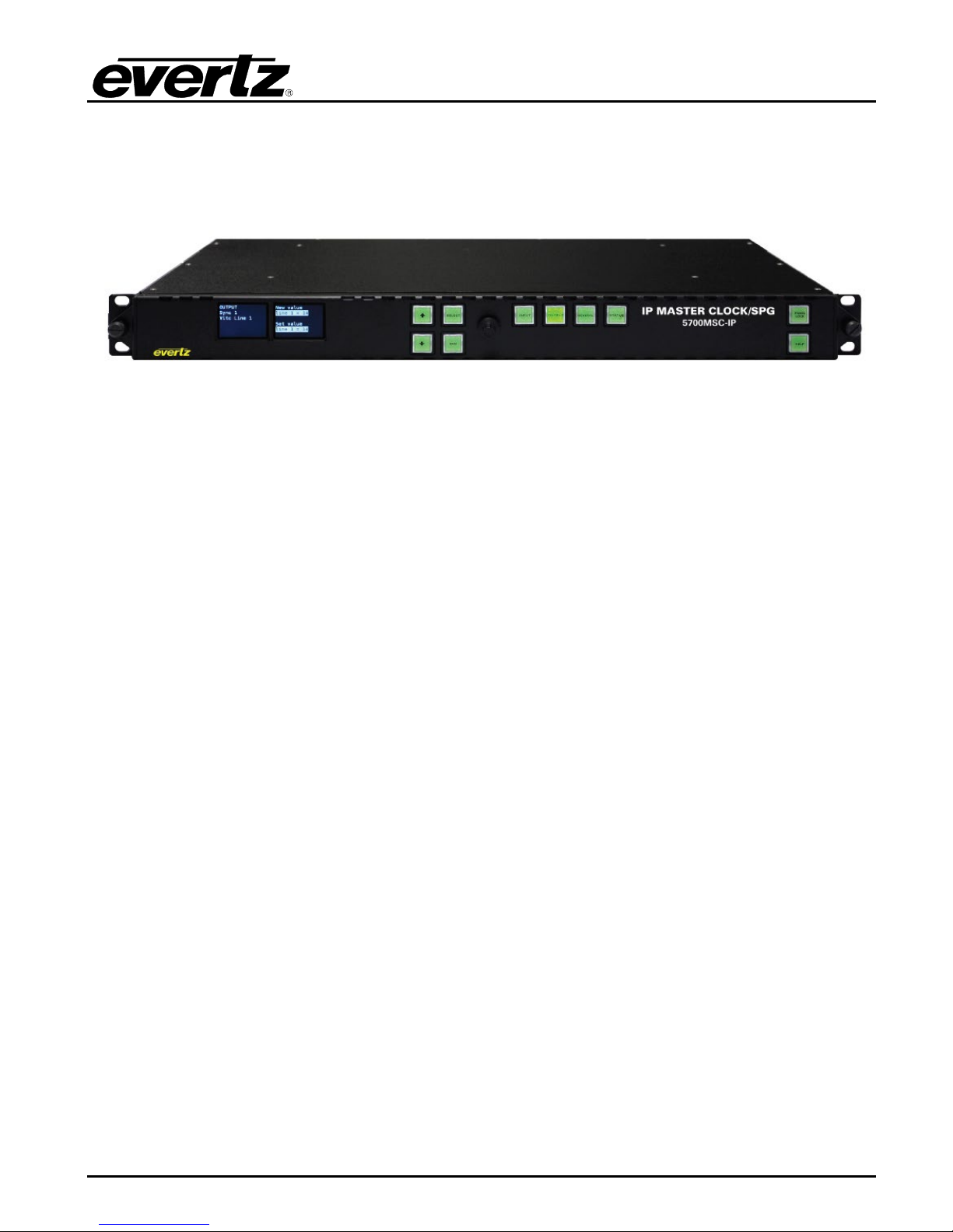
Figure 1-1: 5700MSC Front Panel
1.1. MOUNTING AND POWER CONNECTIONS
The 5700MSC chassis holds the main board, one power supply, and one fan module. Dual power
supplies are an available option in which case a sec ond power supply replaces the fan module. The
chassis has built-in rack mounting ears and fit s in a standard 19” rack. Two fans on each side cool the
unit. Clearance of 2” (5cm) must be maintained around the fan exhausts on either side of the chassis.
The power supply operates from an AC line frequency of 50Hz to 60Hz, at 100V-240V (aut o-sensing).
The fan module does not require AC power to function. The power consumption of a 5700MSC is 125
Watts with all options installed.
If dual power supplies are fitted, they should both be supplied with AC power. Each power supply has
its own IEC C14 AC power inlet. The inlets are isolated from each other and can be powered by the
same AC power source but ideally should be powered from different AC sources for true redundancy.
If both supplies are not powered, the unpowered supply will trig ger a system fault. A redundant power
supply may be added at any time to a unit by removing the fan module and installing the second power
supply.
The power supplies and fan module are hot swappable and accessed from the front of the unit by
removing the front panel. Each power supply and fan module has a Phillips mounting screw at the
front that can be used to secure the module in order to prevent accidental removal.
1.2. FRONT PANEL INSTALLATION
The 5700MSC comes with a removable front panel that is equipped with two color LCD screens, along
with 10 pushbuttons, and a control knob for navigating the menu system and configuring the unit. The
front panel is secured by the two thumbscrews on either end. The fr ont panel can be removed and reinstalled while the unit is running to provide access to the power supplies and for troubleshooting
purposes. When re-installing the front panel be sure to fully tighten the thumb screws.
When AC power is applied to the 5700MSC and the power supplies are switched on, the unit will start
up automatically. The front panel should become operative within approximately 30 seconds.
Revision 1.0 Page - 1
Page 10

Model 5700MSC
Master Clock System
1.3. CONFIGURING THE ETHERNET PORTS
Press the GENERAL button on the front panel to access the general setup menu. This menu can be
used to configure the two Ethernet ports on the 5700MSC. Both the GigE 1 port and the GigE 2 port
are used for SNMP monitoring and control of the unit.
The current menu selection will be indicated by the > character. Rotate the control knob or press the
and buttons to select the IP Control menu item and press the SELECT button or depress the k nob.
Assign an unused IP address and subnet mask to the GigE 1 and/ or GigE 2 ports. The two ports must
be on separate subnets in order to function properly. When entering an IP address, the contr ol knob
can be used to set each octet. Depress the control knob while turning to adjust in larger steps. The
Ethernet link status and current IP settings can be viewed by pressing the STATUS button and
selecting the Ethernet GigE 1 or the Ethernet GigE 2 status screens.
If SNMP monitoring or control of the unit is desired, the SNMP feature must first be enabled (it is
disabled by default). Select the GENERAL menu and press ESC to return to the root menu. Scroll
down to EngineeringMenu and press SELECT. A password is required to enable the engineering
menu items. Press SELECT on Password and use the and buttons or control knob to enter each
digit of the numeric password and then press SELECT. The default password is 5700. The SNMP
menu should now be accessible and SNMP can be enabled through SNMP Ctl. The trap addresses
must be assigned if SNMP traps are required to be sent to remote logging software such as
VistaLINK® Pro. Contact Evertz customer service if a MIB to the 5700MSC is required.
1.4. SELECTING AND CONNECTING FREQUENCY REFERENCES
Pressing the INPUT button on the front panel will select the input menu. From here the frequency and
time references of the unit can be configured. Use the control knob to select the Frequency Ref menu
item and press SELECT or depr ess the knob. The Reference Src m enu item selects six diff erent ways
the 5700MSC can lock its master oscillator.
• GNSS Mobile – The 5700MSC will look for a Global Navigation Satellite System (GNSS)
antenna attached to the GPS port on the back of the unit. This mode is intended for applications
where the location of the GNSS antenna is movable such as mobile production trucks. Start-up
time before receiving data is optimized assuming the location may have changed from the
previous time.
• GNSS Fixed – T he 5700MSC will look for a GNSS antenna attached to the GPS port on the
back of the unit. This mode is intended for applications where the location of the GNSS antenna
is fixed. Start-up time before receiving data will be longer the first time the unit is first powered
up as the antenna determines the fixed location. Subsequent start-up times will be shorter as
the unit assumes the GPS location has not changed from the previous time.
The GPS Enable and GLONASS Enable menu items in the Engineering Menu control
whether the receiver will lock to satellites from the GPS and/or GLONASS Global
Navigation Satellite Systems.
Page - 2 Revision 1.0
Page 11

Model 5700MSC
Master Clock System
With either the GNSS Mobile or GNSS Fixed menu choices, the ovenized oscillator inside the
5700MSC will lock to the 1PPS pulse from the GNSS antenna. This provides a very accurate
frequency reference to the unit. The high precision time and date provided by the GNSS
antenna is used to phase the outputs of the 5700MSC by referencing them to a specific point in
GNSS time. Multiple 5700MSC units locked to GNSS will all have the same phase on their
outputs. This also means the time reference will be forced to GNSS.
• Ten MHz – The 5700MSC will look for a 5MHz or 10MHz reference on its reference loop input,
frame reference 1, or frame reference 2. The 5MHz/10MHz reference should come from a
source that has higher stability than the internal oscillator of the 5700MSC such as a Rubidium
or Caesium frequency standard. A 5MHz or 10MHz reference does not provide any phase
information and the phase of the outputs will not be the same between different 5700MSC units.
• Video – T he 5700MSC will genlock to an analog black burst or HD tri-level reference applied to
its reference loop input, frame reference 1, or frame reference 2. The frequency stability of the
5700MSC will be only as good as that of the reference input. The phase of the outputs will be
aligned to that of the reference input.
• Internal – The 5700MSC will free run on its internal high stability ovenized oscillator. Select this
option if no external reference is available to the unit.
• 1588 – The 5700MSC can synchronize with a PTP master to determine a frequency reference.
There are three other menu items that control how the 5700MSC locks to its reference. These are
Genlock Range, Genlock Source, and Lock type. Press the HELP button for a short description on
what each menu item does.
1.5. SELECTING AND CONNECTING TIM E REFERENCES
Once the desired frequency reference has been selected and the antenna/reference connect ions have
been made, the time reference should be selected. The time reference is how the 5700MSC obtains
time and date for the system clock. Press the INPUT button t o access the input menu. Return to the
root level by pressing ESC a few times. Select the Time menu using the control knob and press
SELECT. Use the Reference Src menu item t o choose a time reference for the unit. There are other
menu items that control how the 5700MSC handles the time reference. Press the HELP button to
identify the function of each item.
• GNSS – W hen a GPS or GLONASS receiver is connected to the unit, it c an obtain continuous
time and date updates from GNSS. If the frequency reference has been set to one of the G NSS
modes, the time reference will also be forced to GNSS. However it is also possible to use a
frequency reference other than GNSS (such as video) and still use GNSS as a very accurate
time reference. See note above regarding GLONASS operation.
• VITC – The 5700MSC will look for Vertical Interval Time Code on the selected line of a black
burst signal that is applied to the reference loop input, frame reference 1, or frame reference 2.
It can also decode date information from the user bits in several dif ferent form ats. In order to
use VITC as a time reference, the frequency reference must first be set to Video.
Revision 1.0 Page - 3
Page 12
Model 5700MSC
Master Clock System
• None – The 5700MSC will not acquire time from any outside source. The time and date must be
manually entered using the front panel in the GENERAL m enu. The high frequency stability of
the unit and battery backup will ensure the 5700MSC keeps fairly accurate time.
• SNTP – The 5700MSC can synchronize once daily to time and date from an NTP server.
• 1588 – The 5700MSC can synchronize with a PTP master to determine the time and date.
1.6. CHECKING THE STATUS OF THE UNIT
After the input references are connected and set up, the status of t he unit can be checked by pressing
the STATUS button on the front panel. There are several different status screens which can be
selected by using the control knob or the and buttons. The status of the frequency and time
references can be viewed by choosing the Lock status screen and pressing SELECT. Press ESC to
return to the status menu to select another screen for viewing. Any screen name that is highlighted with
a red or yellow background indicates that one of the statuses in that screen is in a fault or warning
condition.
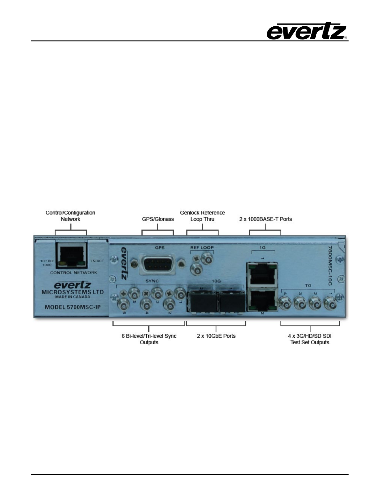
Figure 1-2: 5700MSC Rear Panel View
1.7. WIRING THE OUTPUTS
Most outputs are provided as Mini-BNC connectors and wiring is straightforward. The GigE 1 and GigE
2 ports use a standard RJ-45 connector, and the 10GbE ports require an SFP10G-TR13-A (not
included).
Page - 4 Revision 1.0
Page 13

Model 5700MSC
Master Clock System
1.8. CONFIGURING THE SYNC OUTPUTS
The sync outputs of the 5700MSC are configured in the OUTPUT menu, accessed by pressing the
OUTPUT button. All sync outputs are derived from the master oscillator and will be locked in frequency
and phase. The sync outputs are all programmable to output several different sync types and can be
phased independently from each other.
In the OUTPUT menu, the sync outputs are configured using the SYNC 1 to SYNC 6 sub-menus.
Each sync output can set to output any number of black burst or HD tri-level standards. They are all
phased independently. When configuring a sync output, the mode must be selected first. By default,
the mode of all sync outputs are set to NTSC-M black bur st f or North American units , and PAL-B black
burst for European units. Configure the mode of each sync output to the format desired for the
installation.
There are numerous other configuration settings for each sync output, some may be disabled (dark
text) or enabled (white text) depending on the output mode selected. Scroll over each of the available
menu items and press the HELP button for more information on the function of each menu item.
1.9. CONFIGURING THE TEST GENERATOR OUTPUTS
The unit has been equipped with four video test generators on Mini-BNC outputs. Each g enerator can
output a number of SDTG, HDTG, or 3GTG options. These are configured in the TG 1, TG 2, TG 3,
and TG4 menus. All test generators are derived from the master oscillator and will be automatically
locked in frequency and phase. The test generators are independent from one another and can be
configured to different formats and different phase offsets. By default, all phases will be aligned to the
selected frequency reference.
The unit also has two 10GbE ports that can output test generators if the +10G-TG option is ordered.
Each 10GbE port can output 3 test generators, which can be configured in the TG 5, IP 1a; TG6, IP1b;
TG7, IP1c; TG8, IP2a; TG9, IP2b; and TG10, IP 2c menus.
The quickest and easiest way to discover how to configure the outputs is to scroll through the available
menu items and press the HELP button for a description of each menu item function.
1.10. CONFIGURING THE TIME OUTPUTS
All time outputs from the unit come from the System Time clock. This clock can be vie wed by pressing
the STATUS button and selecting the System/In time screen. When the time reference is obtained
from a GNSS sources, the system time will be Coordinated Universal Time (UTC). UTC time is the
same at all locations around the world.
In order to output local time, the Time Zone must be selected to match the time zone offset of your
location. For example, in North America, Eastern Standard Time (EST) is UTC –5:00 hours. Central
Standard Time (CST) is UTC –6:00 hours. Mountain Standard Time (MST) is UTC –7:00 hours. Pacific
Standard Time is UTC –8:00 hours. The 5700MSC also supports Daylight Savings Time, which must
be enabled separately for each time output. Below are descriptions of the time outputs available from
the 5700MSC.
• Sync Outputs – When a Sync output mode is set to NTSC-M or PAL-B black burst, VIT C time
can be inserted onto two lines in the vertical blanking interval. The VITC is controlled by the Vitc
Revision 1.0 Page - 5
Page 14

Model 5700MSC
Master Clock System
Ctl, Vitc Line 1, Vitc Line 2, Dropf rame Ctl, Color Frame, Set Jam Time, Jam O utput, Jam all
Vitc, Time offset, Tim e Zone, and DST enable menu items.
• Server Protocols – The 5700MSC will support Network Time Protocol and Precision Time
Protocols. These are configured by pressing the GENERAL button and entering the NTP rules,
PTP All ports, PTP GigE 1, PTP GigE 2, PTP 10G 1, and PTP 10G 2 sub-menus. The
5700MSC hosts an NTP server and also sends out periodic NTP broadcasts. NTP time should
always be UTC. PTP broadcast rates are determined using the PTP sub-menus listed above.
• Test Generator Outputs – Timecode can be “burned-in” at the bottom of any of the the
5700MSC test signal outputs. These are configured by pressing the OUTPUT button and
entering the appropriate TG menu. The time is controlled by the TC Burn In, Dr opframe Ctl, Set
Jam Time, Jam Output, Jam all VitcLtc, Time Offset, Time Zone, and DST enable sub-menu
items.
1.11. FINAL STEPS OF SET UP AND SECURING ALL CONNECTIONS
Once the 5700MSC has been configured, the various STATUS screens should be checked to ensure
there are no items displayed with a red or yellow background. The left LCD screen should show “Sys
OK” and “Ref OK” with a green background in the bottom corners.
The power supply and fan modules (accessed by removing the front panel) should be secured to the
chassis by fastening the Phillips mounting screw. The GPS D-Sub connector on the back of the unit
should be secured to the 5700MSC using mounting screws. The AC power cords can be fixed to the
unit using the retaining clips provided.
1.12. ACCESS CONTROL
The engineering menu password can be changed from the default to prevent unauthorized tampering
of SNMP and menu access control settings. The SNMP Ctl menu item can be changed to SNMP off or
SNMP status t o prevent remote SNMP control of the unit. Furthermore, pressing the PANEL LOCK
button can lock the front panel. This prevents accidental changes by someone bumping or leaning into
the front panel. The front panel can be unlocked by pressing the SELECT and PANEL LOCK buttons
simultaneously.
Page - 6 Revision 1.0
 Loading...