


Frame Manual
500DA2Q-3G 3G/HD/SD-SDI Dual Reclocking Distribution Amplifier
TABLE OF CONTENTS
1. OVERVIEW.......................................................................................................................................... 1
2. INSTALLATION................................................................................................................................... 3
3. SPECIFICATIONS............................................................................................................................... 4
3.1. SERIAL VIDEO INPUT............................................................................................................... 4
3.2. SERIAL VIDEO OUTPUTS......................................................................................................... 4
3.3. ELECTRICAL ............................................................................................................................. 4
3.4. PHYSICAL.................................................................................................................................. 4
4. STATUS LEDS.................................................................................................................................... 5
4.1. INPUT 1 INDICATORS............................................................................................................... 5
4.2. INPUT 2 INDICATORS............................................................................................................... 6
5. LOCATION OF LEDS AND JUMPERS .............................................................................................. 7
5.1. SELECTING WHETHER LOCAL FAULTS WILL BE MONITORED
BY THE GLOBAL FRAME STATUS.......................................................................................... 7
5.2. SELECTING NON-RECLOCK MODE........................................................................................ 8
6. VISTALINK® REMOTE MONITORING/CONTROL............................................................................. 9
6.1. WHAT IS VISTALINK®?............................................................................................................. 9
6.2. MONITOR SETTINGS TAB...................................................................................................... 10
6.2.1. Lock Status ......................................................................................................................... 10
6.2.2. Bypass Select ..................................................................................................................... 10
6.2.3. Input Video Rate ................................................................................................................. 11
6.3. FAULT TRAPS TAB................................................................................................................. 11
6.3.1. Module OK Trap Status....................................................................................................... 11
Figures
Figure 1-1: 500DA2Q-3G Block Diagram..............................................................................................................2
Figure 2-1: 500DA2Q-3G Rear Panel Overlay......................................................................................................3
Figure 5-1: LED and Jumper Locations ................................................................................................................7
Figure 5-1: VistaLINK® 500DA-3G Monitor Status Tab.......................................................................................10
Figure 5-1: VistaLINK® 500DA-3G Fault Traps Tab............................................................................................11
Revision 2.0

Frame Manual
500DA2Q-3G 3G/HD/SD-SDI Dual Reclocking Distribution Amplifier
REVISION HISTORY
REVISION
1.0 Original Version Apr 2009
2.0 Updated for rev 2 hardware, added input 2 locked LED and corrected Jan 2011
jumper labels
Information contained in this manual is believed to be accurate and reliable. However, Evertz assumes no responsibility for the use thereof nor for
the rights of third parties, which may be affected in any way by the use thereof. Any representations in this document concerning performance of
Evertz products are for informational use only and are not warranties of future performance, either expressed or implied. The only warranty offered
by Evertz in relation to this product is the Evertz standard limited warranty, stated in the sales contract or order confirmation form.
Although every attempt has been made to accurately describe the features, installation and operation of this product in this manual, no warranty is
granted nor liability assumed in relation to any errors or omissions unless specifically undertaken in the Evertz sales contract or order confirmation.
Information contained in this manual is periodically updated and changes will be incorporated into subsequent editions. If you encounter an error,
please notify Evertz Customer Service department. Evertz reserves the right, without notice or liability, to make changes in equipment design or
specifications.
DESCRIPTION DATE
Revision 2.0

Frame Manual
500DA2Q-3G 3G/HD/SD-SDI Dual Reclocking Distribution Amplifier
1. OVERVIEW
The 500DA2Q-3G Dual 3G/HD/SD-SDI Reclocking Distribution Amplifier provides the highest density DA
in the industry allowing up to 32-3Gb/s, HD-SDI or SD-SDI Distribution amplifiers in a 3RU rack space.
This module provides inexpensive distribution of your SMPTE 424M (3Gb/s), SMPTE 292M (1.5Gb/s),
SMPTE 259M (270Mb/s), DVB-ASI or SMPTE 310M (19.4Mb/s) or any other SDI signal within the
143Mb/s to 1.5Gb/s range.
The 500DA2Q-3G features two auto-equalized inputs and can be individually set via jumpers for either
reclocking or non-reclocking.
The 500DA2Q-3G is housed in the 500FR exponent frame that will hold up to 16 modules.
Features:
• Normal reclocked mode for SMPTE 424M (3Gb/s), SMPTE 292M (1.5Gb/s) and SMPTE 259M
(270Mb/s)
• Jumper selectable non-reclocked mode for all other SMPTE 344M, SMPTE 259M, SMPTE 310M and
DVB-ASI data rates
• Fully hot-swappable from front of frame with no BNC disconnect required
• Independent isolated output drivers to ensure no cross channel loading effects (i.e. no need to
terminate unused outputs)
• Outputs maintain polarity from input to output for DVB-ASI applications
• Tally output on Frame Status bus upon loss of input signal for quality monitoring
• VistaLINK
frame with 500FC VistaLINK
-capable for remote monitoring via SNMP (using VistaLINK® PRO) when installed in 500FR
®
Frame Controller
®
Input:
• 2 inputs
• SMPTE 424M (3Gb/s), SMPTE 292M (1.5Gb/s), SMPTE 259M (270Mb/s) when set to re-clocking
mode.
• SMPTE 344M (540Mb/s), SMPTE 259 (360Mb/s, 143Mb/s), SMPTE 310M (19.4Mb/s), DVB-ASI when
not re-clocking
• Return Loss > 15dB to 1.5GHz and > 10dB up to 3GHz
• Auto equalization to 80m at 3Gb/s, 140m @ 1.5Gb/s and 350m @ 270Mb/s
Outputs:
• 4 reclocked outputs per input
• Return Loss > 15dB to 1.5GHz
• Wideband jitter < 0.2 UI
Card Edge LEDs:
• Reclocker rate (3 LEDS)
• Reclocker locked
• Reclocker bypass
• Module Health Status
Revision 2.0 Page - 1
Frame Manual
500DA2Q-3G 3G/HD/SD-SDI Dual Reclocking Distribution Amplifier
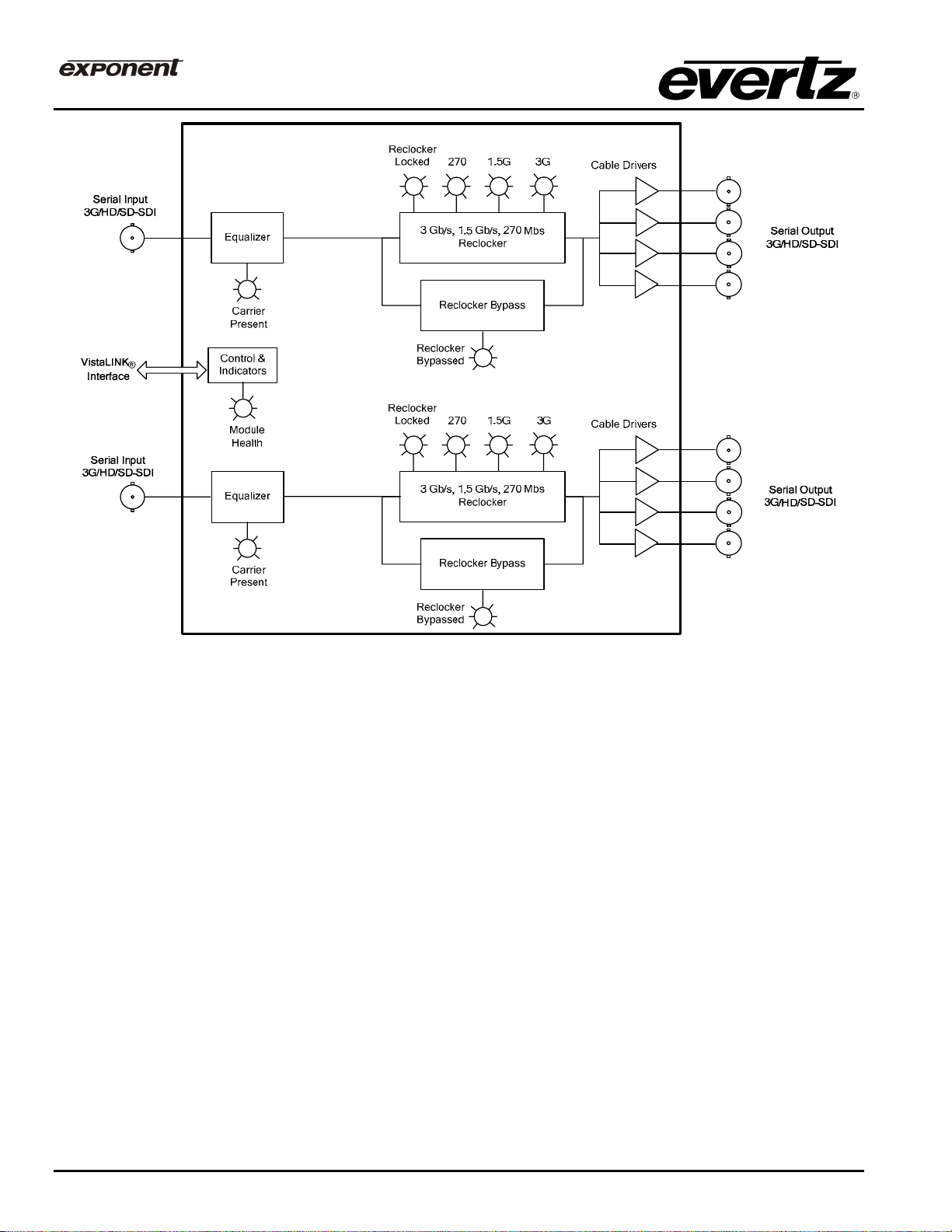
Figure 1-1: 500DA2Q-3G Block Diagram
Page - 2 Revision 2.0

Frame Manual
500DA2Q-3G 3G/HD/SD-SDI Dual Reclocking Distribution Amplifier
2. INSTALLATION
The 500DA2Q-3G comes with a companion rear panel overlay that can be placed over the rear panel
BNC connectors to identify their function. For information on inserting the module into the frame see
section 3 of the 500FR chapter.
Figure 2-1: 500DA2Q-3G Rear Panel Overlay
IN A & IN B: Input BNC connectors for 10-bit serial digital video signals compatible with the
SMPTE 292M, SMPTE 259M, SMPTE 344M and SMPTE 310M (19.4 Mb/s)
standards or any SDI signal between the range of 143Mb/s to 1.5 Gb/s.
OUT 1A to 4A: These four BNC connectors are used to output reclocked serial component video
from IN (A).
OUT 1B to 4B: These four BNC connectors are used to output reclocked serial component video
from IN (B).
Revision 2.0 Page - 3
 Loading...