

SF804-0 Smoke Detector
Installation Instructions
General Introduction
The SF804-0 Smoke Detector is designed to sense smoke that comes into the
detector’s chamber. It does not sense gas, heat, or flame. When it detects a
certain density of smoke the horn will sound and the RF module will emit signals
to the Gateway. Its great compatibility with our U-Net family security products
makes it suitable for smart home cloud based platforms such as Homesys.
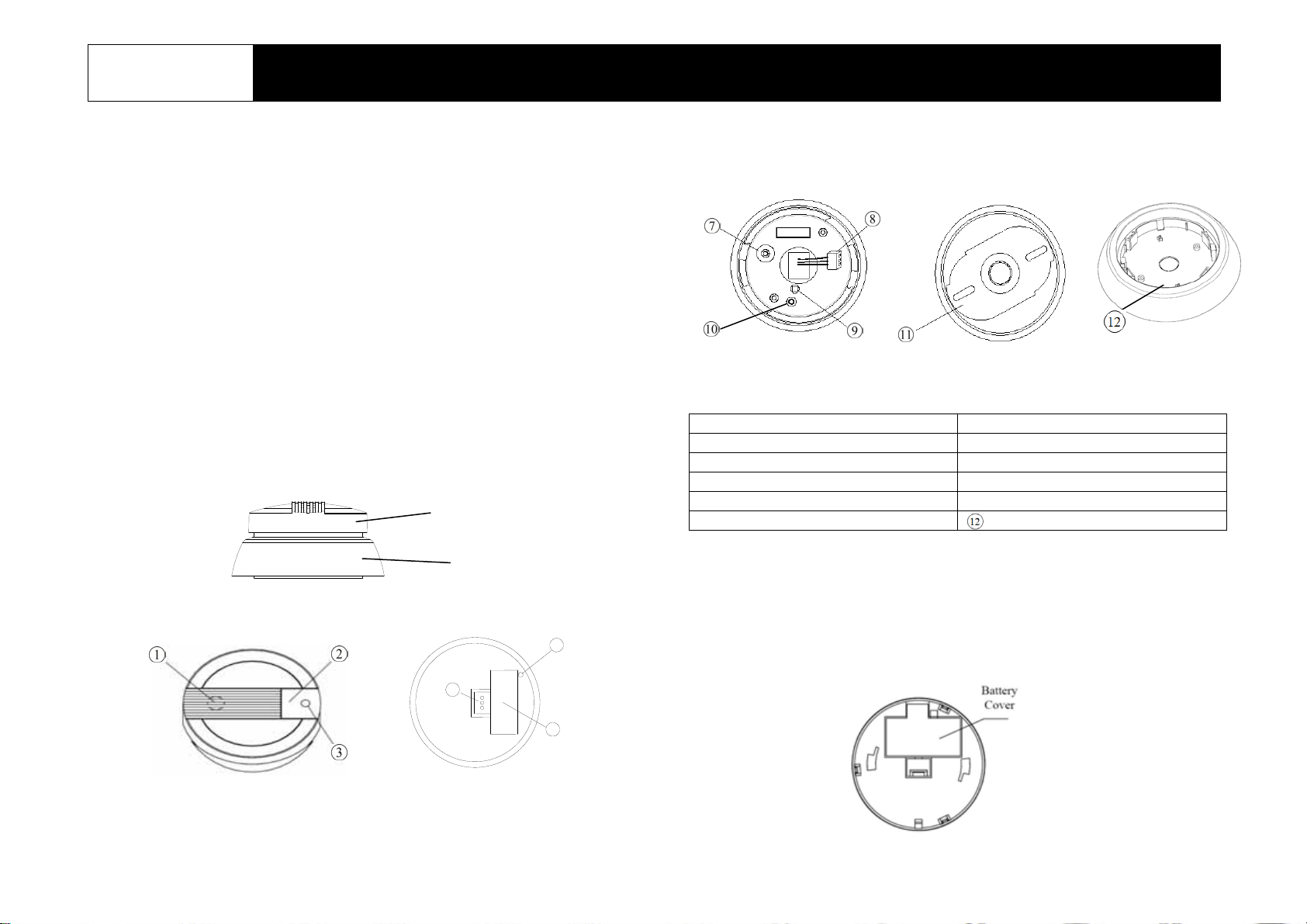
Product Layout
The sensor consists of two parts; a sen sor module and a transmitte r module The
transmitter module can be detached by twisting it clockwise against the sensor
module.
Sensor Module : Front and Back view
Sensor module
Transmitter module
5
4
6
Transmitter module: Front and Back view
Horn Tamper switch
Test Button Connector
Smoke LED Learning key
Connector pins ○10 Link LED
Cover Latch ⑪ Mounting bracket
Battery Cover Skirt Panel
Binding with Homesys
1. Twist the transmitter module clockwise to detach it from the sensor module
2. Disconnect the connector from the connector pins of the sensor module.
Take note of the connector direction as you will need to connect it back later.
3. Open the battery cover.
1
4. Prepare one 9V alkaline battery. Do not insert it into the unit yet.
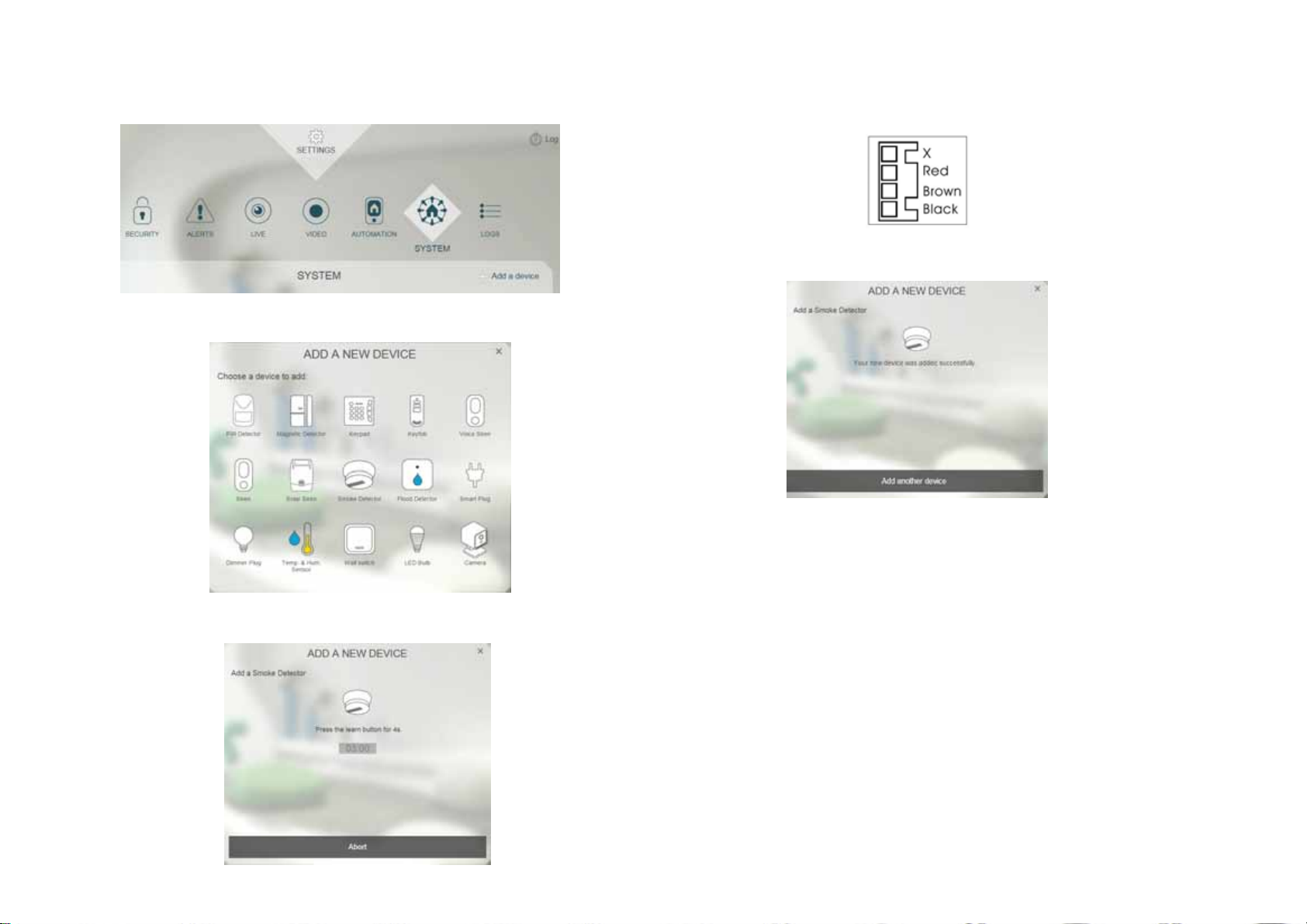
5. Log into the Homesys account from a web browser.
6. Select “System”, then “Add a Device”,
7. Select “Smoke Detector”.
8. The following screen will appear. This mean s the gateway is entering binding
mode.
9. Insert the batteries with correct polarity at this point.
10. Plug the connector back to connector pins of the sensor module. Make
sure its direction is correctly inserted according to the sticker affixed on the
sensor.
11. The screen below will appear in 10 seconds if the process is successful.
12. Time-out will occur if the binding process was unsuccessful. Please refer to
the “Manual Binding” procedure.
Manual Binding
1. Repeat steps 4 to 8 of the Binding with Homesys section.
2. With the battery inserted and connector connected to sensor module,
press and hold the Learning key for 3 seconds then release, and the Link
10
LED ○
mode.
3. Within 5 seconds, the Link LED will stop flashing and then turn off, indicating
will start to flash. This implies SF804-0 has now entered binding
2

the learning procedure is completed. The screen below will appear
indicating the process is successful.
Testing
1. Assemble the transmitter module back to the sensor module.
Note: The smoke LED will flash once every 30 seconds to indicate norma l
operation
2. Press and hold the test button for 3 seconds, the sensor LED will flash and
the horn will emit a loud sound.
3. If the test is successful the system will trigger an alarm and the smoke
detector will sound (alarms are listed in “Events”).
Note: It is necessary that the Homesys gateway is powered and connected
to internet.
4. If the test is unsuccessful, please check the troubleshooting.
Mounting the SF804-0
The detector is designed for use in a single family home or apartment. For
complete coverage, it should be installed in all rooms, halls, storage areas,
basements and attics in each family living unit. Minimum coverage is one
detector on each floor and one in each sleeping area.
1. Remove the mounting bracket ⑪ from the detector by rotating it
counterclockwise.
2. Use a 5mm drill bit to drill two holes and insert the provided plastic wall plugs.
3. Use the two screws and provided plastic wall plugs to attach the bracket to the
wall.
4. Line up the slot of the bracket and the d etector. Push the detector onto the
mounting bracket and turn it clockwise to fix it into place. Pull outward on the
detector to make sure it is securely attached to the mounting bracket.
Tamper Protection
Tamper switch is set inside the housing of SF804-0 to prevent it from being
forcibly removed.
Maintenance
1. One 9V alkaline battery is supplied in the SF804-0. Replace the battery
once a year. When battery level drops, the detector will beep once every
30 seconds and emit radio signals to the gateway. When this occurs, the
battery should be replaced immediately.
2. Clean and vacuum the dust off the detector’s sensing chamber with a soft
cloth when changing the battery.
3

Troubleshooting
The troubleshooting table lists some possible causes and solutions. Please
contact your original retailer or nearest service center if the below solutions
cannot solve your problem.
Symptom Possible Cause Recommendation
SF804-0 LED indicator
not illuminating
No alerts from the
smoke sensor appear
on Homesys interface
1. No battery is
inserted or battery is
flat gateway.
2. The smoke detector
may be out of order.
1. Binding process
failed.
2. The smoke detector
cannot communicate
with the gateway
HSC04.
1. Check if the battery is inserted
properly or replace battery
2. Send the device in for repair
and do not open it
1. Follow the steps for “Manual
Binding”.
2. Place the smoke detector closer
to the gateway.
Reset to factory default:
To reset SF804-0 back to factory default state:
1. Insert the batteries into the unit
2. Press and hold the Learning key for more than 3 seconds and release. The
red LED starts to blink.
3. Within 30 seconds, press and hold the button for more than 6 seconds. The
LED will start to flash, implying the device is reset back to factory mode
Specifications
Battery Type 9V /540mA alkaline battery x 1
Operating Frequency 868MHz (EU) / 923MHz (America)
Range Up to 200 meter line of sight
Battery Life (alkaline) About 1 year @stand-by mode
** Specifications are subject to change and improvement without notice.
WARNING:
Do not dispose of electrical appliances as unsorted municipal waste, use
separate collection facilities instead. Please contact your local government for
information regarding the collection systems available.
If electrical appliances are disposed of in landfills or dumps, hazardous
substances can leak into the groundwater and get into the food chain, dama gin g
your health and well-being.
When replacing old appliances with new once, the retailer is legally obligated to
take back your old appliance for disposal at least for free of charge.
Federal Communication Commission Interference Statement
This equipment has been tested and found to comply with the limits for a Class B
digital device, pursuant to Part 15 of the FCC Rules. These limits are designed
to provide reasonable protection against harmful interference in a residential
installation. This equipment generates, u se s and can
radiate radio frequency energy and, if not installed and used in accordance with
the instructions, may cause harmful interference to radio communications.
However, there is no guarantee that interference will not occur in a particular
installation. If this equipment does cause harmful interference to radio or
television reception, which can be determined by turning the equipment off and
on, the user is encouraged to try to correct the interference by one of the
following measures:
- Reorient or relocate the receiving antenna.
- Increase the separation between the equipment and receiver.
- Connect the equipment into an outlet on a circuit different from that to which the
receiver is connected.
- Consult the dealer or an experienced radio/TV technician for help.
This device complies with Part 15 of the FCC Rules. Operation is subject to the
following two conditions: (1) This device may not cause harmful interference,
and (2) this device must accept any interference received, including interference
that may cause undesired operation.
4

FCC Caution: Any changes or m odifications not exp ressly a pprove d by the p arty
responsible for compliance could void the user's authority to operate this
equipment.
FCC RF Radiation Exposure Statement:
1. This Transmitter must not be co-located or operating in conjunction with any
other antenna or transmitter.
2. This equipment complies with FCC RF radiation exposure limits set forth for
an uncontrolled environment. This equipment should be installed and
operated with a minimum distance of 20 centimeters between the radiator
and your body.
www.everspring.com
3F., No. 50, Sec 1, Zhonghua Rd., Tucheng Dist.,
New Taipei City 23666, R.O.C
5
 Loading...