

Page 1
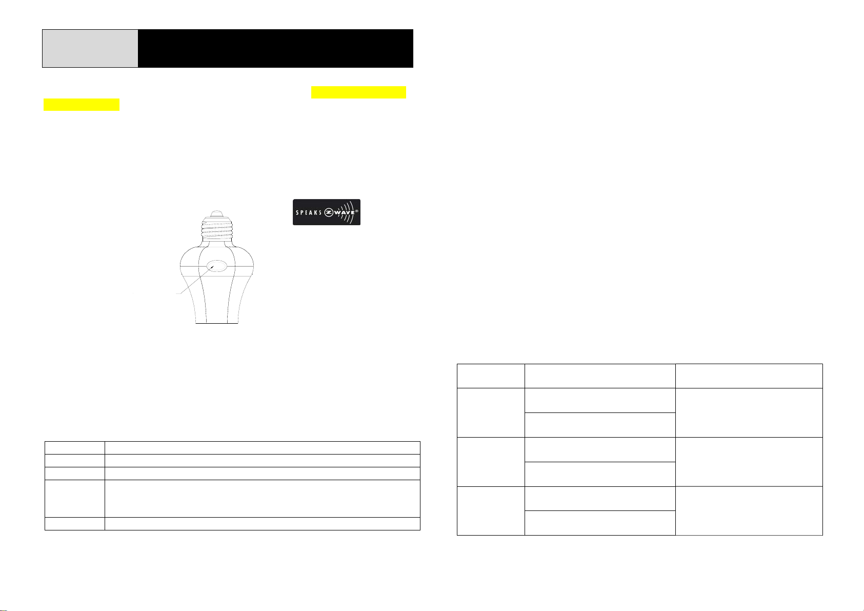
AD145-1
A
r
r
SCREW-IN ON/OFF MODULE
The AD145-1 Screw-in On/Off Module is a lamp holder (for Philips dimmable
LED bulbs only) and a transceiver which is a Z-WaveTM enabled device.
Z-Wave
TM
enabled devices displaying the Z-WaveTM logo can also be used with
this unit regardless of the manufacturer. Inclusion of this Module on other
manufacturer’s Wireless Controller allows remote control of On/Off status.
Each Module is designed to act as a repeater. Repeaters will re-transmit the
RF signal to ensure that the signal is received by its intended destination by
routing the signal around obstacles and radio dead spots.
E26/E27 lamp cap
E26 Lamp Cap
ON/OFF KNOB
LED INDICATOR
Adding to Z-WaveTM Network
In the front casing, there is an On/Off knob coupled with LED indicator. The
knob is used as a Learn Key to carry out inclusion, exclusion or association.
When power is first applied, the LED flashes on and off alternately and
repeatedly at 2-second intervals. It implies that the unit has not been assigned
a node ID and cannot work with Z-Wave enabled devices. Please get familiar
with the terms below before starting the operations.
Function Description
Inclusion Add a Z-Wave enabled device (e.g. Lamp Holder) to Z-Wave network.
Exclusion Delete a Z-Wave enabled device (e.g. Lamp Holder) from the network.
Association After inclusion, you have to define the relationship between devices.
Through association, device can be assigned as master/slave, and specif y
which slave is going to be controlled by which master.
Reset Restore the device to factory default settings.
The table below lists an operation summary of basic Z-Wave functions. Please
refer to the instructions for your Z-Wave
TM
Certificated Primary Controller to
access the setup function, and to include/exclude/associate devices. The lamp
holder executes the function of auto inclusion when…
Auto Inclusion
1. The power is applied for the first time and no ID code has been stored in
the unit.
2. The execution of Exclusion or Reset is successful and the stored ID code is
cleared.
Note: The duration for Auto Inclusion is 4 minutes during which period the node
information of explorer frame will be emitted once every 5 seconds. Unlike the
“Inclusion” procedure described in the next section, the execution of Auto
Inclusion is automatic without the necessity of pressing the learn key.
Module Status and LED Indication
As soon as the light bulb is screwed into the lamp holder, the LED on the Module
will be flashing slowly. This implies that the Module is not yet included in a
Z-Wave system and cannot be controlled by the Wireless Controller. However,
pressing the On/Off knob will control directly the On/Off status of the connected
bulb without using the Wireless Controller .
The following table lists the module status and LED indications:
ction or
Status
Inclusion
Exclusion
Association
Description LED Indication
1. First set the Controlle
Inclusion mode.
2. Press the Learn Key on the
unit once.
1. First set the Controllerinto
Exclusion mode.
2. Press the Learn Key on the
unit once.
1. First set the Controlle
Association mode.
2. Press the Learn Key on the
unit once.
into
into
Press once and LED flashes once.
LED will flash 3 times when code
is emitted successfully.
Press once and LED flashes once.
LED will flash 3 times when code
is emitted successfully.
Press once and LED flashes once.
LED will flash 3 times when code
is emitted successfully.
1
Page 2
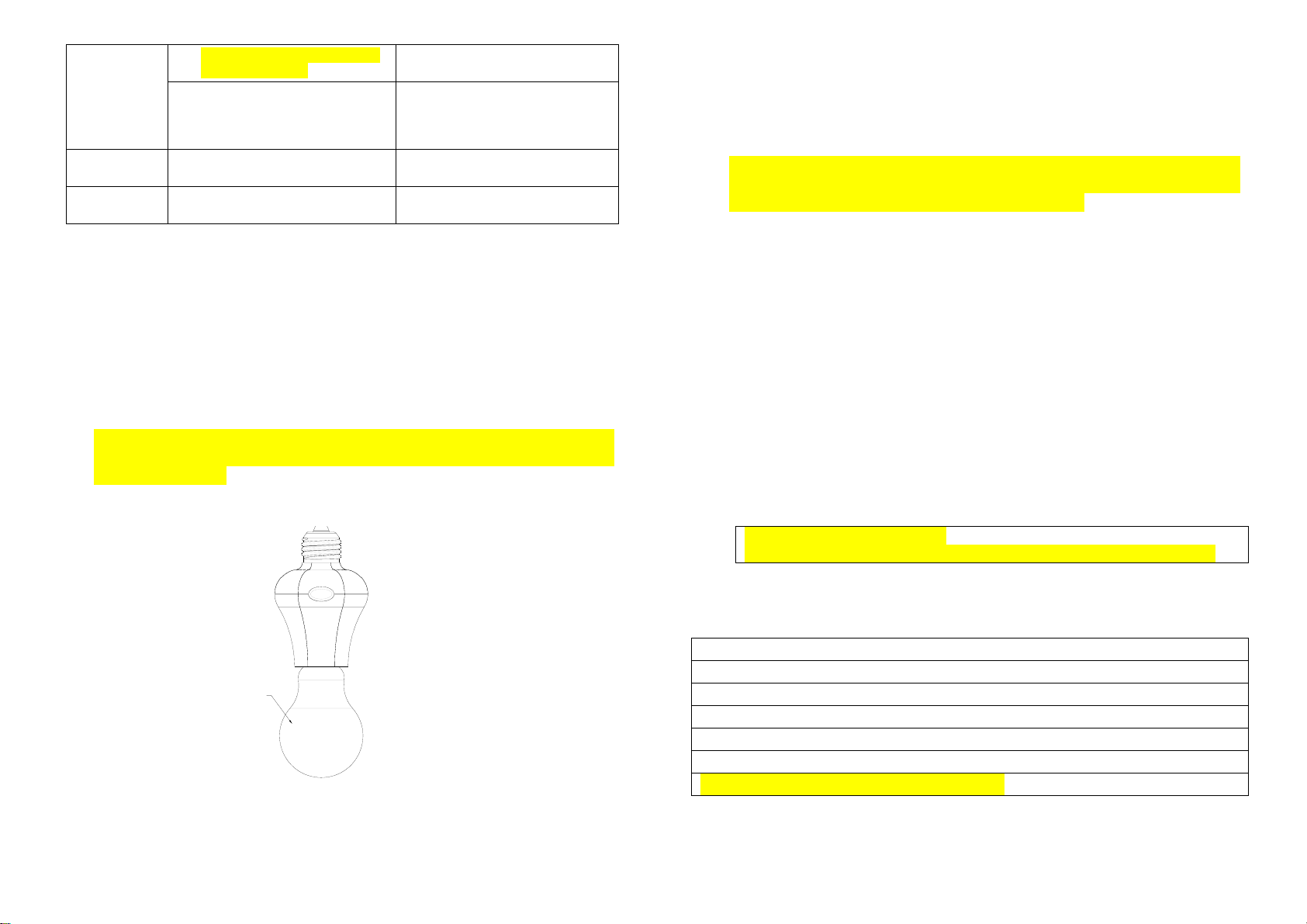
1. Press the Learn Key 5 times
within 5 seconds.
Reset
Empty No ID code memorized.
Normal Normal operation mode.
2. The Home ID and Node ID in
the memory will be cleared
and system will be restored to
factory default.
LED flashes 3 times.
On for 2 seconds & off for 2
seconds.
LED turns on/off according to the
Module being on or off.
Installation
1. Turn off the wall switch on the wall or mains power supply.
2. The lamp cap is E26. Choose the light bulb that fits the standard.
3. The Module is designed for ceiling mounting. Fit the Module into an
existing lamp cap.
4. Place the light bulb into the lamp holder.
Note:
1) The Module cannot be screwed in an air tight environment/ lamp stand.
2) The Module is suitable for use with Philips dimmable LED bulbs only. DO
NOT connect non-lighting appliances to the Module or the connected load
might be damaged.
LIGHT BULB
E26/E27 lamp cap
E26 Lamp Cap
Operation
To turn on or off the bulb controlled by the Module:
z Simply press and release the On/Off knob. The red indicator LED will turn
On/Off and the bulb screwed into the Module will also turn On/Off.
z Dim function: Press and hold down the On/Off knob, after 2 seconds the
brightness of the bulb will start to cycle. Release the knob when the
brightness is right and the bulb will keep the setting.
z With Z-Wave controller: simply press On or Off button on the controller.
z With Z-Wave routing slave: Complete association between routing slave
and the Module through Z-Wave controller, and the routing slave can
control the On/Off status of Module.
Programming
1. Z-Wave’s Groups (Association Command Class Version 2)
1-1. Group supported: The Module support s Group 1 (max. 5 nodes)
1-1-1. Power On
Whenever power is applied, it will send ALARM_REPOR T comm and to the
nodes of Grouping 1 to inform associated devices that the Module is
powered up.
ALARM_REPORT Command
[Command Class Alarm, Alarm Type = 0x02, Alar m Level = 0x01]
Supported Command Class
1. COMMAND_CLASS_BASIC
2. COMMAND_CLASS_SWITCH_MULTILEVEL
3. COMMAND_CLASS_SWITCH_ALL
4. COMMAND_CLASS_MANUFACTURER_SPECIFIC
5. COMMAND_CLASS_VERSION
6. COMMAND_CLASS_ALARM
7. COMMAND_CLASS_ASSOCIATION_V2
2
Page 3
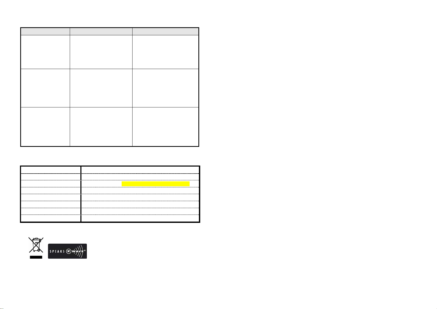
Troubleshooting
Symptom Cause of Failure Recommendation
The module not
working and LED off
The module’s LED
working, but the
connected light bulb
not working
The receiver’s on/off
knob can control
on/off status, but the
transmitter cannot
control the receiver
1. Poor connection
between lamp cap of
mounted ceiling and
lamp cap of the lamp
holder
2. The module broke down
1. Light bulb has burnt out
2. Poor connection or
improper assembly
between lamp cap of
the light bulb and lamp
holder of the module
3. The module broke down
1. Incorrect ID code
2. Transmitter’s battery runs
low
3. Out of receiving range or
poor reception
4. Radio signal is being
jammed or interfered
1. Check if the lamp cap of
mounted ceiling fits well
into the module, and that
voltage is suitable
2. Don’t open up the module
and send it for repair
1. Replace a new bulb
2. The light bulb has screwed
tightly to the lamp holder
of the module
3. Don’t open up the module
and send it for repair
1. Proceed with learning the
ID code
2. Replace the battery of the
Transmitter
3. Get closer to the receiver
4. Wait for a while and try the
operation again
Specification
Operating Voltage 120V AC/60Hz
Type of Lamp Cap E26
Lighting Load Max. 20 Watts (Philips dimmable LED bulbs only)
Operating Temperature 0°C-40°C
Operating Humidity Range 85%RH
Receiving Range 30 meters min. line of sight (indoor)
Frequency Range 908.42MHz
FCC ID FU5AD145
* Specifications are subject to change without notice.
A501112143R 2013/09
Federal Communication Commission Interference Statement
This equipment has been tested and found to comply with the limits for a Class B digital
device, pursuant to Part 15 of the FCC Rules. These limits are designed to provide
reasonable protection against harmful interference in a residential installation. This
equipment generates, uses and can radiate radio frequency energy and, if not installed
and used in accordance with the instructions, may cause harmful interference to radio
communications. However, there is no guarantee that interference will not occur in a
particular installation. If this equipment does cause harmful interference to radio or
television reception, which can be determined by turning the equipment off and on, the
user is encouraged to try to correct the interference by one of the following measures:
- Reorient or relocate the receiving antenna.
- Increase the separation between the equipment and receiver.
- Connect the equipment into an outlet on a circuit different from that to which the
receiver is connected.
- Consult the dealer or an experienced radio/TV technician for help.
This device complies with Part 15 of the FCC Rules. Operati on is s ubject to the foll o wing
two conditions: (1) This device may not cause harmful interference, and (2) this devic e
must accept any interference received, including interference that may cause undesired
operation.
FCC Caution: Any changes or modifications not expressly approved by the party
responsible for compliance could void the user's authority to operate this equipment.
IMPORTANT NOTE:
FCC Radiation Exposure Statement:
This equipment complies with FCC radiation exposure limits set forth for an uncontrolled
environment. End users must follow the specific operating instructions for satisfying RF
exposure compliance.
This transmitter must not be co-located or operating in conjunction with any other
antenna or transmitter.
WARNING:
Do not dispose of electrical appliances as unsorted municipal waste, use
separate collection facilities.
Contact your local government for information regarding the collection systems
available.
If electrical appliances are disposed of in landfills or dumps, hazardous
substances can leak into the groundwater and get into the food chain, damaging
your health and well-being.
When replacing old appliances with new ones, the retailer is legally obligated to
take back your old appliance for disposal at least for free of charge.
3
 Loading...