

HSP02 MOTION DETECTOR
/
y
The Motion Detector is a Z-Wave
any Z-Wave
Z-Wave
TM
TM
enabled network. Z -WaveTM enabled devices displaying the
logo can also be used with the unit regardless of brand. Inclusion of this
Motion Detector in a Wireless Controller system allows remote control of connected
modules when the detector is triggered.
The Motion Detector is designed with two sensors - Passive Infra-Red (PIR) sensor
and light sensor - in order to fulfill the purpose of secu rity and home automation.
When the detector is working with security appliances, it is acting as a security
device by detecting changes in infra-red radiation levels. If a person moves within
or across the detection field, a trigger radi o signal will be transmitted to cause full
alarm condition. Alternatively, when the detector is working with home automation
appliances, the detector can detect both changes in infra-red radiation levels and
percentage of lux levels. At night, when a person moves within or across the field
of detection, a trigger radio signal will be transmitted so as to turn on the connected
lightings for better illumination.
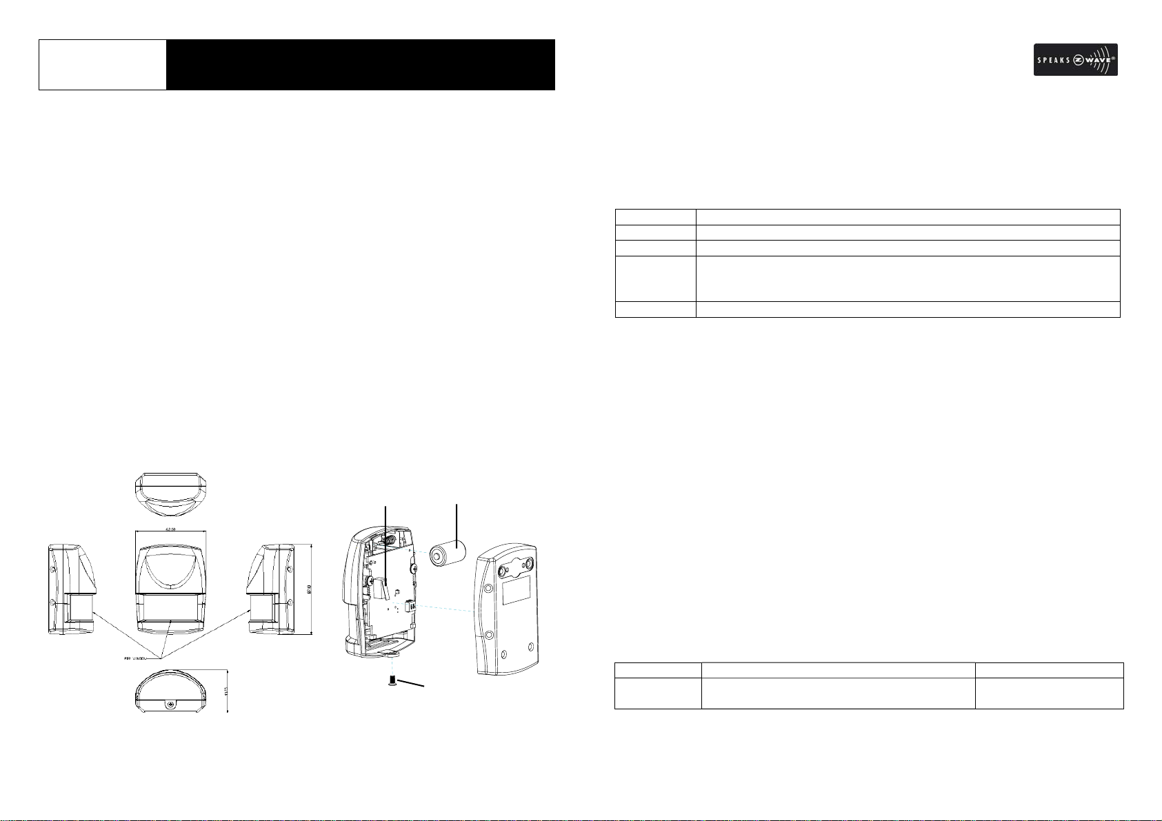
Overview and Battery Installation
The PIR Detector adopts a CR2 3.0V Lithium battery which under normal conditions
will have typical lifespan in excess of 1 year. To install the battery, simply undo the
fixing screw and rem ove the rear co ver, and then place the battery into the
compartment with polarity correctly fitted. Then refit and secure the rear cover.
TM
enabled device which is fully compatible with
Tamper Switch
Link Ke
Battery
Fixing Screw
Include to or Exclude from Z-WaveTM Network
In the rear casin g, there is a link key (t amper switch) which is u sed to carry out
inclusion, exclusion, association or reset. When the detector is first powe red up,
the LED fla shes on and off alternately and repeatedly at 2-seco nd intervals. It
implies that i t has not been assigned a node ID and cannot work with Z-Wave
enabled devices. The detector will stay “awake” for 10 minutes when power is
first applied to allow time for configuration. Please get familiar with the term s
below before starting the operations.
Function Description
Inclusion Add a Z-Wave enabled device (e.g. Motion Detector) to Z-Wave network.
Exclusion Delete a Z-Wave enabled device (e.g. Motion Detector) from the network.
Association After inclusion, you have to define the re lationship between devices.
Trough association, device can be assi gned as master/slave, and spec ify
which slave is going to be controlled by which master.
Reset Restore Detector to factory default.
The table below lists an operation summary of b asic Z-Wave functions. Please
refer to the instructions for your Z-Wave
the setup function, and to include/exclude/associate devices. The detect or
executes the function of auto inclusion when…
Auto Inclusion
The function of auto inclu sion will b e executed as long as the detector does not
have node ID and in situations where…
1. The power is first applied.
2. The execution of exclusio n/reset is successful where the stored node ID is
cleared.
Note: Auto inclu sion timeout is 4 minute durin g which the nod e information of
explorer frame will be emitted once every 5 seconds. Unlike “inclusion” function
as shown in the table below, the execution of auto inclusion is free from pressing
the link key on the detector.
Function Description Indication
No node ID The Z-Wave Controller does not allocate a
node ID to the unit.
TM
Certificated Primary Controller to access
2-second on, 2-second
off
1
Inclusion 1. Have Z-Wave Controller entered inclusion
mode.
2. Pressing link key 3 times within 1.5
seconds will enter inclusion mode.
3. The unit will stay “awake” for 10 minutes.
Exclusion 1. Have Z-Wave Controller entered exclusion
mode.
2. Pressing link key 3 times within 1.5
seconds will enter exclusion mode.
3. The unit will stay “awake” for 10 minutes. 2-second on, 2-second
Reset 1. Press link key 3 times within 1.5 seconds.
2. Within 1 second, press and hold link key
for 5 seconds until LED is OFF.
3. IDs are cleared and all settings will be
reset to factory default.
Association 1. Have Z-Wave Controller entered
association mode.
2. Pressing link key 3 times within 1.5
seconds will enter association operation.
The unit will stay “awake” for 10 minutes.
3. There are two groupings – 1 and 2. Refer
to Z-Wave’s Grouping as described on
page 4.
off (for 2 minutes)
2-second on, 2-second
off (for 2 minutes)
ÚIncluding a node ID allocated by Z-Wave Controller means inclusion. Excluding a node
ID allocated by Z-Wave Controller means exclusion.
ÚFailed or successful results in including/excluding the node ID can be viewed from the
Z-Wave Controller.
ÚWhen “Exclusion” is compl eted, the p arameter 1 of configur ation will be restored t o
default value, while other parameters will retain their settings before exclusion. Press
the tamper switch (link key) once and the green LED will flash for about 25 seconds.
Choosing a Mounting Location
The PIR Detector is suitable for mounting in dry interior locations only.
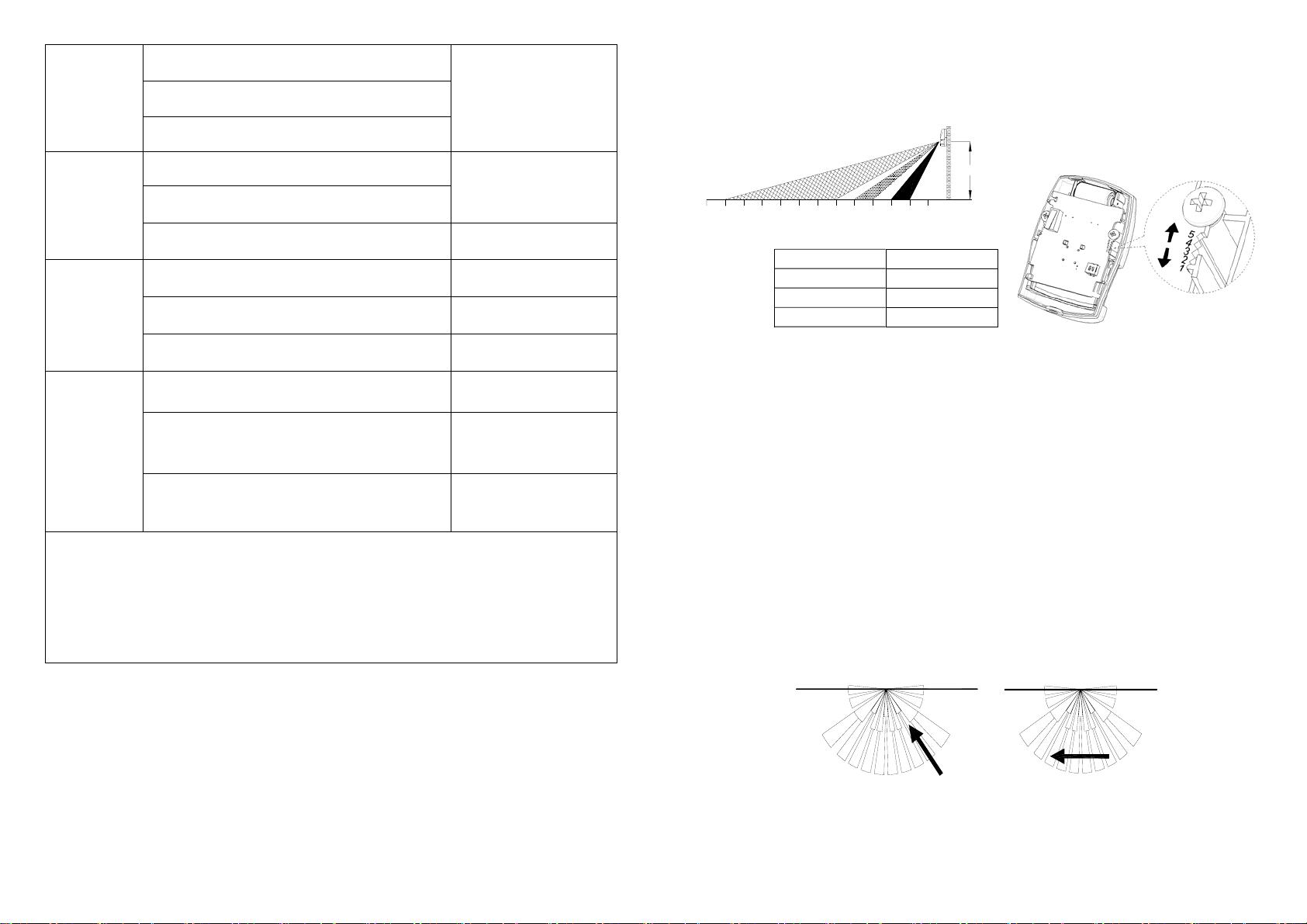
The recommended position for a PIR Detector is in the corner of a room mounted at
a height between 1.8 and 2m. At this height, the detecto r will have a maximum
range of up to 9m with a field of view o f 110°, subject to the position for the P CB
being set in 5. (FIGURE 1& 2) The position of the PCB inside the PIR can be set to
5 different positions to adjust the range of the detector. Setting the PCB in position 3
will reduce the range to 6m approximately, with position 1 providing a range of 3m
approximately. The recommended position setting for the PCB is in position 5.
2M
13
7
89101112
45
6
1
0
23
PCB Position Range
1 3m
3 6m
5 9m
FIGURE 1& 2
When considering and deciding upon the mounting position for the detecto r the
following points should be considered to ensure trouble free operation:
1. Do not locate the detector facing a window or where it is exposed to or facing
direct sunlight. PIR Detectors are not suitable for use in conservatories.
2. Do not locate the detector where it is exposed to ventilators.
3. Do not locate the detector directly above a heat source, (e.g. fire, radiator, boiler,
etc).
4. Where possible, mount the detector in the corner of the room so that the logical
path of an intruder would cut across the fan detection pattern. PIR detectors
respond more effectively to movement across the device than to movement
directly towards it. (FIGURE 3)
Less Sensitive More Sensitive
FIGURE 3
2

5. Do not locate the detector in a position where it is subject to excessive vibration.
6. Ensure that the position selected for the PIR detector is within effective range of
the system, (refer to System Installation and Operating Manual).
Note: When the system is arme d, household pets should not be allowed to go
into an area protected by a PIR detector as their movement would trigger the
PIR and generate a false alarm.
Installation
Ensure that the system is in Test Mode.
1. Undo and re move the fixing scre w from the bottom edge of the detecto r.
Carefully pull the bottom edge of the detecto r away from the rear cove r and
then slide down to release the top clips. (FIGURE 2)
FIGURE 2
2. Carefully drill out the required mounting holes in the rear cover using 3mm drill
according to whether the unit is being mounted in a corner or against a flat wall.
Note: Use 1
nd
group of mounting holes for flat wall installation. (FIGURE 3a & 3b)
2
st
group of mounting holes to fulfill corner mounting installation. Use
FIGURE 3a
Corner mounting
FIGURE 3b
3. Using the rear cover as a template, mark the positions of the fixing holes on the
wall.
4. Fix the rear cover to the wall using the two 18mm No .4 screws and 25mm wall
plugs, (a 5mm hole will be required for the wall plugs). Do not over-tighten the
fixing screws as this may distort or damage the cover.
5. Configure the detector as described below. Rememb er that on initia l
installation that the device needs to be tested.
3
 Loading...