

HSM02 DOOR/WINDOW DETECTOR
The Door/Window Detector is a Z-Wave
with any Z-Wave
Z-Wave
TM
logo can also be used with it regardless of the manufacturer, and ours
TM
enabled network. Z-WaveTM enabled devices displaying the
can also be used in other manufacturer’s Z-Wave
of this Door/Window Detector on other manufacturer’s Wireless Controller menu
allows remote turn-on of connected modules and their connected lighting when the
Detector is triggered.
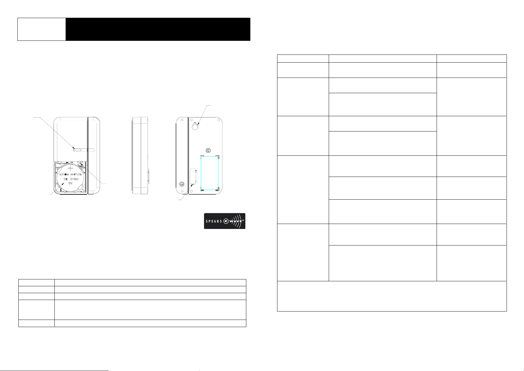
LED
TM
enabled device and is fully compatible
TM
enabled networks. Inclusion
FIXED
SCREW
The table below lists an operation summary of basic Z-Wave functions. Please
refer to the instructions for your Z-Wave
TM
Certificated Primary Controller to access
the setup function, and to include/exclude/associate devices.
Function Description LED Indication
No node ID The Z-Wave Controller does not allocate
a node ID to the unit.
Inclusion 1. Have Z-Wave Controller entered
inclusion mode.
2. Pressing tamper switch three times
within 1.5 second will enter inclusion
mode.
Exclusion 1. Have Z-Wave Controller entered
exclusion mode.
2. Pressing tamper switch three times
within 1.5 second will enter
exclusion mode.
Reset 1. Press tamper switch three times
within 1.5 second.
2-second on, 2-second
off
LED lights up once
whenever tamper switch
is pressed once.
TEMPER
BATTERY
SWITCH
BATTERY
MYLAR
Include to or Exclude from a Z-WaveTM Network
In the front casing, there is a tamper switch which is used to carry out inclusion,
exclusion or reset. When power is first applied, its LED flashes on and off
alternately and repeatedly at 2-second intervals. It implies that it has not been
assigned a node ID and cannot work with Z-Wave enabled devices. Please get
familiar with the terms below before starting the operations.
Function Description
Inclusion Add a Z-Wave enabled device (e.g. Detector) to Z-Wave network.
Exclusion Delete a Z-Wave enabled device (e.g. Detector) from the network.
Association After inclusion, you have to define the relationship between devices.
Trough association, device can be assigned as master/slave, and specify
which slave is going to be controlled by which master.
Reset Restore Detector to factory default.
2. Within 1 second, press and hold the
tamper switch until LED is off.
3. IDs are excluded and all of preset
value will be reset to factory default.
Association 1. Have Z-Wave Controller entered
association mode.
2. When pressing tamper switch three
times within 1.5 second, the unit will
emit the NIF which implies that the
unit has entered association mode.
LED keeps on before
reset function has been
completed.
2-second on, 2-second
off
ÚIncluding a node ID allocated by Z-Wave Controller means inclusion. Excluding a node
ID allocated by Z-Wave Controller means exclusion.
ÚFailed or success in including/excluding the node ID can be v iewed from the Z-Wave
Controller.
1
Choosing A Mounting Location
The Door/Window Detector is suitable for mounting in dry interior locations only.
Decide which doors/windows are to be protected by Door/Window Detectors,
(usually the front and back doors as a minimum will have Door/Window Detectors
fitted). Additional detectors may also be fitted where required to other vulnerable
doors or windows, (e.g. garage, patio/conservatory doors etc).
Note: Take care when fixing the Detect or to a met al frame, or mou nting within 1m of
metalwork (i.e. radiators, water pipes, etc) as this could affect th e radio range of the
device. If required, it may be necessary to space the magnet and detector away
from the metal surface using a plastic or wooden spacer to achieve the necessary
radio range.
Installation
1. Ensure that the system properly powered.
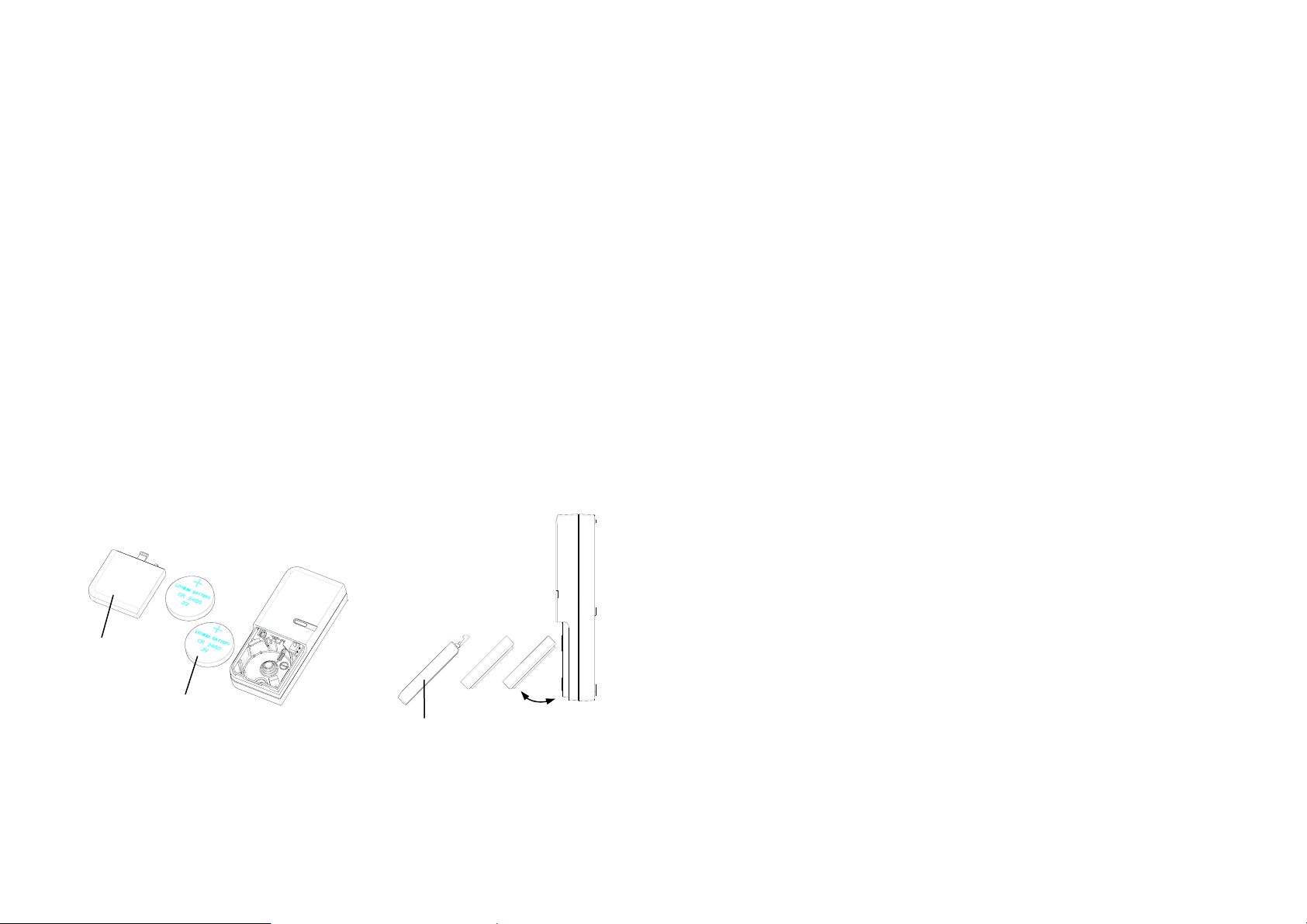
Factory default built in two CR2450 batteries inside the detector and uses a
Mylar film to isolate batteries from electric circuit of the detector. Remove the
battery Mylar film when ready to let the detector work.
If there is no battery inside the detector or need to replace a new battery, please
insert the battery in 45° angle, and then firmly push the battery into the
compartment until the battery clicks into place, as indicated below:
Battery Cover
CR2450
Battery
Battery Cover
45°
2. Using the adhesive tape to fit detector on the door or window.
3. Fit the magnet to the moving part of the door/window opposite the detector
using the adhesive tape.
4. Ensure that the parallel gap between the magnet and detector is less than
20mm and that the matching line on the magnet is pointing towards and aligned
with the line on the detector. An alarm condition will be occurred if the gap is
greater than 35mm.
5. Remove the battery cover with the tamper switch not being pressed on the
detector (test mode), detach or close the magnet from the Detector, the LED on
the detector will illuminate.
6. After proper installation and test, put the battery cover back to the detector and
the detector enters the normal mode.
Note: After removing batteries, wait for 5 seconds to refit batteries.
Operation
1. If first use of HSM02 with no node ID, LED will start twinkling for 30 sec. to lead
the user for Inclusion. After HSM02 finishing Inclusion and enter sleeping
mode, the unit will wake up by pressing Tamper and the user can see the LED
start lighting up shortly every sec., currently the unit can receive set up for
controller. After 30 sec., the unit will enter sleeping mode again, if set up is
still needed, the user can press Tamper once more for HSM02 to be awake for
another 30 sec.
2. Due to limited power from CR2450, the unit may not continuously operate for a
long time due to power consumption. Therefore, set up time for HSM02
should be minimized, and repeatedly press of Tamper should be avoided as
well, in order to prevent unusual incident by a quick battery voltage drop down.
3. User can enter test mode by releasing or not pressing the Tamper SW, in the
meantime if magnetic sensor is triggered then the LED will be illuminated.
User can confirm whether the Tamper SW has been pressed properly by
implementing this function. When Tamper SW is to be pressed and enter
normal mode, LED will not be illuminated even if the magnetic sensor is
triggered, unless low battery is detected.
2
 Loading...