

Installation and Operating Instruction
Product Layout
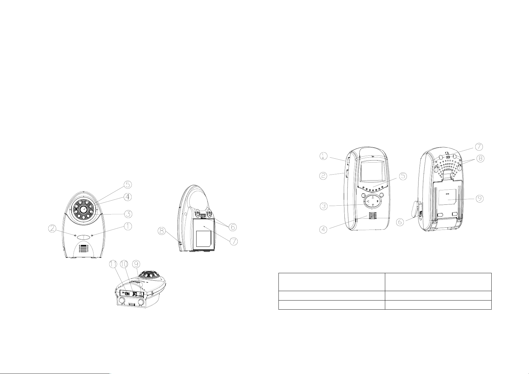
Camera
① Low battery indicator LED
② Power indicator LED
③ Microphone
④ Infrared LEDs
⑤ Lens
⑥ Keyholes
⑦ Battery compartment
⑧ 6V DC power adaptor jack
⑨ Learn button
⑩ Power On/Off switch
⑪ Channel selection switch
(Fig. 1)
Fig. 1
Monitor
① Sensitivity level control
② Volume/power control
③ Brightness/contrast ratio control
④ Speaker
⑤ LEDs indicator
⑥ 6V DC power adaptor jack
⑦ Hang up hole
⑧ Keyholes
⑨ Swiveling pivot
(Fig. 2)
Fig. 2
Kit Content
1 x Camera 4 x 1.5V AA-size Battery (for
Monitor)
1 x Monitor All Fixing Screws
1 x AC/DC Adaptor (for Camera) This manual
1
Introduction
This package is designed to facilitate the users who intend constant
observation of the particular place where continuous caring or surveillance is
needed. Both Camera and Monitor units are suitable for indoor use only.
Either 4 AA-size batteries or an AC/DC adaptor can be used as their power
source. When the battery level falls below an unacceptable level, the “LOW
BATTERY” indicator on the front of the Camera and Monitor will light up. When
this occurs the batteries should be replaced as soon as possible.
Setting Up the Camera
Power Supply
The Camera adopts either 4 AA-size batteries or the AC/DC adaptor (no
supplied).
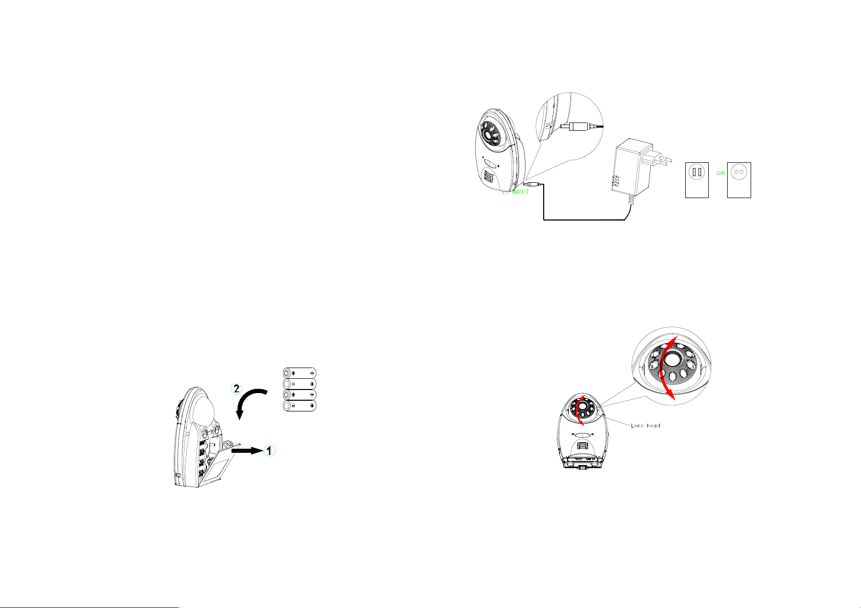
Loading the Batteries
1. Open the battery compartment cover on the rear of the camera.(Fig. 3)
2. Insert 4 AA-size batteries, ensuring that correct polarity is put. (Fig. 3)
3. Refit the battery compartment cover and make sure it is locked securely.
Note: Never mix old batteries with new ones.
Remove the batteries from the Camera if you do not plan to use it for a
long period of time.
Fig. 3
Using the AC/DC adaptor
Plug one end of the power adaptor into a wall outlet and the other end into the
Camera. The specification of AC/DC adaptor is 6V/500mA with regulator. (Fig.
4)
Note: The AC/DC adaptor shall remain readily operable.
O R
D C I N P U T
Fig. 4
Installing the Camera
The Camera is suitable for mounting in dry interior locations only. 3 types of
installation can be made, such as wall mount, table stand or clip-on the crib.
Place the Camera in a convenient location, point the lens towards the
observed area and adjust the angle by adjusting the lens head vertically. (Fig.
5)
Fig. 5
Wall Mounting the Camera
Note: The Monitor reception should be tested before fixing the camera in place.
Ideally you will need someone to hold the Camera against the wall in the
selected mounting area while you check the reception on the Monitor. If
2
interference or other problems occur, refer to the Troubleshooting. You may
need to select a different location in the room for mounting the Camera.
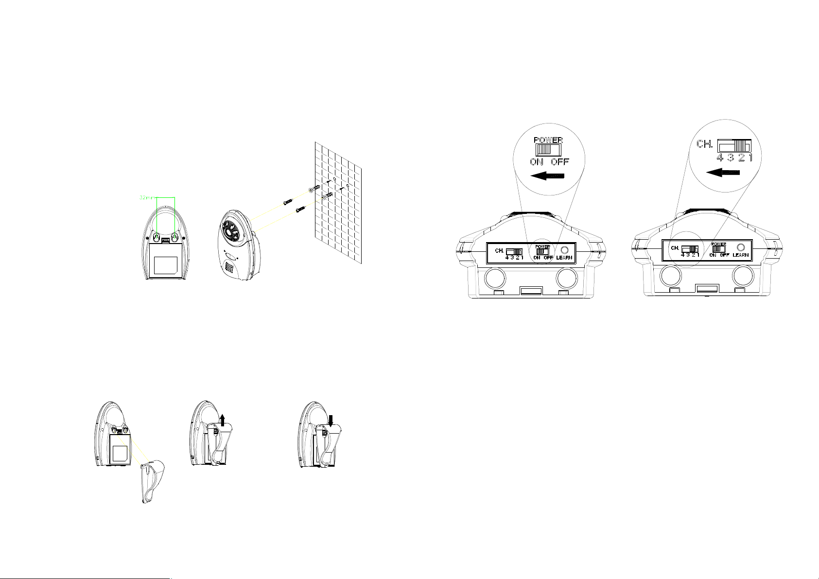
1. Decide on the appropriate mounting location. Drill two holes 32mm apart in
a line and fit wall plugs. (Fig. 6)
2. Insert fixing screws until almost fully home and hang the Camera over
these screws using the two keyhole slots in the rear of the Camera. (Fig. 6)
Fig. 6
Operating the Camera
1. The ON/OFF slide switch is for turning on and off the power. (Fig. 9)
2. Up to four cameras can be connected to the Monitor. Set the channel
switch (numbered 1~4) that matches to that of the Monitor you plan to
observe. (Fig. 9)
Clipping on the Camera
1. Use the clip as supplied for fixing the Camera on the crib or table edge.
(Fig. 7)
2. Place the clip to the two slots on the top of Camera and lift it up to fit it in
place. (Fig. 7)
Note: For removing the clip, push the clip downward. (Fig. 8)
Fig. 7 Fig. 8
3
Note: If more than 2 cameras are in use, do not set the same channel at
the same time.
3. Learning the ID code
In order to prevent any unauthorized attempt to operate or disarm your
system, you must configure your system to accept radio signals only from
your own system devices. All Cameras have their unique ID code, the
Monitor must learn their codes individually for the system to operate
correctly.
Pressing the learn button will emit the ID code to the Monitor, subject to
the Monitor enters ID code learn mode. Refer to page 5 for detailed
instruction.
4. Night Vision Mode (Infrared LEDs)
Fig. 9
 Loading...